EP4564633A1 - Leistungssystem und frequenzmodulationssteuerungsverfahren dafür - Google Patents
Leistungssystem und frequenzmodulationssteuerungsverfahren dafür Download PDFInfo
- Publication number
- EP4564633A1 EP4564633A1 EP23844750.2A EP23844750A EP4564633A1 EP 4564633 A1 EP4564633 A1 EP 4564633A1 EP 23844750 A EP23844750 A EP 23844750A EP 4564633 A1 EP4564633 A1 EP 4564633A1
- Authority
- EP
- European Patent Office
- Prior art keywords
- input current
- frequency
- change value
- power system
- hydrogen generator
- Prior art date
- Legal status (The legal status is an assumption and is not a legal conclusion. Google has not performed a legal analysis and makes no representation as to the accuracy of the status listed.)
- Pending
Links
Images



Classifications
-
- H—ELECTRICITY
- H02—GENERATION; CONVERSION OR DISTRIBUTION OF ELECTRIC POWER
- H02J—ELECTRIC POWER NETWORKS; CIRCUIT ARRANGEMENTS OR SYSTEMS FOR SUPPLYING OR DISTRIBUTING ELECTRIC POWER; SYSTEMS FOR STORING ELECTRIC ENERGY
- H02J3/00—Circuit arrangements for AC mains or AC distribution networks
- H02J3/001—Arrangements for handling faults or abnormalities, e.g. emergencies or contingencies
- H02J3/0014—Arrangements for handling faults or abnormalities, e.g. emergencies or contingencies for preventing or reducing power oscillations in networks
- H02J3/00142—Oscillations concerning frequency
-
- H—ELECTRICITY
- H02—GENERATION; CONVERSION OR DISTRIBUTION OF ELECTRIC POWER
- H02J—ELECTRIC POWER NETWORKS; CIRCUIT ARRANGEMENTS OR SYSTEMS FOR SUPPLYING OR DISTRIBUTING ELECTRIC POWER; SYSTEMS FOR STORING ELECTRIC ENERGY
- H02J15/00—Systems for storing electric energy specially adapted for power networks
- H02J15/50—Systems for storing electric energy specially adapted for power networks using stored hydrogen
-
- H—ELECTRICITY
- H02—GENERATION; CONVERSION OR DISTRIBUTION OF ELECTRIC POWER
- H02J—ELECTRIC POWER NETWORKS; CIRCUIT ARRANGEMENTS OR SYSTEMS FOR SUPPLYING OR DISTRIBUTING ELECTRIC POWER; SYSTEMS FOR STORING ELECTRIC ENERGY
- H02J3/00—Circuit arrangements for AC mains or AC distribution networks
- H02J3/001—Arrangements for handling faults or abnormalities, e.g. emergencies or contingencies
- H02J3/0012—Arrangements for handling faults or abnormalities, e.g. emergencies or contingencies characterised by the contingency detection means in AC networks, e.g. using phasor measurement units [PMU], synchrophasors or contingency analysis
-
- H—ELECTRICITY
- H02—GENERATION; CONVERSION OR DISTRIBUTION OF ELECTRIC POWER
- H02J—ELECTRIC POWER NETWORKS; CIRCUIT ARRANGEMENTS OR SYSTEMS FOR SUPPLYING OR DISTRIBUTING ELECTRIC POWER; SYSTEMS FOR STORING ELECTRIC ENERGY
- H02J3/00—Circuit arrangements for AC mains or AC distribution networks
- H02J3/28—Arrangements for balancing of the load in networks by storage of energy
-
- H—ELECTRICITY
- H02—GENERATION; CONVERSION OR DISTRIBUTION OF ELECTRIC POWER
- H02J—ELECTRIC POWER NETWORKS; CIRCUIT ARRANGEMENTS OR SYSTEMS FOR SUPPLYING OR DISTRIBUTING ELECTRIC POWER; SYSTEMS FOR STORING ELECTRIC ENERGY
- H02J3/00—Circuit arrangements for AC mains or AC distribution networks
- H02J3/38—Arrangements for feeding a single network from two or more generators or sources in parallel; Arrangements for feeding already energised networks from additional generators or sources in parallel
-
- H—ELECTRICITY
- H02—GENERATION; CONVERSION OR DISTRIBUTION OF ELECTRIC POWER
- H02J—ELECTRIC POWER NETWORKS; CIRCUIT ARRANGEMENTS OR SYSTEMS FOR SUPPLYING OR DISTRIBUTING ELECTRIC POWER; SYSTEMS FOR STORING ELECTRIC ENERGY
- H02J2101/00—Supply or distribution of decentralised, dispersed or local electric power generation
- H02J2101/20—Dispersed power generation using renewable energy sources
- H02J2101/22—Solar energy
-
- Y—GENERAL TAGGING OF NEW TECHNOLOGICAL DEVELOPMENTS; GENERAL TAGGING OF CROSS-SECTIONAL TECHNOLOGIES SPANNING OVER SEVERAL SECTIONS OF THE IPC; TECHNICAL SUBJECTS COVERED BY FORMER USPC CROSS-REFERENCE ART COLLECTIONS [XRACs] AND DIGESTS
- Y02—TECHNOLOGIES OR APPLICATIONS FOR MITIGATION OR ADAPTATION AGAINST CLIMATE CHANGE
- Y02E—REDUCTION OF GREENHOUSE GAS [GHG] EMISSIONS, RELATED TO ENERGY GENERATION, TRANSMISSION OR DISTRIBUTION
- Y02E60/00—Enabling technologies; Technologies with a potential or indirect contribution to GHG emissions mitigation
- Y02E60/30—Hydrogen technology
- Y02E60/36—Hydrogen production from non-carbon containing sources, e.g. by water electrolysis
Definitions
- the present disclosure relates to the technical field of frequency regulation of power system, and in particular to a power system and a frequency regulation control method therefor.
- renewable energy power generation can reduce pollution and has a certain positive effect, it will lead to problems such as node frequency fluctuations in the power grid, due to the randomness and fluctuation of renewable energy power generation.
- the input current from the hydrogen generator unit is configured based on the detected system frequency through a relationship between system power consumption and frequency fluctuation, to achieve the frequency regulation control of the power system, which solves the problem of frequency fluctuations in the power system caused by the randomness and fluctuation of renewable energy power generation.
- a frequency regulation control method for a power system including:
- an upper limit of the preset frequency deviation range is f 0 + ⁇ 1
- a lower limit of the preset frequency deviation range is f 0 - ⁇ 2 ; where f 0 represents the rated grid frequency, ⁇ 1 represents a maximum increment, and ⁇ 2 represents a maximum decrement.
- the calculating a change value of an input current from a hydrogen generator unit in the power system, based on the present grid frequency and a rated grid frequency includes:
- the determining a target input current from the hydrogen generator unit, based on a relationship between the change value of the input current from the hydrogen generator unit and a threshold of the change value of the input current and a relationship between a changed input current and a threshold of the changed input current includes:
- the first preset condition is: ⁇ I min ⁇ ⁇ I i ⁇ ⁇ I m a x and I min ⁇ I i + ⁇ I i ⁇ I m a x ;
- the adjusting an input current from the hydrogen generator unit based on the target input current includes:
- the method further includes: returning to the step of determining whether the present grid frequency of the power system is within the preset frequency deviation range.
- the frequency regulation control method for the power system if it is determined that the present grid frequency is within the preset frequency deviation range, returning to the step of determining whether the present grid frequency in the power system is within the preset frequency deviation range, until it is determined that the present grid frequency is not within the preset frequency deviation range.
- a power system in the present disclosure.
- the power system includes: a renewable energy power generation unit, an energy storage unit, and a controller; where the energy storage unit at least includes a hydrogen generator unit; and the controller is communicatively connected to the energy storage unit, to perform the frequency regulation control method for the power system according to any one of embodiments in the first aspect by sampling the present grid frequency in the power system in real time.
- a frequency regulation control method for a power system includes: determining whether a present grid frequency of a power system is within a preset frequency deviation range; calculating a change value of an input current from a hydrogen generator unit in the power system, based on the present grid frequency and a rated grid frequency, in response to determining that the present grid frequency is not within the preset frequency deviation range; determining a target input current from the hydrogen generator unit, based on a relationship between the change value of the input current from the hydrogen generator unit and a threshold of the change value of the input current and a relationship between a changed input current and a threshold of the changed input current; and adjusting an input current from the hydrogen generator unit based on the target input current, to adjust a grid frequency of the power system to the preset frequency deviation range.
- the frequency regulation control of the power system is achieved by configuring input current from the hydrogen generator unit based on the detected system frequency through the relationship between system power consumption and frequency fluctuation.
- the hydrogen generator unit greatly plays the role of frequency regulation for the power system in the production hydrogen process, which solves the problem of frequency fluctuations in the power system caused by the randomness and fluctuation of renewable energy power generation.
- a frequency regulation control method for a power system is provided in the present disclosure.
- the frequency regulation control of the power system is achieved by configuring input current from the hydrogen generator unit based on the detected system frequency through the relationship between system power consumption and frequency fluctuation.
- the hydrogen generator unit greatly plays the role of frequency regulation for the power system in the production process, which solves the problem of frequency fluctuations in the power system caused by the randomness and fluctuation of renewable energy power generation.
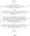
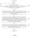
- a frequency regulation control method for a power system includes following steps S100 to S106.
- step S100 it is determined whether a present grid frequency of the power system is within a preset frequency deviation range.
- the present grid frequency of the power system can be obtained by monitoring the grid frequency of the power system.
- the preset frequency deviation range is generally a frequency deviation range at the grid side.
- the upper limit of the preset frequency deviation range may be f 0 + ⁇ 1
- the lower limit of the preset frequency deviation range may be f 0 - ⁇ 2 .
- f 0 represents the rated grid frequency
- ⁇ 1 represents a maximum increment
- ⁇ 2 represents a maximum decrement.
- the maximum increment ⁇ 1 and the maximum decrement ⁇ 2 may be preset, may be determined based on the specific application environment and user requirement or based on the installed capacity of the power grid.
- the values of ⁇ 1 and ⁇ 2 may be equal or different, which are not specifically limited in the present disclosure, and all fall within the protection scope of the present disclosure.
- step S102 If it is determined that the present grid frequency is within the preset frequency deviation range, it means that the present grid frequency of the power system is within a reasonable range and no frequency regulation is required. If it is determined that the present grid frequency is not within the preset frequency deviation range, it means that the present grid frequency of the power system is not within the reasonable range, and step S102 needs to be performed.
- step S102 a change value of an input current from a hydrogen generator unit in the power system is calculated based on the present grid frequency and a rated grid frequency.
- the rated grid frequency is the rated frequency of the power grid in the power system, which is generally 50Hz or 60Hz.
- the step S102 of calculating a change value of an input current from a hydrogen generator unit in the power system based on the present grid frequency and a rated grid frequency mainly includes the following steps S200 and S202, as shown in FIG. 2 .
- step S200 a grid frequency difference between the present grid frequency and the rated grid frequency is determined.
- ⁇ f i the grid frequency difference
- f i the present grid frequency
- f 0 the rated grid frequency.
- the grid frequency difference between the present grid frequency and the rated grid frequency can also be determined through other existing methods, which are not specifically limited in the present disclosure and all fall within the protection scope of the present disclosure.
- step S202 the change value of the input current from the hydrogen generator unit is calculated based on the grid frequency difference and a current adjustment proportion function.
- the grid frequency difference can be substituted into the current adjustment proportion function to calculate the change value of the input current from the hydrogen generator unit.
- an optimal proportional gain K p can be obtained through offline trials.
- the optimal proportional gain K p can be determined through other existing methods or based on the specific application environment and user requirement, which are not specifically limited in the present disclosure and all fall within the protection scope of the present disclosure.
- step S104 a target input current from the hydrogen generator unit is determined, based on a relationship between the change value of the input current from the hydrogen generator unit and a threshold of the change value of the input current and a relationship between a changed input current and a threshold of the changed input current.
- the target input current is determined as a sum of a present input current and the change value of the input current, in a case that the relationship between the change value of the input current from the hydrogen generator unit and the threshold of the change value of the input current and the relationship between the changed input current and the threshold of the changed input current meet a first preset condition.
- the target input current is determined as a sum of the present input current and an upper limit of the change value of the input current, in a case that the relationship between the change value of the input current from the hydrogen generator unit and the threshold of the change value of the input current and the relationship between the changed input current and the threshold of the changed input current meet a second preset condition.
- the target input current is determined as a sum of the present input current and a lower limit of the change value of the input current, in a case that the relationship between the change value of the input current from the hydrogen generator unit and the threshold of the change value of the input current and the relationship between the changed input current and the threshold of the changed input current meet a third preset condition.
- the target input current is determined as an upper limit of the changed input current, in a case that the relationship between the change value of the input current from the hydrogen generator unit and the threshold of the change value of the input current and the relationship between the changed input current and the threshold of the changed input current meet a fourth preset condition.
- the target input current is determined as a lower limit of the changed input current, in a case that the relationship between the change value of the input current from the hydrogen generator unit and the threshold of the change value of the input current and the relationship between the changed input current and the threshold of the changed input current meet a fifth preset condition.
- the first preset condition may be: ⁇ I min ⁇ ⁇ I i ⁇ ⁇ I m ax and I min ⁇ I i + ⁇ I i ⁇ I m ax ;
- the second preset condition may be: ⁇ I i > ⁇ I m ax and I mln ⁇ I i + ⁇ I i ⁇ I m ax ;
- the third preset condition may be: ⁇ I i ⁇ ⁇ I min and I min ⁇ I i + ⁇ I i ⁇ I max ;
- the fourth preset condition may be: I i + ⁇ I i > I m a x ;
- the fifth preset condition may be: I i + ⁇ I i ⁇ I min .
- ⁇ I i represents the change value of the input current
- ⁇ I min represents the lower limit of the change value of the input current
- ⁇ I max represents the upper limit of the change value of the input current
- I i + ⁇ I i represents the changed input current
- I min represents the lower limit of the changed input current
- I m a x represents the upper limit of the changed input current
- I i represents the present input current.
- the target input current from the hydrogen generator unit is I i +1 .
- step S106 an input current from the hydrogen generator unit is adjusted based on the target input current to adjust a grid frequency of the power system to the preset frequency deviation range.
- the step S106 of adjusting an input current from the hydrogen generator unit based on the target input current includes the following steps S300 to S304.
- step S300 the present input current from the hydrogen generator unit is compared with the target input current.
- step S302 If the present input current from the hydrogen generator unit is less than the target input current, step S302 is performed; and if the present input current from the hydrogen generator unit is greater than the target input current, step S304 is performed.
- step S302 direct-current power consumption of an electrolyzer in the hydrogen generator unit is increased until the input current from the hydrogen generator unit is equal to the target input current.
- the direct-current power consumption of the electrolyzer in the hydrogen generator unit may be increased until the input current from the hydrogen generator unit is equal to the target input current, in the case that the present input current through the hydrogen generator unit is less than the target input current. In this way, the grid frequency of the power system is reduced such that the grid frequency of the power system falls within the preset frequency deviation range.
- the direct-current power consumption of the electrolyzer in the hydrogen generator unit can be increased by increasing the voltage, power and hydrogen yield of the electrolyzer in the hydrogen generator unit.
- other existing methods can also be used to increase the direct-current power consumption of the electrolyzer in the hydrogen generator unit, which are not limited in the present disclosure and all fall within the protection scope of the present disclosure.
- step S304 direct-current power consumption of the electrolyzer in the hydrogen generator unit is decreased until the input current from the hydrogen generator unit is equal to the target input current.
- the direct-current power consumption of the electrolyzer in the hydrogen generator unit may be decreased until the input current from the hydrogen generator unit is equal to the target input current, in the case that the present input current from the hydrogen generator unit is greater than the target input current. In this way, the grid frequency of the power system is increased, such that the grid frequency of the power system falls within the preset frequency deviation range.
- the direct-current power consumption of the electrolyzer in the hydrogen generator unit can be decreased by decreasing the voltage, power and hydrogen production of the electrolyzer in the hydrogen generator unit.
- other existing methods can also be used to decrease the direct-current power consumption of the electrolyzer in the hydrogen generator unit, which are not limited in the present disclosure and all fall within the protection scope of the present disclosure.
- the present grid frequency of the power system may an average grid frequency at a certain period, which is determined based on the specific application environment and user requirement and all fall within the protection scope of the present disclosure.
- the input current from the hydrogen generator unit can be continuously adjusted based on the monitored frequency value outside the preset frequency deviation range to change the direct-current power consumption of the hydrogen generator unit, thereby achieving frequency regulation control of the power system.
- a frequency regulation control method for a power system includes: determining whether a present grid frequency of a power system is within a preset frequency deviation range; calculating a change value of an input current from a hydrogen generator unit of the power system, based on the present grid frequency and a rated grid frequency, in response to determining that the present grid frequency is not within the preset frequency deviation range; determining a target input current from the hydrogen generator unit, based on a relationship between the change value of the input current from the hydrogen generator unit and a threshold of the change value of the input current and a relationship between a changed input current and a threshold of the changed input current; and adjusting an input current from the hydrogen generator unit based on the target input current, to adjust a grid frequency of the power system to the preset frequency deviation range.
- the frequency regulation control of the power system is achieved by configuring input current from the hydrogen generator unit based on the detected system frequency through the relationship between system power consumption and frequency fluctuation.
- the hydrogen generator unit greatly plays the role of frequency regulation for the power system in the production hydrogen process, which solves the problem of frequency fluctuation in the power system caused by the randomness and fluctuation of renewable energy power generation, and fills the research gap in the field of frequency regulation in the power system with the assistance of hydrogen production by electrolyzing water.
- the frequency regulation control method for the power system further includes: returning to the step of determining whether the present grid frequency of the power system is within the preset frequency deviation range. That is, the method returns to perform step S100.
- the method after adjusting the input current from the hydrogen generator unit based on the target input current, the method returns to perform step S100 to ensure that the adjusted grid frequency of the power system accurately falls within the preset frequency deviation range. It can be determined that whether the present grid frequency of the power system falls within the preset frequency deviation range. If the present grid frequency of the power system is not within the preset frequency deviation range after adjusting the input current from the hydrogen generator unit based on the target input current, the adjustment is performed again based on the adjusted grid frequency to further ensure that the adjusted grid frequency falls within the preset frequency deviation range.
- a frequency regulation period can be set.
- the above frequency regulation control method for the power system is executed in the set frequency regulation period.
- the frequency regulation period may be determined based on the specific application environment and user requirement, which are not limited in the present disclosure and all fall within the protection scope of the present disclosure.
- the frequency regulation control method for the power system further includes: in response to determining that the present grid frequency of the power system is within the preset frequency deviation range, returning to the step of determining whether the present grid frequency of the power system is within the preset frequency deviation range. That is, step S100 is returned to be performed.
- the subsequent steps of the frequency regulation control method for the power system can be executed when it is determined that the present grid frequency is not within the preset frequency deviation range, thereby realizing frequency regulation of the power system.
- the frequency regulation control method for the power system may include the following steps S1 to S6.
- step S1 an actual frequency f i of the power grid at time i is monitored, for a network containing the process of hydrogen production by electrolyzing water.
- Whether the actual frequency f i of the power grid in the i-th period is within the allowable frequency range is determined by the mathematical expression f 0 - ⁇ 2 ⁇ f i ⁇ f 0 + ⁇ 1 , where f 0 is the rated frequency, ⁇ 1 is a maximum increment, and ⁇ 2 is a maximum decrement.
- step S3 a difference between the actual frequency and a rated frequency in the i-th period is calculated.
- step S4 the change value ⁇ I i of the input current by the process for producing hydrogen by electrolyzing water in the i-th period is calculated based on the proportional process.
- K p is a proportional gain.
- the optimal solution of the proportional gain can be obtained based on offline trials.
- step S5 a new input current I i +1 by process for producing hydrogen by electrolyzing water in an i+1-th period is set, based on the relationship between the change value ⁇ I i and a threshold ⁇ I max and ⁇ I min of the change value of the input current, and the relationship between the changed value I i + ⁇ I i and the threshold I max and I min of the changed value.
- the actual frequency of the power grid in the above example is equivalent to the present grid frequency of the power system in the above embodiment.
- the frequency allowable range is equivalent to the preset frequency deviation range in the above embodiment.
- the rated frequency is equivalent to the rated grid frequency in the above embodiment.
- the proportional process is equivalent to the current adjustment proportion function.
- the change value of the input current by the process for producing hydrogen by electrolyzing water is equivalent to the change value of the input current from the hydrogen generator unit in the above embodiment.
- the changed value is equivalent to changed input current in the above embodiment.
- a power system is further provided in an embodiment of the present disclosure.
- the power system includes: a renewable energy power generation unit, an energy storage unit and a controller; where the energy storage unit at least includes a hydrogen generator unit.
- the controller is communicatively connected to the energy storage unit, to perform the frequency regulation control method for the power system according to any one of the above embodiments by sampling the present grid frequency in the power system in real time.
- the energy storage unit may further include other existing energy storage equipment, which may be determined based on the specific application environment and user requirement and fall within the protection scope of the present disclosure.
- the controller may be an upper computer in the power system, or may be other equipment with control functions.
- the specific type of the controller is not limited in the present disclosure, and all types of controllers fall within the protection scope of the present disclosure.
Landscapes
- Engineering & Computer Science (AREA)
- Power Engineering (AREA)
- Control Of Eletrric Generators (AREA)
- Electrolytic Production Of Non-Metals, Compounds, Apparatuses Therefor (AREA)
Applications Claiming Priority (2)
| Application Number | Priority Date | Filing Date | Title |
|---|---|---|---|
| CN202210877108.3A CN115224703A (zh) | 2022-07-25 | 2022-07-25 | 电力系统及其调频控制方法 |
| PCT/CN2023/070601 WO2024021531A1 (zh) | 2022-07-25 | 2023-01-05 | 电力系统及其调频控制方法 |
Publications (1)
| Publication Number | Publication Date |
|---|---|
| EP4564633A1 true EP4564633A1 (de) | 2025-06-04 |
Family
ID=83614750
Family Applications (1)
| Application Number | Title | Priority Date | Filing Date |
|---|---|---|---|
| EP23844750.2A Pending EP4564633A1 (de) | 2022-07-25 | 2023-01-05 | Leistungssystem und frequenzmodulationssteuerungsverfahren dafür |
Country Status (4)
| Country | Link |
|---|---|
| US (1) | US20250337244A1 (de) |
| EP (1) | EP4564633A1 (de) |
| CN (1) | CN115224703A (de) |
| WO (1) | WO2024021531A1 (de) |
Families Citing this family (3)
| Publication number | Priority date | Publication date | Assignee | Title |
|---|---|---|---|---|
| CN115224703A (zh) * | 2022-07-25 | 2022-10-21 | 阳光电源(南京)有限公司 | 电力系统及其调频控制方法 |
| JP2025031393A (ja) * | 2023-08-25 | 2025-03-07 | 株式会社日立製作所 | 水電解槽システムおよび水電解槽システムの制御方法 |
| CN119246947B (zh) * | 2024-12-03 | 2025-03-14 | 国能日新科技股份有限公司 | 基于自相关频率拟合的新能源一次调频采集方法和装置 |
Family Cites Families (8)
| Publication number | Priority date | Publication date | Assignee | Title |
|---|---|---|---|---|
| CN206517328U (zh) * | 2016-11-23 | 2017-09-22 | 台达电子工业股份有限公司 | 风力发电系统 |
| CN108023358A (zh) * | 2017-12-25 | 2018-05-11 | 赫普科技发展(北京)有限公司 | 一种基于电解制氢的电网调频系统和方法 |
| CN108599190A (zh) * | 2017-12-25 | 2018-09-28 | 赫普科技发展(北京)有限公司 | 一种对电网进行调频的方法、装置和系统 |
| CN109524974B (zh) * | 2019-01-29 | 2020-09-22 | 湖南大学 | 一种基于电池储能电源的电网一次调频控制方法及其系统 |
| CN112003297A (zh) * | 2020-07-10 | 2020-11-27 | 沈阳微控新能源技术有限公司 | 电网系统的频率调节方法 |
| CN112366731B (zh) * | 2020-11-05 | 2023-08-11 | 国能日新科技股份有限公司 | 一种电网频率调节方法、系统、服务器及存储介质 |
| CN113644665B (zh) * | 2021-08-17 | 2024-10-18 | 阳光新能源开发股份有限公司 | 一种一次调频控制方法及相关装置 |
| CN115224703A (zh) * | 2022-07-25 | 2022-10-21 | 阳光电源(南京)有限公司 | 电力系统及其调频控制方法 |
-
2022
- 2022-07-25 CN CN202210877108.3A patent/CN115224703A/zh active Pending
-
2023
- 2023-01-05 WO PCT/CN2023/070601 patent/WO2024021531A1/zh not_active Ceased
- 2023-01-05 US US18/998,068 patent/US20250337244A1/en active Pending
- 2023-01-05 EP EP23844750.2A patent/EP4564633A1/de active Pending
Also Published As
| Publication number | Publication date |
|---|---|
| CN115224703A (zh) | 2022-10-21 |
| WO2024021531A1 (zh) | 2024-02-01 |
| US20250337244A1 (en) | 2025-10-30 |
Similar Documents
| Publication | Publication Date | Title |
|---|---|---|
| EP4564633A1 (de) | Leistungssystem und frequenzmodulationssteuerungsverfahren dafür | |
| KR101926010B1 (ko) | 신재생에너지를 이용한 전력변환 시스템 | |
| US12261433B2 (en) | Method and system for collaborative regulation of multi-component power distribution network with high proportion of distributed power sources | |
| EP4712288A1 (de) | Gitterbildendes energiespeichersystem und steuerungsverfahren dafür | |
| CN105914753B (zh) | 主动配电网电压实时模糊控制方法 | |
| Harrabi et al. | Modeling and control of photovoltaic and fuel cell based alternative power systems | |
| EP3157156A1 (de) | Verfahren und vorrichtung für verbesserten burstbetrieb während der leistungsumwandlung | |
| KR101926008B1 (ko) | 태양광을 이용한 수소 전기분해장치 전원 공급용 전력변환기의 제어 및 운전 방법 | |
| EP4239825B1 (de) | Leistungssteuerungssystem für elektrolyseur | |
| JPWO2020144841A1 (ja) | 電力変換システムおよび電力変換装置 | |
| EP4131700A2 (de) | Wechselrichter-parallelsystem und null-einspeise-regelverfahren dafür | |
| EP4207532A1 (de) | Netzgekoppeltes stromerzeugungssystem und netzgekoppelte stromschwankungsunterdrückungsvorrichtung und verfahren dafür | |
| Cheng et al. | Modeling and control for alkaline water electrolyzers operating in wide range | |
| CN116316552B (zh) | 一种基于电解铝的光伏控制方法、装置、设备及存储介质 | |
| Feng et al. | A multi-timescale renewable energy consumption method by electrolytic hydrogen production converter based on improved grid-forming control | |
| CN117937506A (zh) | 一种pem电解槽主动参与电力系统频率调节控制方法 | |
| CN112417792A (zh) | 一种基于饱和电抗器可控边界的电解铝外特性建模方法 | |
| CN116540830A (zh) | 一种光伏发电系统输出功率灵活控制方法、系统及设备 | |
| CN109038666B (zh) | 太阳能电池板输出功率调节系统 | |
| Bhuyan et al. | Fuel cell connected to grid through inverter | |
| CN112583040B (zh) | 含分布式能源和用户交直流配用电系统的主动管控方法 | |
| EP3179594B1 (de) | Dynamische kontrollmethode für von verteilten generatoren in ein energieversorgungsnetz eingespeiste leistung | |
| Li et al. | Design of a photovoltaic-to-hydrogen system for efficiency and safety under varying conditions | |
| CN115912515A (zh) | 一种考虑电压越限的负荷功率实时控制方法 | |
| CN107425546B (zh) | 精确调整逆变器母线电压从而提高并网效率的方法 |
Legal Events
| Date | Code | Title | Description |
|---|---|---|---|
| STAA | Information on the status of an ep patent application or granted ep patent |
Free format text: STATUS: THE INTERNATIONAL PUBLICATION HAS BEEN MADE |
|
| PUAI | Public reference made under article 153(3) epc to a published international application that has entered the european phase |
Free format text: ORIGINAL CODE: 0009012 |
|
| STAA | Information on the status of an ep patent application or granted ep patent |
Free format text: STATUS: REQUEST FOR EXAMINATION WAS MADE |
|
| 17P | Request for examination filed |
Effective date: 20250123 |
|
| AK | Designated contracting states |
Kind code of ref document: A1 Designated state(s): AL AT BE BG CH CY CZ DE DK EE ES FI FR GB GR HR HU IE IS IT LI LT LU LV MC ME MK MT NL NO PL PT RO RS SE SI SK SM TR |
|
| DAV | Request for validation of the european patent (deleted) | ||
| DAX | Request for extension of the european patent (deleted) |