EP4564622A1 - Device and method for processing electric wire terminal - Google Patents
Device and method for processing electric wire terminal Download PDFInfo
- Publication number
- EP4564622A1 EP4564622A1 EP23846101.6A EP23846101A EP4564622A1 EP 4564622 A1 EP4564622 A1 EP 4564622A1 EP 23846101 A EP23846101 A EP 23846101A EP 4564622 A1 EP4564622 A1 EP 4564622A1
- Authority
- EP
- European Patent Office
- Prior art keywords
- pair
- electric wire
- opening
- movable plate
- closing
- Prior art date
- Legal status (The legal status is an assumption and is not a legal conclusion. Google has not performed a legal analysis and makes no representation as to the accuracy of the status listed.)
- Pending
Links
Images




Classifications
-
- H—ELECTRICITY
- H01—ELECTRIC ELEMENTS
- H01R—ELECTRICALLY-CONDUCTIVE CONNECTIONS; STRUCTURAL ASSOCIATIONS OF A PLURALITY OF MUTUALLY-INSULATED ELECTRICAL CONNECTING ELEMENTS; COUPLING DEVICES; CURRENT COLLECTORS
- H01R43/00—Apparatus or processes specially adapted for manufacturing, assembling, maintaining, or repairing of line connectors or current collectors or for joining electric conductors
- H01R43/28—Apparatus or processes specially adapted for manufacturing, assembling, maintaining, or repairing of line connectors or current collectors or for joining electric conductors for wire processing before connecting to contact members, not provided for in groups H01R43/02 - H01R43/26
-
- H—ELECTRICITY
- H02—GENERATION; CONVERSION OR DISTRIBUTION OF ELECTRIC POWER
- H02G—INSTALLATION OF ELECTRIC CABLES OR LINES, OR OF COMBINED OPTICAL AND ELECTRIC CABLES OR LINES
- H02G1/00—Methods or apparatus specially adapted for installing, maintaining, repairing or dismantling electric cables or lines
- H02G1/12—Methods or apparatus specially adapted for installing, maintaining, repairing or dismantling electric cables or lines for removing insulation or armouring from cables, e.g. from the end thereof
- H02G1/1285—Methods or apparatus specially adapted for installing, maintaining, repairing or dismantling electric cables or lines for removing insulation or armouring from cables, e.g. from the end thereof by friction, e.g. abrading, grinding, brushing
-
- Y—GENERAL TAGGING OF NEW TECHNOLOGICAL DEVELOPMENTS; GENERAL TAGGING OF CROSS-SECTIONAL TECHNOLOGIES SPANNING OVER SEVERAL SECTIONS OF THE IPC; TECHNICAL SUBJECTS COVERED BY FORMER USPC CROSS-REFERENCE ART COLLECTIONS [XRACs] AND DIGESTS
- Y02—TECHNOLOGIES OR APPLICATIONS FOR MITIGATION OR ADAPTATION AGAINST CLIMATE CHANGE
- Y02W—CLIMATE CHANGE MITIGATION TECHNOLOGIES RELATED TO WASTEWATER TREATMENT OR WASTE MANAGEMENT
- Y02W30/00—Technologies for solid waste management
- Y02W30/50—Reuse, recycling or recovery technologies
- Y02W30/82—Recycling of waste of electrical or electronic equipment [WEEE]
Definitions
- the present invention relates to, for example, a device for processing an electric wire terminal and a method for processing an electric wire terminal used in terminal processing of high-speed communication cables and the like.
- an electromagnetic shield type electric wire in which a pair of wire cores made of a conductor covered with an insulator are arranged, surrounded by metal foil (shielding material) such as aluminum or copper, and covered with a sheath on the outside.
- metal foil shielding material
- a braid additional shielding material
- the sheath at the end of the electric wire is removed, the metal foil is cut off, the wire core is exposed, and then the terminal is crimped onto the conductor of the wire core.
- the braid is exposed by removing the sheath, the exposed braid is folded back onto the sheath and placed over the end of the sheath, and an earth terminal is crimped onto the part over which the braid is placed.
- a metal sleeve is fitted around the outer periphery of the sheath at the position where the braid is placed.
- Patent Literature 1 As an example of automating the removal of metal foil, for instance, the technology described in Patent Literature 1 is known. According to the technology described in Patent Literature 1, the metal foil is cut off by applying a cutting blade to the exposed metal foil after removing the sheath.
- Patent Literature 1 JP5247404B
- the present invention has been made in view of the above circumstances, and a purpose of the present invention is to provide a device for processing an electric wire terminal and a method for processing an electric wire terminal that can improve processing quality by eliminating the influence of the remaining part of a metal foil.
- a device for processing an electric wire terminal and a method for processing an electric wire terminal according to the present invention are characterized by the following.
- the remaining part of the metal foil occurs on the base end side of the exposed wire cores, the remaining part can be pushed to the base end side of the electric wire by the sliding operation after closing the movable plate. Therefore, it is possible to eliminate the adverse effects caused by the remaining part of the metal foil and improve the terminal processing quality. In addition, it can contribute to the automation of terminal processing.
- Fig. 1 is a perspective view of an electric wire for illustrating a process by a device for processing an electric wire terminal according to an embodiment of the present invention.
- the device for processing an electric wire terminal in this embodiment is, as an example, intended to process an electric wire W as shown in the upper and lower parts on the left side of Fig. 1 .
- this electric wire W the periphery of a pair of (two) wire cores 3 is surrounded by a metal foil 2 such as aluminum or copper, and the outside is covered with a sheath 1 of an insulating material.
- Each wire core 3 is made of a conductor 4 surrounded by an insulator 5, and the metal foil 2 covers the periphery of the pair of wire cores 3, 3.
- the top left part shows an electric wire A of the parallel core type in which two wire cores 3 extend parallel to each other, and the bottom left part shows a wire B of the twisted core type in which two wire cores 3 are twisted together.
- the device for processing a terminal of the present embodiment is intended to process the electric wire W of both types: the parallel core type and the twisted core type.
- the device for processing an electric wire terminal of the present embodiment is intended to process electric wires with a structure in which a braid is further disposed between the metal foil 2 and the sheath 1, as described later.
- the device for processing a terminal of this embodiment in terminal processing of an end portion of such an electric wire W, the device processes a remaining part 2a of the metal foil 2 at a base end of the exposed wire cores 3, in a terminal processing portion Pw of the electric wire in which the sheath 1 and metal foil 2 at the end portion of the electric wire W are removed and the pair of wire cores are exposed.
- a metal cylindrical sleeve 10 is crimped onto the outer periphery of the end portion of the sheath 1.
- the device for processing a terminal of the present embodiment performs a process of pushing the remaining part 2a of the metal foil 2 at the terminal processing portion Pw of the electric wire to the base end side of the electric wire W (the side with the sleeve 10) as shown in C in the right part of Fig. 1 .
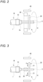
- Fig. 2 is a schematic view of the device for processing an electric wire terminal of the present embodiment as seen from above at a certain point in time
- Fig. 3 is a schematic view as seen from the side at the same point in time as Fig. 2
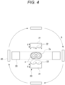
- Fig. 4 is a schematic view as seen from the front.
- Fig. 5 is a front view showing a state before closing a movable plate of the device for processing an electric wire terminal of the present embodiment
- Fig. 6 is a front view showing a state after closing the movable plate
- Fig. 7 is a side view showing the state after closing the movable plate
- Fig. 8 is a side view showing the state when the movable plate is slid.
- the device for processing an electric wire terminal of the present embodiment includes a semi-split glasses-shaped movable plate 20, a detection unit 30, and a rotation mechanism 40, as shown in Figs. 2 to 4 .
- the semi-split glasses-shaped movable plate 20, as shown in Figs. 4 to 6 is provided with a pair of opening and closing plates 21, 21 having two semicircular recesses 22 corresponding to the outer peripheral contours of each half circumference of the pair of exposed wire cores 3, 3 arranged adjacent to each other in a direction orthogonal to the axial direction of the electric wire W, at the opposite edges.
- a protrusion 23 is provided at the boundary between the two adjacent semicircular recesses 22, 22, which is inserted into the recess between the adjacent pair of wire cores 3, 3.
- the pair of opening and closing plates 21, 21 are freely openable and closable in the opening direction where the plates 21, 21 are separated from each other and the closing direction where the plates 21, 21 are close to each other (freely openable and closable in the direction of arrow F in Figs. 3 to 6 ).
- the opening and closing directions are orthogonal to the axial direction of the electric wire.
- This device for processing a terminal is equipped with an opening and closing mechanism (not shown) that drives the pair of opening and closing plates 21, 21 of the movable plate 20 to open and close.
- the movable plate 20 is configured such that, as shown in Fig.
- the movable plate 20 is made of metal or resin (for example, urethane).
- the movable plate 20 is rotatably supported around the axis of the electric wire W, as indicated by the arrow R in Figs. 2 to 4 , and the rotation mechanism 40 functions to rotationally drive the movable plate 20 around the axis of the electric wire W and to position the movable plate 20 in the rotational direction.
- this device for processing a terminal is equipped with a sliding mechanism that pushes the remaining part 2a of the metal foil 2 to the base end side of the electric wire W by sliding the movable plate 20 relatively in the base end direction of the electric wire W, as indicated by arrows S and S1 in Figs. 7 and 8 , in a state where the pair of opening and closing plates 21, 21 are closed.
- the detection unit 30 acquires a lateral projection images of the pair of exposed wire cores 3, 3 while rotating around the pair of exposed wire cores 3, 3, and detects the alignment direction of the pair of wire cores based on the dimensions of the acquired lateral projection images. Specifically, when a laser sensor unit is used as the detection unit 30, laser light is projected toward the pair of exposed wire cores 3, 3, and based on the received light data, a projection image (lateral projection image) of the pair of exposed wire cores 3, 3 viewed from the side is obtained.
- a rotational position where the dimensions of the captured projection image, that is, the dimensions in the direction orthogonal to the axial direction of the electric wire (the apparent width of the two wire cores 3, 3) are minimized is detected as the alignment direction of the pair of exposed wire cores 3, 3.
- a camera that captures the pair of exposed wire cores 3, 3 from the side may be used.
- the rotation mechanism 40 functions to adjust the rotational position of the movable plate 20 such that the opening and closing directions of the pair of opening and closing plates 21, 21 of the movable plate 20 are perpendicular to the alignment direction of the pair of exposed wire cores 3, 3 detected by the detection unit 30. Then, the opening and closing mechanism (not shown) operates the pair of opening and closing plates 21, 21 of the movable plate 20 to close from the open position to the closed position, in a state where the position of the movable plate 20 in the rotational direction is adjusted such that the opening and closing directions of the movable plate 20 are perpendicular to the alignment direction of the pair of wire cores 3, 3.
- the detection unit 30 and the movable plate 20 are provided so as to be fixed to each other at positions shifted by 90° in the rotational direction and rotate integrally. Therefore, since the detection unit 30 stops rotating at the position where the alignment direction of the pair of wire cores 3, 3 is detected, the rotational position is automatically set such that the opening and closing direction of the pair of opening and closing plates 21, 21 of the movable plate 20 are perpendicular to the alignment direction of the wire cores 3, 3. It is desirable that the detection unit 30 and the movable plate 20 be arranged at the same position or as close as possible in the axial direction.
- the detection unit 30 and the rotation mechanism 40 serve as a position adjustment means for adjusting the movable plate 20 to the proper rotational position.
- the device for processing a terminal is equipped with a control unit (not shown) for driving and controlling the detection unit 30, the opening and closing mechanism, the rotation mechanism 40, and the sliding mechanism in coordination.
- a terminal processing portion of the electric wire W (the part indicated by Pw in Fig. 1 ) in which the sheath 1 at the end portion is removed and the metal foil 2 is cut off is set in this device for processing a terminal.
- the electric wire W is held and fixed so as not to rotate. In this state, by rotating the detection unit 30 by the required amount, the alignment direction of the pair of wire cores 3, 3 is automatically detected.
- the detection of the alignment direction of the pair of wire cores 3, 3 is performed as described above. That is, a laser light is projected toward the pair of exposed wire cores 3, 3, and based on the received light data, a projection image (lateral projection image) viewed from the side of the pair of exposed wire cores 3, 3 is captured. Then, the rotational position where the width dimension in the direction orthogonal to the axial direction of the electric wire in the captured projection image (the apparent width of the two wire cores 3, 3) is minimized is detected as the alignment direction of the pair of exposed wire cores 3, 3.
- the opening and closing direction of the pair of opening and closing plates 21, 21 of the movable plate 20 is automatically set to a rotational position that is perpendicular to the alignment direction of the wire cores 3, 3. Therefore, the opening and closing mechanism operates to close the pair of opening and closing plates 21, 21 of the movable plate 20 from the open position to the closed position (operation of arrow F in Figs. 5 and 6).
- Fig. 5 shows a state where the pair of opening and closing plates 21, 21 are in the open position
- Fig. 6 shows a state where the pair of opening and closing plates 21, 21 are in the closed position.
- the semicircular recesses 22 of the pair of opening and closing plates 21, 21 come into close contact with the outer peripheries of the pair of wire cores 3, 3.
- the wire cores 3, 3 can be smoothly fitted into the semicircular recesses 22, 22. Therefore, no undue force is applied to the wire cores 3, 3, and no scratches or indentations are made on the wire cores 3, 3.
- Fig. 7 is a side view of the device for processing an electric wire terminal in this state.
- the movable plate 20 is slid to the base end side of the electric wire W by the sliding mechanism. Then, the remaining part 2a of the metal foil is pushed to the base end side of the electric wire W by the movable plate 20.
- the remaining part 2a of the metal foil occurs on the base end side of the exposed wire cores 3, 3, the remaining part 2a can be pushed to the base end side of the electric wire W by the sliding operation after closing the movable plate 20. Therefore, it is possible to eliminate the adverse effects caused by the remaining part 2a of the metal foil, improve the terminal processing quality, and as a result, contribute to the automation of terminal processing.
- the semicircular recesses 22, 22 of the pair of opening and closing plates 21, 21 can be brought into close contact with the outer periphery of the exposed pair of wire cores 3, 3, so that with a single sliding operation of the movable plate 20, the remaining part 2a of the metal foil can be neatly pushed to the base end side of the electric wire W.
- the detection unit 30 automatically detects the alignment direction of the pair of wire cores 3, 3 and the position of the movable plate 20 is properly adjusted, the remaining part 2a of the metal foil can be easily and efficiently pushed to the base end side of the electric wire W regardless of the orientation of the electric wire W when the electric wire W is inserted into the device.
- the detection unit 30 and the movable plate 20 are configured to rotate integrally, the structure can be simplified.
- the protrusion 23 since the protrusion 23 is left at the boundary of the two semicircular recesses 22, 22 formed in the opening and closing plate 21, the metal foil remaining in the recessed portion between the two wire cores 3, 3 can also be pushed to the base end side of the electric wire by the protrusion 23. At this time, without applying unnecessary force to the opening and closing plates 21, 21, the protrusion 23 can reach the metal foil remaining in the recessed portion between the two wire cores 3, 3, so there is no need to make the contact of the opening and closing plates 21, 21 with the wire cores 3, 3 stronger, and there is no scratches or indentations on the wire cores 3, 3.
- the movable plate 20 is closed at a position slightly away from the sleeve 10, and the movable plate 20 may be slid in the axial direction while being rotated in the direction to untwist the wire cores 3, 3.
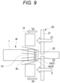
- the bent part 6a of the braid is pushed to the sleeve 10 side by the sliding operation of the movable plate 20 or a similarly shaped movable plate.
- the bent part 6a can be further bent smaller near the sleeve 10, thereby making it possible to form the braid 6 to the specified dimensions. Therefore, all unnecessary items such as the metal foil 2 and the braid 6 at the base of the sleeve 10 can be contained in a compact form, thereby improving the quality of the terminal processing portion.
- the braid 6 may be folded in advance through the sliding operation (operation of arrow S2) of a forming block or a forming sleeve 16 so as to overlap a folded part 6b on the outer periphery of the sleeve 10.
- the bent part 6a of the braid 6 can be strongly pushed into the base end side of the electric wire W, thereby improving the folding dimension quality of the braid 6.
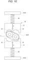
- Fig. 10 is a front view of a device for processing an electric wire terminal according to another embodiment of the present invention
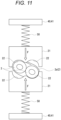
- Fig. 11 is a front view showing a state in the middle of closing the movable plate of the device for processing an electric wire terminal shown in Fig. 10
- Fig. 12 is a front view showing a state where the movable plate of the device for processing an electric wire terminal shown in Fig. 10 is rotated by a predetermined angle
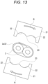
- Fig. 13 is a front view illustrating the shape characteristic points of the movable plate of the device for processing an electric wire terminal shown in Fig. 10 .
- the device for processing a terminal of the present embodiment includes the movable plate 20, but does not include the detection unit.
- the rotation mechanism 40 includes a rotation frame 41 that supports the movable plate 20 via an opening and closing mechanism (not shown), and a spring 50 is interposed between the rotation frame 41 and the movable plate 20 to allow for the escape of the movable plate 20 in the rotational direction.
- the movable plate 20 can be flexibly pressed against the wire cores 3, 3, so the remaining part 2a of the metal foil 2 can be pushed to the base end side of the electric wire without causing scratches or indentations on the wire cores 3, 3. That is, when the pair of opening and closing plates 21, 21 of the movable plate 20 are operated from the open position shown in Fig. 10 to the closed position shown in Fig. 11 , the movable plate 20 comes into contact with the wire cores 3, 3 with some play. Therefore, by sliding the movable plate 20 in a somewhat closed state and repeating the operation several times while changing the rotational position of the movable plate 20 as shown in Fig.
- the remaining part 2a of the metal foil 20 can be pushed to the base end side of the electric wire W.
- the pair of opening and closing plates 21, 21 of the movable plate 20 are designed to escape in the opposite direction by the spring 50 when the plates 21, 21 hit the wire cores 3, 3, so the plates 21, 21 do not damage the wire cores 3, 3.
- the protrusion 23 at the boundary of the two semicircular recesses 22 of the pair of opening and closing plates 21, 21 of the movable plate 20 does not need to fit into the recess between the two wire cores 3, 3, so it is chamfered into a smooth arc shape rather than an acute angle.
- a control unit (not shown) may be configured to allow input of the rotation angle per rotation by the rotation mechanism 40, so that an operator can set the rotation angle per rotation in accordance with the type of electric wire.
Landscapes
- Engineering & Computer Science (AREA)
- Manufacturing & Machinery (AREA)
- Processing Of Terminals (AREA)
- Removal Of Insulation Or Armoring From Wires Or Cables (AREA)
- Manufacturing Of Electrical Connectors (AREA)
Abstract
Description
- The present invention relates to, for example, a device for processing an electric wire terminal and a method for processing an electric wire terminal used in terminal processing of high-speed communication cables and the like.
- As a high-speed communication cable, there is an electromagnetic shield type electric wire in which a pair of wire cores made of a conductor covered with an insulator are arranged, surrounded by metal foil (shielding material) such as aluminum or copper, and covered with a sheath on the outside. In addition, there are also cases where a braid (additional shielding material) is further placed between the metal foil and the sheath. There are also a type with two wire cores arranged in parallel (parallel core type) and a type with two wire cores twisted (twisted core type).
- When performing terminal processing of an electric wire having this type of metal foil as a shielding material, the sheath at the end of the electric wire is removed, the metal foil is cut off, the wire core is exposed, and then the terminal is crimped onto the conductor of the wire core. When there is a braid, the braid is exposed by removing the sheath, the exposed braid is folded back onto the sheath and placed over the end of the sheath, and an earth terminal is crimped onto the part over which the braid is placed. In some cases, a metal sleeve is fitted around the outer periphery of the sheath at the position where the braid is placed.
- By the way, it is desired to automate some or all of the terminal processing of such electric wires. As an example of automating the removal of metal foil, for instance, the technology described in
Patent Literature 1 is known. According to the technology described inPatent Literature 1, the metal foil is cut off by applying a cutting blade to the exposed metal foil after removing the sheath. - Patent Literature 1:
JP5247404B - However, when automatically cutting the metal foil, there is a possibility that a remaining part of the metal foil may occur on the base end side of the exposed wire core. When terminal processing such as terminal crimping is performed in a state where there is a remaining part, short circuits may occur, leading to defective products.
- Therefore, a method can be considered in which no remaining parts occur and it is confirmed whether the metal foil has been completely removed using a camera over the entire circumferential direction of the electric wire. However, in that case, it is necessary to prepare a camera that can identify at least the remaining metal foil on the electric wire, which incurs costs, and there is a problem that it takes time to process the image to determine the presence or absence of the remaining part of a metal foil.
- The present invention has been made in view of the above circumstances, and a purpose of the present invention is to provide a device for processing an electric wire terminal and a method for processing an electric wire terminal that can improve processing quality by eliminating the influence of the remaining part of a metal foil.
- In order to achieve the above-described purpose, a device for processing an electric wire terminal and a method for processing an electric wire terminal according to the present invention are characterized by the following.
- (1) A device for processing an electric wire terminal in which in terminal processing of an end portion of an electric wire having a pair of wire cores of which peripheries are surrounded by a metal foil and a sheath covering an outside the metal foil, in a terminal processing portion of the electric wire in which the sheath at the end portion of the electric wire is removed, the metal foil is removed, and the pair of wire cores are exposed, the device processes a remaining part of the metal foil at a base end of the exposed wire cores, the device including:
- a movable plate that includes a pair of opening and closing plates and is rotatable around an axis of the electric wire, the opening and closing plates having two semicircular recesses each corresponding to an outer peripheral contour of each half circumference of the exposed pair of wire cores, arranged adjacent to each other in a direction orthogonal to the axial direction of the electric wire, on opposite edges and being freely openable and closable in an opening direction in which the opening and closing plates are separated from each other and a closing direction in which the opening and closing plates are close to each other;
- an opening and closing mechanism that drives the pair of opening and closing plates of the movable plate to open and close;
- a rotation mechanism that rotates the movable plate around the axis of the electric wire and positions the movable plate in a rotational direction; and
- a sliding mechanism that pushes the remaining part of the metal foil to the base end side of the electric wire, by sliding the movable plate relatively in a base end direction of the electric wire, in a state where the pair of opening and closing plates are closed.
- (2) A method for processing electric wire terminal, including: a step of, from the electric wire having a pair of wire cores of which a periphery is covered with a metal foil and a sheath, removing the sheath and the metal foil at an end portion of the electric wire;
- a step of closing a pair of opening and closing plates having two semicircular recesses each corresponding to an outer peripheral contour of each half circumference of the exposed pair of wire cores on opposite edges and being freely openable and closable in an opening direction in which the opening and closing plates are separated from each other and a closing direction in which the opening and closing plates are close to each other, at a position of the exposed pair of wire cores, in a state positioned in a rotational direction; and
- a step of pushing a remaining part of the metal foil to the base end side of the electric wire, by sliding the pair of opening and closing plates relatively in a base end direction of the electric wire, in a state where the pair of opening and closing plates are closed.
- According to the present invention, even when the remaining part of the metal foil occurs on the base end side of the exposed wire cores, the remaining part can be pushed to the base end side of the electric wire by the sliding operation after closing the movable plate. Therefore, it is possible to eliminate the adverse effects caused by the remaining part of the metal foil and improve the terminal processing quality. In addition, it can contribute to the automation of terminal processing.
- As described above, the present invention has been briefly described. Furthermore, by thoroughly reading the embodiments (hereinafter referred to as "embodiments") for implementing the invention described below with reference to the accompanying drawings, the details of the present invention will be further clarified.
-
-
Fig. 1 is a perspective view of an electric wire for illustrating a process by a device for processing an electric wire terminal according to an embodiment of the present invention. -
Fig. 2 is a schematic view of the device for processing an electric wire terminal according to the embodiment of the present invention as seen from above. -
Fig. 3 is a schematic view of the device for processing an electric wire terminal according to the embodiment of the present invention as seen from the side. -
Fig. 4 is a schematic view of the device for processing an electric wire terminal according to the embodiment of the present invention as seen from the front. -
Fig. 5 is a front view showing a state before closing a movable plate of the device for processing an electric wire terminal according to the embodiment of the present invention. -
Fig. 6 is a front view showing a state after closing the movable plate of the device for processing an electric wire terminal according to the embodiment of the present invention. -
Fig. 7 is a side view showing a state after closing the movable plate of the device for processing an electric wire terminal according to the embodiment of the present invention. -
Fig. 8 is a side view showing a state when the movable plate of the device for processing an electric wire terminal according to the embodiment of the present invention is slid. -
Fig. 9 is a side view of a device for processing an electric wire terminal according to another embodiment of the present invention. -
Fig. 10 is a front view of a device for processing an electric wire terminal according to yet another embodiment of the present invention. -
Fig. 11 is a front view showing a state in the middle of closing the movable plate of the device for processing an electric wire terminal shown inFig. 10 . -
Fig. 12 is a front view showing a state when the movable plate of the device for processing an electric wire terminal shown inFig. 10 is rotated by a predetermined angle. -
Fig. 13 is a front view for illustrating the shape characteristic points of the movable plate of the device for processing an electric wire terminal shown inFig. 10 . - The specific embodiments of the present invention will be described below with reference to the drawings.
-
Fig. 1 is a perspective view of an electric wire for illustrating a process by a device for processing an electric wire terminal according to an embodiment of the present invention. - The device for processing an electric wire terminal in this embodiment is, as an example, intended to process an electric wire W as shown in the upper and lower parts on the left side of
Fig. 1 . In this electric wire W, the periphery of a pair of (two)wire cores 3 is surrounded by ametal foil 2 such as aluminum or copper, and the outside is covered with asheath 1 of an insulating material. Eachwire core 3 is made of aconductor 4 surrounded by aninsulator 5, and themetal foil 2 covers the periphery of the pair ofwire cores wire cores 3 extend parallel to each other, and the bottom left part shows a wire B of the twisted core type in which twowire cores 3 are twisted together. The device for processing a terminal of the present embodiment is intended to process the electric wire W of both types: the parallel core type and the twisted core type. In addition, the device for processing an electric wire terminal of the present embodiment is intended to process electric wires with a structure in which a braid is further disposed between themetal foil 2 and thesheath 1, as described later. - In the device for processing a terminal of this embodiment, in terminal processing of an end portion of such an electric wire W, the device processes a
remaining part 2a of themetal foil 2 at a base end of the exposedwire cores 3, in a terminal processing portion Pw of the electric wire in which thesheath 1 andmetal foil 2 at the end portion of the electric wire W are removed and the pair of wire cores are exposed. In many cases, before processing with this device for processing a terminal, a metalcylindrical sleeve 10 is crimped onto the outer periphery of the end portion of thesheath 1. - The device for processing a terminal of the present embodiment performs a process of pushing the
remaining part 2a of themetal foil 2 at the terminal processing portion Pw of the electric wire to the base end side of the electric wire W (the side with the sleeve 10) as shown in C in the right part ofFig. 1 . -
Fig. 2 is a schematic view of the device for processing an electric wire terminal of the present embodiment as seen from above at a certain point in time,Fig. 3 is a schematic view as seen from the side at the same point in time asFig. 2 , andFig. 4 is a schematic view as seen from the front. In addition,Fig. 5 is a front view showing a state before closing a movable plate of the device for processing an electric wire terminal of the present embodiment,Fig. 6 is a front view showing a state after closing the movable plate,Fig. 7 is a side view showing the state after closing the movable plate, andFig. 8 is a side view showing the state when the movable plate is slid. - The device for processing an electric wire terminal of the present embodiment includes a semi-split glasses-shaped
movable plate 20, adetection unit 30, and arotation mechanism 40, as shown inFigs. 2 to 4 . - The semi-split glasses-shaped
movable plate 20, as shown inFigs. 4 to 6 , is provided with a pair of opening andclosing plates semicircular recesses 22 corresponding to the outer peripheral contours of each half circumference of the pair of exposedwire cores protrusion 23 is provided at the boundary between the two adjacentsemicircular recesses wire cores - The pair of opening and
closing plates plates plates Figs. 3 to 6 ). The opening and closing directions are orthogonal to the axial direction of the electric wire. This device for processing a terminal is equipped with an opening and closing mechanism (not shown) that drives the pair of opening andclosing plates movable plate 20 to open and close. Themovable plate 20 is configured such that, as shown inFig. 6 , when the pair of opening andclosing plates semicircular recesses wire cores movable plate 20 is made of metal or resin (for example, urethane). - The
movable plate 20 is rotatably supported around the axis of the electric wire W, as indicated by the arrow R inFigs. 2 to 4 , and therotation mechanism 40 functions to rotationally drive themovable plate 20 around the axis of the electric wire W and to position themovable plate 20 in the rotational direction. In addition, this device for processing a terminal is equipped with a sliding mechanism that pushes the remainingpart 2a of themetal foil 2 to the base end side of the electric wire W by sliding themovable plate 20 relatively in the base end direction of the electric wire W, as indicated by arrows S and S1 inFigs. 7 and 8 , in a state where the pair of opening andclosing plates - The
detection unit 30 acquires a lateral projection images of the pair of exposedwire cores wire cores detection unit 30, laser light is projected toward the pair of exposedwire cores wire cores wire cores 3, 3) are minimized is detected as the alignment direction of the pair of exposedwire cores wire cores - The
rotation mechanism 40 functions to adjust the rotational position of themovable plate 20 such that the opening and closing directions of the pair of opening andclosing plates movable plate 20 are perpendicular to the alignment direction of the pair of exposedwire cores detection unit 30. Then, the opening and closing mechanism (not shown) operates the pair of opening andclosing plates movable plate 20 to close from the open position to the closed position, in a state where the position of themovable plate 20 in the rotational direction is adjusted such that the opening and closing directions of themovable plate 20 are perpendicular to the alignment direction of the pair ofwire cores - In the present embodiment, the
detection unit 30 and themovable plate 20 are provided so as to be fixed to each other at positions shifted by 90° in the rotational direction and rotate integrally. Therefore, since thedetection unit 30 stops rotating at the position where the alignment direction of the pair ofwire cores closing plates movable plate 20 are perpendicular to the alignment direction of thewire cores detection unit 30 and themovable plate 20 be arranged at the same position or as close as possible in the axial direction. - In the present embodiment, the
detection unit 30 and therotation mechanism 40 serve as a position adjustment means for adjusting themovable plate 20 to the proper rotational position. The device for processing a terminal is equipped with a control unit (not shown) for driving and controlling thedetection unit 30, the opening and closing mechanism, therotation mechanism 40, and the sliding mechanism in coordination. - Next, the operation will be described.
- As preparation for the processing work, a terminal processing portion of the electric wire W (the part indicated by Pw in
Fig. 1 ) in which thesheath 1 at the end portion is removed and themetal foil 2 is cut off is set in this device for processing a terminal. At this time, the electric wire W is held and fixed so as not to rotate. In this state, by rotating thedetection unit 30 by the required amount, the alignment direction of the pair ofwire cores - When a laser sensor unit is employed as the
detection unit 30, the detection of the alignment direction of the pair ofwire cores wire cores wire cores wire cores 3, 3) is minimized is detected as the alignment direction of the pair of exposedwire cores - When the rotation of the
detection unit 30 is stopped at the position where the alignment direction of the pair ofwire cores Fig. 5 , the opening and closing direction of the pair of opening andclosing plates movable plate 20 is automatically set to a rotational position that is perpendicular to the alignment direction of thewire cores closing plates movable plate 20 from the open position to the closed position (operation of arrow F inFigs. 5 and 6). Fig. 5 shows a state where the pair of opening andclosing plates Fig. 6 shows a state where the pair of opening andclosing plates Fig. 6 , thesemicircular recesses 22 of the pair of opening andclosing plates wire cores wire cores semicircular recesses wire cores wire cores -
Fig. 7 is a side view of the device for processing an electric wire terminal in this state. In this state, as shown inFig. 8 , themovable plate 20 is slid to the base end side of the electric wire W by the sliding mechanism. Then, the remainingpart 2a of the metal foil is pushed to the base end side of the electric wire W by themovable plate 20. - In this way, even when the remaining
part 2a of the metal foil occurs on the base end side of the exposedwire cores part 2a can be pushed to the base end side of the electric wire W by the sliding operation after closing themovable plate 20. Therefore, it is possible to eliminate the adverse effects caused by the remainingpart 2a of the metal foil, improve the terminal processing quality, and as a result, contribute to the automation of terminal processing. - In this embodiment in particular, when the
movable plate 20 is closed, thesemicircular recesses closing plates wire cores movable plate 20, the remainingpart 2a of the metal foil can be neatly pushed to the base end side of the electric wire W. - In addition, according to this embodiment, since the
detection unit 30 automatically detects the alignment direction of the pair ofwire cores movable plate 20 is properly adjusted, the remainingpart 2a of the metal foil can be easily and efficiently pushed to the base end side of the electric wire W regardless of the orientation of the electric wire W when the electric wire W is inserted into the device. - Further, in this embodiment, since the
detection unit 30 and themovable plate 20 are configured to rotate integrally, the structure can be simplified. - In this embodiment, since the
protrusion 23 is left at the boundary of the twosemicircular recesses plate 21, the metal foil remaining in the recessed portion between the twowire cores protrusion 23. At this time, without applying unnecessary force to the opening andclosing plates protrusion 23 can reach the metal foil remaining in the recessed portion between the twowire cores closing plates wire cores wire cores - In the case where the electric wire to be processed is of the twisted core type, the
movable plate 20 is closed at a position slightly away from thesleeve 10, and themovable plate 20 may be slid in the axial direction while being rotated in the direction to untwist thewire cores - Further, as shown in
Fig. 9 , when thebraid 6, which has been pre-folded, is in the terminal processing portion, thebent part 6a of the braid is pushed to thesleeve 10 side by the sliding operation of themovable plate 20 or a similarly shaped movable plate. In this way, thebent part 6a can be further bent smaller near thesleeve 10, thereby making it possible to form thebraid 6 to the specified dimensions. Therefore, all unnecessary items such as themetal foil 2 and thebraid 6 at the base of thesleeve 10 can be contained in a compact form, thereby improving the quality of the terminal processing portion. Thebraid 6 may be folded in advance through the sliding operation (operation of arrow S2) of a forming block or a formingsleeve 16 so as to overlap a foldedpart 6b on the outer periphery of thesleeve 10. - In this way, by the pressing operation of the metal foil by the
movable plate 20, thebent part 6a of thebraid 6 can be strongly pushed into the base end side of the electric wire W, thereby improving the folding dimension quality of thebraid 6. -
Fig. 10 is a front view of a device for processing an electric wire terminal according to another embodiment of the present invention,Fig. 11 is a front view showing a state in the middle of closing the movable plate of the device for processing an electric wire terminal shown inFig. 10 ,Fig. 12 is a front view showing a state where the movable plate of the device for processing an electric wire terminal shown inFig. 10 is rotated by a predetermined angle, andFig. 13 is a front view illustrating the shape characteristic points of the movable plate of the device for processing an electric wire terminal shown inFig. 10 . - As shown in
Figs. 10 to 12 , the device for processing a terminal of the present embodiment includes themovable plate 20, but does not include the detection unit. Then, therotation mechanism 40 includes a rotation frame 41 that supports themovable plate 20 via an opening and closing mechanism (not shown), and aspring 50 is interposed between the rotation frame 41 and themovable plate 20 to allow for the escape of themovable plate 20 in the rotational direction. - In this device, due to the action of the
spring 50, themovable plate 20 can be flexibly pressed against thewire cores part 2a of themetal foil 2 can be pushed to the base end side of the electric wire without causing scratches or indentations on thewire cores closing plates movable plate 20 are operated from the open position shown inFig. 10 to the closed position shown inFig. 11 , themovable plate 20 comes into contact with thewire cores movable plate 20 in a somewhat closed state and repeating the operation several times while changing the rotational position of themovable plate 20 as shown inFig. 12 , the remainingpart 2a of themetal foil 20 can be pushed to the base end side of the electric wire W. In this case, the pair of opening andclosing plates movable plate 20 are designed to escape in the opposite direction by thespring 50 when theplates wire cores plates wire cores Fig. 13 , theprotrusion 23 at the boundary of the twosemicircular recesses 22 of the pair of opening andclosing plates movable plate 20 does not need to fit into the recess between the twowire cores - In the above-described embodiment, the case is shown where the electric wire is fixed so as not to rotate and the
movable plate 20 is rotated, but it is also possible to rotate the electric wire W instead of rotating themovable plate 20. In addition, a control unit (not shown) may be configured to allow input of the rotation angle per rotation by therotation mechanism 40, so that an operator can set the rotation angle per rotation in accordance with the type of electric wire. - Here, the features of the device for processing an electric wire terminal and the method for processing an electric wire terminal according to the embodiment of the present invention described above are briefly summarized and listed below [1] to [6].
- [1] A device for processing an electric wire terminal in which, in an electric wire (W) having a pair of wire cores (3, 3) of which a periphery is covered with a metal foil (2) and a sheath (1), in a state where the sheath (1) and the metal foil (2) at an end portion of the electric wire (W) are removed and the wire cores (3, 3) are exposed, the device processes a remaining part (2a) of the metal foil at a base end of the exposed wire cores (3, 3), the device including:
- a movable plate (20) that includes a pair of opening and closing plates (21, 21) and is rotatable around an axis of the electric wire, the opening and closing plates (21, 21) having two semicircular recesses (22, 22) each corresponding to an outer peripheral contour of each half circumference of the exposed pair of wire cores (3, 3) on opposite edges and being freely openable and closable in an opening direction in which the opening and closing plates (21, 21) are separated from each other and a closing direction in which the opening and closing plates (21, 21) are close to each other;
- an opening and closing mechanism that drives the pair of opening and closing plates (21, 21) to open and close;
- a rotation mechanism (40) that rotates the movable plate (20) around the axis of the electric wire (W) and positions the movable plate (20) in a rotational direction; and
- a sliding mechanism that pushes the remaining part (2a) of the metal foil to the base end side of the electric wire (W), by sliding the movable plate (20) relatively in a base end direction of the electric wire (W), in a state where the pair of opening and closing plates (21, 21) are closed.
- [2] The device for processing an electric wire terminal according to the above [1], in which
- the movable plate (20) is configured to bring the two semicircular recesses (22, 22) into close contact with the outer periphery of the pair of exposed wire cores (3, 3) arranged adjacent to each other, when the pair of opening and closing plates (21, 21) are closed,
- the movable plate (20) is supported via a position adjustment means for adjusting a relative position of the electric wire (W) and the movable plate (20) in a circumferential direction such that the opening and closing directions of the pair of opening and closing plates (21, 21) are perpendicular to an alignment direction of the pair of exposed wire cores (3, 3), and
- the opening and closing mechanism operates the pair of opening and closing plates (21, 21) of the movable plate (20) to close from an open position to a closed position, in a state where the relative position of the electric wire (W) and the movable plate (20) in the circumferential direction is adjusted such that the opening and closing directions of the movable plate (20) are perpendicular to the alignment direction of the pair of wire cores (3, 3).
- [3] The device for processing an electric wire terminal according to the above [2], in which
- the position adjustment means includes a detection unit (30) that acquires a lateral projection image of the pair of exposed wire cores while rotating around the pair of exposed wire cores, and detects the alignment direction of the pair of wire cores based on a dimension of the acquired lateral projection image, and
- the rotation mechanism (40) adjusts a rotational position of the movable plate (20) such that the opening and closing directions of the pair of opening and closing plates (21, 21) of the movable plate (20) are perpendicular to the alignment direction of the pair of exposed wire cores (3, 3) detected by the detection unit (30).
- [4] The device for processing an electric wire terminal according to the above [3], in which
- the detection unit (30) and the movable plate (20) are provided so as to be fixed to each other at positions shifted by 90° in the rotational direction and rotate integrally,
- the detection unit (30) detects a rotational position where a dimension of the lateral projection image of the pair of exposed wire cores (3, 3) in the direction orthogonal to an axial direction of the electric wire (W) is minimized, as the alignment direction of the pair of exposed wire cores (3, 3), and
- the rotation mechanism (40) adjusts a rotational position of the movable plate (20) such that the opening and closing directions of the pair of opening and closing plates (21, 21) of the movable plate (20) are perpendicular to the alignment direction of the pair of exposed wire cores (3, 3) detected by the detection unit (30).
- [5] The device for processing an electric wire terminal according to any of the above [1] to [4], in which the electric wire (W) is configured to include a braid (6) between the metal foil (2) and the sheath (1), and
the movable plate (20) is slid in the base end direction of the electric wire (W) to cause the remaining part (2a) of the metal foil and a bent part (6a) of the braid (6) to be pushed together to the base end side of the electric wire (W).
According to the configuration of the above [5], the pushing operation of the remaining part (2a) of the metal foil by the movable plate (20) causes the bent part (6a) of the braid to be strongly pushed to the base end side of the electric wire (W), thereby improving the quality of the braid's folding dimensions. - [6] A method for processing electric wire terminal, including:
- a step of, from an electric wire (W) having a pair of wire cores (3, 3) of which a periphery is covered with a metal foil (2) and a sheath (1), removing the sheath (1) and the metal foil (2) at an end portion of the electric wire;
- a step of closing a pair of opening and closing plates (21, 21) having two semicircular recesses (22, 22) each corresponding to an outer peripheral contour of each half circumference of the exposed pair of wire cores (3, 3) on opposite edges and being freely openable and closable in an opening direction in which the opening and closing plates (21, 21) are separated from each other and a closing direction in which the opening and closing plates (21, 21) are close to each other, at a position of the exposed pair of wire cores (3, 3), in a state positioned in a rotational direction; and
- a step of pushing the remaining part (2a) of the metal foil to the base end side of the electric wire (W), by sliding the pair of opening and closing plates relatively in a base end direction of the electric wire (W), in a state where the pair of opening and closing plates (21, 21) are closed.
- According to the configuration of the above [6], even when the remaining part (2a) of the metal foil occurs on the base end side of the exposed wire cores (3, 3), the remaining part (2a) can be pushed to the base end side of the electric wire (W). Therefore, it is possible to eliminate the adverse effects caused by the remaining part (2a) of the metal foil and improve the terminal processing quality.
- The present invention is not limited to the embodiments described above, and various modifications, improvements, and the like can be made as appropriate. In addition, the material, shape, dimensions, number, placement locations, etc. of each component in the above-described embodiments are arbitrary as long as the present invention can be achieved and are not limited.
- As described above, various embodiments have been described with reference to the drawings, but it goes without saying that the present invention is not limited to such examples. It is evident that those skilled in the art can come up with various modifications or alterations within the scope described in the claims, and it is understood that these also naturally fall within the technical scope of the present invention. In addition, within the scope not deviating from the gist of the invention, the respective components in the above embodiment may be combined arbitrarily.
- This application is based on
Japanese Patent Application No. 2022-119625, filed on July 27, 2022 -
- 1 Sheath
- 2. Metal foil
- 2a Remaining part of metal foil
- 3 Wire core
- 6 Braid
- 20 Movable plate
- 21 Opening and closing plate
- 22 Semicircular recess
- 30 Detection unit
- 40 Rotation mechanism
- 41 Rotation frame
- 50 Spring
- W Electric wire
- Pw Terminal processing portion
Claims (6)
- A device for processing an electric wire terminal in which, in an electric wire having a pair of wire cores of which a periphery is covered with a metal foil and a sheath, in a state where the sheath and the metal foil at an end portion of the electric wire are removed and the wire cores are exposed, the device processes a remaining part of the metal foil at a base end of the exposed wire cores, the device comprising:a movable plate that includes a pair of opening and closing plates and is rotatable around an axis of the electric wire, the opening and closing plates having two semicircular recesses each corresponding to an outer peripheral contour of each half circumference of the exposed pair of wire cores on opposite edges and being freely openable and closable in an opening direction in which the opening and closing plates are separated from each other and a closing direction in which the opening and closing plates are close to each other;an opening and closing mechanism that drives the pair of opening and closing plates to open and close;a rotation mechanism that rotates the movable plate around the axis of the electric wire and positions the movable plate in a rotational direction; anda sliding mechanism that pushes the remaining part of the metal foil to the base end side of the electric wire, by sliding the movable plate relatively in a base end direction of the electric wire, in a state where the pair of opening and closing plates are closed.
- The device for processing an electric wire terminal according to claim 1, whereinthe movable plate is configured to bring the two semicircular recesses into close contact with the outer periphery of the pair of exposed wire cores arranged adjacent to each other, when the pair of opening and closing plates are closed,the movable plate is supported via a position adjustment means for adjusting a relative position of the electric wire and the movable plate in a circumferential direction such that opening and closing directions of the pair of opening and closing plates are perpendicular to an alignment direction of the pair of exposed wire cores, andthe opening and closing mechanism operates the pair of opening and closing plates of the movable plate to close from an open position to a closed position, in a state where the relative position of the electric wire and the movable plate in the circumferential direction is adjusted such that the opening and closing directions of the movable plate are perpendicular to the alignment direction of the pair of exposed wire cores.
- The device for processing an electric wire terminal according to claim 2, whereinthe position adjustment meansincludes a detection unit that acquires a lateral projection image of the pair of exposed wire cores while rotating around the pair of exposed wire cores, and detects the alignment direction of the pair of wire cores based on a dimension of the acquired lateral projection image, andthe rotation mechanism adjusts a rotational position of the movable plate such that the opening and closing directions of the pair of opening and closing plates of the movable plate are perpendicular to the alignment direction of the pair of exposed wire cores detected by the detection unit.
- The device for processing an electric wire terminal according to claim 3, whereinthe detection unit and the movable plate are provided so as to be fixed to each other at positions shifted by 90° in the rotational direction and rotate integrally,the detection unit detects a rotational position where a dimension of the lateral projection image of the pair of exposed wire cores in the direction orthogonal to an axial direction of the electric wire is minimized, as the alignment direction of the pair of exposed wire cores, andthe rotation mechanism adjusts the rotational position of the movable plate such that the opening and closing directions of the pair of opening and closing plates of the movable plate are perpendicular to the alignment direction of the pair of exposed wire cores detected by the detection unit.
- The device for processing an electric wire terminal according to claim 1, whereinthe electric wire is configured to include a braid between the metal foil and the sheath, andthe movable plate is slid in the base end direction of the electric wire to cause the remaining part of the metal foil and a bent part of the braid to be pushed together to the base end side of the electric wire.
- A method for processing electric wire terminal, comprising:a step of, from an electric wire having a pair of wire cores of which a periphery is covered with a metal foil and a sheath, removing the sheath and the metal foil at an end portion of the electric wire;a step of closing a pair of opening and closing plates having two semicircular recesses each corresponding to an outer peripheral contour of each half circumference of the exposed pair of wire cores on opposite edges and being freely openable and closable in an opening direction in which the opening and closing plates are separated from each other and a closing direction in which the opening and closing plates are close to each other, at a position of the exposed pair of wire cores, in a state positioned in a rotational direction; anda step of pushing the remaining part of the metal foil to the base end side of the electric wire, by sliding the pair of opening and closing plates relatively in a base end direction of the electric wire, in a state where the pair of opening and closing plates are closed.
Applications Claiming Priority (2)
| Application Number | Priority Date | Filing Date | Title |
|---|---|---|---|
| JP2022119625A JP7787032B2 (en) | 2022-07-27 | 2022-07-27 | Wire end processing equipment |
| PCT/JP2023/023683 WO2024024367A1 (en) | 2022-07-27 | 2023-06-26 | Device and method for processing electric wire terminal |
Publications (2)
| Publication Number | Publication Date |
|---|---|
| EP4564622A1 true EP4564622A1 (en) | 2025-06-04 |
| EP4564622A4 EP4564622A4 (en) | 2025-11-19 |
Family
ID=89706040
Family Applications (1)
| Application Number | Title | Priority Date | Filing Date |
|---|---|---|---|
| EP23846101.6A Pending EP4564622A4 (en) | 2022-07-27 | 2023-06-26 | DEVICE AND METHOD FOR PROCESSING AN ELECTRICAL WIRE CONNECTION |
Country Status (5)
| Country | Link |
|---|---|
| EP (1) | EP4564622A4 (en) |
| JP (1) | JP7787032B2 (en) |
| CN (1) | CN119404397A (en) |
| MX (1) | MX2024015936A (en) |
| WO (1) | WO2024024367A1 (en) |
Family Cites Families (8)
| Publication number | Priority date | Publication date | Assignee | Title |
|---|---|---|---|---|
| JP2002262429A (en) * | 2001-03-02 | 2002-09-13 | Yazaki Corp | Shield wire braiding device and braid folding method |
| JP2004120992A (en) | 2002-09-26 | 2004-04-15 | Masashi Hayamizu | Stripping tool of vvf cable coatings that simultaneously performs two-step stripping processes of coatings |
| JP5247404B2 (en) | 2008-12-12 | 2013-07-24 | 矢崎総業株式会社 | Cutting blade unit |
| JP2012050169A (en) * | 2010-08-24 | 2012-03-08 | Auto Network Gijutsu Kenkyusho:Kk | Terminal processing method of shielded cable |
| EP3322054B1 (en) * | 2016-11-15 | 2020-06-03 | Schleuniger Holding AG | Apparatus and method for removing an internal envelope from an electrical conductor |
| DE102019119663A1 (en) * | 2019-04-24 | 2021-01-21 | Metzner Maschinenbau Gmbh | Method, device and system for assembling an electrical cable |
| JP7104090B2 (en) | 2020-03-19 | 2022-07-20 | 矢崎総業株式会社 | Sheath removal device and sheath removal method |
| JP2022119625A (en) | 2021-02-04 | 2022-08-17 | 冨士色素株式会社 | Conductive auxiliary agent and method for producing the same |
-
2022
- 2022-07-27 JP JP2022119625A patent/JP7787032B2/en active Active
-
2023
- 2023-06-26 WO PCT/JP2023/023683 patent/WO2024024367A1/en not_active Ceased
- 2023-06-26 EP EP23846101.6A patent/EP4564622A4/en active Pending
- 2023-06-26 CN CN202380048472.1A patent/CN119404397A/en active Pending
-
2024
- 2024-12-18 MX MX2024015936A patent/MX2024015936A/en unknown
Also Published As
| Publication number | Publication date |
|---|---|
| MX2024015936A (en) | 2025-02-10 |
| JP7787032B2 (en) | 2025-12-16 |
| EP4564622A4 (en) | 2025-11-19 |
| WO2024024367A1 (en) | 2024-02-01 |
| CN119404397A (en) | 2025-02-07 |
| JP2024017162A (en) | 2024-02-08 |
Similar Documents
| Publication | Publication Date | Title |
|---|---|---|
| EP3618207B2 (en) | Cable braid flare mechanism for cable preparation machine | |
| EP4231471B1 (en) | Cable preparation machine | |
| CN103887740B (en) | Method and apparatus for removing a shield from a cable | |
| JP6794128B2 (en) | Cable processing equipment and methods for removing shielding film from shielded multi-core round cables | |
| US11056852B2 (en) | Cable preparation machine | |
| US12027832B2 (en) | Method for removing shield foil and shield foil removing device | |
| JP6336942B2 (en) | Bundle processing machine | |
| EP4564623A1 (en) | Terminal processing device for electric wire | |
| US11715923B2 (en) | Metal foil flaring apparatus | |
| CN107959265B (en) | Method and device for stripping cables having a multilayer sheath | |
| US3484936A (en) | Sleeve assembling and insulation stripping apparatus for coaxial cable | |
| CN113224693A (en) | Fabric cutting apparatus and fabric cutting method | |
| CN114026757A (en) | Method and apparatus for producing electric cable | |
| WO2018198757A1 (en) | End setting device and end processing device | |
| JP2018185983A (en) | Un-twining device and wire end part processor | |
| JP6929902B2 (en) | Braid folding device for the end of the coaxial wire | |
| JP7157100B2 (en) | Braid cuff cutting device and braid cuff cutting method | |
| JP7787032B2 (en) | Wire end processing equipment | |
| US20030196520A1 (en) | Stripping device and a method for stripping | |
| JP2003032825A (en) | Wire stripping method and stripping device | |
| JP5351726B2 (en) | Cable covering material removing apparatus and cable covering material removing method | |
| JP2005328649A (en) | Shielded cable terminal processing apparatus and method | |
| JPH04331407A (en) | Wire stripper machine | |
| WO2025004929A1 (en) | Electric cable processing device | |
| JPH0595122U (en) | Cut and peeling structure of wire sheath removal device |
Legal Events
| Date | Code | Title | Description |
|---|---|---|---|
| STAA | Information on the status of an ep patent application or granted ep patent |
Free format text: STATUS: THE INTERNATIONAL PUBLICATION HAS BEEN MADE |
|
| PUAI | Public reference made under article 153(3) epc to a published international application that has entered the european phase |
Free format text: ORIGINAL CODE: 0009012 |
|
| STAA | Information on the status of an ep patent application or granted ep patent |
Free format text: STATUS: REQUEST FOR EXAMINATION WAS MADE |
|
| 17P | Request for examination filed |
Effective date: 20241218 |
|
| AK | Designated contracting states |
Kind code of ref document: A1 Designated state(s): AL AT BE BG CH CY CZ DE DK EE ES FI FR GB GR HR HU IE IS IT LI LT LU LV MC ME MK MT NL NO PL PT RO RS SE SI SK SM TR |
|
| DAV | Request for validation of the european patent (deleted) | ||
| DAX | Request for extension of the european patent (deleted) | ||
| A4 | Supplementary search report drawn up and despatched |
Effective date: 20251022 |
|
| RIC1 | Information provided on ipc code assigned before grant |
Ipc: H02G 1/12 20060101AFI20251016BHEP Ipc: H02G 1/14 20060101ALI20251016BHEP Ipc: H01R 43/28 20060101ALI20251016BHEP |
|
| GRAP | Despatch of communication of intention to grant a patent |
Free format text: ORIGINAL CODE: EPIDOSNIGR1 |
|
| STAA | Information on the status of an ep patent application or granted ep patent |
Free format text: STATUS: GRANT OF PATENT IS INTENDED |