EP4564578A1 - Separator, battery and electrical device - Google Patents
Separator, battery and electrical device Download PDFInfo
- Publication number
- EP4564578A1 EP4564578A1 EP23905318.4A EP23905318A EP4564578A1 EP 4564578 A1 EP4564578 A1 EP 4564578A1 EP 23905318 A EP23905318 A EP 23905318A EP 4564578 A1 EP4564578 A1 EP 4564578A1
- Authority
- EP
- European Patent Office
- Prior art keywords
- separator
- battery
- positive electrode
- negative electrode
- electrode plate
- Prior art date
- Legal status (The legal status is an assumption and is not a legal conclusion. Google has not performed a legal analysis and makes no representation as to the accuracy of the status listed.)
- Pending
Links
Images



Classifications
-
- H—ELECTRICITY
- H01—ELECTRIC ELEMENTS
- H01M—PROCESSES OR MEANS, e.g. BATTERIES, FOR THE DIRECT CONVERSION OF CHEMICAL ENERGY INTO ELECTRICAL ENERGY
- H01M50/00—Constructional details or processes of manufacture of the non-active parts of electrochemical cells other than fuel cells, e.g. hybrid cells
- H01M50/40—Separators; Membranes; Diaphragms; Spacing elements inside cells
- H01M50/489—Separators, membranes, diaphragms or spacing elements inside the cells, characterised by their physical properties, e.g. swelling degree, hydrophilicity or shut down properties
- H01M50/491—Porosity
-
- H—ELECTRICITY
- H01—ELECTRIC ELEMENTS
- H01M—PROCESSES OR MEANS, e.g. BATTERIES, FOR THE DIRECT CONVERSION OF CHEMICAL ENERGY INTO ELECTRICAL ENERGY
- H01M50/00—Constructional details or processes of manufacture of the non-active parts of electrochemical cells other than fuel cells, e.g. hybrid cells
- H01M50/40—Separators; Membranes; Diaphragms; Spacing elements inside cells
- H01M50/463—Separators, membranes or diaphragms characterised by their shape
-
- H—ELECTRICITY
- H01—ELECTRIC ELEMENTS
- H01M—PROCESSES OR MEANS, e.g. BATTERIES, FOR THE DIRECT CONVERSION OF CHEMICAL ENERGY INTO ELECTRICAL ENERGY
- H01M10/00—Secondary cells; Manufacture thereof
- H01M10/05—Accumulators with non-aqueous electrolyte
- H01M10/052—Li-accumulators
- H01M10/0525—Rocking-chair batteries, i.e. batteries with lithium insertion or intercalation in both electrodes; Lithium-ion batteries
-
- H—ELECTRICITY
- H01—ELECTRIC ELEMENTS
- H01M—PROCESSES OR MEANS, e.g. BATTERIES, FOR THE DIRECT CONVERSION OF CHEMICAL ENERGY INTO ELECTRICAL ENERGY
- H01M50/00—Constructional details or processes of manufacture of the non-active parts of electrochemical cells other than fuel cells, e.g. hybrid cells
- H01M50/40—Separators; Membranes; Diaphragms; Spacing elements inside cells
- H01M50/409—Separators, membranes or diaphragms characterised by the material
- H01M50/411—Organic material
- H01M50/414—Synthetic resins, e.g. thermoplastics or thermosetting resins
- H01M50/417—Polyolefins
-
- H—ELECTRICITY
- H01—ELECTRIC ELEMENTS
- H01M—PROCESSES OR MEANS, e.g. BATTERIES, FOR THE DIRECT CONVERSION OF CHEMICAL ENERGY INTO ELECTRICAL ENERGY
- H01M50/00—Constructional details or processes of manufacture of the non-active parts of electrochemical cells other than fuel cells, e.g. hybrid cells
- H01M50/40—Separators; Membranes; Diaphragms; Spacing elements inside cells
- H01M50/409—Separators, membranes or diaphragms characterised by the material
- H01M50/411—Organic material
- H01M50/414—Synthetic resins, e.g. thermoplastics or thermosetting resins
- H01M50/426—Fluorocarbon polymers
-
- H—ELECTRICITY
- H01—ELECTRIC ELEMENTS
- H01M—PROCESSES OR MEANS, e.g. BATTERIES, FOR THE DIRECT CONVERSION OF CHEMICAL ENERGY INTO ELECTRICAL ENERGY
- H01M50/00—Constructional details or processes of manufacture of the non-active parts of electrochemical cells other than fuel cells, e.g. hybrid cells
- H01M50/40—Separators; Membranes; Diaphragms; Spacing elements inside cells
- H01M50/409—Separators, membranes or diaphragms characterised by the material
- H01M50/431—Inorganic material
-
- H—ELECTRICITY
- H01—ELECTRIC ELEMENTS
- H01M—PROCESSES OR MEANS, e.g. BATTERIES, FOR THE DIRECT CONVERSION OF CHEMICAL ENERGY INTO ELECTRICAL ENERGY
- H01M50/00—Constructional details or processes of manufacture of the non-active parts of electrochemical cells other than fuel cells, e.g. hybrid cells
- H01M50/40—Separators; Membranes; Diaphragms; Spacing elements inside cells
- H01M50/409—Separators, membranes or diaphragms characterised by the material
- H01M50/431—Inorganic material
- H01M50/434—Ceramics
-
- H—ELECTRICITY
- H01—ELECTRIC ELEMENTS
- H01M—PROCESSES OR MEANS, e.g. BATTERIES, FOR THE DIRECT CONVERSION OF CHEMICAL ENERGY INTO ELECTRICAL ENERGY
- H01M50/00—Constructional details or processes of manufacture of the non-active parts of electrochemical cells other than fuel cells, e.g. hybrid cells
- H01M50/40—Separators; Membranes; Diaphragms; Spacing elements inside cells
- H01M50/409—Separators, membranes or diaphragms characterised by the material
- H01M50/44—Fibrous material
-
- H—ELECTRICITY
- H01—ELECTRIC ELEMENTS
- H01M—PROCESSES OR MEANS, e.g. BATTERIES, FOR THE DIRECT CONVERSION OF CHEMICAL ENERGY INTO ELECTRICAL ENERGY
- H01M50/00—Constructional details or processes of manufacture of the non-active parts of electrochemical cells other than fuel cells, e.g. hybrid cells
- H01M50/40—Separators; Membranes; Diaphragms; Spacing elements inside cells
- H01M50/409—Separators, membranes or diaphragms characterised by the material
- H01M50/446—Composite material consisting of a mixture of organic and inorganic materials
-
- H—ELECTRICITY
- H01—ELECTRIC ELEMENTS
- H01M—PROCESSES OR MEANS, e.g. BATTERIES, FOR THE DIRECT CONVERSION OF CHEMICAL ENERGY INTO ELECTRICAL ENERGY
- H01M50/00—Constructional details or processes of manufacture of the non-active parts of electrochemical cells other than fuel cells, e.g. hybrid cells
- H01M50/40—Separators; Membranes; Diaphragms; Spacing elements inside cells
- H01M50/409—Separators, membranes or diaphragms characterised by the material
- H01M50/449—Separators, membranes or diaphragms characterised by the material having a layered structure
- H01M50/457—Separators, membranes or diaphragms characterised by the material having a layered structure comprising three or more layers
-
- H—ELECTRICITY
- H01—ELECTRIC ELEMENTS
- H01M—PROCESSES OR MEANS, e.g. BATTERIES, FOR THE DIRECT CONVERSION OF CHEMICAL ENERGY INTO ELECTRICAL ENERGY
- H01M50/00—Constructional details or processes of manufacture of the non-active parts of electrochemical cells other than fuel cells, e.g. hybrid cells
- H01M50/40—Separators; Membranes; Diaphragms; Spacing elements inside cells
- H01M50/489—Separators, membranes, diaphragms or spacing elements inside the cells, characterised by their physical properties, e.g. swelling degree, hydrophilicity or shut down properties
-
- B—PERFORMING OPERATIONS; TRANSPORTING
- B60—VEHICLES IN GENERAL
- B60L—PROPULSION OF ELECTRICALLY-PROPELLED VEHICLES; SUPPLYING ELECTRIC POWER FOR AUXILIARY EQUIPMENT OF ELECTRICALLY-PROPELLED VEHICLES; ELECTRODYNAMIC BRAKE SYSTEMS FOR VEHICLES IN GENERAL; MAGNETIC SUSPENSION OR LEVITATION FOR VEHICLES; MONITORING OPERATING VARIABLES OF ELECTRICALLY-PROPELLED VEHICLES; ELECTRIC SAFETY DEVICES FOR ELECTRICALLY-PROPELLED VEHICLES
- B60L50/00—Electric propulsion with power supplied within the vehicle
- B60L50/50—Electric propulsion with power supplied within the vehicle using propulsion power supplied by batteries or fuel cells
- B60L50/60—Electric propulsion with power supplied within the vehicle using propulsion power supplied by batteries or fuel cells using power supplied by batteries
- B60L50/64—Constructional details of batteries specially adapted for electric vehicles
-
- H—ELECTRICITY
- H01—ELECTRIC ELEMENTS
- H01M—PROCESSES OR MEANS, e.g. BATTERIES, FOR THE DIRECT CONVERSION OF CHEMICAL ENERGY INTO ELECTRICAL ENERGY
- H01M2220/00—Batteries for particular applications
- H01M2220/20—Batteries in motive systems, e.g. vehicle, ship, plane
-
- Y—GENERAL TAGGING OF NEW TECHNOLOGICAL DEVELOPMENTS; GENERAL TAGGING OF CROSS-SECTIONAL TECHNOLOGIES SPANNING OVER SEVERAL SECTIONS OF THE IPC; TECHNICAL SUBJECTS COVERED BY FORMER USPC CROSS-REFERENCE ART COLLECTIONS [XRACs] AND DIGESTS
- Y02—TECHNOLOGIES OR APPLICATIONS FOR MITIGATION OR ADAPTATION AGAINST CLIMATE CHANGE
- Y02E—REDUCTION OF GREENHOUSE GAS [GHG] EMISSIONS, RELATED TO ENERGY GENERATION, TRANSMISSION OR DISTRIBUTION
- Y02E60/00—Enabling technologies; Technologies with a potential or indirect contribution to GHG emissions mitigation
- Y02E60/10—Energy storage using batteries
Definitions
- This application relates to the field of secondary batteries, and specifically, to a separator, a battery, and an electric device.
- this application provides a separator, aiming to solve the battery capacity loss and safety issues caused by volume swelling of the negative electrode plate during battery cycling.
- a first aspect of an embodiment of this application provides a separator, where in a thickness direction of the separator, the separator has a positive electrode end and a negative electrode end, the positive electrode end is provided with a plurality of first openings, the negative electrode end is provided with a plurality of second openings, and an aperture of the first opening is larger than an aperture of the second opening.
- the aperture of the first opening is 20 nm-1000 ⁇ m, preferably 50 nm-500 ⁇ m.
- the aperture of the second opening is 20 nm-500 ⁇ m, preferably 50 nm-100 ⁇ m.
- the apertures of the openings in the separator increase sequentially.
- the concentration gradient of metal ion diffusion during the battery charging process can be adjusted, so that metal ions are evenly deposited on the surface of the negative electrode plate, reducing the production of metal dendrites as well as the volume swelling of the negative electrode plate.
- a capillary structure is provided in the separator along a height direction of the separator, and one end of the capillary structure is flush with a lowermost end of the separator.
- a length H 1 of the capillary structure is ⁇ 70%H 2 , where H 2 is a height of the separator.
- a compression modulus of the separator is 5%-95%.
- the battery bulge caused by the volume swelling of the negative electrode plate can be reduced, improving the safety performance of the battery.
- the separator is a sponge-based film. This can improve the electrolyte retention effect, reducing battery capacity loss.
- the separator includes a sponge-based film and a coating, the coating is formed on at least one side of the sponge-based film, and the capillary structure is provided in the sponge-based film.
- the sponge-based film includes at least one of glass fiber, nanofiber, polyethylene, polypropylene, and non-woven fabric. This can improve the electrolyte retention effect, reducing battery capacity loss.
- the coating is formed on one side of the sponge-based film, the second openings are provided on the coating, and the first openings are provided on an end of the sponge-based film far away from the coating.
- the coating is formed on both sides of the sponge-based film, the second openings are provided on the coating at the negative electrode end, and the first openings are provided on the coating at the positive electrode end.
- the separator includes a first separator, a middle separator, and a second separator stacked along a thickness direction of the separator, the first openings are provided on the first separator, and the second openings are provided on the second separator.
- an aperture of the middle separator is larger than an aperture of the first opening or an aperture of the second opening; and/or a porosity of the middle separator is larger than a porosity of the first separator or a porosity of the second separator.
- the first separator, the middle separator, and the second separator satisfy at least one of the following conditions:
- a second aspect of an embodiment of this application provides a battery.
- the battery includes a positive electrode plate, a negative electrode plate, and a separator, where the separator is provided between the positive electrode plate and the negative electrode plate, the separator includes the separator according to the first aspect of this application, a positive electrode end of the separator is provided close to the positive electrode plate, and a negative electrode end of the separator is provided close to the negative electrode plate.
- the battery has the advantages of small capacity loss and high safety.
- a third aspect of this application provides an electric device including the battery according to the third aspect, where the battery is configured to supply electric energy.
- any lower limit may be combined with any upper limit to form a range not expressly recorded; any lower limit may be combined with any other lower limit to form a range not expressly recorded; and any upper limit may be combined with any other upper limit to form a range not expressly recorded.
- each individually disclosed point or individual single numerical value may itself be a lower limit or an upper limit which can be combined with any other point or individual numerical value or combined with another lower limit or upper limit to form a range not expressly recorded.
- the term "and/or" is only an associative relationship for describing associated objects, indicating that three relationships may be present.
- a and/or B may indicate the following three cases: presence of only A, presence of both A and B, and presence of only B.
- a character "/" in this specification generally indicates an "or" relationship between contextually associated objects.
- a first aspect of an embodiment of this application provides a separator 1000.
- the separator 1000 in a thickness direction of the separator 1000, the separator 1000 has a positive electrode end 11 and a negative electrode end 12.
- the positive electrode end 11 is provided with a plurality of first openings 110
- the negative electrode end 12 is provided with a plurality of second openings 120.
- An aperture of the first opening 110 is larger than an aperture of the second opening 120.
- the positive electrode end of the separator can be understood as an end of the separator close to the positive electrode after the positive electrode plate, the separator, and the negative electrode plate are stacked and assembled into a cell.
- the negative electrode end of the separator can be understood as an end of the separator close to the negative electrode after the positive electrode plate, the separator, and the negative electrode plate are stacked and assembled into a cell.
- the term “plurality” means two or more.
- the first openings 110 are provided at the positive electrode end 11 of the separator 1000, the second openings 120 are provided at the negative electrode end 120 of the separator 1000, and the aperture of the first opening 110 is larger than the aperture of the second opening 120.
- the volume swelling of the negative electrode plate squeezes the negative electrode end 12 of the separator 1000, causing the negative electrode end 12 to be compressed more than the positive electrode end 11, making the electrolyte between the negative electrode end 12 of the separator 1000 and the negative electrode plate prone to dry out.
- the small-aperture second openings 120 provide good electrolyte retention effect, making the electrolyte between the separator 1000 and the negative electrode plate less likely to dry out, thereby reducing battery capacity loss.
- the negative electrode end 12 provided with the small-aperture second openings 120 has good compactness, reducing the probability of metal dendrites generated on the surface of the negative electrode plate piercing the separator 1000 and causing a short circuit, thereby improving battery safety.
- the concentration gradient of metal ion diffusion can be adjusted during the battery charging process, so that metal ions can be evenly deposited on the surface of the negative electrode plate, thereby reducing the generation of metal dendrites and the volume swelling of the negative electrode plate, and improving battery safety. Therefore, use of the separator 1000 of this application can solve the battery capacity loss and safety issues caused by volume swelling of the negative electrode plate during the metal battery cycling process.
- the separator 1000 of this application satisfies the foregoing conditions, the battery capacity loss can be further reduced and the battery safety performance can be further improved if one or more of the following conditions are also satisfied optionally.
- the aperture of the first opening 110 at the positive electrode end 11 of the separator 1000 is 20 nm-1000 ⁇ m, for example, 30 nm-1000 ⁇ m, 40 nm-1000 ⁇ m, 50 nm-1000 ⁇ m, 60 nm-1000 ⁇ m, 70 nm-1000 ⁇ m, 80 nm-1000 ⁇ m, 90 nm-1000 ⁇ m, 100 nm-1000 ⁇ m, 200 nm-1000 ⁇ m, 300 nm-1000 ⁇ m, 400 nm-1000 ⁇ m, 500 nm-1000 ⁇ m, 600 nm-1000 ⁇ m, 700 nm-1000 ⁇ m, 800 nm-1000 ⁇ m, 900 nm-1000 ⁇ m, 1000 nm-1000 ⁇ m, 10 ⁇ m-1000 ⁇ m, 50 ⁇ m-900 ⁇ m, 100 ⁇ m-800 ⁇ m, 150 ⁇ m-750 ⁇ m, 200 ⁇ m-700
- the aperture of the first opening 110 is excessively small, the ion conductivity at the positive electrode end 11 is poor. If the aperture of the first opening 110 is excessively large, the positive electrode end 11 of the separator 1000 will absorb a large amount of electrolyte. During the charge and discharge process, when the negative electrode plate undergoes volume swelling and squeezes the separator 1000, the electrolyte adsorbed by the positive electrode end 11 cannot flow back in time, causing local electrolyte disconnection. This causes uneven deposition on the surface of the negative electrode plate and makes it impossible to block the influence of particles such as powder falling from part of the active material layer of the positive electrode plate from causing local micro short circuits. In some other embodiments, the aperture of the first opening 110 at the positive electrode end 11 is 50 nm-500 ⁇ m.
- the aperture of the second opening 120 at the negative electrode end 12 of the separator 1000 is 20 nm-500 ⁇ m, for example, 30 nm-500 ⁇ m, 40 nm-500 ⁇ m, 50 nm-500 ⁇ m, 60 nm-500 ⁇ m, 70 nm-500 ⁇ m, 80 nm-500 ⁇ m, 90 nm-500 ⁇ m, 100 nm-500 ⁇ m, 200 nm-500 ⁇ m, 300 nm-500 ⁇ m, 400 nm-500 ⁇ m, 500 nm-500 ⁇ m, 600 nm-500 ⁇ m, 700 nm-500 ⁇ m, 800 nm-500 ⁇ m, 900 nm-500 ⁇ m, 1000 nm-500 ⁇ m, 10 ⁇ m-500 ⁇ m, 50 ⁇ m-450 ⁇ m, 100 ⁇ m-400 ⁇ m, 150 ⁇ m-350 ⁇ m, or 200 ⁇ m-300
- the second openings 120 meeting such aperture can improve the electrolyte retention effect of the negative electrode end 12, making the electrolyte between the separator 1000 and the negative electrode plate less likely to dry out, thereby reducing battery capacity loss. Moreover, such second openings 120 can improve the compactness of the negative electrode end 12, reducing the probability of metal dendrites generated on the surface of the negative electrode plate piercing the separator 1000 and causing a short circuit, thereby improving battery safety.
- the aperture of the second opening 120 at the negative electrode end 12 is 50 nm-100 ⁇ m.
- the apertures of the openings in the separator 1000 increase sequentially.
- the concentration gradient of metal ion diffusion can be further adjusted during the battery charging process, so that metal ions can be evenly deposited on the surface of the negative electrode plate, thereby reducing the generation of metal dendrites and the volume swelling of the negative electrode plate, and improving battery safety.
- a capillary structure 13 is provided in the separator 1000 along a height direction of the separator 1000, and one end of the capillary structure 13 is flush with a lowermost end of the separator 1000.
- the siphoning effect of the capillary can be utilized to siphon the electrolyte from the bottom of the cell into the separator 1000, promptly replenishing the insufficient electrolyte in the height direction of the separator 1000.
- a length H 1 of the capillary structure 13 is ⁇ 70%H 2 , where H 2 is the height of the separator 1000, for example, 70%H 2 , 75%H 2 , 80%H 2 , 85%H 2 , 90%H 2 , 95%H 2 , or 100%H 2 .
- H 2 is the height of the separator 1000, for example, 70%H 2 , 75%H 2 , 80%H 2 , 85%H 2 , 90%H 2 , 95%H 2 , or 100%H 2 .
- the capillary structure 13 can adopt a tree-like structure, for example, adopting a main structure with large channels combined with branch structures with small channels, with the branch structures with small channels communicating with the main structure with large channels. This not only allows the electrolyte from the bottom of the cell to be siphoned to the upper layer of the separator 1000 through the main structure with large channels, but also allows the electrolyte to be transported to various layers in the separator 1000 through the branch structures with small channels, thereby promptly replenishing the insufficient electrolyte in the separator 1000.
- a compression modulus of the separator 1000 is 5%-95%, for example, 10%-90%, 20%-80%, 30%-70%, 40%-60%, or 40%-50%.
- the compression modulus of the separator 1000 is measured using a universal testing machine (MDTC-EQ-M12-01), which specifically includes the following steps.
- Step 1 Select the separator to be tested: Stack multiple layers of separator, ensure that the thickness of the test sample is ⁇ 1 mm, and control the error precision.
- Step 2 Collect the initial thickness: Apply an initial pressure to the separator (try an initial value of ⁇ 0.05 MPa) to obtain the initial thickness of the separator under this constant pressure.
- Step 3 Collect the compression modulus: Continuously apply pressure to the separator until the thickness remains unchanged and the pressure/intensity of pressure shows an exponential increase inflection point. At that time, data collection is considered complete. The slope of the start segment of the strain-stress curve corresponds to the compression modulus of this sample. The compression modulus of different target samples can be obtained in this way.
- the separator 1000 is a sponge-based film.
- the "sponge-based film” can be understood as a film with a sponge-like structure.
- its material may include at least one of glass fiber, nanofiber, polyethylene, polypropylene, and non-woven fabric.
- the separator 1000 includes a sponge-based film 14 and a coating 15, the coating 15 is formed on at least one side of the sponge-based film 14, and the capillary structure 13 is provided in the sponge-based film 14.
- the coating 15 is formed on one side of the sponge-based film 14, the second openings 120 are provided on the coating 15, and the first openings 110 are provided on an end of the sponge-based film 11 far away from the coating 15.
- providing the coating 15 on one side of the sponge-based film 14 as the negative electrode end 12 of the separator 1000, with the second openings 120 provided in the coating 15, can significantly improve the puncture resistance and high-temperature resistance of the separator 1000, thereby enhancing the battery safety performance.
- the coating 15 is formed on both sides of the sponge-based film 14, the second openings 120 are provided on the coating 15 at the negative electrode end 12, and the first openings 110 are provided on the coating 15 at the positive electrode end 11.
- the electrolyte retention effect of the separator 1000 can be improved.
- the high-temperature resistance of the separator 1000 can be significantly improved, thereby enhancing the battery safety performance.
- the coating 15 may include an inorganic particle coating or a gel electrolyte coating.
- the inorganic particles used in the inorganic particle coating may include one or more of boehmite ( ⁇ -AlOOH), aluminum oxide (Al 2 O 3 ), barium sulfate (BaSO 4 ), magnesium oxide (MgO), magnesium hydroxide (Mg(OH) 2 ), silicon dioxide (SiO 2 ), tin dioxide (SnO 2 ), titanium oxide (TiO 2 ), calcium oxide (CaO), zinc oxide (ZnO), zirconium oxide (ZrO 2 ), yttrium oxide (Y 2 O 3 ), nickel oxide (NiO), cerium oxide (CeO 2 ), zirconium titanate (SrTiO 3 ), barium titanate (BaTiO 3 ), and magnesium fluoride (MgF 2 ).
- boehmite ⁇ -AlOOH
- Al 2 O 3 aluminum oxide
- BaSO 4 barium
- the gel electrolyte in the gel electrolyte coating may include polyvinylidene fluoride (PVDF), polyvinylidene fluoride-hexafluoropropylene copolymer [P(VDFHFP)], polyethylene oxide (PEO), polyacrylonitrile (PAN), polymethyl methacrylate (PMMA), and the like.
- PVDF polyvinylidene fluoride
- PVDFHFP polyvinylidene fluoride-hexafluoropropylene copolymer
- PEO polyethylene oxide
- PAN polyacrylonitrile
- PMMA polymethyl methacrylate
- a thickness of the inorganic particle coating is 0.5 ⁇ m-8 ⁇ m, for example, 1 ⁇ m-8 ⁇ m, 1.5 ⁇ m-7.5 ⁇ m, 2 ⁇ m-7 ⁇ m, 2.5 ⁇ m-6.5 ⁇ m, 3 ⁇ m-6 ⁇ m, 3.5 ⁇ m-5.5 ⁇ m, or 4 ⁇ m-5 ⁇ m.
- the high-temperature resistance and puncture resistance of the separator can be improved, enhancing the battery safety performance.
- a thickness of the gel electrolyte coating is 5 ⁇ m-15 ⁇ m, for example, 6 ⁇ m-15 ⁇ m, 7 ⁇ m-14 ⁇ m, 8 ⁇ m-13 ⁇ m, 9 ⁇ m-12 ⁇ m, or 10 ⁇ m-11 ⁇ m.
- the high-temperature resistance and puncture resistance of the separator can be improved, enhancing the battery safety performance.
- the inorganic particle coating and the gel electrolyte coating may further include a binder.
- the binder may be one or more of styrene-butadiene rubber (SBR), water-based acrylic resin (water-based acrylic resin), polyvinylidene fluoride (PVDF), polytetrafluoroethylene (PTFE), ethylene-vinyl acetate copolymer (EVA), polyacrylic acid (PAA), carboxymethyl cellulose (CMC), polyvinyl alcohol (PVA), and polyvinyl butyral (PVB).
- SBR styrene-butadiene rubber
- PVDF polyvinylidene fluoride
- PTFE polytetrafluoroethylene
- EVA ethylene-vinyl acetate copolymer
- PAA polyacrylic acid
- CMC carboxymethyl cellulose
- PVA polyvinyl alcohol
- PVB polyvinyl butyral
- the inorganic particle coating and the gel electrolyte coating may further include other organic compounds, for example, may include a polymer for improving heat resistance, a dispersant, a wetting agent, a binder of another type, and the like.
- organic compounds for example, may include a polymer for improving heat resistance, a dispersant, a wetting agent, a binder of another type, and the like.
- the separator 1000 includes a first separator 100, a middle separator 200, and a second separator 300 stacked along a thickness direction of the separator 1000, the first openings 110 are provided on the first separator 100, and the second openings 120 are provided on the second separator 300.
- an aperture of the middle separator 200 is larger than an aperture of the first opening 110 or an aperture of the second opening 120; and/or a porosity of the middle separator 200 is larger than a porosity of the first separator 100 or the second separator 300.
- the middle separator 200 having a large aperture and/or a large porosity, more electrolyte can be stored.
- the electrolyte stored in the middle separator 200 can promptly replenish the insufficient electrolyte between the negative electrode plate and the separator 1000.
- the aperture of the middle separator 200 is 30 nm-1 ⁇ m, for example, 30 nm-1 ⁇ m, 40 nm-1 ⁇ m, 50 nm-1 ⁇ m, 60 nm-1 ⁇ m, 70 nm-1 ⁇ m, 80 nm-1 ⁇ m, 90 nm-1 ⁇ m, 100 nm-1 ⁇ m, 200 nm-1 ⁇ m, 300 nm-1 ⁇ m, 400 nm-1 ⁇ m, 500 nm-1 ⁇ m, 600 nm-1 ⁇ m, 700 nm-1 ⁇ m, 800 nm-1 ⁇ m, or 900 nm-1 ⁇ m.
- the middle separator 200 meeting such aperture can store more electrolyte, so that the insufficient electrolyte between the negative electrode plate and the separator 1000 can be promptly replenished.
- the porosity of the first separator 100 is 30%-70%, for example, 35%-70%, 40%-70%, 45%-70%, 50%-70%, 55%-70%, 60%-70%, or 65%-70%;
- the porosity of the middle separator 200 is 40%-90%, for example, 45%-90%, 50%-90%, 55%-90%, 60%-90%, 65%-90%, 70%-90%, 75%-90%, 80%-90%, or 85%-90%;
- the porosity of the second separator 300 is 30%-70%, for example, 35%-70%, 40%-70%, 45%-70%, 50%-70%, 55%-70%, 60%-70%, or 65%-70%.
- the middle separator 200 meeting such porosity can store more electrolyte, so that the insufficient electrolyte between the negative electrode plate and the separator 1000 can be promptly replenished.
- EMC ethylene methyl carbonate
- a second aspect of this application provides a battery.
- the battery includes a positive electrode plate, a negative electrode plate, and a separator.
- the separator is provided between the positive electrode plate and the negative electrode plate.
- the separator includes the separator according to the first aspect of this application. A positive electrode end of the separator is provided close to the positive electrode plate, and a negative electrode end of the separator is provided close to the negative electrode plate.
- the method for measuring the total gram capacity of a single positive electrode plate includes: disassembling the positive electrode plate, assembling a half-cell, and testing the gram capacity performance at a rate of 0.33C at 25°C, so as to obtain the total gram capacity of a single positive electrode plate.
- the method for measuring the unit weight of the positive electrode active material layer of a single positive electrode plate includes: punching small discs of the positive electrode plate with a fixed diameter, weighing 10 samples, and deducting the mass of the substrate from the average mass to obtain the unit weight of the positive electrode active material layer of a single positive electrode plate.
- the battery is a battery that can be charged after being discharged, to activate active materials for continuous use.
- the battery typically includes a positive electrode plate, a negative electrode plate, a separator, and an electrolyte.
- active ions are intercalated and deintercalated between the positive electrode plate and the negative electrode plate.
- the separator is disposed between the positive electrode plate and the negative electrode plate to provide separation.
- the electrolyte conducts ions between the positive electrode plate and the negative electrode plate.
- the battery may be a lithium-ion battery or a sodium-ion battery.
- the positive electrode plate typically includes a positive electrode current collector and a positive electrode active material layer provided on the positive electrode current collector.
- the positive electrode active material layer includes a positive electrode active material.
- the positive electrode current collector may be a common metal foil sheet or a composite current collector (the composite current collector may be made by providing a metal material on a polymer matrix).
- the composite current collector may be made by providing a metal material on a polymer matrix.
- an aluminum foil may be used as the positive electrode current collector.
- a specific type of the positive electrode active material is not limited.
- An active material known in the art that can be used as the positive electrode of the battery can be used, and those skilled in the art may select an active material based on actual needs.
- the positive electrode active material may include but is not limited to one or more of lithium transition metal oxide, olivine-structured lithium-containing phosphate, and modified compounds thereof.
- the lithium transition metal oxide may include but are not limited to one or more of lithium cobalt oxide, lithium nickel oxide, lithium manganese oxide, lithium nickel cobalt oxide, lithium manganese cobalt oxide, lithium nickel manganese oxide, lithium nickel cobalt manganese oxide, lithium nickel cobalt aluminum oxide, and modified compounds thereof.
- Examples of the olivine-structured lithium-containing phosphate may include but are not limited to one or more of lithium iron phosphate, a composite material of lithium iron phosphate and carbon, lithium manganese phosphate, a composite material of lithium manganese phosphate and carbon, lithium manganese iron phosphate, a composite material of lithium manganese iron phosphate and carbon, and modified compounds thereof. These materials are all commercially available.
- the positive electrode active material may include but is not limited to at least one of layered transition metal oxide, polyanion compound, and Prussian blue analog.
- Examples of the layered transition metal oxide may include, for example,
- polyanion compound examples include, for example,
- Examples of the Prussian blue analog may include, for example, A u M 6 v [M 7 (CN) 6 ] w ⁇ xH2O, where A is one or more of H + , NH 4+ , alkali metal cation, and alkaline-earth metal cation, M 6 and M 7 are each independently one or more of transition metal cations, 0 ⁇ u ⁇ 2, 0 ⁇ v ⁇ 1, 0 ⁇ w ⁇ 1, and 0 ⁇ x ⁇ 6.
- A is one or more of H + , Li + , Na + , K + , NH 4 + , Rb + , Cs + , Fr + , Be 2+ , Mg 2+ , Ca 2+ , Sr 2+ , Ba 2+ , and Ra 2+ , and M 6 and M 7 are each independently a cation of one or more transition metal elements selected from Ti, V, Cr, Mn, Fe, Co, Ni, Cu, Zn, Sn, and W.
- the modified compounds of the foregoing materials may be obtained through doping modification and/or surface coating modification to the materials.
- the positive electrode active material layer usually further optionally includes a binder, a conductive agent, and other optional adjuvants.
- the conductive agent may be one or more of superconducting carbon, acetylene black, carbon black, Ketjen black, carbon dots, carbon nanotubes, Super P (SP), graphene, and carbon nanofibers.
- the binder may be one or more of styrene-butadiene rubber (SBR), water-based acrylic resin (water-based acrylic resin), polyvinylidene fluoride (PVDF), polytetrafluoroethylene (PTFE), ethylene-vinyl acetate copolymer (EVA), polyacrylic acid (PAA), carboxymethyl cellulose (CMC), polyvinyl alcohol (PVA), and polyvinyl butyral (PVB).
- SBR styrene-butadiene rubber
- PVDF polyvinylidene fluoride
- PTFE polytetrafluoroethylene
- EVA ethylene-vinyl acetate copolymer
- PAA polyacrylic acid
- CMC carboxymethyl cellulose
- PVA polyvinyl alcohol
- PVB polyvinyl butyral
- the negative electrode plate typically includes a negative electrode current collector and a negative electrode active material layer provided on the negative electrode current collector.
- the negative electrode active material layer includes a negative electrode active material.
- the negative electrode current collector may be a common metal foil sheet or a composite current collector (for example, the composite current collector may be made by providing a metal material on a polymer matrix).
- a copper foil may be used as the negative electrode current collector.
- the negative electrode active material is not limited.
- An active material known in the art that can be used as the negative electrode of the battery can be used, and those skilled in the art may select an active material based on actual needs.
- the negative electrode active material may include but is not limited to one or more of artificial graphite, natural graphite, hard carbon, soft carbon, silicon-based material, and tin-based material.
- the silicon-based material may include one or more of elemental silicon, silicon-oxygen compound (for example, silicon monoxide), silicon-carbon composite, silicon-nitrogen composite, and silicon alloy.
- the tin-based material may include one or more of elemental tin, tin-oxygen compound, and tin alloy. These materials are all commercially available.
- the negative electrode active material may include a silicon-based material to further increase the energy density of the battery.
- the negative electrode active material layer usually further optionally includes a binder, a conductive agent, and other optional adjuvants.
- the conductive agent may be one or more of superconducting carbon, acetylene black, carbon black, Ketjen black, carbon dots, carbon nanotubes, graphene, and carbon nanofibers.
- the binder may be one or more of styrene-butadiene rubber (SBR), water-based acrylic resin (water-based acrylic resin), polyvinylidene fluoride (PVDF), polytetrafluoroethylene (PTFE), ethylene-vinyl acetate copolymer (EVA), polyvinyl alcohol (PVA), and polyvinyl butyral (PVB).
- SBR styrene-butadiene rubber
- PVDF polyvinylidene fluoride
- PTFE polytetrafluoroethylene
- EVA ethylene-vinyl acetate copolymer
- PVA polyvinyl alcohol
- PVB polyvinyl butyral
- the other optional adjuvants may be, for example, a thickening and dispersing agent (such as sodium carboxymethyl cellulose CMC-Na) and a PTC thermistor material.
- a thickening and dispersing agent such as sodium carboxymethyl cellulose CMC-Na
- a PTC thermistor material such as sodium carboxymethyl cellulose CMC-Na
- the battery may include an electrolyte, and the electrolyte conducts ions between the positive electrode and the negative electrode.
- the electrolyte may include an electrolytic salt and a solvent.
- the electrolytic salt may include one or more selected from a group consisting of lithium hexafluorophosphate (LiPF 6 ), lithium tetrafluoroborate (LiBF 4 ), lithium perchlorate (LiClO 4 ), lithium hexafluoroarsenate (LiAsF 6 ), lithium bistrifluoromethanesulfonimide (LiFSI), lithium bistrifluoromethanesulfonimide (LiTFSI), lithium trifluoromethanesulfonate (LiTFS), lithium difluoro(oxalato)borate (LiDFOB), lithium dioxalate borate (LiBOB), lithium difluorophosphate (LiPO 2 F 2 ), lithium difluorodioxalate phosphate (LiDFOP), and lithium tetrafluoro oxalato phosphate (LiTFOP).
- LiPF 6 lithium hexafluorophosphate
- the electrolyte sodium salt includes at least one of sodium hexafluorophosphate, sodium difluoro(oxalato)borate, sodium tetrafluoroborate, sodium bis(oxalato)borate, sodium perchlorate, sodium hexafluoroarsenate, sodium bis(fluorosulfonyl)imide, sodium trifluoromethanesulfonate, and sodium bis(trifluoromethanesulfonyl)imide.
- the solvent may include one or more selected from a group consisting of ethylene carbonate (EC), propylene carbonate (PC), ethyl methyl carbonate (EMC), diethyl carbonate (DEC), dimethyl carbonate (DMC), dipropyl carbonate (DPC), methyl propyl carbonate (MPC), ethyl propyl carbonate (EPC), butylene carbonate (BC), fluoroethylene carbonate (FEC), methyl formate (MF), methyl acetate (MA), ethyl acetate (EA), propyl acetate (PA), methyl propionate (MP), ethyl propionate (EP), propyl propionate (PP), methyl butyrate (MB), ethyl butyrate (EB), 1,4-gamma-butyrolactone (GBL), sulfolane (SF), methyl sulfonyl methane (MSM), ethyl methanesulfonate
- the electrolyte further includes an additive.
- the additive may include a negative electrode film-forming additive, or may include a positive electrode film-forming additive, or may include an additive capable of improving some performance of the battery, for example, an additive for improving overcharge resistance performance of the battery, an additive for improving high-temperature performance of the battery, or an additive for improving low-temperature performance of the battery.
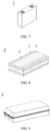
- FIG. 7 shows a rectangular battery 1 as an example.
- the battery may include an outer package.
- the outer package is used for packaging a positive electrode plate, a negative electrode plate, and an electrolyte.
- the outer package may include a housing and a cover plate.
- the housing may include a base plate and side plates connected onto the base plate, and the base plate and the side plates enclose an accommodating cavity.
- the housing has an opening communicating with the accommodating cavity, and the cover plate can cover the opening to close the accommodating cavity.
- the positive electrode plate, the negative electrode plate, and the separator may be made into an electrode assembly through winding or lamination.
- the electrode assembly is packaged in the accommodating cavity.
- the electrolyte may be a liquid electrolyte, and the liquid electrolyte infiltrates into the electrode assembly.
- the outer package of the battery may be a hard shell, for example, a hard plastic shell, an aluminum shell, or a steel shell.
- the outer package of the battery may alternatively be a soft pack, for example, a soft pouch.
- a material of the soft package may be plastic, for example, may include one or more of polypropylene (PP), polybutylene terephthalate (PBT), and polybutylene succinate (PBS).
- PP polypropylene
- PBT polybutylene terephthalate
- PBS polybutylene succinate
- batteries may be assembled into a battery module, and the battery module may include a plurality of batteries. A specific quantity may be adjusted based on application and capacity of the battery module.
- FIG. 8 shows a battery module 2 as an example.
- a plurality of batteries 1 may be sequentially arranged in a length direction of the battery module 2.
- the batteries may alternatively be arranged in any other manner.
- the plurality of batteries 1 may be fastened through fasteners.
- the battery module 2 may further include a shell with an accommodating space, and the plurality of secondary batteries 1 are accommodated in the accommodating space.
- the battery module may be further assembled into a battery pack, and a quantity of battery modules included in the battery pack may be adjusted based on application and capacity of the battery pack.
- FIG. 9 and FIG. 10 show a battery pack 3 as an example.
- the battery pack 3 may include a battery box and a plurality of battery modules 2 arranged in the battery box.
- the battery box includes an upper box body 4 and a lower box body 5.
- the upper box body 4 can cover the lower box body 5 to form an enclosed space for accommodating the battery modules 2.
- the plurality of battery modules 2 may be arranged in the battery box in any manner.
- the electric apparatus includes the foregoing battery, where the battery is configured to supply electric energy.
- the battery may be used as a power source of the electric apparatus, and may also be used as an energy storage unit of the electric apparatus.
- the electric apparatus may be but is not limited to a mobile device (for example, a mobile phone or a notebook computer), an electric vehicle (for example, a battery electric vehicle, a hybrid electric vehicle, a plug-in hybrid electric vehicle, an electric bicycle, an electric scooter, an electric golf vehicle, or an electric truck), an electric train, a ship, a satellite, or an energy storage system.
- FIG. 11 shows an electric apparatus as an example.
- the electric apparatus is a battery electric vehicle, a hybrid electric vehicle, or a plug-in hybrid electric vehicle.
- the electric apparatus may be a mobile phone, a tablet computer, or a notebook computer.
- Such electric apparatus is generally required to be light and thin and may use a battery as its power source.
- the preparation method of the separator 1 includes: preparing the separator using electrospinning, where the spinning solution is a polyethylene solution; keeping the receiving distance at 15-18 cm, and adjusting the receiving roller speed to 200 r/min, the liquid spray speed to 10 mL/h, and the voltage to 23 KV, to obtain the positive electrode end of the separator with a first aperture of 30 nm; and adjusting the receiving roller speed to 150 r/min, the liquid spray speed to 10 mL/h, and the voltage to 23 KV to obtain the negative electrode end of the separator with a second aperture of 20 nm.
- the preparation methods of the separators 2 to 9 are the same as that of the separator 1, with the differences shown in Table 1.
- Table 1 Positive electrode end Negative electrode end Receiving roller speed (r/min) Liquid spray speed (mL/h) Voltage (KV) Aperture of first opening Receiving roller speed (r/min) Liquid spray speed (mL/h) Voltage (KV) Aperture of second opening Separator 1 200 10 23 30nm 150 10 23 20nm Separator 2 250 9 22 50nm 200 10 23 30nm Separator 3 300 8 20 100nm 250 9 22 50nm Separator 4 500 5 19 500nm 350 6 20 200nm Separator 5 600 1 18 1000nm 500 5 19 500nm Separator 6 1000 0.5 18 20 ⁇ m 700 0.5 18 10 ⁇ m Separator 7 1200 0.5 18 500 ⁇ m 1050 0.5 18 300 ⁇ m Separator 8 1600 0.3 18 800 ⁇ m 1200 0.5 18 500 ⁇ m Separator 9 2000 0.3 18 1000 ⁇ m 1600 0.3 18 800 ⁇ m.
- the preparation method of the separator 10 includes: with a polyethylene solution as the spinning solution, using electrospinning to synchronously spray the polyethylene film capillary structure and the separator of the target length, covering the separator with the capillary structure film when the separator is sprayed to about half the target thickness, and continuing to complete the spraying of the remaining thickness of the separator; or using a dual-needle electrospinning device to make a composite separator with a composite capillary structure through intermittent spraying; where the first aperture at the positive electrode end of the separator is 20 ⁇ m, the second aperture at the negative electrode end of the separator is 10 ⁇ m, and the height H 1 of the capillary structure in the separator is 70%H 2 , H 2 being the height of the separator.
- the preparation methods of the separators 11 to 13 are the same as that of the separator 10, with the differences shown in Table 2.
- Table 2 Positive electrode end Negative electrode end Capillary structure Material Aperture of first opening Material Aperture of second opening Length H 1 Separator 10 Polyethylene 20 ⁇ m Polyethylene 10 ⁇ m 70H 2 Separator 11 Polyethylene 20 ⁇ m Polyethylene 10 ⁇ m 80H 2 Separator 12 Polyethylene 20 ⁇ m Polyethylene 10 ⁇ m 90H 2 Separator 13 Polyethylene 20 ⁇ m Polyethylene 10 ⁇ m 100H 2
- the preparation method of the separator 14 includes:
- the preparation methods of the separators 15 and 16 are the same as that of the separator 14, with the differences shown in Table 3.
- Table 3 Sponge-based film Inorganic particle coating Material Aperture of first opening ( ⁇ m) Height H 1 of capillary structure Composition Aperture of second opening ( ⁇ m) Thickness ( ⁇ m) Separator 14 Polyethylene 20 80%H 2 Aluminum trioxide 10 3 Separator 15 Polyethylene 20 80%H 2 Aluminum trioxide 10 5 Separator 16 Polyethylene 20 80%H 2 Aluminum trioxide 10 8
- the preparation method of the separator 17 includes:
- D v 50 is a corresponding particle size when a cumulative volume percentage reaches 50%.
- the D v 50 of the inorganic particles aluminum trioxide can be determined using the laser diffraction particle size analysis method, for example, determined using a laser particle size analyzer (for example, Malvern Master Size 3000) with reference to the standard GB/T 19077-2016.
- a laser particle size analyzer for example, Malvern Master Size 3000
- the preparation methods of the separators 18 and 19 are the same as that of the separator 17, with the differences shown in Table 4.
- Table 4 Sponge-based film First inorganic particle coating Second inorganic particle coating Material Aperture ( ⁇ m) Height H 1 of capillary structure Composition Aperture of first opening ( ⁇ m) Thickness ( ⁇ m) Composition Aperture of second opening ( ⁇ m) Thickness ( ⁇ m) Separator 17 Polyethylene 20 80%H 2 Aluminum trioxide 20 3 Aluminum trioxide 10 5 Separator 18 Polyethylene 20 80%H 2 Aluminum trioxide 20 3 Aluminum trioxide 10 7 Separator 19 Polyethylene 20 80%H 2 Aluminum trioxide 20 3 Aluminum trioxide 10 8
- a polyethylene-based film is used as the separator 20, where the aperture at both the positive electrode end and the negative electrode end of the polyethylene-based film is 20 ⁇ m.
- the preparation method of the separator 21 includes: mixing inorganic particles aluminum trioxide (with D v 50 being 1 ⁇ m) with a binder polyvinylidene fluoride (with the mass ratio of the inorganic particles to the binder polyvinylidene fluoride being 99:1), and applying a resulting inorganic particle slurry to both side surfaces of the polyethylene-based film, followed by drying to form an inorganic particle coating with a thickness of 3 ⁇ m on both side surfaces of the polyethylene-based film, where the aperture of the inorganic particle coating is 20 ⁇ m.
- a binder polyvinylidene fluoride was fully dissolved in N-methylpyrrolidone, and then a conductive agent carbon black and a positive electrode active material Na 4 Fe 3 (PO 4 ) 2 P 2 O 7 were added to produce a uniformly dispersed positive electrode slurry (a mass ratio of the polyvinylidene fluoride, conductive agent carbon black, and positive electrode active material Na 4 Fe 3 (PO 4 ) 2 P 2 O 7 was 10:10:80).
- the positive electrode slurry was evenly applied onto two surfaces of the aluminum foil which was then transferred to a vacuum drying oven and fully dried. The obtained electrode plate was rolled and finally punched to obtain a positive electrode plate.
- a negative electrode active material artificial graphite, a conductive agent carbon black (Super P), a binder styrene-butadiene rubber (SBR), and sodium carboxymethyl cellulose (CMC) were mixed to uniformity at a mass ratio of 96.4:0.7:1.8:1.1 in an appropriate amount of solvent deionized water to obtain a negative electrode slurry.
- the negative electrode slurry was applied on a negative electrode current collector copper foil, followed by processes of drying, cold pressing, slitting, and cutting to obtain a negative electrode plate.
- the separator 1 prepared above was used as the separator.
- Ethylene carbonate (EC) and ethyl methyl carbonate (EMC) were mixed at a mass ratio of30:70 to obtain an organic solvent.
- Fully dried electrolytic salt NaPF 6 was dissolved in the above mixed solvent, with a concentration of the electrolytic salt being 1.0 mol/L. Then, the resulting product was well mixed to obtain an electrolyte.
- the positive electrode plate, the separator, and the negative electrode plate were sequentially stacked so that the separator was located between the positive electrode plate and the negative electrode plate to provide separation. Then, the resulting stack was wound to form an electrode assembly.
- the electrode assembly was placed in the outer package and the prepared electrolyte was injected into the lithium-ion battery that was dried, followed by processes including vacuum packaging, standing, formation, and shaping, to obtain a sodium-ion battery.
- the separators 2 to 19 shown in Tables 1 to 4 were respectively used as the separators of the sodium-ion batteries in Examples 2 to 19.
- the separators 20 and 21 were respectively used as the separators of the sodium-ion batteries in Comparative examples 1 and 2.
- Battery cycle life The number of cycles when the battery capacity retention rate decays to 80%.
- the aperture at the negative electrode end of the separator in the sodium-ion batteries of Examples 1 to 19 is smaller than that at the positive electrode end, while the aperture at the negative electrode end of the separator used in the sodium-ion batteries of Comparative examples 1 and 2 is the same as that at the positive electrode end.
- the data in Table 5 shows that the cycle life of the sodium-ion batteries in Examples 1 to 19 is significantly better than that in Comparative examples 1 and 2. This indicates that compared with the separator in the prior art, the separator of this application with a larger aperture at the negative electrode end than at the positive electrode end can reduce battery capacity loss and improve battery safety performance.
Landscapes
- Chemical & Material Sciences (AREA)
- Chemical Kinetics & Catalysis (AREA)
- Electrochemistry (AREA)
- General Chemical & Material Sciences (AREA)
- Engineering & Computer Science (AREA)
- Materials Engineering (AREA)
- Inorganic Chemistry (AREA)
- Manufacturing & Machinery (AREA)
- Ceramic Engineering (AREA)
- Composite Materials (AREA)
- Cell Separators (AREA)
- Secondary Cells (AREA)
Abstract
Description
- This application relates to the field of secondary batteries, and specifically, to a separator, a battery, and an electric device.
- Secondary batteries have been widely used in various consumer electronic products and electric vehicles due to their prominent advantages such as light weight, no pollution, and no memory effect. However, after multiple cycles, the negative electrode plate undergoes volume swelling, which can easily cause battery capacity loss and safety issues.
- In view of the technical problems described in the background, this application provides a separator, aiming to solve the battery capacity loss and safety issues caused by volume swelling of the negative electrode plate during battery cycling.
- To achieve the above objectives, a first aspect of an embodiment of this application provides a separator, where in a thickness direction of the separator, the separator has a positive electrode end and a negative electrode end, the positive electrode end is provided with a plurality of first openings, the negative electrode end is provided with a plurality of second openings, and an aperture of the first opening is larger than an aperture of the second opening.
- Therefore, use of the separator of this application can solve the battery capacity loss and safety issues caused by volume swelling of the negative electrode plate during the metal battery cycling process.
- In some embodiments of this application, the aperture of the first opening is 20 nm-1000 µm, preferably 50 nm-500 µm.
- In some embodiments of this application, the aperture of the second opening is 20 nm-500 µm, preferably 50 nm-100 µm. Thus, the electrolyte retention effect of the negative electrode end of the separator can be improved while increasing its density, thereby solving the battery capacity loss and safety issues caused by volume swelling of the negative electrode plate during the metal battery cycling process.
- In some embodiments of this application, along a direction from the negative electrode end to the positive electrode end, the apertures of the openings in the separator increase sequentially. Thus, the concentration gradient of metal ion diffusion during the battery charging process can be adjusted, so that metal ions are evenly deposited on the surface of the negative electrode plate, reducing the production of metal dendrites as well as the volume swelling of the negative electrode plate.
- In some embodiments of this application, a capillary structure is provided in the separator along a height direction of the separator, and one end of the capillary structure is flush with a lowermost end of the separator. Thus, when the negative electrode plate undergoes volume swelling and squeezes the separator, the siphoning effect of the capillary can be utilized to siphon the electrolyte from the bottom of the cell into the separator, promptly replenishing the insufficient electrolyte in the height direction of the separator.
- In some embodiments of this application, a length H1 of the capillary structure is ≥70%H2, where H2 is a height of the separator. Thus, the insufficient electrolyte in the height direction of the separator can be promptly replenished.
- In some embodiments of this application, a compression modulus of the separator is 5%-95%. Thus, the battery bulge caused by the volume swelling of the negative electrode plate can be reduced, improving the safety performance of the battery.
- In some embodiments of this application, the separator is a sponge-based film. This can improve the electrolyte retention effect, reducing battery capacity loss.
- In some embodiments of this application, the separator includes a sponge-based film and a coating, the coating is formed on at least one side of the sponge-based film, and the capillary structure is provided in the sponge-based film. This can improve the electrolyte retention effect and strength of the separator, solving the battery capacity loss and safety issues caused by the volume swelling of the negative electrode plate during the metal battery cycling process.
- In some embodiments of this application, the sponge-based film includes at least one of glass fiber, nanofiber, polyethylene, polypropylene, and non-woven fabric. This can improve the electrolyte retention effect, reducing battery capacity loss.
- In some embodiments of this application, the coating is formed on one side of the sponge-based film, the second openings are provided on the coating, and the first openings are provided on an end of the sponge-based film far away from the coating. This can improve the electrolyte retention effect and strength of the separator, solving the battery capacity loss and safety issues caused by the volume swelling of the negative electrode plate during the metal battery cycling process.
- In some embodiments of this application, the coating is formed on both sides of the sponge-based film, the second openings are provided on the coating at the negative electrode end, and the first openings are provided on the coating at the positive electrode end. This can improve the electrolyte retention effect and strength of the separator, solving the battery capacity loss and safety issues caused by the volume swelling of the negative electrode plate during the metal battery cycling process.
- In some embodiments of this application, the separator includes a first separator, a middle separator, and a second separator stacked along a thickness direction of the separator, the first openings are provided on the first separator, and the second openings are provided on the second separator.
- In some embodiments of this application, an aperture of the middle separator is larger than an aperture of the first opening or an aperture of the second opening; and/or a porosity of the middle separator is larger than a porosity of the first separator or a porosity of the second separator. This can improve the electrolyte retention effect of the separator, reducing battery capacity loss.
- In some embodiments of this application, the first separator, the middle separator, and the second separator satisfy at least one of the following conditions:
- the porosity of the first separator is 30%-70%;
- the aperture of the middle separator is 30 nm-1 µm;
- the porosity of the middle separator is 40%-90%; and
- the porosity of the second separator is 30%-70%.
- This can improve the electrolyte retention effect of the separator, reducing battery capacity loss.
- A second aspect of an embodiment of this application provides a battery. The battery includes a positive electrode plate, a negative electrode plate, and a separator, where the separator is provided between the positive electrode plate and the negative electrode plate, the separator includes the separator according to the first aspect of this application, a positive electrode end of the separator is provided close to the positive electrode plate, and a negative electrode end of the separator is provided close to the negative electrode plate.
- Thus, during the charge and discharge cycles, the battery has the advantages of small capacity loss and high safety.
- In some embodiments of this application, the battery is an alkali metal battery, and the alkali metal battery satisfies the following relationship: h2*n2*k =Es*n1*z*(C1*m1/C2/ρ), where Es is an empirical parameter with a value range of 5%-100%; C1 is a total gram capacity of a single positive electrode plate, in mA·h/g; m1 is a unit weight of the positive electrode active material layer of a single positive electrode plate, in g/cm2; n1 is the number of layers of positive electrode plates in a single cell; z is the number of coated surfaces of a single positive electrode plate; C2 is a theoretical gram capacity corresponding to alkali metal of the alkali metal battery, in mA-h/g; ρ is a theoretical density of the alkali metal, in g/cm3; h2 is a thickness of a single separator, in cm; n2 is the number of layers of separators in a single cell; and k is a compression percentage of a single separator. Thus, the battery has a small volume change during the charge and discharge cycle.
- A third aspect of this application provides an electric device including the battery according to the third aspect, where the battery is configured to supply electric energy.
- Additional aspects and advantages of this application will be given in part in the following description, part of which will become apparent from the following description or be learned from the practice of this application.
- Persons of ordinary skill in the art will be clear about various other advantages and benefits by reading the detailed description of the preferred embodiments below. The accompanying drawings are merely intended to illustrate the preferred embodiments and are not intended to limit this application. In addition, in all the accompanying drawings, the same reference signs represent the same components. In the accompanying drawings:
-
FIG. 1 is a schematic structural diagram of a separator according to an embodiment of this application; -
FIG. 2 is a schematic structural diagram of a separator according to another embodiment of this application; -
FIG. 3 is a schematic structural diagram of a separator according to still another embodiment of this application; -
FIG. 4 is a schematic structural diagram of a separator according to still another embodiment of this application; -
FIG. 5 is a schematic structural diagram of a separator according to still another embodiment of this application; -
FIG. 6 is a schematic structural diagram of a separator according to still another embodiment of this application; -
FIG. 7 is a schematic structural diagram of a battery according to an embodiment of this application; -
FIG. 8 is a schematic structural diagram of a battery module according to an embodiment of this application; -
FIG. 9 is a schematic structural diagram of a battery pack according to an embodiment of this application; -
FIG. 10 is an exploded view ofFIG. 9 ; and -
FIG. 11 is a schematic diagram of an embodiment of an electric apparatus using a battery as a power source. -
- 1000: separator; 11: positive electrode end; 110: first opening; 12: negative electrode end; 120: second opening; 13: capillary structure; 14: sponge-based film; 15: coating; 100: first separator; 200: middle separator; 300: second separator;
- 1. secondary battery; 2. battery module; 3. battery pack; 4. upper box body; and 5. lower box body.
- The following describes the embodiments of the technical solutions of this application in detail. The following embodiments are merely intended for a clearer description of the technical solutions of this application and therefore are merely used as examples but do not constitute any limitation on the protection scope of this application.
- Reference to "embodiment" in the specification means that specific features, structures, or characteristics described with reference to the embodiment may be included in at least one embodiment of this application. The word "embodiment" appearing in various positions in the specification does not necessarily refer to the same embodiment or an independent or alternative embodiment that is exclusive of other embodiments. Persons skilled in the art explicitly and implicitly understand that the embodiments described herein may combine with another embodiment.
- For brevity, this specification specifically discloses only some numerical ranges. However, any lower limit may be combined with any upper limit to form a range not expressly recorded; any lower limit may be combined with any other lower limit to form a range not expressly recorded; and any upper limit may be combined with any other upper limit to form a range not expressly recorded. In addition, each individually disclosed point or individual single numerical value may itself be a lower limit or an upper limit which can be combined with any other point or individual numerical value or combined with another lower limit or upper limit to form a range not expressly recorded.
- In the description of the embodiments of this application, the term "and/or" is only an associative relationship for describing associated objects, indicating that three relationships may be present. For example, A and/or B may indicate the following three cases: presence of only A, presence of both A and B, and presence of only B. In addition, a character "/" in this specification generally indicates an "or" relationship between contextually associated objects.
- Unless otherwise defined, all technical and scientific terms used herein shall have the same meanings as commonly understood by persons skilled in the art to which this application relates. The terms used herein are intended to merely describe the specific embodiments rather than to limit this application. The terms "include", "comprise", and "have" and any other variations thereof in the specification, claims and brief description of drawings of this application are intended to cover non-exclusive inclusions.
- A first aspect of an embodiment of this application provides a
separator 1000. Referring toFIGs. 1 and 2 , in a thickness direction of theseparator 1000, theseparator 1000 has apositive electrode end 11 and anegative electrode end 12. Thepositive electrode end 11 is provided with a plurality offirst openings 110, and thenegative electrode end 12 is provided with a plurality ofsecond openings 120. An aperture of thefirst opening 110 is larger than an aperture of thesecond opening 120. - It should be noted that "the positive electrode end of the separator" can be understood as an end of the separator close to the positive electrode after the positive electrode plate, the separator, and the negative electrode plate are stacked and assembled into a cell. Similarly, "the negative electrode end of the separator" can be understood as an end of the separator close to the negative electrode after the positive electrode plate, the separator, and the negative electrode plate are stacked and assembled into a cell. The term "plurality" means two or more.
- The
first openings 110 are provided at thepositive electrode end 11 of theseparator 1000, thesecond openings 120 are provided at thenegative electrode end 120 of theseparator 1000, and the aperture of thefirst opening 110 is larger than the aperture of thesecond opening 120. In one aspect, during the battery cycling, the volume swelling of the negative electrode plate squeezes thenegative electrode end 12 of theseparator 1000, causing thenegative electrode end 12 to be compressed more than thepositive electrode end 11, making the electrolyte between thenegative electrode end 12 of theseparator 1000 and the negative electrode plate prone to dry out. In this application, with the small-aperturesecond openings 120 provided at thenegative electrode end 12 of theseparator 1000, the small-aperturesecond openings 120 provide good electrolyte retention effect, making the electrolyte between theseparator 1000 and the negative electrode plate less likely to dry out, thereby reducing battery capacity loss. In another aspect, thenegative electrode end 12 provided with the small-aperturesecond openings 120 has good compactness, reducing the probability of metal dendrites generated on the surface of the negative electrode plate piercing theseparator 1000 and causing a short circuit, thereby improving battery safety. Moreover, with the larger-aperturefirst openings 110 provided at thepositive electrode end 11 and the smaller-aperturesecond openings 120 provided at thenegative electrode end 12, the concentration gradient of metal ion diffusion can be adjusted during the battery charging process, so that metal ions can be evenly deposited on the surface of the negative electrode plate, thereby reducing the generation of metal dendrites and the volume swelling of the negative electrode plate, and improving battery safety. Therefore, use of theseparator 1000 of this application can solve the battery capacity loss and safety issues caused by volume swelling of the negative electrode plate during the metal battery cycling process. - When the
separator 1000 of this application satisfies the foregoing conditions, the battery capacity loss can be further reduced and the battery safety performance can be further improved if one or more of the following conditions are also satisfied optionally. - In some embodiments, the aperture of the
first opening 110 at thepositive electrode end 11 of theseparator 1000 is 20 nm-1000 µm, for example, 30 nm-1000 µm, 40 nm-1000 µm, 50 nm-1000 µm, 60 nm-1000 µm, 70 nm-1000 µm, 80 nm-1000 µm, 90 nm-1000 µm, 100 nm-1000 µm, 200 nm-1000 µm, 300 nm-1000 µm, 400 nm-1000 µm, 500 nm-1000 µm, 600 nm-1000 µm, 700 nm-1000 µm, 800 nm-1000 µm, 900 nm-1000 µm, 1000 nm-1000 µm, 10 µm-1000 µm, 50 µm-900 µm, 100 µm-800 µm, 150 µm-750 µm, 200 µm-700 µm, 250 µm-650 µm, 300 µm-600 µm, 350 µm-550 µm, or 400 µm-500 µm. If the aperture of thefirst opening 110 is excessively small, the ion conductivity at thepositive electrode end 11 is poor. If the aperture of thefirst opening 110 is excessively large, thepositive electrode end 11 of theseparator 1000 will absorb a large amount of electrolyte. During the charge and discharge process, when the negative electrode plate undergoes volume swelling and squeezes theseparator 1000, the electrolyte adsorbed by thepositive electrode end 11 cannot flow back in time, causing local electrolyte disconnection. This causes uneven deposition on the surface of the negative electrode plate and makes it impossible to block the influence of particles such as powder falling from part of the active material layer of the positive electrode plate from causing local micro short circuits. In some other embodiments, the aperture of thefirst opening 110 at thepositive electrode end 11 is 50 nm-500 µm. - In some embodiments, the aperture of the
second opening 120 at thenegative electrode end 12 of theseparator 1000 is 20 nm-500 µm, for example, 30 nm-500 µm, 40 nm-500 µm, 50 nm-500 µm, 60 nm-500 µm, 70 nm-500 µm, 80 nm-500 µm, 90 nm-500 µm, 100 nm-500 µm, 200 nm-500 µm, 300 nm-500 µm, 400 nm-500 µm, 500 nm-500 µm, 600 nm-500 µm, 700 nm-500 µm, 800 nm-500 µm, 900 nm-500 µm, 1000 nm-500 µm, 10 µm-500 µm, 50 µm-450 µm, 100 µm-400 µm, 150 µm-350 µm, or 200 µm-300 µm. Thus, thesecond openings 120 meeting such aperture can improve the electrolyte retention effect of thenegative electrode end 12, making the electrolyte between theseparator 1000 and the negative electrode plate less likely to dry out, thereby reducing battery capacity loss. Moreover, suchsecond openings 120 can improve the compactness of thenegative electrode end 12, reducing the probability of metal dendrites generated on the surface of the negative electrode plate piercing theseparator 1000 and causing a short circuit, thereby improving battery safety. In some other embodiments, the aperture of thesecond opening 120 at thenegative electrode end 12 is 50 nm-100 µm. - In some embodiments, along a direction from the
negative electrode end 12 to thepositive electrode end 11, the apertures of the openings in theseparator 1000 increase sequentially. Thus, with the openings in theseparator 1000 arranged from thenegative electrode end 12 to thepositive electrode end 11 in ascending order of aperture, the concentration gradient of metal ion diffusion can be further adjusted during the battery charging process, so that metal ions can be evenly deposited on the surface of the negative electrode plate, thereby reducing the generation of metal dendrites and the volume swelling of the negative electrode plate, and improving battery safety. - In some embodiments, to further improve the electrolyte retention effect of the separator, referring to
FIG. 3 , acapillary structure 13 is provided in theseparator 1000 along a height direction of theseparator 1000, and one end of thecapillary structure 13 is flush with a lowermost end of theseparator 1000. Thus, when the negative electrode plate undergoes volume swelling and squeezes theseparator 1000, the siphoning effect of the capillary can be utilized to siphon the electrolyte from the bottom of the cell into theseparator 1000, promptly replenishing the insufficient electrolyte in the height direction of theseparator 1000. - In some embodiments, a length H1 of the
capillary structure 13 is ≥70%H2, where H2 is the height of theseparator 1000, for example, 70%H2, 75%H2, 80%H2, 85%H2, 90%H2, 95%H2, or 100%H2. Thus, the electrolyte from the bottom of the cell can be siphoned to the upper part of theseparator 1000, promptly replenishing the insufficient electrolyte in the upper part of theseparator 1000. - In some embodiments, the
capillary structure 13 can adopt a tree-like structure, for example, adopting a main structure with large channels combined with branch structures with small channels, with the branch structures with small channels communicating with the main structure with large channels. This not only allows the electrolyte from the bottom of the cell to be siphoned to the upper layer of theseparator 1000 through the main structure with large channels, but also allows the electrolyte to be transported to various layers in theseparator 1000 through the branch structures with small channels, thereby promptly replenishing the insufficient electrolyte in theseparator 1000. - In some embodiments, a compression modulus of the
separator 1000 is 5%-95%, for example, 10%-90%, 20%-80%, 30%-70%, 40%-60%, or 40%-50%. Thus, with theseparator 1000 having the compression modulus of this application, when the negative electrode plate undergoes volume swelling, the battery bulge caused by the volume swelling of the negative electrode plate can be effectively alleviated, thereby improving the safety performance of the battery. - According to some examples, the compression modulus of the
separator 1000 is measured using a universal testing machine (MDTC-EQ-M12-01), which specifically includes the following steps. -
Step 1. Select the separator to be tested: Stack multiple layers of separator, ensure that the thickness of the test sample is ≥1 mm, and control the error precision. -
Step 2. Collect the initial thickness: Apply an initial pressure to the separator (try an initial value of ≥0.05 MPa) to obtain the initial thickness of the separator under this constant pressure. -
Step 3. Collect the compression modulus: Continuously apply pressure to the separator until the thickness remains unchanged and the pressure/intensity of pressure shows an exponential increase inflection point. At that time, data collection is considered complete. The slope of the start segment of the strain-stress curve corresponds to the compression modulus of this sample. The compression modulus of different target samples can be obtained in this way. - In some embodiments, the
separator 1000 is a sponge-based film. It should be noted that the "sponge-based film" can be understood as a film with a sponge-like structure. In an example, its material may include at least one of glass fiber, nanofiber, polyethylene, polypropylene, and non-woven fabric. - In some embodiments, to further improve the safety performance of the battery, referring to
FIGs. 4 and5 , theseparator 1000 includes a sponge-basedfilm 14 and acoating 15, thecoating 15 is formed on at least one side of the sponge-basedfilm 14, and thecapillary structure 13 is provided in the sponge-basedfilm 14. In an example, referring toFIG. 4 , thecoating 15 is formed on one side of the sponge-basedfilm 14, thesecond openings 120 are provided on thecoating 15, and thefirst openings 110 are provided on an end of the sponge-basedfilm 11 far away from thecoating 15. Thus, with the sponge-basedfilm 14 including thecapillary structure 13, the electrolyte retention effect of theseparator 1000 can be improved. Moreover, providing thecoating 15 on one side of the sponge-basedfilm 14 as thenegative electrode end 12 of theseparator 1000, with thesecond openings 120 provided in thecoating 15, can significantly improve the puncture resistance and high-temperature resistance of theseparator 1000, thereby enhancing the battery safety performance. - In another example, referring to
FIG. 5 , thecoating 15 is formed on both sides of the sponge-basedfilm 14, thesecond openings 120 are provided on thecoating 15 at thenegative electrode end 12, and thefirst openings 110 are provided on thecoating 15 at thepositive electrode end 11. Thus, with the sponge-basedfilm 14 including thecapillary structure 13, the electrolyte retention effect of theseparator 1000 can be improved. Moreover, with thecoating 15 provided on both sides of the sponge-basedfilm 14, the high-temperature resistance of theseparator 1000 can be significantly improved, thereby enhancing the battery safety performance. - In some embodiments, the
coating 15 may include an inorganic particle coating or a gel electrolyte coating. In an example, the inorganic particles used in the inorganic particle coating may include one or more of boehmite (γ-AlOOH), aluminum oxide (Al2O3), barium sulfate (BaSO4), magnesium oxide (MgO), magnesium hydroxide (Mg(OH)2), silicon dioxide (SiO2), tin dioxide (SnO2), titanium oxide (TiO2), calcium oxide (CaO), zinc oxide (ZnO), zirconium oxide (ZrO2), yttrium oxide (Y2O3), nickel oxide (NiO), cerium oxide (CeO2), zirconium titanate (SrTiO3), barium titanate (BaTiO3), and magnesium fluoride (MgF2). These inorganic particles have a good inhibitory effect on the thermal shrinkage of the separator, thereby improving the high-temperature resistance and puncture resistance of the separator. In an example, the gel electrolyte in the gel electrolyte coating may include polyvinylidene fluoride (PVDF), polyvinylidene fluoride-hexafluoropropylene copolymer [P(VDFHFP)], polyethylene oxide (PEO), polyacrylonitrile (PAN), polymethyl methacrylate (PMMA), and the like. - In some embodiments, a thickness of the inorganic particle coating is 0.5 µm-8 µm, for example, 1 µm-8 µm, 1.5 µm-7.5 µm, 2 µm-7 µm, 2.5 µm-6.5 µm, 3 µm-6 µm, 3.5 µm-5.5 µm, or 4 µm-5 µm. Thus, the high-temperature resistance and puncture resistance of the separator can be improved, enhancing the battery safety performance.
- In some embodiments, a thickness of the gel electrolyte coating is 5 µm-15 µm, for example, 6 µm-15 µm, 7 µm-14 µm, 8 µm-13 µm, 9 µm-12 µm, or 10 µm-11 µm. Thus, the high-temperature resistance and puncture resistance of the separator can be improved, enhancing the battery safety performance.
- In some embodiments, the inorganic particle coating and the gel electrolyte coating may further include a binder. In an example, the binder may be one or more of styrene-butadiene rubber (SBR), water-based acrylic resin (water-based acrylic resin), polyvinylidene fluoride (PVDF), polytetrafluoroethylene (PTFE), ethylene-vinyl acetate copolymer (EVA), polyacrylic acid (PAA), carboxymethyl cellulose (CMC), polyvinyl alcohol (PVA), and polyvinyl butyral (PVB).
- In some embodiments, the inorganic particle coating and the gel electrolyte coating may further include other organic compounds, for example, may include a polymer for improving heat resistance, a dispersant, a wetting agent, a binder of another type, and the like. This application imposes no particular limitation on types of the foregoing other organic compounds, and any commonly known material with good improvement performance can be selected.
- In some embodiments, referring to
FIG. 6 , theseparator 1000 includes afirst separator 100, amiddle separator 200, and asecond separator 300 stacked along a thickness direction of theseparator 1000, thefirst openings 110 are provided on thefirst separator 100, and thesecond openings 120 are provided on thesecond separator 300. In an example, an aperture of themiddle separator 200 is larger than an aperture of thefirst opening 110 or an aperture of thesecond opening 120; and/or a porosity of themiddle separator 200 is larger than a porosity of thefirst separator 100 or thesecond separator 300. Thus, with themiddle separator 200 having a large aperture and/or a large porosity, more electrolyte can be stored. When the negative electrode plate undergoes volume swelling and squeezes the electrolyte between the negative electrode plate and theseparator 1000, the electrolyte stored in themiddle separator 200 can promptly replenish the insufficient electrolyte between the negative electrode plate and theseparator 1000. - In some embodiments, the aperture of the
middle separator 200 is 30 nm-1 µm, for example, 30 nm-1 µm, 40 nm-1 µm, 50 nm-1 µm, 60 nm-1 µm, 70 nm-1 µm, 80 nm-1 µm, 90 nm-1 µm, 100 nm-1 µm, 200 nm-1 µm, 300 nm-1 µm, 400 nm-1 µm, 500 nm-1 µm, 600 nm-1 µm, 700 nm-1 µm, 800 nm-1 µm, or 900 nm-1 µm. Thus, themiddle separator 200 meeting such aperture can store more electrolyte, so that the insufficient electrolyte between the negative electrode plate and theseparator 1000 can be promptly replenished. - In some embodiments, the porosity of the
first separator 100 is 30%-70%, for example, 35%-70%, 40%-70%, 45%-70%, 50%-70%, 55%-70%, 60%-70%, or 65%-70%; the porosity of themiddle separator 200 is 40%-90%, for example, 45%-90%, 50%-90%, 55%-90%, 60%-90%, 65%-90%, 70%-90%, 75%-90%, 80%-90%, or 85%-90%; and the porosity of thesecond separator 300 is 30%-70%, for example, 35%-70%, 40%-70%, 45%-70%, 50%-70%, 55%-70%, 60%-70%, or 65%-70%. Thus, themiddle separator 200 meeting such porosity can store more electrolyte, so that the insufficient electrolyte between the negative electrode plate and theseparator 1000 can be promptly replenished. - According to some examples, the porosities of the
first separator 100, themiddle separator 200, and thesecond separator 300 can be determined using the gas displacement method. Specifically, the porosities can be determined with reference to GB/T 24586-2009 through the following steps: Immerse the separator in ethylene methyl carbonate (EMC) for cleaning, and perform measurement using the gas displacement method. The percentage of the opening volume in the separator to the total volume of the separator is the porosity of the separator. The calculation formula is: porosity = (V-V0)/V×100%, where V0 is the true volume, and V is the apparent volume. - A second aspect of this application provides a battery. The battery includes a positive electrode plate, a negative electrode plate, and a separator. The separator is provided between the positive electrode plate and the negative electrode plate. The separator includes the separator according to the first aspect of this application. A positive electrode end of the separator is provided close to the positive electrode plate, and a negative electrode end of the separator is provided close to the negative electrode plate.
- In some embodiments of this application, the battery is an alkali metal battery, such as a sodium-ion battery or a lithium metal battery, and the alkali metal battery satisfies the following relationship: h2*n2*k =Es*n1*z*(C1*m1/C2/ρ), where Es is an empirical parameter with a value range of 5%-100%; C1 is a total gram capacity of a single positive electrode plate, in mA-h/g; m1 is a unit weight of the positive electrode active material layer of a single positive electrode plate, in g/cm2; n1 is the number of layers of positive electrode plates in a single cell; z is the number of coated surfaces of a single positive electrode plate; C2 is a theoretical gram capacity corresponding to alkali metal of the alkali metal battery, in mA·h/g; ρ is a theoretical density of the alkali metal, in g/cm3; h2 is a thickness of a single separator, in cm; n2 is the number of layers of separators in a single cell; and k is a compression percentage of a single separator. Thus, the battery has a small volume change during the charge and discharge cycle.
- According to some examples, the method for measuring the total gram capacity of a single positive electrode plate includes: disassembling the positive electrode plate, assembling a half-cell, and testing the gram capacity performance at a rate of 0.33C at 25°C, so as to obtain the total gram capacity of a single positive electrode plate. The method for measuring the unit weight of the positive electrode active material layer of a single positive electrode plate includes: punching small discs of the positive electrode plate with a fixed diameter, weighing 10 samples, and deducting the mass of the substrate from the average mass to obtain the unit weight of the positive electrode active material layer of a single positive electrode plate. The compression percentage of the separator is measured using a universal testing machine (MDTC-EQ-M12-01), with the compression percentage of the separator = (initial thickness of the separator - thickness of the compressed separator)/initial thickness of the separator.
- The battery is a battery that can be charged after being discharged, to activate active materials for continuous use.
- Typically, the battery includes a positive electrode plate, a negative electrode plate, a separator, and an electrolyte. In a charge and discharge process of the battery, active ions are intercalated and deintercalated between the positive electrode plate and the negative electrode plate. The separator is disposed between the positive electrode plate and the negative electrode plate to provide separation. The electrolyte conducts ions between the positive electrode plate and the negative electrode plate.
- In some embodiments, the battery may be a lithium-ion battery or a sodium-ion battery.
- In the battery, the positive electrode plate typically includes a positive electrode current collector and a positive electrode active material layer provided on the positive electrode current collector. The positive electrode active material layer includes a positive electrode active material.
- The positive electrode current collector may be a common metal foil sheet or a composite current collector (the composite current collector may be made by providing a metal material on a polymer matrix). In an example, an aluminum foil may be used as the positive electrode current collector.
- A specific type of the positive electrode active material is not limited. An active material known in the art that can be used as the positive electrode of the battery can be used, and those skilled in the art may select an active material based on actual needs.
- For example, when the battery is a lithium-ion battery, in an example, the positive electrode active material may include but is not limited to one or more of lithium transition metal oxide, olivine-structured lithium-containing phosphate, and modified compounds thereof. Examples of the lithium transition metal oxide may include but are not limited to one or more of lithium cobalt oxide, lithium nickel oxide, lithium manganese oxide, lithium nickel cobalt oxide, lithium manganese cobalt oxide, lithium nickel manganese oxide, lithium nickel cobalt manganese oxide, lithium nickel cobalt aluminum oxide, and modified compounds thereof. Examples of the olivine-structured lithium-containing phosphate may include but are not limited to one or more of lithium iron phosphate, a composite material of lithium iron phosphate and carbon, lithium manganese phosphate, a composite material of lithium manganese phosphate and carbon, lithium manganese iron phosphate, a composite material of lithium manganese iron phosphate and carbon, and modified compounds thereof. These materials are all commercially available.
- For example, when the battery is a sodium-ion battery, in an example, the positive electrode active material may include but is not limited to at least one of layered transition metal oxide, polyanion compound, and Prussian blue analog.
- Examples of the layered transition metal oxide may include, for example,
- Na1-xCuhFekMniM1 mO2-y, where M1 is one or more of Li, Be, B, Mg, Al, K, Ca, Ti, Co, Ni, Zn, Ga, Sr, Y, Nb, Mo, In, Sn, and Ba, 0<x≤0.33, 0<h≤0.24, 0≤k≤0.32, 0<1≤0.68, 0≤m<0.1, h+k+l+m=1, and 0≤y<0.2;
- Na0.67Mn0.7NizM2 0.3-zO2, where M2 is one or more of Li, Mg, Al, Ca, Ti, Fe, Cu, Zn, and Ba, and 0<z≤0.1; and
- NaaLibNicMnaFeeO2, where 0.67<a≤1, 0<b<0.2, 0<c<0.3, 0.67<d+e<0.8, and b+c+d+e=1.
- Examples of the polyanion compound may include, for example,
- A1 fM3 g(PO4)iOjX1 3-j, where A is one or more of H, Li, Na, K, and NH4, M3 is one or more of Ti, Cr, Mn, Fe, Co, Ni, V, Cu, and Zn, X1 is one or more of F, Cl, and Br, 0<f≤4, 0<g≤2, 1≤i≤3, and 0≤j≤2;
- NanM4PO4X2, where M4 is one or more of Mn, Fe, Co, Ni, Cu, and Zn, X2 is one or more of F, Cl, and Br, and 0<n≤2;
- NapM5 q(SO4)3, where M5 is one or more of Mn, Fe, Co, Ni, Cu, and Zn, 0<p≤2, and 0<q≤2; and
- NasMntFe3-t(PO4)2(P2O7), where 0<s≤4, and 0≤t≤3, for example, t is 0, 1, 1.5, 2, or 3.
- Examples of the Prussian blue analog may include, for example,
AuM6 v[M7(CN)6]w·xH2O, where A is one or more of H+, NH4+, alkali metal cation, and alkaline-earth metal cation, M6 and M7 are each independently one or more of transition metal cations, 0<u≤2, 0<v≤ 1, 0<w≤1, and 0<x<6. For example, A is one or more of H+, Li+, Na+, K+, NH4 +, Rb+, Cs+, Fr+, Be2+, Mg2+, Ca2+, Sr2+, Ba2+, and Ra2+, and M6 and M7 are each independently a cation of one or more transition metal elements selected from Ti, V, Cr, Mn, Fe, Co, Ni, Cu, Zn, Sn, and W. - The modified compounds of the foregoing materials may be obtained through doping modification and/or surface coating modification to the materials.
- The positive electrode active material layer usually further optionally includes a binder, a conductive agent, and other optional adjuvants.
- In an example, the conductive agent may be one or more of superconducting carbon, acetylene black, carbon black, Ketjen black, carbon dots, carbon nanotubes, Super P (SP), graphene, and carbon nanofibers.
- In an example, the binder may be one or more of styrene-butadiene rubber (SBR), water-based acrylic resin (water-based acrylic resin), polyvinylidene fluoride (PVDF), polytetrafluoroethylene (PTFE), ethylene-vinyl acetate copolymer (EVA), polyacrylic acid (PAA), carboxymethyl cellulose (CMC), polyvinyl alcohol (PVA), and polyvinyl butyral (PVB).
- In the battery, the negative electrode plate typically includes a negative electrode current collector and a negative electrode active material layer provided on the negative electrode current collector. The negative electrode active material layer includes a negative electrode active material.
- The negative electrode current collector may be a common metal foil sheet or a composite current collector (for example, the composite current collector may be made by providing a metal material on a polymer matrix). In an example, a copper foil may be used as the negative electrode current collector.
- A specific type of the negative electrode active material is not limited. An active material known in the art that can be used as the negative electrode of the battery can be used, and those skilled in the art may select an active material based on actual needs. In an example, the negative electrode active material may include but is not limited to one or more of artificial graphite, natural graphite, hard carbon, soft carbon, silicon-based material, and tin-based material. The silicon-based material may include one or more of elemental silicon, silicon-oxygen compound (for example, silicon monoxide), silicon-carbon composite, silicon-nitrogen composite, and silicon alloy. The tin-based material may include one or more of elemental tin, tin-oxygen compound, and tin alloy. These materials are all commercially available.
- In some embodiments, the negative electrode active material may include a silicon-based material to further increase the energy density of the battery.
- The negative electrode active material layer usually further optionally includes a binder, a conductive agent, and other optional adjuvants.
- In an example, the conductive agent may be one or more of superconducting carbon, acetylene black, carbon black, Ketjen black, carbon dots, carbon nanotubes, graphene, and carbon nanofibers.
- In an example, the binder may be one or more of styrene-butadiene rubber (SBR), water-based acrylic resin (water-based acrylic resin), polyvinylidene fluoride (PVDF), polytetrafluoroethylene (PTFE), ethylene-vinyl acetate copolymer (EVA), polyvinyl alcohol (PVA), and polyvinyl butyral (PVB).
- In an example, the other optional adjuvants may be, for example, a thickening and dispersing agent (such as sodium carboxymethyl cellulose CMC-Na) and a PTC thermistor material.
- The battery may include an electrolyte, and the electrolyte conducts ions between the positive electrode and the negative electrode. The electrolyte may include an electrolytic salt and a solvent.
- When the battery is a lithium-ion battery, in an example, the electrolytic salt may include one or more selected from a group consisting of lithium hexafluorophosphate (LiPF6), lithium tetrafluoroborate (LiBF4), lithium perchlorate (LiClO4), lithium hexafluoroarsenate (LiAsF6), lithium bistrifluoromethanesulfonimide (LiFSI), lithium bistrifluoromethanesulfonimide (LiTFSI), lithium trifluoromethanesulfonate (LiTFS), lithium difluoro(oxalato)borate (LiDFOB), lithium dioxalate borate (LiBOB), lithium difluorophosphate (LiPO2F2), lithium difluorodioxalate phosphate (LiDFOP), and lithium tetrafluoro oxalato phosphate (LiTFOP).
- When the battery is a sodium-ion battery, in an example, the electrolyte sodium salt includes at least one of sodium hexafluorophosphate, sodium difluoro(oxalato)borate, sodium tetrafluoroborate, sodium bis(oxalato)borate, sodium perchlorate, sodium hexafluoroarsenate, sodium bis(fluorosulfonyl)imide, sodium trifluoromethanesulfonate, and sodium bis(trifluoromethanesulfonyl)imide.
- In an example, the solvent may include one or more selected from a group consisting of ethylene carbonate (EC), propylene carbonate (PC), ethyl methyl carbonate (EMC), diethyl carbonate (DEC), dimethyl carbonate (DMC), dipropyl carbonate (DPC), methyl propyl carbonate (MPC), ethyl propyl carbonate (EPC), butylene carbonate (BC), fluoroethylene carbonate (FEC), methyl formate (MF), methyl acetate (MA), ethyl acetate (EA), propyl acetate (PA), methyl propionate (MP), ethyl propionate (EP), propyl propionate (PP), methyl butyrate (MB), ethyl butyrate (EB), 1,4-gamma-butyrolactone (GBL), sulfolane (SF), methyl sulfonyl methane (MSM), ethyl methanesulfonate (EMS), and diethyl sulfone (ESE).
- In some embodiments, the electrolyte further includes an additive. For example, the additive may include a negative electrode film-forming additive, or may include a positive electrode film-forming additive, or may include an additive capable of improving some performance of the battery, for example, an additive for improving overcharge resistance performance of the battery, an additive for improving high-temperature performance of the battery, or an additive for improving low-temperature performance of the battery.
- The embodiments of this application do not impose any special limitations on a shape of the battery, and the battery may be cylindrical, rectangular, or of any other shapes.
FIG. 7 shows arectangular battery 1 as an example. - In some embodiments, the battery may include an outer package. The outer package is used for packaging a positive electrode plate, a negative electrode plate, and an electrolyte.
- In some embodiments, the outer package may include a housing and a cover plate. The housing may include a base plate and side plates connected onto the base plate, and the base plate and the side plates enclose an accommodating cavity. The housing has an opening communicating with the accommodating cavity, and the cover plate can cover the opening to close the accommodating cavity.
- The positive electrode plate, the negative electrode plate, and the separator may be made into an electrode assembly through winding or lamination. The electrode assembly is packaged in the accommodating cavity. The electrolyte may be a liquid electrolyte, and the liquid electrolyte infiltrates into the electrode assembly. There may be one or more electrode assemblies in the battery, and the quantity may be adjusted as required.
- In some embodiments, the outer package of the battery may be a hard shell, for example, a hard plastic shell, an aluminum shell, or a steel shell.
- The outer package of the battery may alternatively be a soft pack, for example, a soft pouch. A material of the soft package may be plastic, for example, may include one or more of polypropylene (PP), polybutylene terephthalate (PBT), and polybutylene succinate (PBS).
- In some embodiments, batteries may be assembled into a battery module, and the battery module may include a plurality of batteries. A specific quantity may be adjusted based on application and capacity of the battery module.
-
FIG. 8 shows abattery module 2 as an example. Referring toFIG. 8 , in thebattery module 2, a plurality ofbatteries 1 may be sequentially arranged in a length direction of thebattery module 2. Certainly, the batteries may alternatively be arranged in any other manner. Further, the plurality ofbatteries 1 may be fastened through fasteners. - The
battery module 2 may further include a shell with an accommodating space, and the plurality ofsecondary batteries 1 are accommodated in the accommodating space. In some embodiments, the battery module may be further assembled into a battery pack, and a quantity of battery modules included in the battery pack may be adjusted based on application and capacity of the battery pack. -
FIG. 9 andFIG. 10 show abattery pack 3 as an example. Referring toFIG. 9 andFIG. 10 , thebattery pack 3 may include a battery box and a plurality ofbattery modules 2 arranged in the battery box. The battery box includes anupper box body 4 and alower box body 5. Theupper box body 4 can cover thelower box body 5 to form an enclosed space for accommodating thebattery modules 2. The plurality ofbattery modules 2 may be arranged in the battery box in any manner. - This application further provides an electric apparatus. The electric apparatus includes the foregoing battery, where the battery is configured to supply electric energy. Specifically, the battery may be used as a power source of the electric apparatus, and may also be used as an energy storage unit of the electric apparatus. The electric apparatus may be but is not limited to a mobile device (for example, a mobile phone or a notebook computer), an electric vehicle (for example, a battery electric vehicle, a hybrid electric vehicle, a plug-in hybrid electric vehicle, an electric bicycle, an electric scooter, an electric golf vehicle, or an electric truck), an electric train, a ship, a satellite, or an energy storage system.
-
FIG. 11 shows an electric apparatus as an example. The electric apparatus is a battery electric vehicle, a hybrid electric vehicle, or a plug-in hybrid electric vehicle. - In another example, the electric apparatus may be a mobile phone, a tablet computer, or a notebook computer. Such electric apparatus is generally required to be light and thin and may use a battery as its power source.
- To describe the technical problems solved by the embodiments of this application, technical solutions, and beneficial effects more clearly, the following further provides descriptions in detail with reference to the embodiments and accompanying drawings. Apparently, the described embodiments are only some but not all of the embodiments of this application. The following description of at least one example embodiment is merely illustrative and definitely is not construed as any limitation on this application or on use of this application. All other embodiments obtained by persons of ordinary skill in the art based on the embodiments of this application without creative efforts shall fall within the protection scope of this application.
- I. The preparation method of the
separator 1 includes:
preparing the separator using electrospinning, where the spinning solution is a polyethylene solution; keeping the receiving distance at 15-18 cm, and adjusting the receiving roller speed to 200 r/min, the liquid spray speed to 10 mL/h, and the voltage to 23 KV, to obtain the positive electrode end of the separator with a first aperture of 30 nm; and adjusting the receiving roller speed to 150 r/min, the liquid spray speed to 10 mL/h, and the voltage to 23 KV to obtain the negative electrode end of the separator with a second aperture of 20 nm. - The preparation methods of the
separators 2 to 9 are the same as that of theseparator 1, with the differences shown in Table 1.Table 1 Positive electrode end Negative electrode end Receiving roller speed (r/min) Liquid spray speed (mL/h) Voltage (KV) Aperture of first opening Receiving roller speed (r/min) Liquid spray speed (mL/h) Voltage (KV) Aperture of second opening Separator 1 200 10 23 30nm 150 10 23 20nm Separator 2 250 9 22 50nm 200 10 23 30nm Separator 3 300 8 20 100nm 250 9 22 50nm Separator 4 500 5 19 500nm 350 6 20 200nm Separator 5 600 1 18 1000nm 500 5 19 500nm Separator 6 1000 0.5 18 20µm 700 0.5 18 10µm Separator 7 1200 0.5 18 500µm 1050 0.5 18 300µm Separator 8 1600 0.3 18 800µm 1200 0.5 18 500µm Separator 9 2000 0.3 18 1000µm 1600 0.3 18 800µm - II. The preparation method of the separator 10 includes:
with a polyethylene solution as the spinning solution, using electrospinning to synchronously spray the polyethylene film capillary structure and the separator of the target length, covering the separator with the capillary structure film when the separator is sprayed to about half the target thickness, and continuing to complete the spraying of the remaining thickness of the separator; or using a dual-needle electrospinning device to make a composite separator with a composite capillary structure through intermittent spraying; where the first aperture at the positive electrode end of the separator is 20 µm, the second aperture at the negative electrode end of the separator is 10 µm, and the height H1 of the capillary structure in the separator is 70%H2, H2 being the height of the separator. - The preparation methods of the
separators 11 to 13 are the same as that of the separator 10, with the differences shown in Table 2.Table 2 Positive electrode end Negative electrode end Capillary structure Material Aperture of first opening Material Aperture of second opening Length H1 Separator 10 Polyethylene 20µm Polyethylene 10µm 70H2 Separator 11 Polyethylene 20µm Polyethylene 10µm 80H2 Separator 12 Polyethylene 20µm Polyethylene 10µm 90H2 Separator 13 Polyethylene 20µm Polyethylene 10µm 100H2 - III. The preparation method of the
separator 14 includes: - (1) preparing a sponge-based film having a capillary structure: with a polyethylene solution as the spinning solution, using electrospinning to synchronously spray the polyethylene film capillary structure and the separator of the target length, covering the separator with the capillary structure film when the separator is sprayed to about half the target thickness, and continuing to complete the spraying of the remaining thickness of the separator to obtain a sponge-based film having a capillary structure; or using a dual-needle electrospinning device to make a sponge-based film having a composite capillary structure through intermittent spraying; where the aperture of the sponge-based film is 20 µm, and the height H1 of the capillary structure in the separator is 80%H2, H2 being the height of the separator; and
- (2) mixing inorganic particles of aluminum trioxide (with Dv50 of 1.5 µm) with a binder polyvinylidene fluoride (with the mass ratio of the inorganic particles to the binder polyvinylidene fluoride being 99: 1), and applying a resulting inorganic particle slurry to one side surface of the sponge-based film, followed by drying to form an inorganic particle coating on one side surface of the sponge-based film, where the aperture of the inorganic particle coating is 10 µm, and the thickness is 3 µm.
- The preparation methods of the
separators 15 and 16 are the same as that of theseparator 14, with the differences shown in Table 3.Table 3 Sponge-based film Inorganic particle coating Material Aperture of first opening (µm) Height H1 of capillary structure Composition Aperture of second opening (µm) Thickness (µm) Separator 14Polyethylene 20 80%H2 Aluminum trioxide 10 3 Separator 15Polyethylene 20 80%H2 Aluminum trioxide 10 5 Separator 16 Polyethylene 20 80%H2 Aluminum trioxide 10 8 - IV. The preparation method of the separator 17 includes:
- (1) preparing a sponge-based film having a capillary structure: with a polyethylene solution as the spinning solution, using electrospinning to synchronously spray the polyethylene film capillary structure and the separator of the target length, covering the separator with the capillary structure film when the separator is sprayed to about half the target thickness, and continuing to complete the spraying of the remaining thickness of the separator to obtain a sponge-based film having a capillary structure; or using a dual-needle electrospinning device to make a sponge-based film having a composite capillary structure through intermittent spraying; where the aperture of the sponge-based film is 20 µm, and the height H1 of the capillary structure in the separator is 80%H2, H2 being the height of the separator; and
- (2) mixing inorganic particles aluminum trioxide (with Dv50 being 1.0 µm) with a binder polyvinylidene fluoride (with the mass ratio of the inorganic particles to the binder polyvinylidene fluoride being 99: 1), and applying a resulting inorganic particle slurry to one side surface of the sponge-based film, followed by drying to form a first inorganic particle coating as the positive electrode end of the separator, where the aperture of the first inorganic particle coating at the positive electrode end is 20 µm, and the thickness is 3 µm; and mixing inorganic particles aluminum trioxide (with Dv50 being 1.5 µm) with a binder polyvinylidene fluoride (with the mass ratio of the inorganic particles to the binder polyvinylidene fluoride being 99:1), and applying a resulting inorganic particle slurry on the other side surface of the sponge-based film, followed by drying to form a second inorganic particle coating as the negative electrode end of the separator, where the aperture of the second inorganic particle coating at the negative electrode end is 10 µm, and the thickness is 5 µm.
- In this application, Dv50 is a corresponding particle size when a cumulative volume percentage reaches 50%. In this application, the Dv50 of the inorganic particles aluminum trioxide can be determined using the laser diffraction particle size analysis method, for example, determined using a laser particle size analyzer (for example, Malvern Master Size 3000) with reference to the standard GB/T 19077-2016.
- The preparation methods of the separators 18 and 19 are the same as that of the separator 17, with the differences shown in Table 4.
Table 4 Sponge-based film First inorganic particle coating Second inorganic particle coating Material Aperture (µm) Height H1 of capillary structure Composition Aperture of first opening (µm) Thickness (µm) Composition Aperture of second opening (µm) Thickness (µm) Separator 17 Polyethylene 20 80%H2 Aluminum trioxide 20 3 Aluminum trioxide 10 5 Separator 18 Polyethylene 20 80%H2 Aluminum trioxide 20 3 Aluminum trioxide 10 7 Separator 19 Polyethylene 20 80%H2 Aluminum trioxide 20 3 Aluminum trioxide 10 8 - A polyethylene-based film is used as the separator 20, where the aperture at both the positive electrode end and the negative electrode end of the polyethylene-based film is 20 µm.
- The preparation method of the separator 21 includes: mixing inorganic particles aluminum trioxide (with Dv50 being 1 µm) with a binder polyvinylidene fluoride (with the mass ratio of the inorganic particles to the binder polyvinylidene fluoride being 99:1), and applying a resulting inorganic particle slurry to both side surfaces of the polyethylene-based film, followed by drying to form an inorganic particle coating with a thickness of 3 µm on both side surfaces of the polyethylene-based film, where the aperture of the inorganic particle coating is 20 µm.
- A binder polyvinylidene fluoride was fully dissolved in N-methylpyrrolidone, and then a conductive agent carbon black and a positive electrode active material Na4Fe3(PO4)2P2O7 were added to produce a uniformly dispersed positive electrode slurry (a mass ratio of the polyvinylidene fluoride, conductive agent carbon black, and positive electrode active material Na4Fe3(PO4)2P2O7 was 10:10:80). The positive electrode slurry was evenly applied onto two surfaces of the aluminum foil which was then transferred to a vacuum drying oven and fully dried. The obtained electrode plate was rolled and finally punched to obtain a positive electrode plate.
- A negative electrode active material artificial graphite, a conductive agent carbon black (Super P), a binder styrene-butadiene rubber (SBR), and sodium carboxymethyl cellulose (CMC) were mixed to uniformity at a mass ratio of 96.4:0.7:1.8:1.1 in an appropriate amount of solvent deionized water to obtain a negative electrode slurry. The negative electrode slurry was applied on a negative electrode current collector copper foil, followed by processes of drying, cold pressing, slitting, and cutting to obtain a negative electrode plate.
- The
separator 1 prepared above was used as the separator. - Ethylene carbonate (EC) and ethyl methyl carbonate (EMC) were mixed at a mass ratio of30:70 to obtain an organic solvent. Fully dried electrolytic salt NaPF6 was dissolved in the above mixed solvent, with a concentration of the electrolytic salt being 1.0 mol/L. Then, the resulting product was well mixed to obtain an electrolyte.
- The positive electrode plate, the separator, and the negative electrode plate were sequentially stacked so that the separator was located between the positive electrode plate and the negative electrode plate to provide separation. Then, the resulting stack was wound to form an electrode assembly. The electrode assembly was placed in the outer package and the prepared electrolyte was injected into the lithium-ion battery that was dried, followed by processes including vacuum packaging, standing, formation, and shaping, to obtain a sodium-ion battery.
- The
separators 2 to 19 shown in Tables 1 to 4 were respectively used as the separators of the sodium-ion batteries in Examples 2 to 19. The separators 20 and 21 were respectively used as the separators of the sodium-ion batteries in Comparative examples 1 and 2. - Battery cycle life: The number of cycles when the battery capacity retention rate decays to 80%. Taking the battery of Example 1 as an example, the battery capacity retention rate test process was as follows: The battery was charged at 0.33C to a cut-off voltage of 4.35 V, constant-voltage charged at the cut-off voltage of 4.35 V to a current of 0.05C, and discharged at 0.33C to a cut-off voltage of 2.8 V, and the discharge capacity of the first cycle was recorded. Then n charge and discharge cycles were performed, and the discharge capacity of the n-th cycle was recorded. Cycling capacity retention rate = (discharge capacity of the n-th cycle/discharge capacity of the first cycle) × 100%. Five parallel samples were tested, the worst and best data were removed, and the average value of the remaining three samples was used, accurate to the tenth place (rounding principle), to obtain the battery cycle life.
- The performance test results of the sodium-ion batteries in Examples 1 to 19 and Comparative examples 1 and 2 are shown in Table 5.
Table 5 Battery cycle life (capacity retention rate 80%) (cycle) Example 1 640 Example 2 830 Example 3 1350 Example 4 1550 Example 5 1620 Example 6 1770 Example 7 950 Example 8 710 Example 9 580 Example 10 2140 Example 11 2290 Example 12 2310 Example 13 2360 Example 14 2320 Example 15 2360 Example 16 2390 Example 17 2450 Example 18 2480 Example 19 2490 Comparative example 1 300 Comparative example 2 20 - The aperture at the negative electrode end of the separator in the sodium-ion batteries of Examples 1 to 19 is smaller than that at the positive electrode end, while the aperture at the negative electrode end of the separator used in the sodium-ion batteries of Comparative examples 1 and 2 is the same as that at the positive electrode end. The data in Table 5 shows that the cycle life of the sodium-ion batteries in Examples 1 to 19 is significantly better than that in Comparative examples 1 and 2. This indicates that compared with the separator in the prior art, the separator of this application with a larger aperture at the negative electrode end than at the positive electrode end can reduce battery capacity loss and improve battery safety performance.
- In conclusion, it should be noted that the above embodiments are merely intended for describing the technical solutions of this application but not for limiting this application. Although this application is described in detail with reference to the foregoing embodiments, persons of ordinary skill in the art should understand that they may still make modifications to the technical solutions described in the foregoing embodiments or make equivalent replacements to some or all technical features thereof without departing from the scope of the technical solutions of the embodiments of this application. They should all be covered in the scope of the claims and specification of this application. In particular, as long as there is no structural conflict, the various technical features mentioned in the implementations can be combined in any manners. This application is not limited to the specific embodiments disclosed in this specification but includes all technical solutions falling within the scope of the claims.
Claims (18)
- A separator, wherein in a thickness direction of the separator, the separator has a positive electrode end and a negative electrode end, the positive electrode end is provided with a plurality of first openings, the negative electrode end is provided with a plurality of second openings, and an aperture of the first opening is larger than an aperture of the second opening.
- The separator according to claim 1, wherein the aperture of the first opening is 20 nm-1000 µm, preferably 50 nm-500 µm.
- The separator according to claim 1 or 2, wherein the aperture of the second opening is 20 nm-500 µm, preferably 50 nm-100 µm.
- The separator according to any of claims 1 to 3, wherein along a direction from the negative electrode end to the positive electrode end, the apertures of the openings in the separator increase sequentially.
- The separator according to any of claims 1 to 4, wherein a capillary structure is provided in the separator along a height direction of the separator, and one end of the capillary structure is flush with a lowermost end of the separator.
- The separator according to claim 5, wherein a length H1 of the capillary structure is ≥70%H2, and H2 is a height of the separator.
- The separator according to any of claims 1 to 5, wherein a compression modulus of the separator is 5%-95%.
- The separator according to any of claims 1 to 7, wherein the separator is a sponge-based film.
- The separator according to any of claims 1 to 8, wherein the separator comprises a sponge-based film and a coating, the coating is formed on at least one side of the sponge-based film, and the capillary structure is provided in the sponge-based film.
- The separator according to claim 8 or 9, wherein the sponge-based film comprises at least one of glass fiber, nanofiber, polyethylene, polypropylene, and non-woven fabric.
- The separator according to claim 9 or 10, wherein the coating is formed on one side of the sponge-based film, the second openings are provided on the coating, and the first openings are provided on an end of the sponge-based film far away from the coating.
- The separator according to any one of claims 9 to 11, wherein the coating is formed on both sides of the sponge-based film, the second openings are provided on the coating at the negative electrode end, and the first openings are provided on the coating at the positive electrode end.
- The separator according to any one of claims 1 to 12, wherein the separator comprises a first separator, a middle separator, and a second separator stacked along a thickness direction of the separator, the first openings are provided on the first separator, and the second openings are provided on the second separator.
- The separator according to any one of claims 1 to 13, wherein an aperture of the middle separator is larger than the aperture of the first opening or the aperture of the second opening; and/or
a porosity of the middle separator is larger than a porosity of the first separator or the second separator. - The separator according to any one of claims 1 to 14, wherein the first separator, the middle separator, and the second separator satisfy at least one of the following conditions:the porosity of the first separator is 30%-70%;the aperture of the middle separator is 30 nm-1 µm;the porosity of the middle separator is 40%-90%; andthe porosity of the second separator is 30%-70%.
- A battery, wherein the battery comprises a positive electrode plate, a negative electrode plate, and the separator, the separator is provided between the positive electrode plate and the negative electrode plate, the separator comprises the separator according to any one of claims 1 to 15, the positive electrode end of the separator is provided close to the positive electrode plate, and the negative electrode end of the separator is provided close to the negative electrode plate.
- The battery according to claim 16, wherein the battery is an alkali metal battery, and the alkali metal battery satisfies the following relationship:
 wherein Es is an empirical parameter with a value range of 5%-100%;C1 is a total gram capacity of a single positive electrode plate, in mA-h/g;m1 is a unit weight of the positive electrode active material layer of a single positive electrode plate, in g/cm2;n1 is the number of layers of positive electrode plates in a single cell;z is the number of coated surfaces of a single positive electrode plate;C2 is a theoretical gram capacity corresponding to alkali metal of the alkali metal battery, in mA·h/g;ρ is a theoretical density of the alkali metal, in g/cm3;h2 is a thickness of a single separator, in cm;n2 is the number of layers of separators in a single cell; andk is a compression percentage of a single separator.
 - An electric apparatus, comprising the battery according to claim 16 or 17, wherein the battery is configured to provide electric energy.
Applications Claiming Priority (2)
| Application Number | Priority Date | Filing Date | Title |
|---|---|---|---|
| CN202211658946.8A CN118249045A (en) | 2022-12-22 | 2022-12-22 | Isolation films, batteries and electrical equipment |
| PCT/CN2023/116819 WO2024131140A1 (en) | 2022-12-22 | 2023-09-04 | Separator, battery and electrical device |
Publications (2)
| Publication Number | Publication Date |
|---|---|
| EP4564578A1 true EP4564578A1 (en) | 2025-06-04 |
| EP4564578A4 EP4564578A4 (en) | 2025-12-31 |
Family
ID=91556075
Family Applications (1)
| Application Number | Title | Priority Date | Filing Date |
|---|---|---|---|
| EP23905318.4A Pending EP4564578A4 (en) | 2022-12-22 | 2023-09-04 | SEPARATOR, BATTERY AND ELECTRICAL DEVICE |
Country Status (4)
| Country | Link |
|---|---|
| US (1) | US20250226531A1 (en) |
| EP (1) | EP4564578A4 (en) |
| CN (1) | CN118249045A (en) |
| WO (1) | WO2024131140A1 (en) |
Families Citing this family (1)
| Publication number | Priority date | Publication date | Assignee | Title |
|---|---|---|---|---|
| CN121507059A (en) * | 2024-08-08 | 2026-02-10 | 宁德时代新能源科技股份有限公司 | Sodium secondary batteries and electrical devices |
Family Cites Families (11)
| Publication number | Priority date | Publication date | Assignee | Title |
|---|---|---|---|---|
| KR100573358B1 (en) * | 2002-09-17 | 2006-04-24 | 가부시키가이샤 도모에가와 세이시쇼 | Separators for lithium ion secondary batteries and lithium ion secondary batteries including the same |
| JP2014102877A (en) * | 2011-03-10 | 2014-06-05 | Panasonic Corp | Nonaqueous secondary battery |
| CN104362276B (en) * | 2014-10-27 | 2018-04-17 | 乐凯胶片股份有限公司 | A kind of polyethene microporous membrane, preparation method and lithium ion battery |
| CN206076346U (en) * | 2016-09-18 | 2017-04-05 | 苏州市星辰新材料有限公司 | A kind of composite multi-layer lithium battery diaphragm |
| CN108258299B (en) * | 2018-01-10 | 2020-04-17 | 深圳市正翔电池能源有限公司 | Lithium ion power battery |
| CN111211279A (en) * | 2018-11-22 | 2020-05-29 | 宁德新能源科技有限公司 | Isolating membrane and lithium ion battery |
| KR102761527B1 (en) * | 2019-09-19 | 2025-02-03 | 주식회사 엘지에너지솔루션 | Separator having porosity deviation with thickness direction and manufacturing method thereof |
| CN113782915A (en) * | 2021-08-27 | 2021-12-10 | 合肥国轩高科动力能源有限公司 | Diaphragm and preparation method and application thereof |
| CN114614200B (en) * | 2022-03-31 | 2023-12-19 | 宁德新能源科技有限公司 | Electrochemical device and electric equipment |
| CN114843708B (en) * | 2022-07-04 | 2022-10-11 | 中材锂膜(宁乡)有限公司 | Porous diaphragm, preparation method thereof and electrochemical device |
| KR20250036936A (en) * | 2023-02-27 | 2025-03-14 | 컨템포러리 엠퍼렉스 테크놀로지 (홍콩) 리미티드 | Electrode assemblies, battery cells, batteries and electrical devices |
-
2022
- 2022-12-22 CN CN202211658946.8A patent/CN118249045A/en active Pending
-
2023
- 2023-09-04 EP EP23905318.4A patent/EP4564578A4/en active Pending
- 2023-09-04 WO PCT/CN2023/116819 patent/WO2024131140A1/en not_active Ceased
-
2025
- 2025-03-24 US US19/088,676 patent/US20250226531A1/en active Pending
Also Published As
| Publication number | Publication date |
|---|---|
| CN118249045A (en) | 2024-06-25 |
| EP4564578A4 (en) | 2025-12-31 |
| US20250226531A1 (en) | 2025-07-10 |
| WO2024131140A1 (en) | 2024-06-27 |
Similar Documents
| Publication | Publication Date | Title |
|---|---|---|
| US11631852B2 (en) | Secondary battery, preparation method thereof, and battery module, battery pack, and apparatus associated therewith | |
| CN114730910B (en) | Secondary battery, method of manufacturing the same, and battery module, battery pack, and device including the same | |
| KR102502618B1 (en) | Secondary battery, battery module including secondary battery, battery pack and device | |
| US20240313202A1 (en) | Secondary battery, process for preparing the same and apparatus containing the secondary battery | |
| US11646416B2 (en) | Secondary battery, process for preparing the same and apparatus containing the secondary battery | |
| KR101543939B1 (en) | Nonaqueous electrolytic-solution rechargeable battery | |
| KR102909741B1 (en) | Method for charging and discharging secondary battery | |
| US20200212439A1 (en) | Negative electrode active material, negative electrode plate and battery | |
| KR102864154B1 (en) | Lithium secondary battery | |
| US20240145712A1 (en) | Carbon material, preparation method therefor and use thereof, negative electrode plate, secondary battery and power consuming device | |
| EP4020627B1 (en) | Device for pre-lithiation of negative electrode and method for pre-lithiation of negative electrode | |
| US20250226531A1 (en) | Separator, battery, and electric device | |
| US20250372649A1 (en) | Positive electrode active material, method for preparing a positive electrode active material, positive electrode plate, battery, and power consuming apparatus | |
| KR102766500B1 (en) | Battery system, method for using the same, and battery pack comprising the same | |
| US20250233268A1 (en) | Electrode assembly, battery, and electric apparatus | |
| US20250233158A1 (en) | Negative electrode plate, electrode assembly, battery, and electric apparatus | |
| JP2024527841A (en) | Positive electrode active material and its manufacturing method, electrode plate, secondary battery, and power consumption device | |
| KR102900648B1 (en) | Method for pre-lithiating the negative electrode | |
| US20240186479A1 (en) | Negative electrode plate, secondary battery, battery module, battery pack, and electric apparatus | |
| CN113966558B (en) | Secondary battery, preparation method thereof and device containing secondary battery | |
| US20250079635A1 (en) | Separator, secondary battery and electrical device | |
| EP4510209A1 (en) | Negative electrode sheet and battery manufactured therefrom | |
| US12034155B1 (en) | Secondary battery and electrical device | |
| WO2024221262A1 (en) | Electrolyte solution, metal battery and preparation method therefor, and electrical device | |
| KR20250159528A (en) | Dry electrode and lithium secondary battery comprising the same |
Legal Events
| Date | Code | Title | Description |
|---|---|---|---|
| STAA | Information on the status of an ep patent application or granted ep patent |
Free format text: STATUS: THE INTERNATIONAL PUBLICATION HAS BEEN MADE |
|
| PUAI | Public reference made under article 153(3) epc to a published international application that has entered the european phase |
Free format text: ORIGINAL CODE: 0009012 |
|
| STAA | Information on the status of an ep patent application or granted ep patent |
Free format text: STATUS: REQUEST FOR EXAMINATION WAS MADE |
|
| 17P | Request for examination filed |
Effective date: 20250226 |
|
| AK | Designated contracting states |
Kind code of ref document: A1 Designated state(s): AL AT BE BG CH CY CZ DE DK EE ES FI FR GB GR HR HU IE IS IT LI LT LU LV MC ME MK MT NL NO PL PT RO RS SE SI SK SM TR |
|
| A4 | Supplementary search report drawn up and despatched |
Effective date: 20251203 |
|
| RIC1 | Information provided on ipc code assigned before grant |
Ipc: H01M 50/463 20210101AFI20251127BHEP Ipc: H01M 50/489 20210101ALI20251127BHEP Ipc: H01M 50/491 20210101ALI20251127BHEP |
|
| DAV | Request for validation of the european patent (deleted) | ||
| DAX | Request for extension of the european patent (deleted) |