EP4564528A2 - Batteriepack - Google Patents
Batteriepack Download PDFInfo
- Publication number
- EP4564528A2 EP4564528A2 EP24201666.5A EP24201666A EP4564528A2 EP 4564528 A2 EP4564528 A2 EP 4564528A2 EP 24201666 A EP24201666 A EP 24201666A EP 4564528 A2 EP4564528 A2 EP 4564528A2
- Authority
- EP
- European Patent Office
- Prior art keywords
- insulating
- bracket
- plate
- liquid cooling
- disposed
- Prior art date
- Legal status (The legal status is an assumption and is not a legal conclusion. Google has not performed a legal analysis and makes no representation as to the accuracy of the status listed.)
- Pending
Links
Images




Classifications
-
- H—ELECTRICITY
- H01—ELECTRIC ELEMENTS
- H01M—PROCESSES OR MEANS, e.g. BATTERIES, FOR THE DIRECT CONVERSION OF CHEMICAL ENERGY INTO ELECTRICAL ENERGY
- H01M50/00—Constructional details or processes of manufacture of the non-active parts of electrochemical cells other than fuel cells, e.g. hybrid cells
- H01M50/20—Mountings; Secondary casings or frames; Racks, modules or packs; Suspension devices; Shock absorbers; Transport or carrying devices; Holders
- H01M50/204—Racks, modules or packs for multiple batteries or multiple cells
- H01M50/207—Racks, modules or packs for multiple batteries or multiple cells characterised by their shape
- H01M50/209—Racks, modules or packs for multiple batteries or multiple cells characterised by their shape adapted for prismatic or rectangular cells
-
- H—ELECTRICITY
- H01—ELECTRIC ELEMENTS
- H01M—PROCESSES OR MEANS, e.g. BATTERIES, FOR THE DIRECT CONVERSION OF CHEMICAL ENERGY INTO ELECTRICAL ENERGY
- H01M10/00—Secondary cells; Manufacture thereof
- H01M10/60—Heating or cooling; Temperature control
- H01M10/65—Means for temperature control structurally associated with the cells
- H01M10/655—Solid structures for heat exchange or heat conduction
- H01M10/6554—Rods or plates
-
- H—ELECTRICITY
- H01—ELECTRIC ELEMENTS
- H01M—PROCESSES OR MEANS, e.g. BATTERIES, FOR THE DIRECT CONVERSION OF CHEMICAL ENERGY INTO ELECTRICAL ENERGY
- H01M10/00—Secondary cells; Manufacture thereof
- H01M10/60—Heating or cooling; Temperature control
- H01M10/61—Types of temperature control
- H01M10/613—Cooling or keeping cold
-
- H—ELECTRICITY
- H01—ELECTRIC ELEMENTS
- H01M—PROCESSES OR MEANS, e.g. BATTERIES, FOR THE DIRECT CONVERSION OF CHEMICAL ENERGY INTO ELECTRICAL ENERGY
- H01M10/00—Secondary cells; Manufacture thereof
- H01M10/60—Heating or cooling; Temperature control
- H01M10/65—Means for temperature control structurally associated with the cells
- H01M10/653—Means for temperature control structurally associated with the cells characterised by electrically insulating or thermally conductive materials
-
- H—ELECTRICITY
- H01—ELECTRIC ELEMENTS
- H01M—PROCESSES OR MEANS, e.g. BATTERIES, FOR THE DIRECT CONVERSION OF CHEMICAL ENERGY INTO ELECTRICAL ENERGY
- H01M10/00—Secondary cells; Manufacture thereof
- H01M10/60—Heating or cooling; Temperature control
- H01M10/65—Means for temperature control structurally associated with the cells
- H01M10/655—Solid structures for heat exchange or heat conduction
- H01M10/6556—Solid parts with flow channel passages or pipes for heat exchange
-
- H—ELECTRICITY
- H01—ELECTRIC ELEMENTS
- H01M—PROCESSES OR MEANS, e.g. BATTERIES, FOR THE DIRECT CONVERSION OF CHEMICAL ENERGY INTO ELECTRICAL ENERGY
- H01M10/00—Secondary cells; Manufacture thereof
- H01M10/60—Heating or cooling; Temperature control
- H01M10/65—Means for temperature control structurally associated with the cells
- H01M10/656—Means for temperature control structurally associated with the cells characterised by the type of heat-exchange fluid
- H01M10/6567—Liquids
- H01M10/6568—Liquids characterised by flow circuits, e.g. loops, located externally to the cells or cell casings
-
- H—ELECTRICITY
- H01—ELECTRIC ELEMENTS
- H01M—PROCESSES OR MEANS, e.g. BATTERIES, FOR THE DIRECT CONVERSION OF CHEMICAL ENERGY INTO ELECTRICAL ENERGY
- H01M50/00—Constructional details or processes of manufacture of the non-active parts of electrochemical cells other than fuel cells, e.g. hybrid cells
- H01M50/50—Current conducting connections for cells or batteries
- H01M50/502—Interconnectors for connecting terminals of adjacent batteries; Interconnectors for connecting cells outside a battery casing
- H01M50/507—Interconnectors for connecting terminals of adjacent batteries; Interconnectors for connecting cells outside a battery casing comprising an arrangement of two or more busbars within a container structure, e.g. busbar modules
-
- H—ELECTRICITY
- H01—ELECTRIC ELEMENTS
- H01M—PROCESSES OR MEANS, e.g. BATTERIES, FOR THE DIRECT CONVERSION OF CHEMICAL ENERGY INTO ELECTRICAL ENERGY
- H01M50/00—Constructional details or processes of manufacture of the non-active parts of electrochemical cells other than fuel cells, e.g. hybrid cells
- H01M50/50—Current conducting connections for cells or batteries
- H01M50/572—Means for preventing undesired use or discharge
- H01M50/584—Means for preventing undesired use or discharge for preventing incorrect connections inside or outside the batteries
- H01M50/588—Means for preventing undesired use or discharge for preventing incorrect connections inside or outside the batteries outside the batteries, e.g. incorrect connections of terminals or busbars
-
- H—ELECTRICITY
- H01—ELECTRIC ELEMENTS
- H01M—PROCESSES OR MEANS, e.g. BATTERIES, FOR THE DIRECT CONVERSION OF CHEMICAL ENERGY INTO ELECTRICAL ENERGY
- H01M2220/00—Batteries for particular applications
- H01M2220/20—Batteries in motive systems, e.g. vehicle, ship, plane
-
- Y—GENERAL TAGGING OF NEW TECHNOLOGICAL DEVELOPMENTS; GENERAL TAGGING OF CROSS-SECTIONAL TECHNOLOGIES SPANNING OVER SEVERAL SECTIONS OF THE IPC; TECHNICAL SUBJECTS COVERED BY FORMER USPC CROSS-REFERENCE ART COLLECTIONS [XRACs] AND DIGESTS
- Y02—TECHNOLOGIES OR APPLICATIONS FOR MITIGATION OR ADAPTATION AGAINST CLIMATE CHANGE
- Y02E—REDUCTION OF GREENHOUSE GAS [GHG] EMISSIONS, RELATED TO ENERGY GENERATION, TRANSMISSION OR DISTRIBUTION
- Y02E60/00—Enabling technologies; Technologies with a potential or indirect contribution to GHG emissions mitigation
- Y02E60/10—Energy storage using batteries
Definitions
- the disclosure relates to the field of battery, and in particular, to a battery pack.
- a battery pack has larger charging and discharging power, a battery module in the battery pack will produce a lot of heat during the charging and discharging process, and the heat generated is difficult to release, resulting in a large heating of the battery module, which affects lifetime of the battery pack.
- the heat dissipation of the battery pack is generally realized by setting one liquid cooling plate on the battery module.
- a heat-conducting area of the liquid cooling plate is limited, resulting in lower heat-conducting rate and poor heat-conducting effect, and the heat generated by the battery pack cannot be quickly conducted, affecting the lifetime and performance of the battery pack.
- Embodiments of the disclosure provide a battery pack, and a cell contact system in the battery pack includes multiple insulating brackets with a heat-conducting portion disposed thereon. Heat dissipation efficiency of the battery pack can be improved by setting the heat-conducting portion.
- Embodiments of the disclosure provide a battery pack, which includes:
- heat generated by a battery module can be transferred to the busbars, then transferred from the busbars to the heat-conducting portions to realize heat dissipation, so that heat dissipation efficiency of the battery pack can be improved through the heat-conducting portions.
- the terms “on”, “up”, “down”, and the like indicate the orientation or position relationship based on the orientation or position relationship illustrated in the drawings, and are only for the convenience of describing the disclosure and simplifying the description, and do not indicate or imply that the device or the component referred to must have a particular orientation, be constructed and operated in a particular orientation, and therefore cannot be understood as imitations on the disclosure.
- the terms “first” and “second” are only used for descriptive purposes and cannot be understood as indicating or implying relative importance or implying the number of technical features indicated. Therefore, the features that are defined as “first” and “second” may explicitly or implicitly include one or more of the features described.
- the term “multiple” indicates two or more than two, unless otherwise specified.
- the disclosure may repeat reference numerals and/or reference letters in different embodiments for the purpose of simplification and clarity, and does not indicate relationships between various embodiments and/or settings discussed.
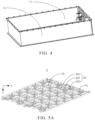
- the disclosure provides a battery pack 100 including a box body 1, a battery module 2, a cells contact system 3, and multiple heat-conducting portions 4.
- the box body 1 is provided with an accommodating cavity 11.
- the battery module 2 is disposed in the accommodating cavity 11.
- the cells contact system 3 is disposed in the accommodating cavity 11 and connected to the battery module 2.
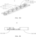
- the cells contact system 3 includes multiple busbars 31 and multiple insulating brackets 32.
- the multiple insulating brackets 32 are arranged at intervals.
- Each of the insulating brackets 32 is provided with one or more snap slot portions 33 recessed towards a first direction Y
- the busbars 31 are disposed in the snap slot portions 33.
- the heat-conducting portions 4 are disposed in the snap slot portions 33 and connected to a side of the busbars 31 away from the battery module 2.
- the heat generated is transferred from multiple cells in the battery module 2 to the busbars 31, then transferred from the busbars 31 to the heat-conducting portions 4, so as to dissipate the heat generated by the battery module 2, thereby improving lifetime and safety of the battery pack 100.
- the battery module 2 includes multiple cells arranged in an array and integrally formed.
- the cells contact system 3 includes multiple busbars 31. An end of each of the busbars 31 is connected to a positive electrode of one of adjacent two cells, and another end of the each of the busbars 31 is connected to a negative electrode of another one of the adjacent two cells.
- the multiple busbars 31 connect the multiple cells in series or parallel into a single unit for signal transmission and parameter collection.
- each of the heat-conducting portions 4 is adapted to the shape of one of the snap slot portions 33.
- each of the heat-conducting portions 4 when each of the snap slot portions 33 has a rectangular shape, each of the heat-conducting portions 4 is adapted to have a rectangular shape.
- the heat-conducting portions 4 may be made from heat-conducting gel, but not limited thereto. It can be determined according to the embodiments.
- the snap slot portions 33 are also used for accommodating the busbars 31, so a shape of the busbars 31 can be designed according to the shape of the snap slot portions 33 or the shape of the snap slot portions 33 can be designed according to the shape of the busbars 31.
- the shapes of the busbars 31 and the snap slot portions 33 may be square, triangular, circular, or other geometric shapes, but not limited thereto.
- the cells contact system (CCS) 3 further includes a flexible printed circuit (FPC), a collecting piece, and other components.
- the battery pack 100 further includes a battery management system (BMS).
- the cells contact system 3 is connected to the battery management system to realize signal transmission or information collection.
- the box body 1 includes a first liquid cooling plate 12 disposed at a side of the cells contact system 3 away from the battery module 2. A side of the first liquid cooling plate 12 close to the cells contact system 3 is connected to the heat-conducting portions 4.
- an orthographic projection of the first liquid cooling plate 12 in the first direction Y covers that of the battery module 2, so that heat generated by the battery module 2 is transferred to the busbars 31, then transferred from the busbars 31 to the heat-conducting portions 4. Because the heat-conducting portions 4 are attached to the first liquid cooling plate 12, the heat can be transferred from the heat-conducting portions 4 to the first liquid cooling plate 12, thereby improving the heat dissipation efficiency of the battery pack 100, and ensuring the lifetime and safety of the battery pack 100.
- the first water inlet channels 1231 and the first water outlet channels 1232 there is no limitation on the numbers of the first water inlet channels 1231 and the first water outlet channels 1232, as long as the heat dissipation purpose can be realized.
- the first water inlet channels 1231 are communicated with the first water inlet 121
- the first water outlet channels 1232 are communicated with the first water outlet 122
- an end of the first water inlet channels 1231 away from the first water inlet 121 are communicated with an end of the first water outlet channels 1232 away from the first water outlet 122.
- the multiple first water inlet channels 1231 for example, are parallel with each other and used for allowing the simultaneous flow of a cooling medium.
- the cooling medium flows from the first water inlet channels 1231 to the first water outlet channels 1232, absorbs the heat generated by the battery module 2 during the flow process, and then flows out from the first water outlet 122, so as to realize the heat dissipation of the battery pack 100.
- the box body 1 further includes a second liquid cooling plate 13 and multiple housing plates 14.
- the second liquid cooling plate 13 is opposite to the first liquid cooling plate 12.
- the multiple housing plates 14 are connected to each other. One end of the multiple housing plates 14 is connected to the second liquid cooling plate 13, and another end of the multiple housing plates 14 is connected to the first liquid cooling plate 12.
- the first liquid cooling plate 12, the second liquid cooling plate 13, and the multiple housing plates 14 form the accommodating cavity 11. Specifically, the second liquid cooling plate 13, and the first liquid cooling plate 12, and the housing plates 14 are connected, for example, through bolts.
- the second liquid cooling plate 13 is disposed at a side of the battery module 2 away from the cells contact system 3.
- the first liquid cooling plate 12 and the second liquid cooling plate 13 can dissipate heat from two ends of the battery module 2, improving the heat dissipation efficiency of the battery pack 100, and ensuring the lifetime and safety of the battery pack 100.
- the second liquid cooling plate 13 includes a second water inlet 131 and a second water outlet 132.
- the second water inlet 131 and the second water outlet 132 are disposed in the same side of the second liquid cooling plate 13.
- the cooling medium flows in from the second water inlet 131 and flows out from the second water outlet 132.
- the second liquid cooling plate 13 includes multiple liquid cooling channels. The multiple liquid cooling channels may be connected end to end, and the cooling medium flows out from the second water outlet 132 along the liquid cooling channels to realize the heat dissipation effect.
- the battery pack 100 further includes a heat-conducting layer 5 disposed between the battery module 2 and the second liquid cooling plate 13.
- the heat-conducting layer 5 may be made from heat-conducting adhesives, but not limited thereto.
- the heat-conducting layer 5 is disposed at a side of the battery module 2 away from the first liquid cooling plate 12, that is, between the battery module 2 and the second liquid cooling plate 13.
- the heat-conducting layer 5 is used for accelerating the transfer of heat, so that the heat can be transferred to the second liquid cooling plate 13 to realize the heat dissipation of the battery pack 100.
- a depth of one of the snap slot portions 33 in the first direction Y is greater than a height of corresponding one of the heat-conducting portions 4 in the first direction Y
- one of the snap slot portions 33 has a depth in the first direction Y to accommodate corresponding one of the busbars 31 and corresponding one of the heat-conducting portions 4.
- One of the heat-conducting portions 4 has a height in the first direction Y The height of one of the heat-conducting portions 4 cannot exceed the depth of corresponding one of the snap slot portions 33, which can be understood that the maximum height of one of the heat-conducting portions 4 in the first direction Y is not higher than the maximum depth of corresponding one of the snap slot portions 33 in the first direction Y
- each of the insulating brackets 32 includes a first insulating sub-bracket 321, a second insulating sub-bracket 322, and a third insulating sub-bracket 323. Opposite two ends of the second insulating sub-bracket 322 are connected to the first insulating sub-bracket 321 and the third insulating sub-bracket 323, respectively.
- the snap slot portions 33 are disposed in the first insulating sub-bracket 321 and the third insulating sub-bracket 323.
- the insulating brackets 32 are made from insulating materials, including, but not limited to, plastic.
- the multiple insulating brackets 32 are arranged at intervals to form a structure that can cover the battery module 2, so that each cell is connected to the busbars 31 in the insulating brackets 32, realizing the information transmission and heat transfer.
- the second insulating sub-bracket 322 is provided with multiple pressure relief holes 3221 penetrating the second insulating sub-bracket 322 in the first direction Y
- the multiple pressure relief holes 3221 are arranged at intervals in the second direction X and used for relieving pressure.
- the multiple pressure relief holes 3221 corresponds to the cells individually. When the battery pack 100 occurs thermal runaway, the cells release pressure through the pressure relief holes 3221.
- the multiple insulating brackets 32 can be an integrated structure to form a structure that can cover the battery module 2, so that each cell is connected to the busbars 31 in the insulating brackets 32, realizing the information transmission and heat transfer.
- multiple first insulating plates 32A include a first insulating plate 3211 and a first insulating plate 3231
- multiple second insulating plates 32B include a second insulating plate 3212 and a second insulating plate 3232
- multiple third insulating plates 32C include a third insulating plate 3213 and a third insulating plate 3233
- multiple avoidance portions 32D include an avoidance portion 3213a and an avoidance portion 3233a
- multiple fourth insulating plates 32E include a fourth insulating plate 3214 and a fourth insulating plate 3234.
- the first insulating sub-bracket 321 includes the first insulating plate 3211, the second insulating plate 3212, the third insulating plate 3213, and the fourth insulating plate 3214.
- the first insulating plate 3211 is disposed opposite to the second insulating plate 3212.
- An end of the third insulating plate 3213 is disposed on and surrounds the first insulating plate 3211, and another end of the third insulating plate 3213 is connected to the second insulating plate 3212 to form a cavity.
- the second insulating plate 3212 is provided with a snap slot hole extending in the first direction Y
- the fourth insulating plate 3214 is disposed in the cavity, an end of the fourth insulating plate 3214 surrounds the snap slot hole, and another end of the fourth insulating plate 3214 is connected to the first insulating plate 3211 to form one of the snap slot portions 33 in the first insulating sub-bracket 321.
- the third insulating sub-bracket 323 includes the first insulating plate 3231, the second insulating plate 3232, the third insulating plate 3233, and the fourth insulating plate 3234.
- the first insulating plate 3231 is disposed opposite to the second insulating plate 3232.
- An end of the third insulating plate 3233 is disposed on and surrounds the first insulating plate 3231, and another end of the third insulating plate 3233 is connected to the second insulating plate 3232 to form a cavity.
- the second insulating plate 3232 is provided with a snap slot hole extending in the first direction Y
- the fourth insulating plate 3234 is disposed in the cavity, an end of the fourth insulating plate 3234 surrounds the snap slot hole, and another end of the fourth insulating plate 3234 is connected to the first insulating plate 3231 to form one of the snap slot portions 33 in the third insulating sub-bracket 323.
- the cavities are filled with components, which can be understood as the first insulating sub-bracket 321 and the third insulating sub-bracket 323 served as insulating entities.
- the first insulating sub-bracket 321 and the third insulating sub-bracket 323 are provided with snap slot holes extending in the first direction Y, respectively.
- the snap slot holes are disposed in one end of the first insulating sub-bracket 321 and one end of the third insulating sub-bracket 323 close to the battery module 2.
- the snap slot holes penetrate or do not penetrate the first insulating sub-bracket 321 and the third insulating sub-bracket 323, and form one or more snap slot portions 33.
- the multiple snap slot portions 33 are arranged at intervals in the first insulating sub-bracket 321 and the third insulating sub-bracket 323, respectively, in the second direction X perpendicular to the first direction Y
- the multiple snap slot portions 33 are arranged at intervals in the second direction X and corresponding to the busbars 31. An end of one of the busbars 31 is connected to a positive electrode of one of adjacent two cells, and another end of one of the busbars 31 is connected to a negative electrode of another one of the adjacent two cells.
- the spacing between adjacent two snap slot portions 33 is adapted to the positions of adj acent two cells and one of the busbars 31.
- the snap slot portions 33 used for accommodating the output stage busbar and input stage busbar are adapted to shapes of the output stage busbar and the input stage busbar.
- a side of the fourth insulating plate 3214 and a side of the fourth insulating plate 3234 in the snap slot portions 33 away from the busbars 31 is provided with an avoidance space, respectively.
- a part of the output stage busbar and a part of the input stage busbar are both disposed in the avoidance spaces, and one end of the output stage busbar and one end of the input stage busbar extend outward, allowing the output stage busbar and the input stage busbar to be connected parallel to external components.
- the snap slot portions 33 are provided with multiple through holes 331 extending in the first direction Y, and the battery module 2 is connected to the busbars 31 disposed in the snap slot portions 33 through the through holes 331.
- the through holes 331 correspond to posts of the cells in position, but not limited thereto.
- the number of the through holes 331 corresponding to one cell may be two, so that the busbars 31 are connected to the cells by the through holes 331 to realize heat transfer.
- the heat-conducting portions 4 may be made from viscous heat-conducting gel, and the multiple avoidance portions 3233a cannot affect the heat-conducting performance of the heat-conducting portions 4 and the lifetime and safety of the battery pack 100.
- the multiple avoidance portions 3233a are arranged at intervals, and each of the avoidance portions 3233a has a width in the second direction X, and the width is designed to prevent excessive overflow of the heat-conducting portions 4.
- the avoidance portions 3213a and the avoidance portions 3233a are recessed towards the first direction Y
- the avoidance portions 3213a and the avoidance portions 3233a may extend to the first insulating plate 3211 and the first insulating plate 3231 under a maximum depression depth, and the specific depth is not limited in the disclosure.
- the battery pack 100 includes the box body 1, the battery module 2, the cells contact system 3, and multiple heat-conducting portions 4.
- the box body 1 is provided with the accommodating cavity 11; the battery module 2 is disposed in the accommodating cavity 11; the cells contact system 3 is disposed in the accommodating cavity 11 and connected to the battery module 2; the cells contact system 3 includes multiple busbars 31 and multiple insulating brackets 32, and the multiple insulating brackets 32 are arranged at intervals; each of the insulating brackets 32 is provided with multiple snap slot portions 33 recessed towards the first direction Y, and the busbars 31 are disposed in the snap slot portions 33; and the heat-conducting portions 4 are disposed in the snap slot portions 33 and connected to a side of the busbars 31 away from the battery module 2.
- the heat generated by the battery module 2 can be transferred to the busbars 31, then transferred from the busbars 31 to the heat-conducting portions 4 to realize heat dissipation.
- the first liquid cooling plate 12 and the second liquid cooling plate 13 are provided at two opposite ends of the battery module 2, respectively, in conjunction with the heat-conducting portions 4 and the heat-conducting layer 5, to accelerate heat transfer.
- the heat transferred to the heat-conducting portions 4 and the heat-conducting layer 5 is then transferred to the first liquid cooling plate 12 and the second liquid cooling plate 13, respectively, improving the heat dissipation efficiency of the battery pack 100, and ensuring the lifetime of the battery pack 100.
Landscapes
- Chemical & Material Sciences (AREA)
- Chemical Kinetics & Catalysis (AREA)
- Electrochemistry (AREA)
- General Chemical & Material Sciences (AREA)
- Engineering & Computer Science (AREA)
- Manufacturing & Machinery (AREA)
- Secondary Cells (AREA)
- Battery Mounting, Suspending (AREA)
Priority Applications (1)
| Application Number | Priority Date | Filing Date | Title |
|---|---|---|---|
| MA71654A MA71654A (fr) | 2023-11-29 | 2024-09-20 | Bloc-batterie |
Applications Claiming Priority (2)
| Application Number | Priority Date | Filing Date | Title |
|---|---|---|---|
| CN202323262303.4U CN221352931U (zh) | 2023-11-29 | 2023-11-29 | 电池包 |
| PCT/CN2023/142798 WO2025112155A1 (zh) | 2023-11-29 | 2023-12-28 | 电池包 |
Publications (2)
| Publication Number | Publication Date |
|---|---|
| EP4564528A2 true EP4564528A2 (de) | 2025-06-04 |
| EP4564528A3 EP4564528A3 (de) | 2025-06-18 |
Family
ID=92894747
Family Applications (1)
| Application Number | Title | Priority Date | Filing Date |
|---|---|---|---|
| EP24201666.5A Pending EP4564528A3 (de) | 2023-11-29 | 2024-09-20 | Batteriepack |
Country Status (3)
| Country | Link |
|---|---|
| US (1) | US20250174754A1 (de) |
| EP (1) | EP4564528A3 (de) |
| MA (1) | MA71654A (de) |
Family Cites Families (4)
| Publication number | Priority date | Publication date | Assignee | Title |
|---|---|---|---|---|
| CN103219834B (zh) * | 2013-03-29 | 2015-03-04 | 青岛中加特变频电机有限公司 | 3300v矿用隔爆兼本安型变频调速一体机 |
| CN218274872U (zh) * | 2022-06-16 | 2023-01-10 | 北京车和家汽车科技有限公司 | 电池包及车辆 |
| CN219163519U (zh) * | 2022-12-29 | 2023-06-09 | 远景动力技术(江苏)有限公司 | 电池包 |
| CN116960528A (zh) * | 2023-08-10 | 2023-10-27 | 深圳市华宝新能源股份有限公司 | 电池模组和储能电源 |
-
2024
- 2024-09-20 MA MA71654A patent/MA71654A/fr unknown
- 2024-09-20 EP EP24201666.5A patent/EP4564528A3/de active Pending
- 2024-10-18 US US18/920,662 patent/US20250174754A1/en active Pending
Also Published As
| Publication number | Publication date |
|---|---|
| US20250174754A1 (en) | 2025-05-29 |
| MA71654A (fr) | 2025-05-30 |
| EP4564528A3 (de) | 2025-06-18 |
Similar Documents
| Publication | Publication Date | Title |
|---|---|---|
| KR101326086B1 (ko) | 콤팩트한 구조와 우수한 방열 특성의 전지모듈 및 그것을 포함하는 중대형 전지팩 | |
| EP2366200B1 (de) | Batteriemodul mit hervorragender wärmeableitungsfähigkeit und batteriepackung damit | |
| US11990592B2 (en) | Battery, apparatus using battery, and manufacturing method and manufacturing device of battery | |
| US20120214041A1 (en) | Electricity storage module | |
| EP3920259A1 (de) | Batteriemodul und akkupack | |
| WO2014014623A1 (en) | Energy storage device and method | |
| CN113517505B (zh) | 电池组件和用电设备 | |
| CN218498164U (zh) | 一种便于固定的电池包液冷板及电池包 | |
| US20230216103A1 (en) | Battery pack and energy storage device | |
| CN217158321U (zh) | 电池包及车辆 | |
| CN111934052A (zh) | 液冷软包电池模组、电池系统及电动车辆 | |
| CN119742493A (zh) | 圆柱形电池单元封装和冷却配置 | |
| EP4564528A2 (de) | Batteriepack | |
| CN221352931U (zh) | 电池包 | |
| CN216213690U (zh) | 电池散热结构、电池箱体及电池结构 | |
| CN219979713U (zh) | 一种电芯组单元、电芯模组及集成电池包 | |
| CN214411312U (zh) | 散热模组及储能模组 | |
| CN223986631U (zh) | 一种电池包及用电装置 | |
| CN222282108U (zh) | 一种电池模组及电池包 | |
| CN223167533U (zh) | 换热组件和电池包 | |
| CN218069976U (zh) | 电池的水冷板及电池 | |
| CN223321334U (zh) | 电池液冷结构、电池箱体及电池包 | |
| CN217239579U (zh) | 动力电池包和动力装置 | |
| CN223598795U (zh) | 电池包及用电装置 | |
| CN217655953U (zh) | 冷却结构、动力电池包和动力装置 |
Legal Events
| Date | Code | Title | Description |
|---|---|---|---|
| PUAI | Public reference made under article 153(3) epc to a published international application that has entered the european phase |
Free format text: ORIGINAL CODE: 0009012 |
|
| STAA | Information on the status of an ep patent application or granted ep patent |
Free format text: STATUS: REQUEST FOR EXAMINATION WAS MADE |
|
| PUAL | Search report despatched |
Free format text: ORIGINAL CODE: 0009013 |
|
| 17P | Request for examination filed |
Effective date: 20240920 |
|
| AK | Designated contracting states |
Kind code of ref document: A2 Designated state(s): AL AT BE BG CH CY CZ DE DK EE ES FI FR GB GR HR HU IE IS IT LI LT LU LV MC ME MK MT NL NO PL PT RO RS SE SI SK SM TR |
|
| AK | Designated contracting states |
Kind code of ref document: A3 Designated state(s): AL AT BE BG CH CY CZ DE DK EE ES FI FR GB GR HR HU IE IS IT LI LT LU LV MC ME MK MT NL NO PL PT RO RS SE SI SK SM TR |
|
| RIC1 | Information provided on ipc code assigned before grant |
Ipc: H01M 50/209 20210101ALI20250509BHEP Ipc: H01M 10/6556 20140101ALI20250509BHEP Ipc: H01M 10/613 20140101AFI20250509BHEP |
|
| RAP3 | Party data changed (applicant data changed or rights of an application transferred) |
Owner name: EVE ENERGY STORAGE CO., LTD |
|
| STAA | Information on the status of an ep patent application or granted ep patent |
Free format text: STATUS: EXAMINATION IS IN PROGRESS |
|
| 17Q | First examination report despatched |
Effective date: 20260310 |