EP4564370A2 - Vorrichtung zur abschwächung eines signals aus einem nicht-analyten - Google Patents
Vorrichtung zur abschwächung eines signals aus einem nicht-analyten Download PDFInfo
- Publication number
- EP4564370A2 EP4564370A2 EP25151041.8A EP25151041A EP4564370A2 EP 4564370 A2 EP4564370 A2 EP 4564370A2 EP 25151041 A EP25151041 A EP 25151041A EP 4564370 A2 EP4564370 A2 EP 4564370A2
- Authority
- EP
- European Patent Office
- Prior art keywords
- analyte
- electrode
- sensor
- selective
- signal
- Prior art date
- Legal status (The legal status is an assumption and is not a legal conclusion. Google has not performed a legal analysis and makes no representation as to the accuracy of the status listed.)
- Pending
Links
Images


Classifications
-
- G—PHYSICS
- G16—INFORMATION AND COMMUNICATION TECHNOLOGY [ICT] SPECIALLY ADAPTED FOR SPECIFIC APPLICATION FIELDS
- G16H—HEALTHCARE INFORMATICS, i.e. INFORMATION AND COMMUNICATION TECHNOLOGY [ICT] SPECIALLY ADAPTED FOR THE HANDLING OR PROCESSING OF MEDICAL OR HEALTHCARE DATA
- G16H20/00—ICT specially adapted for therapies or health-improving plans, e.g. for handling prescriptions, for steering therapy or for monitoring patient compliance
- G16H20/10—ICT specially adapted for therapies or health-improving plans, e.g. for handling prescriptions, for steering therapy or for monitoring patient compliance relating to drugs or medications, e.g. for ensuring correct administration to patients
- G16H20/17—ICT specially adapted for therapies or health-improving plans, e.g. for handling prescriptions, for steering therapy or for monitoring patient compliance relating to drugs or medications, e.g. for ensuring correct administration to patients delivered via infusion or injection
-
- A—HUMAN NECESSITIES
- A61—MEDICAL OR VETERINARY SCIENCE; HYGIENE
- A61B—DIAGNOSIS; SURGERY; IDENTIFICATION
- A61B5/00—Measuring for diagnostic purposes; Identification of persons
- A61B5/145—Measuring characteristics of blood in vivo, e.g. gas concentration or pH-value ; Measuring characteristics of body fluids or tissues, e.g. interstitial fluid or cerebral tissue
- A61B5/14507—Measuring characteristics of blood in vivo, e.g. gas concentration or pH-value ; Measuring characteristics of body fluids or tissues, e.g. interstitial fluid or cerebral tissue specially adapted for measuring characteristics of body fluids other than blood
- A61B5/1451—Measuring characteristics of blood in vivo, e.g. gas concentration or pH-value ; Measuring characteristics of body fluids or tissues, e.g. interstitial fluid or cerebral tissue specially adapted for measuring characteristics of body fluids other than blood for interstitial fluid
- A61B5/14514—Measuring characteristics of blood in vivo, e.g. gas concentration or pH-value ; Measuring characteristics of body fluids or tissues, e.g. interstitial fluid or cerebral tissue specially adapted for measuring characteristics of body fluids other than blood for interstitial fluid using means for aiding extraction of interstitial fluid, e.g. microneedles or suction
-
- A—HUMAN NECESSITIES
- A61—MEDICAL OR VETERINARY SCIENCE; HYGIENE
- A61B—DIAGNOSIS; SURGERY; IDENTIFICATION
- A61B5/00—Measuring for diagnostic purposes; Identification of persons
- A61B5/145—Measuring characteristics of blood in vivo, e.g. gas concentration or pH-value ; Measuring characteristics of body fluids or tissues, e.g. interstitial fluid or cerebral tissue
- A61B5/14546—Measuring characteristics of blood in vivo, e.g. gas concentration or pH-value ; Measuring characteristics of body fluids or tissues, e.g. interstitial fluid or cerebral tissue for measuring analytes not otherwise provided for, e.g. ions, cytochromes
-
- A—HUMAN NECESSITIES
- A61—MEDICAL OR VETERINARY SCIENCE; HYGIENE
- A61B—DIAGNOSIS; SURGERY; IDENTIFICATION
- A61B5/00—Measuring for diagnostic purposes; Identification of persons
- A61B5/72—Signal processing specially adapted for physiological signals or for diagnostic purposes
- A61B5/7203—Signal processing specially adapted for physiological signals or for diagnostic purposes for noise prevention, reduction or removal
-
- A—HUMAN NECESSITIES
- A61—MEDICAL OR VETERINARY SCIENCE; HYGIENE
- A61B—DIAGNOSIS; SURGERY; IDENTIFICATION
- A61B5/00—Measuring for diagnostic purposes; Identification of persons
- A61B5/72—Signal processing specially adapted for physiological signals or for diagnostic purposes
- A61B5/7235—Details of waveform analysis
- A61B5/7264—Classification of physiological signals or data, e.g. using neural networks, statistical classifiers, expert systems or fuzzy systems
-
- G—PHYSICS
- G16—INFORMATION AND COMMUNICATION TECHNOLOGY [ICT] SPECIALLY ADAPTED FOR SPECIFIC APPLICATION FIELDS
- G16H—HEALTHCARE INFORMATICS, i.e. INFORMATION AND COMMUNICATION TECHNOLOGY [ICT] SPECIALLY ADAPTED FOR THE HANDLING OR PROCESSING OF MEDICAL OR HEALTHCARE DATA
- G16H40/00—ICT specially adapted for the management or administration of healthcare resources or facilities; ICT specially adapted for the management or operation of medical equipment or devices
- G16H40/60—ICT specially adapted for the management or administration of healthcare resources or facilities; ICT specially adapted for the management or operation of medical equipment or devices for the operation of medical equipment or devices
- G16H40/63—ICT specially adapted for the management or administration of healthcare resources or facilities; ICT specially adapted for the management or operation of medical equipment or devices for the operation of medical equipment or devices for local operation
-
- G—PHYSICS
- G16—INFORMATION AND COMMUNICATION TECHNOLOGY [ICT] SPECIALLY ADAPTED FOR SPECIFIC APPLICATION FIELDS
- G16H—HEALTHCARE INFORMATICS, i.e. INFORMATION AND COMMUNICATION TECHNOLOGY [ICT] SPECIALLY ADAPTED FOR THE HANDLING OR PROCESSING OF MEDICAL OR HEALTHCARE DATA
- G16H50/00—ICT specially adapted for medical diagnosis, medical simulation or medical data mining; ICT specially adapted for detecting, monitoring or modelling epidemics or pandemics
- G16H50/30—ICT specially adapted for medical diagnosis, medical simulation or medical data mining; ICT specially adapted for detecting, monitoring or modelling epidemics or pandemics for calculating health indices; for individual health risk assessment
-
- A—HUMAN NECESSITIES
- A61—MEDICAL OR VETERINARY SCIENCE; HYGIENE
- A61B—DIAGNOSIS; SURGERY; IDENTIFICATION
- A61B2560/00—Constructional details of operational features of apparatus; Accessories for medical measuring apparatus
- A61B2560/04—Constructional details of apparatus
- A61B2560/0462—Apparatus with built-in sensors
- A61B2560/0468—Built-in electrodes
Definitions
- the present invention generally relates to analyte-selective sensors and methods for configuration of the same, and a microneedle applicator integrated internally into a wearable sensor body housing.
- CGM continuous glucose monitor
- the integration of said sensing elements presents its own set of unique challenges, namely, developing robust methods for the integration of multiple sensing elements into a single transducer, minimizing undue interactions among said sensing elements, and the accurate deposition of unique analyte-selective and analyte-invariant sensing chemistries within the said transducer.
- the analyte sensing system is relegated to multiple electrodes comprised of adjacent metal wires or adjacent metal conduits on a flexible substrate.
- the synthesis of ever-more selective receptor molecules and diffusive flux-limiting membranes aims to increase sensor selectivity in the wake of the undue influence imparted by the complex array of endogenous (i.e. metabolites, hormones, neurotransmitters, small molecules) and exogenous (i.e. pharmaceuticals, supplements, drugs of abuse) analytes co-habilitating the physiological fluid.
- endogenous i.e. metabolites, hormones, neurotransmitters, small molecules
- exogenous i.e. pharmaceuticals, supplements, drugs of abuse
- Microneedle arrays require insertion within a specific velocity range.
- MNAs are a component of a mechanically rigid assembly including the electronics, housing, adhesive, and MNA mounted into a sensor body. Inserting this entire sensor body presents a number of challenges including accelerating the mass to speed with a force over a short distance, stretching the skin prior to accelerating the sensor body into the skin so that the skin will be tight and not displace away from the MNA on impact, releasing the sensor body subsequently from the applicator, along with a myriad of other concerns such as the total cost and size of the applicator and preventing unintended misuse of this complex multi-stage mechanism.
- Stretching the skin causes discomfort to the user and the impact of the sensor on the skin also causes discomfort to the user.
- analyte-selective sensor operates in a manner to enhance the selectivity towards a target analyte via the implementation of a receptor molecule (i.e. enzyme, antibody, aptamer), capture probe (i.e.
- analyte sensing systems have been constructed featuring both analyte-selective and analyte-invariant sensing elements, each embodying a unique chemical constituency, in order to ratiometrically scale the analyte-selective sensor response to mitigate external sources of undue signal influence.
- 4 in practice, noteworthy difficulties arise when attempting to deposit dissimilar chemistries on sensor geometries wherein both analyte-selective and analyte-invariant sensors are co-located within a single aggregated sensing element / transducer or intermingled in close proximity, which can lead to undesirable effects such as cross-talk.
- More recent efforts have been targeted at algorithmic and contextual methods of de-noising the analyte signal without requiring the addition of a second sensing modality, albeit these approaches have enjoyed very limited success.
- the ability to identify signal contributions which are non-analyte in origin enables the implementation of various mathematical methods to deconvolve or otherwise extricate the signal that is purely analyte-derived in origin from the signal arising from external influences.
- the current invention instructs of the implementation of at least two distinct sensing elements residing within a microneedle array, whereby at least one unique sensing element embodies the ability to quantify the presence of a target analyte (analyte-selective sensor) and is otherwise sensitive, albeit undesirably, to external stimuli and at least one unique sensing element which is not selective towards the presence of a target analyte (analyte-invariant sensor) and is otherwise sensitive, desirably, to external stimuli.
- the current invention instructs of devices and methods to mitigate the erroneous signal imparted by physical and/or chemical process incident upon analyte-selective electrochemical sensors that are non-analyte-related in origin. These processes often serve to corrupt the measurement signal tendered by said analyte-selective sensors.
- the solution described herein concerns the implementation of an analyte-invariant measure that is otherwise sensitive to physical and chemical perturbations incident upon the sensing system. This requires the construction of a sensing system featuring at least one of an analyte-selective sensor and at least one of an analyte-invariant sensor.
- the analyte-invariant sensor exhibits identical construction and constituency as the analyte-selective sensor sans the addition of an active biorecognition element, affinity molecule, catalyst, or capture probe that is selective towards the target analyte.
- a deactivated biorecognition element expressing no residual biospecific activity, may be included in the analyte-invariant sensor.
- the said active biorecognition element may be incorporated in the analyte-invariant sensor, but is subject to a deactivation process during sensor manufacture.
- any non-analyte signal perturbations will be incident upon both the analyte-selective and analyte-invariant sensing elements and can, through various mathematical transformations, be extricated from the fundamental analyte-derived signal in order to maximize the accuracy and reliability of the measurement.
- the mitigation of common-mode influences upon the analyte-selective sensor, which are also detected by the analyte-invariant sensor can be achieved and hence an overall improvement to the analyte signal fidelity (e.g., signal-to-noise ratio or similar characteristic) can be expected.
- Another objective is to eliminate the need to stretch the skin to insert a MNA.
- Anther objective is the ability to insert a wide variety of needles, dull or sharp, effectively.
- One aspect of the present invention is a device for the mitigation of a non-analyte-derived signal perturbation incident upon a body-worn, microneedle array-based analyte sensor.
- the device comprises a first electrode and a second electrode.
- the first electrode is positioned on a surface of a first microneedle of a microneedle array.
- a selective recognition element is disposed on the first electrode and configured to generate a product or change in physical state arising from the interaction of the selective recognition element and an analyte.
- a membrane is disposed on the selective recognition element.
- the second electrode is positioned on a surface of a second microneedle of the microneedle array, and a membrane is disposed on the second electrode.
- the first electrode and second electrode are positioned in spatially distinct locations within a viable epidermis or dermis of a user.
- a bias potential or current is applied to each of the first electrode and the second electrode.
- An ensuing electrical response from each of the first electrode and the second electrode is measured.
- a mathematical transformation is applied to the electrical response generated at the first electrode as a function of the electrical response generated at the second electrode to cause an attenuation of the common-mode signal.
- the device comprises a first electrode and a second electrode.
- a selective recognition element is disposed on the first electrode and configured to generate a product arising from the interaction of the selective recognition element and an analyte.
- a membrane is disposed on the selective recognition element.
- a membrane is disposed on the second electrode.
- the first electrode and second electrode are positioned in spatially distinct locations within a viable epidermis or dermis of a user.
- a bias potential or current is applied to each of the first electrode and the second electrode.
- An ensuing electrical response from each of the first electrode and the second electrode is measured.
- a mathematical transformation is applied to the electrical response generated at the first electrode as a function of the electrical response generated at the second electrode to cause an attenuation of the common-mode signal.
- Yet another aspect of the present invention is a device, with an analyte-selective sensor and an analyte-invariant sensor, for the mitigation of a non-analyte-derived signal perturbation incident upon a body-worn, analyte sensor.
- the device comprises an analyte-selective sensor and an analyte-invariant sensor.
- the analyte-selective sensor comprises a first electrode and a selective recognition element disposed on the first electrode and configured to generate a product or change in physical state arising from the interaction of the selective recognition element and an analyte.
- a membrane is disposed on the selective recognition element.
- An analyte-invariant sensor comprises a second electrode and a membrane disposed on the electrode.
- the analyte-selective sensor and the analyte-invariant sensor are positioned in spatially distinct locations within a viable epidermis or dermis of a user.
- a bias potential or current is applied to each of the analyte-selective sensor and the analyte-invariant sensor.
- An ensuing electrical response is measured from each of the analyte-selective sensor and the analyte-invariant sensor.
- a mathematical transformation is applied to the electrical response generated at the analyte-selective sensor as a function of the electrical response generated at the analyte-invariant sensor to cause an attenuation of the common-mode signal.
- Yet another aspect of the present invention is a method for the mitigation of a non-analyte-derived signal perturbation incident upon a body-worn, microneedle array-based analyte sensor.
- the method includes positioning a first microneedle and a second microneedle of a microneedle array in spatially distinct locations within the viable epidermis or dermis of a user, wherein said first microneedle features a first electrode, a selective recognition element disposed on said first electrode and configured to generate a product or change in physical state arising from the interaction of said selective recognition element and the analyte, and a membrane is disposed on the selective recognition element and the second microneedle features a second electrode and a membrane disposed on the second electrode.
- the method also includes applying a bias potential or current to each of the first electrode and the second electrode.
- the method also includes measuring an ensuing electrical response from each of the first electrode and second electrode.
- the method also includes applying a mathematical transformation to the said electrical response generated at the first electrode as a function of the said electrical response generated at the second electrode to cause an attenuation of the common-mode signal.
- Yet another aspect of the present invention is a method for the mitigation of a non-analyte-derived signal perturbation incident upon a body-worn, analyte sensor.
- the method includes positioning a first electrode and a second electrode of an analyte sensor in spatially distinct locations within the viable epidermis or dermis of a user, wherein the first electrode comprises a selective recognition element disposed on the first electrode and configured to generate a product or change in physical state arising from the interaction of the selective recognition element and the analyte, and a membrane is disposed on the selective recognition element and the second electrode comprises a membrane disposed on the second electrode.
- the method also includes applying a bias potential or current to each of the first electrode and the second electrode.
- the method also includes measuring an ensuing electrical response from each of the first electrode and the second electrode.
- the method also includes applying a mathematical transformation to the electrical response generated at the first electrode as a function of the electrical response generated at the second electrode to cause an attenuation of the common-mode signal.
- Yet another aspect of the present invention is a method for the mitigation of a non-analyte-derived signal perturbation incident upon a body-worn, analyte sensor system.
- the method includes positioning an analyte-selective sensor and analyte-invariant sensor of said analyte sensor system in spatially distinct locations within the viable epidermis or dermis of a user, wherein the analyte-selective sensor features a first electrode, a selective recognition element disposed on the first electrode and configured to generate a product or change in physical state arising from the interaction of the selective recognition element and the analyte, and a membrane disposed on the selective recognition element and the analyte-invariant sensor comprises a second electrode and a membrane disposed on the second electrode.
- the method also includes applying a bias potential or current to each of said analyte-selective sensor and analyte-invariant sensor.
- the method also includes measuring an ensuing electrical response from each of the analyte-selective sensor and the analyte-invariant sensor.
- the method also includes applying a mathematical transformation to the electrical response generated at the analyte-selective sensor as a function of the electrical response generated at the analyte-invariant sensor to cause an attenuation of the common-mode signal.
- the analyte preferably includes at least one of a biomarker, chemical, biochemical, metabolite, electrolyte, ion, hormone, neurotransmitter, vitamin, mineral, drug, therapeutic, toxin, pathogen, infectious agent, allergen, enzyme, protein, nucleic acid, DNA, and RNA.
- the analyte sensor system is preferably a microneedle or a microneedle array, with each microneedle constituent possessing a vertical extent preferably between 200 and 2000 ⁇ m.
- the microneedle or microneedle array preferably contains at least one projection capable of insertion into the viable epidermis or dermis of a user.
- the first electrode and the second electrode preferably include a metal, metal alloy, metal oxide, semiconductor, or polymeric surface.
- the first electrode and the second electrode are confined to the tapered distal region of the microneedle or the elements of the microneedle array.
- the selective recognition element preferably includes at least one of an enzyme, aptamer, antibody, capture probe, ionophore, catalyst, biocatalyst, DNA, RNA, organelle, or cell.
- the product is preferably a chemical, biochemical, mediator, resistance change, electrical signal, electrochemical signal, conductance change, impedance change, or absorbance change.
- the membrane is preferably at least one of a polymer, hydrophilic layer, biocompatible layer, diffusion-limiting layer, hydrogel, film, and coating.
- the bias potential or current is preferably either of the direct current or alternating current variety.
- the electrical response preferably includes at least one of a potential, current, impedance, conductance, resistance, capacitance, and inductance.
- the mathematical transformation preferably includes at least one of a difference operation, denoising operation, regression, deconvolution, Fourier decomposition, background subtraction, Kalman filtering, and Maximum Likelihood Estimation.
- the attenuation preferably includes at least one of the removal, minimization, or reduction in duration of the common-mode signal.
- the common-mode signal preferably includes at least one of a warm-up signal following application of the microneedle array-based analyte sensor to the skin of a wearer, a pressure-induced signal artefact, a temperature-induced signal fluctuation, and an interference signal originating from an endogenous or exogenous chemical species circulating in a physiological fluid of a user.
- the endogenous or exogenous chemical species preferably includes at least one of a biomarker, chemical, biochemical, metabolite, electrolyte, ion, hormone, neurotransmitter, vitamin, mineral, drug, therapeutic, toxin, pathogen, infectious agent, allergen, enzyme, protein, nucleic acid, DNA, and RNA.
- the physiological fluid is preferably at least one of interstitial fluid, dermal interstitial fluid, or blood of a user.
- Body-worn analyte-selective sensors such as continuous glucose monitors
- This accuracy can be unduly influenced by various external stimuli, which gives rise to undesired perturbations of the signal or signals transduced from said analyte-selective sensors, thereby introducing error in measurement and undermining the ultimate accuracy achievable with such devices.
- external perturbations which may be chemical, electrical, or mechanical in origin.
- the current innovation is aimed at mitigating the preponderance of undue physical, chemical, and otherwise exogenous influences upon the fidelity of the measurement of the target analyte or plurality of analytes.
- This is achieved via implementation of at least one of an analyte-selective sensor and at least one of an analyte-invariant sensor, whereby the said analyte-selective sensor features a selective recognition element and said analyte-invariant sensor lacks said selective recognition element but is otherwise identical in construction and constituency to said analyte-selective sensor.
- the common-mode signal appearing at both the analyte-selective and analyte-invariant sensors may be minimized, mitigated, or eliminated entirely, thereby resulting in an analyte signal of greater fidelity and/or accuracy.
- FIG. 1 shows a block diagram 10 illustrating the use of an analyte-invariant (Non-Enzyme) signal 11 in conjunction with an analyte-selective (Current Ch1, Ch2, Ch3) signal 13 to de-noise the analyte signal 14 (Current Ch1 Clean, Ch2 Clean, Ch3 Clean). **What about Temp signal 12? Process 1 / RLSfilter 15?
- the said device is configured to feature at least one of an analyte-selective sensor and at least one of an analyte-invariant sensor, both located on unique microneedle constituents of the array, as show in FIG. 17A .
- said analyte-selective sensor is configured to feature an electrode 40a on the surface of a first microneedle 30a of said microneedle array, a selective recognition element 41 disposed on said first electrode 40a and configured to generate a product arising from the interaction of said selective recognition element 41 and said analyte, and a membrane disposed 42 on said selective recognition element 41.
- said analyte-invariant sensor is configured to feature an electrode 40b on the surface of a second microneedle 30b of said microneedle array, and a membrane 43 disposed on said electrode.
- Said analyte-selective and analyte-invariant sensors are disposed in said microneedle array to facilitate sensing operation in spatially distinct locations within the viable epidermis 131 or dermis 132 of a user, as shown in FIG. 16 , thereby serving to minimize any undue influence or cross-talk from one sensor to another.
- an identical or unique bias signal DC or AC potential or current
- an ensuing electrical response is measured from both the said first electrode and second electrode.
- a mathematical transformation is subsequently applied to the said electrical response generated at the first electrode as a function of the said electrical response generated at the second electrode to remove the common-mode signal incident upon both analyte-selective and analyte-invariant sensors.
- These mathematical transformations can include differential (subtractive) measurement, deconvolution, Fourier decomposition, background subtraction, Kalman filtering, and Maximum Likelihood Estimation.
- the analyte-selective sensor is configured to feature an electrode 40a on the surface of a first microneedle 30a of the microneedle array, a selective recognition element 41 disposed on the first electrode 40a and a membrane disposed 42 on the selective recognition element 41 and on the second electrode 40b of the second microneedle 30b.
- the senor is configured to feature an electrode 40a on the surface of a first microneedle 30a of the microneedle array, and a membrane 42 containing a selective recognition element 41 disposed on the first electrode 40a.
- a membrane 43 is disposed on the second electrode 40b on the surface of a second microneedle 30b.
- each microneedle 30 of the microneedle array 20 preferably has a through-silicon via 33 embedded within a microneedle 30.
- the microneedle 30 preferably has insulation 34 composed of an oxide. This allows the sensors to be individually probed as isolated constituents of the microneedle array 20.
- the microneedle array preferably can be reflow-soldered to nearly any circuit board just like an integrated circuit.
- Each microneedle 30 preferably has an individual sensor 31 confined to a distal tip of the microneedle 30, preferably in a region between 1 and 1500 ⁇ m from the distal end of the microneedle 30.
- the microneedle 30 preferably has a backside metal contact 32, a through needle VIA 33, insulation 34 to electrically isolate the microneedle 30 and a patterned metal contact 35 on the distal tip 36 of the microneedle 30.
- the backside metal contact 32 is preferably composed of a nickel/gold material with an interior portion 37 composed of an aluminum material.
- the microneedle 30 preferably has a through needle VIA 33 composed of a silicon material.
- the distal tip 36 preferably has oxide portions and platinum portions.
- the length, Lm, of the microneedle 30 preferably ranges from 200-2000 ⁇ m, and is most preferably 625 ⁇ m.
- the width, Wm, of the microneedle 30 preferably ranges from 100 to 500 ⁇ m, and is most preferably 160 ⁇ m.
- the distal tip 36 preferably has a length, Ld, ranging from 50 to 200 ⁇ m, and is most preferably 100 ⁇ m.
- the devices and methods presented are capable of the determination of analytes that comprise at least one of a biomarker, chemical, biochemical, metabolite, electrolyte, ion, hormone, neurotransmitter, vitamin, mineral drug, therapeutic, toxin, enzyme, protein, nucleic acid, aptamer, DNA, and RNA.
- these systems employ microneedle arrays containing at least two projections capable of insertion into the viable epidermis or dermis of a user, wherein each projection possesses an extent between 200 and 2000 micrometers from proximal to distal extremities.
- the electrode constituent discussed above is confined to the distal region of the aforementioned protrusions and includes a metal, semiconductor, or polymeric surface.
- the selective recognition element discussed includes at least one of an enzyme, aptamer, antibody, capture probe, ionophore, catalyst, biocatalyst, DNA, RNA, organelle, or cell and is configured to produce a chemical, biochemical, mediator, resistance change, electrical signal, conductance change, impedance change, or absorbance change upon exposure to the analyte.
- the abovementioned membrane is at least one of a polymer, hydrophilic layer, biocompatible layer, diffusion-limiting layer, hydrogel, film, and coating.
- novel and utilitarian features of the invention includes its intrinsic ability to negate the effect of cross-talk due to diffusive transport of product from analyte-selective to analyte-invariant sensor.
- the invention also reduces the influence of the analyte depletion region or diffusion layer effects, which serves to limit the quantity of analyte that can diffuse to an analyte-selective sensor.
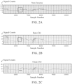
- FIGS. 2A-2C show raw signal traces originating from an analyte-invariant sensor (Non-Enzyme), as shown in FIG 2A , and an analyte-selective sensor (Raw-Ch 1), as shown in FIG. 2B , illustrating the common-mode signal perturbation highlighted in the red square.
- the implementation of a mathematical transformation allows the removal of the said common-mode signal perturbation (red line), as shown in FIG. 2C , which is non-analyte in origin as it appears at both the analyte-invariant and analyte-selective sensors.
- FIGS. 3A-3C show raw signal traces originating from a plurality of analyte-selective sensors (Raw-Ch1, Ch2, Ch3), as shown in FIG. 3A , and an analyte-invariant sensor (Non-Enzyme), as shown in FIG. 3B , illustrating the 2 hour warm-up period required for sensor equilibration following implantation into tissue.
- the implementation of a mathematical transformation allows the reduction of the apparent warm-up period to less than 1 hour, as shown in FIG. 3C .
- the warm-up period is non-analyte in origin as it appears at both the analyte-invariant and analyte-selective sensors.
- FIG. 4 shows a bar chart illustrating improvements to analyte-selective sensor accuracy (as evidence by mean absolute relative difference - MARD) on day 1 of sensor use by means of extending the warm-up period or implementation of an algorithm configured to subtract the analyte-invariant sensor signal from the analyte-selective sensor signal.
- the true analyte signal is isolated by differential measurement:
- True Analyte Signal Analyte selective Sensor Signal - Analyte invariant Sensor Signal
- Convolutional methods may be employed to extricate the pure analyte-selective signal component from other sources of noise.
- M NORM j ⁇ A NORM j ⁇ N NORM j ⁇
- a NORM j ⁇ M NORM j ⁇ / N NORM j ⁇
- SNR signal-to-noise ratio
- NF SNR i SNR o
- SNR i is the signal-to-noise ratio of the system at a specified analyte level
- SNR o is the measured signal-to-noise ratio embodied by a particular measurement.
- CMRR common-mode rejection ratio
- the non-analyte effect is assumed to be additive, this is due to the fact that multiplicative models represent a greater challenge to solve.
- an adaptive filter would adjust the coefficients of a time-varying filter W(n) to regress the non-analyte signal into s(n).
- the cost function is defined as: min norm W ′ i ⁇ s , 2 .
- RLS Recursive Least Squares
- LMS Least Mean Squares
- KF Kalman Filter
- KAF Kernel Adaptive filtering
- FIGS. 5-10 show block diagrams of the process flow of the sensors.
- FIG. 5 shows a prior art analyte-selective sensor block diagram.
- the non-analyte signal is additive to the analyte signal.
- FIG. 6 shows an analyte-invariant sensor.
- FIG. 7 shows a system to remove the perturbations to the analyte signal that are non-analyte (and additive) in origin.
- FIG. 8 shows a system to remove the perturbations to the analyte signal that are non-analyte (and additive) in origin.
- FIG. 9 shows a system to remove the common-mode signal arising from perturbations that are non-analyte in origin.
- the analyte signal is modulated by the common-mode signal whereas the analyte-invariant sensor is directly sensitive to the common-mode signal.
- FIG. 10 shows a system to remove the common-mode signal arising from perturbations that are non-analyte in origin.
- the analyte signal is modulated by the common-mode signal whereas the analyte-invariant sensor is directly sensitive to the common-mode signal.
- FIG. 11 shows a block diagram 180 of a device to remove signal perturbations that are non-analyte in origin.
- the analyte-selective sensor contains a membrane with an analyte / biorecognition element.
- the analyte-invariant sensor contains a membrane lacking an analyte / biorecognition element.
- the analyte-selective sensor and analyte-invariant sensor are at least two distinct electrodes.
- the analyte-selective sensor is located on an electrode on at least one microneedle of a microneedle array.
- the analyte-invariant sensor is located on at least one microneedle of a microneedle array.
- the analyte sensor is a microneedle array.
- the analyte sensor system is an analyte-selective microneedle array sensor.
- the analyte-selective microneedle array sensor is body-worn on the skin surface of a user.
- the algorithm is processed internally in the device.
- the algorithm is processed in a wirelessly-connected device.
- the algorithm is processed in a Cloud service.
- the analyte measurement is provided to the user on a display. In other embodiments, the analyte measurement is used to guide therapeutic interventions in an automated insulin delivery system. In yet another embodiment, the analyte measurement is delivered to a wirelessly-connected device. In yet another embodiment, the analyte measurement is stored in a Cloud service.
- Step 201 is positioning a first microneedle and a second microneedle of the microneedle array in spatially distinct locations within the viable epidermis or dermis of a user.
- the first microneedle features a first electrode, a selective recognition element disposed on the first electrode and configured to generate a product arising from the interaction of the selective recognition element and the analyte, and a membrane disposed on the selective recognition element and the second microneedle features a second electrode and a membrane disposed on the second electrode.
- Step 202 is applying a bias potential or current to each of the first and second electrodes.
- Step 203 is measuring an ensuing electrical response from each of the first and second electrodes.
- step 204 is applying a mathematical transformation to the electrical response generated at the first electrode as a function of the electrical response generated at the second electrode to cause an attenuation of the common-mode signal.
- Step 206 starts with positioning a first electrode and a second electrode of the analyte sensor in spatially distinct locations within the viable epidermis or dermis of a user.
- the first electrode features a selective recognition element disposed on the first electrode and configured to generate a product arising from the interaction of the selective recognition element and the analyte, and a membrane disposed on the selective recognition element and the second electrode features a membrane disposed on the second electrode.
- Step 207 is applying a bias potential or current to each of the first and second electrodes.
- Step 208 Measuring an ensuing electrical response from each of the first and second electrodes is step 208.
- Step 209 is applying a mathematical transformation to the electrical response generated at the first electrode as a function of the electrical response generated at the second electrode to cause an attenuation of the common-mode signal.
- Step 211 is positioning an analyte-selective sensor and analyte-invariant sensor of the analyte sensor system in spatially distinct locations within the viable epidermis or dermis of a user.
- the analyte-selective sensor features a first electrode, a selective recognition element disposed on the first electrode and configured to generate a product arising from the interaction of the selective recognition element and the analyte.
- a membrane disposed on the selective recognition element, and the analyte-invariant sensor features a second electrode and a membrane disposed on the second electrode.
- Applying a bias potential or current to each of the analyte-selective sensor and analyte-invariant sensor is step 212.
- Step 213 is measuring an ensuing electrical response from each of the analyte-selective sensor and analyte-invariant sensor.
- Step 214 is applying a mathematical transformation to the electrical response generated at the analyte-selective sensor as a function of the electrical response generated at the analyte-invariant sensor to cause an attenuation of the common-mode signal.
- FIG. 19 illustrates the electronic circuitry contained in a wearable device enclosure 60 designed to interface directly with a microneedle-based biosensor device.
- the electronic circuitry of the device comprises a wireless transceiver (preferably BLUETOOTH LOW ENERGY) and a microcontroller with an integrated analog-to digital converter 61, and a high amplification circuit 62.
- FIG. 20 illustrates another view of the electronic circuitry contained in prototype wearable device enclosure 60 designed to interface directly with a microneedle-based biosensor device.
- the electronic circuitry comprises a high-sensitivity electrochemical analog front end 63 and a filtering circuit 64.
- FIG. 21 illustrates the electronic circuitry contained in the wearable device enclosure 60 with access to the microneedle device provided via gold-plated pressure connectors 67 located on the viewable surface of the wearable device enclosure 60.
- a connection port 65 is also shown.
- FIG. 22 illustrates a skin-penetrating hollow microneedle array 70 comprising a plurality of protrusions having vertical extent of approximately 1000 ⁇ m, with each element of the microneedle array functionalized to impart selective biosensing ability.
- FIG. 23A illustrates a hollow, unfunctionalized microneedle array 70a.
- FIG. 23B illustrates a hollow "filled", functionalized microneedle array 70b with selective biosensing ability.
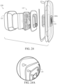
- FIGS. 24 and 24A illustrate an exploded view rendering of complete microneedle biosensing system 120 illustrating the functional components, including a housing member 125, a microneedle biosensor 130 and a printed circuit board 127 containing the electronic circuitry required to transduce biochemical signals to digital data that are wirelessly transmitted to an external device via the embedded wireless transceiver.
- FIG. 25 illustrates a top perspective view of the wearable microneedle biosensing system 120 containing the electronic backbone (protrusion) and adhesive patch.
- the microneedle is located on the posterior surface of the adhesive patch (not shown).
- FIG. 26 illustrates a posterior surface view of the electronics components housing constituent 130 of the microneedle-based biosensing system 120 and the skin-worn adhesive patch containing the microneedle array 127.
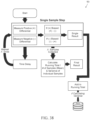
- FIG. 27 illustrates a detailed block/process flow diagram 1200 illustrating the major functional components of the microneedle-based biosensing system and supporting electronic systems.
- the microneedle array utilized to obtain transdermal biochemical analytes from a viable physiological medium (interstitial fluid, blood) occupying the layers of the epidermis and dermis of a user of the microneedle-based biosensing system.
- the electrochemical analog front end performs one (or more) of a number of electroanalytical techniques, such as voltammetry, amperometry, potentiometry, conductimetry, impedimetry, and polarography, to facilitate the control and readout of the electrochemical reaction occurring at the microneedle-based biosensing system.
- the electrical signal generated at the output of the electrochemical analog front end is directed to an amplification circuit to increase the signal strength to line levels.
- the output from the amplification circuit is directed to a low- or band-pass filter to extract a signal of interest and remove any undesired noise.
- the signal subsequently undergoes analog-to-digital conversion at an ADC to convert the analog signal to a digital bitstream.
- the signal is routed to a wireless transmitter or transceiver (BLUETOOTH, WiFi, RFID / NFC, Zigbee, Ant+) 1207 for transmission of the signal (corresponding to the level of the biochemical analyte) to a mobile communication device 1208 for further information processing, interpretation, display, archiving, and trending.
- BLUETOOTH wireless transmitter or transceiver
- the electrochemical analog front end preferably includes: a Texas Instruments LMP91000 Sensor AFE System, configurable AFE potentiostat for low-power chemical sensing applications; a Texas Instruments LMP91200 configurable AFE for low-power chemical sensing applications; or an Analog Devices ADuCM350 16-Bit Precision, low power meter on a chip with Cortex-M3 and connectivity.
- the wireless transceiver is preferably is a BLUEGIGA BLE-113A BLUETOOTH Smart Module, or a Texas Instruments CC2540 SimpleLink BLUETOOTH Smart Wireless MCU with USB.
- the accompanying mobile device is preferably an ANDROID TM - or iOS TM -based smartphone, Samsung GALAXY GEAR, or an APPLE WATCH TM .
- the microneedle array electrochemical biosensor transduces biochemical signals from the interstitial fluid into useful electrical signals.
- the electrochemical analog front end preferably performs at least one or more of the following: applies a fixed potential or time-varying potential to the microneedle array to induce an electrochemical reaction, thereby giving rise to a flow of current; applies a fixed current or time-varying current to the microneedle array to induce an electrochemical reaction, thereby giving rise to an electrical potential; measures a time-varying open-circuit potential generated by an electrochemical reaction or ionic gradient; measures a frequency-dependent impedance generated by an electrochemical or bio-affinity reaction at the microneedle transducer; and measures a specific resistance or conductance generated by an electrochemical or bio-affinity reaction at the microneedle transducer.
- the electrochemical analog front end is preferably dynamically configured to achieve any one of the above-numerated embodiments.
- the inputs are preferably arrayed to operate sequentially or in parallel to expand the sensing capabilities of the system.
- the wireless transceiver wirelessly relays electrical signals generated by the electrochemical analog front end to a mobile or wearable device using any one of a number of standardized wireless transmission protocols (Bluetooth, WiFi, NFC, RFID, Zigbee, Ant+).
- the electrical signal generated by the analog front end can be amplified, filtered, and/or undergo analog-to-digital-conversion and further signal processing prior to being relayed by the wireless transceiver.
- the mobile or wearable device displays sensor readings to the user in an easily-understood format, and performs any additional signal processing necessary.
- an adjustable bias analog front end / potentiostat 69 is composed of high-input impedance operational amplifiers and a digital to analog converter, or a standalone analog front end (“AFE”) or analog interface integrated circuit package.
- FIG. 29 is a circuit diagram of a multi-component potentiostat 230 with an electrochemical cell 71.
- the potentiostat/AFE unit consists of either two ( FIG. 28 ) or three ( FIG. 29 ) precision instrumentation operational amplifiers (A1/OA1, OA2, and TIA/OA3) configured in the following arrangement: control amplifier A1/OA1 amplifies the differential voltage (V x in FIG. 20 ) measured between a variable (programmable) bias and ground (with gain A) and supplies current through the counter electrode (CE). Upon sensing a voltage generated at the reference electrode (RE), A1/OA1 sinks sufficient current in order to maintain its output voltage at the input (V RE ) value. In turn, RE is adjusted and the output potential/current of A1/OA2 (a buffer or unity-gain amplifier) is modified accordingly.
- A1/OA1 amplifies the differential voltage (V x in FIG. 20 ) measured between a variable (programmable) bias and ground (with gain A) and supplies current through the counter electrode (CE).
- CE counter electrode
- A1/OA1 sinks sufficient current in order to maintain its output voltage at the input (V RE )
- the control amplifier thus functions as a voltage-controlled current source that delivers sufficient current to maintain the reference electrode at constant potential and arbitrate the electrochemical reaction.
- A1/OA2 be able to swing to extreme potentials to allow full voltage compliance required for chemical synthesis.
- the OA2 possesses very high input impedance in order to draw negligible current; otherwise the reference electrode may deviate from its intended operating potential.
- the use of precision amplifiers possessing 20 fA (or lower) of input bias current enables unabated operation to the sub-picoampere level, which is suitable for nearly all electrochemical studies.
- the TIA/OA3 accepts the current sourced through the working electrode (WE) and outputs a voltage (converted by resistor/capacitor network R TIA /C 5 +R 4 ) proportional to the amount of current passing through electrode WE.
- the difference amplifier stage 75 is shown in FIG. 30 .
- the difference amplifiers are configured to accept the applied reference voltage (RE or C1 in the internal IC diagram) and the output from the transimpedance amplifier (with or without a buffer stage).
- the inputs are juxtaposed among the two amplifiers, namely the reference input is connected to the positive terminal on one of the amplifiers (for negative applied voltages/currents) and on the negative terminal of the other (for positive applied voltages/currents).
- VOUT is connected to the opposing amplifier input.
- the unused amplifier opposite the polarity of the applied current/voltage
- the gain of the difference amplifier can be configured either through manufacture or in real time to scale to the amount of voltage/current read in by the AFE.
- the Filtering step The outputs generated from the difference amplifier pair are subsequently subjected to a filtering circuit to remove extraneous noise. Oscillations or random fluctuations in the signal can be present due to a number of reasons, including ground bias, RF interference, mains power oscillation, input impedance mismatch (from the 3 electrode sensor), or from other sources.
- the Analog to Digital Converter step The filtered signals are lastly incident upon an analog to digital converter ("ADC"), either located in an external integrated circuit (“IC”), or co-located within a microcontroller or other IC, and converted into a representative digital signal.
- ADC analog to digital converter
- IC integrated circuit
- microcontroller or other IC microcontroller or other IC
- Increased sampling resolution may be implemented to gain additional sensitivity and minimize quantization error.
- the Collection Algorithm step To further reduce noise, a time averaged value for both positive and negative bias lines will be collected and computed by a microcontroller/microprocessor over a period of a few seconds (subsequent to digitization by the ADC).
- the active bias amplifier (applied voltage/current) will have the value of the inactive bias amplifier (ground offset) subtracted in order to remove any present bias in the device. Due to this process, a shielding cage is not required to reach picoampere levels of sensitivity.
- the inactive bias amplifier, time average data collection, and filtering schemes will provide a stable and scalable output into the microcontroller/processor at all times.
- the input of the electrochemical cell or sensor, the analyte is measured by controlled-potential techniques (amperometry, voltammetry, etc).
- the output of the sensing system consisting of a measured voltage and calculated current value (determination of current flowing through working and counter electrodes of electrochemical cell or sensor), corresponds to the concentration of the analyte in the sample.
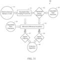
- FIG. 31 illustrates a signal flow diagram 80 for detecting a current flowing an electrochemical cell.
- a current signal from an electrochemical cell 66 is sent to an adjustable bias analog front end 81.
- the signal is sent to a transimpedance amplifier 82.
- the signal is sent from both the adjustable bias analog front end 81 and the transimpedance amplifier 82 to mirrored difference amplifiers 84.
- the outputs generated from the mirrored difference amplifiers 84 are subsequently subjected to filtering circuits 86 and 87 to remove extraneous noise. Oscillations or random fluctuations in the signal can be present due to a number of reasons, including ground bias, RF interference, mains power oscillation, input impedance mismatch (from the 3 electrode sensor), or from other sources.
- a time averaged value for both positive and negative bias lines is collected and computed by a microcontroller/microprocessor over a suitable time period, such as a few seconds (subsequent to digitization by the ADC).
- the active bias amplifier (applied voltage/current) will have the value of the inactive bias amplifier (ground offset) subtracted in order to remove any present bias in the device. Due to this process, a shielding cage is not required to reach picoampere levels of sensitivity.
- the inactive bias amplifier, time average data collection, and filtering schemes will provide a stable and scalable output into the microcontroller/processor/ADC at all times.
- FIG. 32 is a detailed circuit diagram of an integrated analog front end 150 and sensor interface.
- This is a circuit diagram of an integrated AFE available from a manufacturer that communicates (SCL and SDA lines) with a central microcontroller/microprocessor unit and controls an electrochemical sensor via the CE (counter electrode), WE (working electrode), and RE (reference electrode) lines.
- the configurable circuit components for the transimpedance amplifier (TIA) are present across 9 and 10 and forms an integrator as configured in the image.
- FIG. 33 is a detailed circuit diagram of mirrored difference amplifiers 84' and filtering.
- a set of mirrored difference amplifiers is shown utilizing individual operational amplifier components (left side) and a low pass filter on the output(right side).
- AMORP and AMORN are the positive and negative differential signals
- AMOUTN and AMOUTP are the filtered differential signals. Output gain is controlled by the passive resistors connected to the amplifiers.
- FIG. 34 is a detailed circuit diagram of fixed mirrored instrumentation amplifiers 84a and 84b. Here, a set of mirrored difference amplifiers is shown using a pair of integrated instrumentation amplifiers. Output gain is controlled by a single resistor connected to the RG terminals.
- FIG. 35 is a detailed circuit diagram of digital potentiometer-adjustable mirrored instrumentation amplifiers 84c. This is similar to FIG. 34 , albeit utilizing a programmable/digitally selectable gain resistor integrated circuit (IC3) rather than passive components.
- IC3 programmable/digitally selectable gain resistor integrated circuit
- FIG. 36 is an illustration of a handheld analyzer 220 in a large form factor.
- FIG. 37 is an illustration of a handheld analyzer 220a in a small form factor.
- FIG. 39 is an illustration of a handheld analyzer 220b in a small form factor.
- each "sample” involves reading both the positive and negative differential outputs and subtracting one from the other. Multiple samples can be collected and analyzed via statistical operations to yield a measurement. The simplest form is to calculate mean and variance/standard deviation from a set of individual samples. The sampling period has to be selected in a manner that minimizes the possibility of noise from other electrical sources.
- the main sources of noise are: floating ground and ground drift; mains power; and high frequency interference.
- the floating ground and ground drift are compensated by various means. Floating ground (DC noise) is compensated by the presence of the paired difference amplifiers. Ground drift is compensated by averaging multiple samples. If measuring a positive bias/current, the negative output will be equal to the floating ground. Subtracting the negative output from the positive will remove noise caused by ground drift. The opposite can be performed when measuring a negative bias/current. The subtraction step should be performed at each sample rather than using averages of multiple readings.
- Mains Power is also compensated in various ways. Noise arising due to mains power when either connected to an AC power line or induced by proximity to other AC line-powered equipment is compensated by selection of the algorithm sampling period. Sampling should never be performed at the same delay as the period of the line power cycle (16 or 20 ms for 60 Hz and 50 Hz power systems, respectively) or any multiple thereof (i.e. 32 to 40 ms for a multiple of two, etc). If sampling delay is less than the line power cycle (16-20 ms), at least one cycle (at 50-60 Hz) must be captured by multiple samples. For proper statistical analysis, enough samples must be collected to establish an adequate estimate of the standard deviation and mitigate power line harmonics.
- Type 1 false positive
- Type 2 false negative
- at least 13 samples must be measured. This is application-specific but a minimum of 10 samples is recommended.
- the maximum sample number is application-dependent (the likelihood of sudden changes due to external factors, such as movement in the case of a body worn sensor).
- NNs neural networks
- the input to the NN comprises the input measurements and the network is trained a priori on desired signal measurement (i.e. interstitial glucose values).
- desired signal measurement i.e. interstitial glucose values
- the network is trained, using either supervised or unsupervised learning methods, to develop a mathematical model mapping between signal (i.e. electrical current), temperature, non-analyte and other sources of interference and the target desired analyte signal.
- signal i.e. electrical current
- temperature i.e. electrical current
- non-analyte and other sources of interference i.e. electrical current
- Other sources of interference i.e. electrical current
- target desired analyte signal i.e. electrical current
- Different forms of deep and shallow neural networks might be built with combination of following layers: Recurrent Neural Networks; Convolutional Neural Networks.
- real-time convex optimization is employed to deconvolve the undesired effects by constructing regression cost functions that have additional penalizing factors in their cost function in order to apply prior knowledge of smoothness or other frequency-based knowledge of the interreference signals.
- Projection techniques such as linear and nonlinear (kernel) Principal Component Analysis (PCA) and Independent Component Analysis (ICA) are also employed in selected embodiments for blind source separation.
- the input matrix X contains all the signals, including analyte-selective and non-analyte-selective signals, as well as any extraneous signal readouts, such as temperature.
- PCA Principal Component Analysis
- ICA Independent Component Analysis
- Continuous Wavelet Transform (CWT) of the analyte-selective and analyte-invariant sensor measurements are computed in certain embodiments so that a two-dimensional corresponding time-frequency of non-analyte and 'contaminated' analyte signal measurements can be constructed.
- the corresponding coefficients of frequencies that are correlated between the reference non-analyte and contaminated analyte signals in time are set to zero to remove the said effects.
- Non-analyte-derived signal perturbations observable in analyte-selective sensors can claim origin from a plethora of physio-chemical processes, some of which are endogenous to the biological milieu while others arise due to exogenous effects instigated by the wearer of said sensors.
- body-worn analyte-selective sensors often succumb to pressure-induced signal irregularities due to the inadvertent application of pressure or force onto the said sensor enclosure or housing; these are referred to as pressure-induced sensor attenuations (PISAs). This oftentimes is caused by induced changes in perfusion to the sensor or localized depletion of the analyte of interest or co-factor, such as oxygen.
- the disruption of the diffusion layer is also a cause of said PISA events since the sensing operation enabled by said analyte-selective sensors is diffusion-limited in nature.
- the execution of an analyte-invariant measure enables the identification of these instances, especially in the acute phase, as it is generally understood that the response of said analyte-invariant sensor is largely immune to said PISA events.
- all electrochemical sensors undergo a non-Faradaic process immediately following excitation with an electrical stimulus wherein the ensuing signal response is not proportional to analyte concentration by the Cottrell relation, but rather the charging of the double-layer capacitance through the solution resistance.
- An analyte-invariant sensor undergoing the same non-Faradaic signal decay as an analyte-selective sensor may be employed in a differential configuration to extricate the true analyte signal from the non-Faradaic signal response.
- implanted analyte-selective sensors require a certain time duration prior to measurement of accurate representations of analyte levels, which referred to as 'warm-up time' or 'burn-in'.
- the said warm-up or burn-in process is a complex physio-chemical interaction, which is governed by an interplay between hydration of the sensor membrane(s), establishment of equilibrium between the sensor membrane(s) and the surrounding interstitial medium, and adsorption of the circulating endogenous proteins (occupying the interstitial space) on the sensing surface of said analyte-selective sensor.
- An analyte-invariant sensor undergoing the same warm-up process as an analyte-selective sensor may be employed in a differential configuration to extricate the true analyte signal from the non-Faradaic signal response and hence yield measurements in a more timely fashion following sensor application, as shown in FIGS. 3A-3C and FIG. 4 .
- the preferred embodiments of the current invention include the removal of said non-analyte signal perturbation(s) in the system's analog front end, sensor front end, embedded computer, microprocessor, microcontroller, in a wirelessly-connected mobile device such as a smartphone, smartwatch, or tablet, or in a Cloud service.
- the geometry and/or constituency of the analyte-invariant sensor is identical to that of the analyte-selective sensor with the exception that the biorecognition element (i.e. enzyme, antibody, aptamer) is absent.
- the geometry and/or constituency of the analyte-invariant sensor is identical to that of the analyte-selective sensor with the exception that the biorecognition element (i.e. enzyme, antibody, aptamer) is inactive or has been rendered inactive during the manufacturing process.
- the system contains a plurality of analyte-selective sensors and a single analyte-invariant sensor.
- the system contains a plurality of analyte-selective sensors, each selective towards a unique analyte, and at least one analyte-invariant sensor.
- readout from the analyte-invariant sensor is utilized to extricate and remove a temperature dependency of the analyte-selective sensor.
- readout from the analyte-invariant sensor is utilized to extricate and remove interference from co-circulating analytes to which the analyte-selective sensor might exhibit partial sensitivity.
- the current method of mitigation of non-analyte signal perturbations incident upon analyte-selective sensors is employed in a sensor fusion algorithm to improve reliability and/or accuracy of the measure of the analyte(s) of interest.
- the analyte-selective and analyte-invariant sensors occupy the same microneedle constituent within a microneedle array.
- An ARRAY is a microneedle or microneedle array-based electrochemical, electrooptical, or fully electronic device configured to measure an endogenous or exogenous biochemical agent, metabolite, drug, pharmacologic, biological, or medicament in the dermal interstitium, indicative of a particular physiological or metabolic state in a physiological fluid of a user.
- said microneedle array contains a plurality of microneedles, possessing vertical extent between 200 and 2000 ⁇ m, configured to selectively quantify the levels of at least one analyte located within the viable epidermis or dermis and in the vicinity of the papillary plexus, subpapillary plexus, or dermal plexus.
- Said microneedle array is contained and/or mounted to an enclosure or housing containing a power source, electronic measurement circuitry, a microprocessor, and a wireless transmitter.
- Sensor is configured with a skin-facing adhesive (sensor adhesive) intended to adhere the said sensor for the desired wear duration.
- Analyte-selective sensor is an electrode on the surface of at least one microneedle of said microneedle array, a selective recognition element disposed on said electrode and configured to generate a product arising from the interaction of said selective recognition element and an analyte indicative of a particular physiological or metabolic state in a physiological fluid of a user, and a membrane disposed on said selective recognition element.
- Said analyte is comprised of at least one endogenous or exogenous biochemical agent, metabolite, drug, pharmacologic, biological, or medicament.
- Analyte-invariant sensor is an electrode on the surface of at least one microneedle of said microneedle array distinct from SELECTIVE SENSOR and a membrane disposed on said electrode.
- Algortihm is a mathematical transformation applied to the electrical response generated at the SELECTIVE SENSOR as a function of the electrical response generated at the INVARIANT SENSOR to remove the common-mode signal present at both said sensors.
- a measurement is recorded at SELECTIVE SENSOR.
- an ALGORITHM is applied to the measurements recorded at SELECTIVE SENSOR and INVARIANT SENSOR.
- a mathematical transformation is thus applied to the electrical response generated at the SELECTIVE SENSOR as a function of the electrical response generated at the INVARIANT SENSOR to remove the common-mode signal present at both said sensors.
- Said algorithm can comprise of at least one of a difference operation, denoising operation, regression, deconvolution, Fourier decomposition, background subtraction, Kalman filtering, and Maximum Likelihood Estimation.
- Inputs of the invention include an analyte measurement and an analyte-invariant measurement.
- the analyte measurement is a qualitative or quantitative determination of the level of a target biomarker, chemical, biochemical, metabolite, electrolyte, ion, hormone, neurotransmitter, vitamin, mineral, drug, therapeutic, toxin, enzyme, protein, nucleic acid, DNA, or RNA circulating within a physiological fluid of a user. Measurement is provided by SELECTIVE SENSOR.
- the analyte-invariant measurement is a qualitative or quantitative determination of any endogenous or exogenous, stochastic or non-stochastic, physical and/or chemical processes incident upon analyte-selective electrochemical sensors that are non-analyte-related in origin. These processes often serve to corrupt the measurement signal tendered by said analyte-selective sensors. Measurement is provided by an INVARIANT SENSOR.
- the output of the invention is an analyte measurement with common mode signal removed, which is a qualitative or quantitative measurement of the endogenous levels of a particular analyte of interest.
- FIGS. 18A-18C are illustrations of a sensor.
- FIG. 18C is an exploded rendering of a microneedle sensor 100 illustrating the main components, including a cover 109, a main board with battery 108, a connector board 107, a microneedle array 110, a base with seals 106, and an adhesive patch 105.
Landscapes
- Health & Medical Sciences (AREA)
- Engineering & Computer Science (AREA)
- Life Sciences & Earth Sciences (AREA)
- Medical Informatics (AREA)
- Public Health (AREA)
- Physics & Mathematics (AREA)
- Biomedical Technology (AREA)
- General Health & Medical Sciences (AREA)
- Pathology (AREA)
- Veterinary Medicine (AREA)
- Biophysics (AREA)
- Heart & Thoracic Surgery (AREA)
- Molecular Biology (AREA)
- Surgery (AREA)
- Animal Behavior & Ethology (AREA)
- Artificial Intelligence (AREA)
- Signal Processing (AREA)
- Primary Health Care (AREA)
- Epidemiology (AREA)
- Optics & Photonics (AREA)
- Computer Vision & Pattern Recognition (AREA)
- Physiology (AREA)
- Psychiatry (AREA)
- Data Mining & Analysis (AREA)
- Mathematical Physics (AREA)
- Databases & Information Systems (AREA)
- Fuzzy Systems (AREA)
- Evolutionary Computation (AREA)
- Chemical & Material Sciences (AREA)
- Bioinformatics & Cheminformatics (AREA)
- Medicinal Chemistry (AREA)
- Business, Economics & Management (AREA)
- General Business, Economics & Management (AREA)
- Measurement Of The Respiration, Hearing Ability, Form, And Blood Characteristics Of Living Organisms (AREA)
- Investigating Or Analysing Biological Materials (AREA)
Applications Claiming Priority (4)
| Application Number | Priority Date | Filing Date | Title |
|---|---|---|---|
| US202063048614P | 2020-07-06 | 2020-07-06 | |
| US202063111057P | 2020-11-08 | 2020-11-08 | |
| PCT/US2021/040385 WO2022010812A1 (en) | 2020-07-06 | 2021-07-02 | A device for the mitigation of a non-analyte-derived signal |
| EP21837561.6A EP4175546A4 (de) | 2020-07-06 | 2021-07-02 | Vorrichtung zur abschwächung eines signals aus einem nicht-analyten |
Related Parent Applications (1)
| Application Number | Title | Priority Date | Filing Date |
|---|---|---|---|
| EP21837561.6A Division EP4175546A4 (de) | 2020-07-06 | 2021-07-02 | Vorrichtung zur abschwächung eines signals aus einem nicht-analyten |
Publications (2)
| Publication Number | Publication Date |
|---|---|
| EP4564370A2 true EP4564370A2 (de) | 2025-06-04 |
| EP4564370A3 EP4564370A3 (de) | 2025-06-25 |
Family
ID=79552056
Family Applications (2)
| Application Number | Title | Priority Date | Filing Date |
|---|---|---|---|
| EP25151041.8A Pending EP4564370A3 (de) | 2020-07-06 | 2021-07-02 | Vorrichtung zur abschwächung eines signals aus einem nicht-analyten |
| EP21837561.6A Withdrawn EP4175546A4 (de) | 2020-07-06 | 2021-07-02 | Vorrichtung zur abschwächung eines signals aus einem nicht-analyten |
Family Applications After (1)
| Application Number | Title | Priority Date | Filing Date |
|---|---|---|---|
| EP21837561.6A Withdrawn EP4175546A4 (de) | 2020-07-06 | 2021-07-02 | Vorrichtung zur abschwächung eines signals aus einem nicht-analyten |
Country Status (4)
| Country | Link |
|---|---|
| EP (2) | EP4564370A3 (de) |
| JP (1) | JP2023533518A (de) |
| CA (1) | CA3188761A1 (de) |
| WO (1) | WO2022010812A1 (de) |
Families Citing this family (2)
| Publication number | Priority date | Publication date | Assignee | Title |
|---|---|---|---|---|
| US12070313B2 (en) | 2022-07-05 | 2024-08-27 | Biolinq Incorporated | Sensor assembly of a microneedle array-based continuous analyte monitoring device |
| CN116531610B (zh) * | 2023-06-27 | 2023-12-29 | 北京大学 | 一种糖尿病传感器闭环系统及其制造方法 |
Family Cites Families (13)
| Publication number | Priority date | Publication date | Assignee | Title |
|---|---|---|---|---|
| DE3228542A1 (de) * | 1982-07-30 | 1984-02-02 | Siemens AG, 1000 Berlin und 8000 München | Verfahren zur bestimmung der konzentration elektrochemisch umsetzbarer stoffe |
| DE59207763D1 (de) * | 1991-10-29 | 1997-02-06 | Siemens Ag | Elektrokatalytischer Glucosesensor |
| US9492111B2 (en) * | 2002-04-22 | 2016-11-15 | Medtronic Minimed, Inc. | Methods and materials for stabilizing analyte sensors |
| EP2335586B1 (de) * | 2004-07-13 | 2014-02-19 | DexCom, Inc. | Transkutaner Analytsensor |
| WO2009124095A1 (en) * | 2008-03-31 | 2009-10-08 | Abbott Diabetes Care Inc. | Shallow implantable analyte sensor with rapid physiological response |
| US20120123232A1 (en) * | 2008-12-16 | 2012-05-17 | Kayvan Najarian | Method and apparatus for determining heart rate variability using wavelet transformation |
| US10448872B2 (en) * | 2010-03-16 | 2019-10-22 | Medtronic Minimed, Inc. | Analyte sensor apparatuses having improved electrode configurations and methods for making and using them |
| JP2014533523A (ja) * | 2011-09-02 | 2014-12-15 | ザ レジェンツ オブ ザ ユニヴァーシティー オブ カリフォルニア | バイオセンシングおよび薬剤供給のためのマイクロ針アレイ |
| US20170273610A1 (en) * | 2014-03-12 | 2017-09-28 | Glucovation, Inc | Wearable electrochemical sensor and method |
| US10595754B2 (en) * | 2014-03-13 | 2020-03-24 | Sano Intelligence, Inc. | System for monitoring body chemistry |
| US10028685B2 (en) * | 2015-03-20 | 2018-07-24 | Stephen DeTurk | Device for determining fat expenditure from levels of ketone bodies that have passed through the skin and methods for determining the same |
| US20200101286A1 (en) * | 2016-05-15 | 2020-04-02 | Biolinq, Inc. | Devices And Methods For The Generation Of Alerts Due To Rising Levels Of Circulating Ketone Bodies In Physiological Fluids |
| JP2018019826A (ja) * | 2016-08-02 | 2018-02-08 | セイコーエプソン株式会社 | 検出素子、測定装置、薬剤供給装置および検出素子の製造方法 |
-
2021
- 2021-07-02 EP EP25151041.8A patent/EP4564370A3/de active Pending
- 2021-07-02 WO PCT/US2021/040385 patent/WO2022010812A1/en not_active Ceased
- 2021-07-02 EP EP21837561.6A patent/EP4175546A4/de not_active Withdrawn
- 2021-07-02 JP JP2023500321A patent/JP2023533518A/ja active Pending
- 2021-07-02 CA CA3188761A patent/CA3188761A1/en active Pending
Also Published As
| Publication number | Publication date |
|---|---|
| EP4175546A1 (de) | 2023-05-10 |
| EP4564370A3 (de) | 2025-06-25 |
| WO2022010812A1 (en) | 2022-01-13 |
| EP4175546A4 (de) | 2024-07-24 |
| JP2023533518A (ja) | 2023-08-03 |
| CA3188761A1 (en) | 2022-01-13 |
Similar Documents
| Publication | Publication Date | Title |
|---|---|---|
| US20210379370A1 (en) | Devices And Methods For The Mitigation Of Non-Analyte Signal Perturbations Incident Upon Analyte-Selective Sensor | |
| Bariya et al. | Wearable sweat sensors | |
| US20200101286A1 (en) | Devices And Methods For The Generation Of Alerts Due To Rising Levels Of Circulating Ketone Bodies In Physiological Fluids | |
| US20250213859A1 (en) | Devices and methods for the mitigation of non-analyte signal perturbations incident upon analyte-selective sensor | |
| US20240423518A1 (en) | Analyte sensor with impedance determination | |
| US10364452B2 (en) | Strip-based electrochemical sensors for quantitative analysis of analytes | |
| JP3316820B2 (ja) | 被験者の生理的分析物の継続モニタリング装置及び方法 | |
| Lin et al. | Design framework and sensing system for noninvasive wearable electroactive drug monitoring | |
| EP3890607A1 (de) | Bestimmung der steighöhen zirkulierender ketonkörper in einem physiologischen fluid | |
| US9144387B2 (en) | Electrode for measuring bio potential, method of manufacturing the electrode, and system for measuring physiological signal | |
| CN102414560A (zh) | 分析物传感器偏移标准化 | |
| Zhou et al. | Biomedical sensor, device and measurement systems | |
| Papadimitriou et al. | High-performance bioinstrumentation for real-time neuroelectrochemical traumatic brain injury monitoring | |
| Wang et al. | Intradermal lactate monitoring based on a microneedle sensor patch for enhanced in vivo accuracy | |
| EP4564370A2 (de) | Vorrichtung zur abschwächung eines signals aus einem nicht-analyten | |
| Hanitra et al. | Multichannel front-end for electrochemical sensing of metabolites, drugs, and electrolytes | |
| Hossain et al. | StressFit: a hybrid wearable physicochemical sensor suite for simultaneously measuring electromyogram and sweat cortisol | |
| JP2019537026A (ja) | リスク因子モニタリング | |
| Aiassa et al. | Smart portable pen for continuous monitoring of anaesthetics in human serum with machine learning | |
| KR20190112731A (ko) | 간섭물을 갖는 생리학적 유체의 분석물 농도 결정 | |
| EP2956765B9 (de) | System und verfahren zur messung eines analyten in einer probe und zur berechnung hämatokrit-unempfindlicher glucosekonzentrationen | |
| US11864924B2 (en) | Methods and apparatus for time-varying filtering of signals of continuous analyte monitoring systems | |
| KR20210015045A (ko) | 혈당측정장치 및 이를 이용하는 혈당측정시스템 | |
| Wang et al. | Multi Parameter Sweat Detection System Based on Screen Printed Electrodes | |
| HK40058841A (en) | Determining the rising levels of circulating ketone bodies in a physiological fluid |
Legal Events
| Date | Code | Title | Description |
|---|---|---|---|
| PUAI | Public reference made under article 153(3) epc to a published international application that has entered the european phase |
Free format text: ORIGINAL CODE: 0009012 |
|
| STAA | Information on the status of an ep patent application or granted ep patent |
Free format text: STATUS: THE APPLICATION HAS BEEN PUBLISHED |
|
| REG | Reference to a national code |
Ref country code: DE Ref legal event code: R079 Free format text: PREVIOUS MAIN CLASS: G16H0050300000 Ipc: A61B0005147300 |
|
| PUAL | Search report despatched |
Free format text: ORIGINAL CODE: 0009013 |
|
| AC | Divisional application: reference to earlier application |
Ref document number: 4175546 Country of ref document: EP Kind code of ref document: P |
|
| AK | Designated contracting states |
Kind code of ref document: A2 Designated state(s): AL AT BE BG CH CY CZ DE DK EE ES FI FR GB GR HR HU IE IS IT LI LT LU LV MC MK MT NL NO PL PT RO RS SE SI SK SM TR |
|
| AK | Designated contracting states |
Kind code of ref document: A3 Designated state(s): AL AT BE BG CH CY CZ DE DK EE ES FI FR GB GR HR HU IE IS IT LI LT LU LV MC MK MT NL NO PL PT RO RS SE SI SK SM TR |
|
| RIC1 | Information provided on ipc code assigned before grant |
Ipc: G16H 50/30 20180101ALI20250521BHEP Ipc: A61B 5/1473 20060101AFI20250521BHEP |
|
| STAA | Information on the status of an ep patent application or granted ep patent |
Free format text: STATUS: REQUEST FOR EXAMINATION WAS MADE |
|
| 17P | Request for examination filed |
Effective date: 20251218 |