EP4564339A1 - Driving method and driving apparatus for display panel - Google Patents
Driving method and driving apparatus for display panel Download PDFInfo
- Publication number
- EP4564339A1 EP4564339A1 EP22952947.4A EP22952947A EP4564339A1 EP 4564339 A1 EP4564339 A1 EP 4564339A1 EP 22952947 A EP22952947 A EP 22952947A EP 4564339 A1 EP4564339 A1 EP 4564339A1
- Authority
- EP
- European Patent Office
- Prior art keywords
- signal
- display panel
- gray
- scale value
- row
- Prior art date
- Legal status (The legal status is an assumption and is not a legal conclusion. Google has not performed a legal analysis and makes no representation as to the accuracy of the status listed.)
- Pending
Links
Images





Classifications
-
- G—PHYSICS
- G09—EDUCATION; CRYPTOGRAPHY; DISPLAY; ADVERTISING; SEALS
- G09G—ARRANGEMENTS OR CIRCUITS FOR CONTROL OF INDICATING DEVICES USING STATIC MEANS TO PRESENT VARIABLE INFORMATION
- G09G3/00—Control arrangements or circuits, of interest only in connection with visual indicators other than cathode-ray tubes
- G09G3/20—Control arrangements or circuits, of interest only in connection with visual indicators other than cathode-ray tubes for presentation of an assembly of a number of characters, e.g. a page, by composing the assembly by combination of individual elements arranged in a matrix no fixed position being assigned to or needed to be assigned to the individual characters or partial characters
- G09G3/22—Control arrangements or circuits, of interest only in connection with visual indicators other than cathode-ray tubes for presentation of an assembly of a number of characters, e.g. a page, by composing the assembly by combination of individual elements arranged in a matrix no fixed position being assigned to or needed to be assigned to the individual characters or partial characters using controlled light sources
- G09G3/30—Control arrangements or circuits, of interest only in connection with visual indicators other than cathode-ray tubes for presentation of an assembly of a number of characters, e.g. a page, by composing the assembly by combination of individual elements arranged in a matrix no fixed position being assigned to or needed to be assigned to the individual characters or partial characters using controlled light sources using electroluminescent panels
- G09G3/32—Control arrangements or circuits, of interest only in connection with visual indicators other than cathode-ray tubes for presentation of an assembly of a number of characters, e.g. a page, by composing the assembly by combination of individual elements arranged in a matrix no fixed position being assigned to or needed to be assigned to the individual characters or partial characters using controlled light sources using electroluminescent panels semiconductive, e.g. using light-emitting diodes [LED]
- G09G3/3208—Control arrangements or circuits, of interest only in connection with visual indicators other than cathode-ray tubes for presentation of an assembly of a number of characters, e.g. a page, by composing the assembly by combination of individual elements arranged in a matrix no fixed position being assigned to or needed to be assigned to the individual characters or partial characters using controlled light sources using electroluminescent panels semiconductive, e.g. using light-emitting diodes [LED] organic, e.g. using organic light-emitting diodes [OLED]
- G09G3/3216—Control arrangements or circuits, of interest only in connection with visual indicators other than cathode-ray tubes for presentation of an assembly of a number of characters, e.g. a page, by composing the assembly by combination of individual elements arranged in a matrix no fixed position being assigned to or needed to be assigned to the individual characters or partial characters using controlled light sources using electroluminescent panels semiconductive, e.g. using light-emitting diodes [LED] organic, e.g. using organic light-emitting diodes [OLED] using a passive matrix
-
- G—PHYSICS
- G09—EDUCATION; CRYPTOGRAPHY; DISPLAY; ADVERTISING; SEALS
- G09G—ARRANGEMENTS OR CIRCUITS FOR CONTROL OF INDICATING DEVICES USING STATIC MEANS TO PRESENT VARIABLE INFORMATION
- G09G3/00—Control arrangements or circuits, of interest only in connection with visual indicators other than cathode-ray tubes
- G09G3/20—Control arrangements or circuits, of interest only in connection with visual indicators other than cathode-ray tubes for presentation of an assembly of a number of characters, e.g. a page, by composing the assembly by combination of individual elements arranged in a matrix no fixed position being assigned to or needed to be assigned to the individual characters or partial characters
- G09G3/22—Control arrangements or circuits, of interest only in connection with visual indicators other than cathode-ray tubes for presentation of an assembly of a number of characters, e.g. a page, by composing the assembly by combination of individual elements arranged in a matrix no fixed position being assigned to or needed to be assigned to the individual characters or partial characters using controlled light sources
- G09G3/30—Control arrangements or circuits, of interest only in connection with visual indicators other than cathode-ray tubes for presentation of an assembly of a number of characters, e.g. a page, by composing the assembly by combination of individual elements arranged in a matrix no fixed position being assigned to or needed to be assigned to the individual characters or partial characters using controlled light sources using electroluminescent panels
- G09G3/32—Control arrangements or circuits, of interest only in connection with visual indicators other than cathode-ray tubes for presentation of an assembly of a number of characters, e.g. a page, by composing the assembly by combination of individual elements arranged in a matrix no fixed position being assigned to or needed to be assigned to the individual characters or partial characters using controlled light sources using electroluminescent panels semiconductive, e.g. using light-emitting diodes [LED]
-
- G—PHYSICS
- G09—EDUCATION; CRYPTOGRAPHY; DISPLAY; ADVERTISING; SEALS
- G09G—ARRANGEMENTS OR CIRCUITS FOR CONTROL OF INDICATING DEVICES USING STATIC MEANS TO PRESENT VARIABLE INFORMATION
- G09G3/00—Control arrangements or circuits, of interest only in connection with visual indicators other than cathode-ray tubes
- G09G3/20—Control arrangements or circuits, of interest only in connection with visual indicators other than cathode-ray tubes for presentation of an assembly of a number of characters, e.g. a page, by composing the assembly by combination of individual elements arranged in a matrix no fixed position being assigned to or needed to be assigned to the individual characters or partial characters
- G09G3/2007—Display of intermediate tones
- G09G3/2014—Display of intermediate tones by modulation of the duration of a single pulse during which the logic level remains constant
-
- G—PHYSICS
- G09—EDUCATION; CRYPTOGRAPHY; DISPLAY; ADVERTISING; SEALS
- G09G—ARRANGEMENTS OR CIRCUITS FOR CONTROL OF INDICATING DEVICES USING STATIC MEANS TO PRESENT VARIABLE INFORMATION
- G09G2310/00—Command of the display device
- G09G2310/06—Details of flat display driving waveforms
-
- G—PHYSICS
- G09—EDUCATION; CRYPTOGRAPHY; DISPLAY; ADVERTISING; SEALS
- G09G—ARRANGEMENTS OR CIRCUITS FOR CONTROL OF INDICATING DEVICES USING STATIC MEANS TO PRESENT VARIABLE INFORMATION
- G09G2310/00—Command of the display device
- G09G2310/06—Details of flat display driving waveforms
- G09G2310/067—Special waveforms for scanning, where no circuit details of the gate driver are given
-
- G—PHYSICS
- G09—EDUCATION; CRYPTOGRAPHY; DISPLAY; ADVERTISING; SEALS
- G09G—ARRANGEMENTS OR CIRCUITS FOR CONTROL OF INDICATING DEVICES USING STATIC MEANS TO PRESENT VARIABLE INFORMATION
- G09G2310/00—Command of the display device
- G09G2310/08—Details of timing specific for flat panels, other than clock recovery
-
- G—PHYSICS
- G09—EDUCATION; CRYPTOGRAPHY; DISPLAY; ADVERTISING; SEALS
- G09G—ARRANGEMENTS OR CIRCUITS FOR CONTROL OF INDICATING DEVICES USING STATIC MEANS TO PRESENT VARIABLE INFORMATION
- G09G2320/00—Control of display operating conditions
- G09G2320/02—Improving the quality of display appearance
- G09G2320/0271—Adjustment of the gradation levels within the range of the gradation scale, e.g. by redistribution or clipping
-
- G—PHYSICS
- G09—EDUCATION; CRYPTOGRAPHY; DISPLAY; ADVERTISING; SEALS
- G09G—ARRANGEMENTS OR CIRCUITS FOR CONTROL OF INDICATING DEVICES USING STATIC MEANS TO PRESENT VARIABLE INFORMATION
- G09G2320/00—Control of display operating conditions
- G09G2320/06—Adjustment of display parameters
- G09G2320/0626—Adjustment of display parameters for control of overall brightness
Definitions
- the present disclosure relates to the field of display panel technologies, and in particular to a driving method and a driving device of a display panel.
- a light emitting diode (LED) display screen has put forward a higher requirement for row driving, namely, from a simple p-type Metal-Oxide-Semiconductor Field-Effect Transistor (P-MOSFET) for achieving row switching to a multi-functional row driving with a higher integration and a stronger function.
- P-MOSFET Metal-Oxide-Semiconductor Field-Effect Transistor
- data Out (m) of a column tube that is, a cathode voltage of the LED lamp may be displayed, and different brightness of the LED lamp may be correspondingly obtained based on a width of a waveform with an Out (m) of low voltage.
- the width of the waveform with the Out (m) of low voltage is controlled by a pulse width modulation (PWM) signal corresponding to a global clock (GCLK) signal.
- the PWM signal corresponds to a gray scale of a display frame.
- one GCLK period represents a pulse width of a gray scale 1
- two GCLK periods represent a pulse width of a gray scale 2
- three GCLK periods represent a pulse width of a gray scale 3. That is, the pulse width of the gray scale 2 is twice that of the gray scale 1, and the pulse width of the gray scale 3 is three times that of the gray scale 1.
- the gray scale is only related to the GCLK, and the number of GCLKs in one row is an upper limit of the gray scale.
- a refresh rate is defined as the number of times that the LED lamp is turned on/off in one second. For example, the LED lamp is turned on/off m times in one second, the pulse width appears m times, and the refresh rate is mHz.
- the Out (m) displayed by the PWM may be very wide, that is, the greater the brightness required, the wider the width of the PWM required. If a scattering function is added, the refresh rate will be multiplied.
- the high gray scale is usually applied widely. This is because most of LED display screens are outdoor large screens, a viewing distance of the outdoor large screen is much longer than that of a LED display screen in an indoor household, and it may be conducive to improve the display quality by increasing the refresh rate.
- the refresh rate may be fixed. Therefore, it may be impossible to increase the refresh rate again, and thus it may restrict the display panel to continue to improve a display effect in the high gray scale.
- Some embodiments of the present disclosure provide a driving method and a driving device of a display panel, so as to solve a problem that the display panel in the related art cannot effectively increase a refresh rate when displaying in a high gray scale, resulting in restricting the display panel from improving a display effect in the high gray scale.
- a technical solution adopted by some embodiments of the present disclosure is to provide a driving method of a display panel.
- the display panel includes a plurality of pixels arranged in an array.
- the driving method includes: receiving a video signal transmitted by an external processor; transmitting a first scanning signal to a current row of pixels in response to a first gray-scale value of each of the current row of pixels of the display panel corresponding to the video signal being greater than a preset gray-scale value; transmitting a second scanning signal to a next row of pixels of the display panel; and transmitting, based on the first gray-scale value, a data signal to the display panel and driving the display panel to display the video signal.
- the first scanning signal is a high level in a current-row scanning period and has a high level with a first time width in a next-row scanning period
- the second scanning signal is a high level in the next-row scanning period
- the data signal has a low level with a second time width in the current-row scanning period
- a sum of the first time width and the second time width corresponds to the first gray-scale value
- the transmitting a second scanning signal to a next row of pixels of the display panel includes: transmitting the second scanning signal to the next row of pixels in response to a second gray-scale value of each of the next row of pixels corresponding to the video signal being greater than the preset gray-scale value; and the transmitting, based on the first gray-scale value, a data signal to the display panel and driving the display panel to display the video signal includes: transmitting, based on the first gray-scale value and the second gray-scale value, the data signal to the display panel and driving the display panel to display the video signal.
- the second scanning signal further has a high level with a third time width in the current-row scanning period, the data signal has a low level with a fourth time width in the next-row scanning period, the third time width is less than the second time width, and a sum of the third time width and the fourth time width corresponds to the second gray-scale value.
- the first time width is less than the fourth time width.
- the second time width corresponds to the first gray-scale value.
- the driving method further includes: transmitting a third scanning signal to a further next row of pixels of the display panel; the second scanning signal has a high level with a fifth time width in a further next-row scanning period, and a sum of the third time width, the fourth time width, and the fifth time width corresponds to the second gray-scale value.
- the driving method further includes: receiving a first level signal and a second level signal transmitted by the processor; the transmitting a first scanning signal to a current row of pixels in response to a first gray-scale value of each of the current row of pixels of the display panel corresponding to the video signal being greater than a preset gray-scale value, includes: transmitting the first scanning signal to the current row of pixels in response to neither the first level signal nor the second level signal being 0.
- the transmitting the first scanning signal to the current row of pixels in response to neither the first level signal nor the second level signal being 0, includes: determining that neither a digital signal corresponding to the first level signal nor a digital signal corresponding to the second level signal is 0, and transmitting the first scanning signal to the current row of pixels, in response to neither the first level signal nor the second level signal being a high level.
- the driving method further includes: analyzing the video signal and obtaining the first gray-scale value of each of the current row of pixels of the display panel corresponding to the video signal.
- the transmitting includes: generating a pulse width modulation signal based on the first gray-scale value; transmitting the data signal to the display panel according to the PWM signal and driving the display panel to display the video signal.
- the transmitting includes: receiving a pulse width modulation signal transmitted by the processor; and transmitting the data signal to the display panel according to the PWM signal and driving the display panel to display the video signal.
- the transmitting the data signal to the display panel according to the PWM signal and driving the display panel to display the video signal includes: determining a transmission mode of a high level state and a low level state of the data signal according to the PWM signal, transmitting the data signal to the display panel based on the transmission mode, and driving the display panel to display the video signal.
- the first time width is less than a pulse width of the PWM signal.
- the first time width is a time width for a gray-scale value of 1.
- the preset gray-scale value is 32 or 64.
- the driving device includes: a control unit, coupled to an external processor, and configured to receive a video signal transmitted by the external processor and generate a first control signal in response to a first gray-scale value of each of a current row of pixels of the display panel corresponding to the video signal being greater than a preset gray-scale value; and a driving unit, coupled to the control unit and an external display panel, and configured to receive the first control signal and the first gray-scale value transmitted by the control unit, transmit, based on the first control signal, a first scanning signal to the current row of pixels, transmit the second scanning signal to a next row of pixels of the display panel, and transmit, based on the first gray-scale value, a data signal to the display panel and drive the display panel to display the video signal; the first scanning signal is a high level in a current-row scanning period and has
- control unit is configured to generate a second control signal in response to the control unit determining that a second gray-scale value of each of the next row of pixels corresponding to the video signal is greater than the preset gray-scale value, and transmit the second control signal and the second gray-scale value to the driving unit; based on the second control signal, the driving unit is configured to transmit the first scanning signal to the current row of pixels, and transmit a second scanning signal to the next row of pixels; and based on the first gray-scale value and the second gray-scale value, the driving unit is configured to transmit the data signal to the display panel and drive the display panel to display the video signal; the second scanning signal further has a high level with a third time width in the current-row scanning period, the data signal has a low level with a fourth time width in the next-row scanning period, the third time width is less than the second time width, and a sum of the third time width and the fourth time width corresponds to the second gray-scale value.
- the driving unit in response to the driving unit receiving the first gray-scale value transmitted by the control unit, is configured to generate a pulse width modulation signal based on the first gray-scale value, and transmit the data signal to the display panel according to the PWM signal.
- control unit further includes a timing controller and a brightness detection unit coupled to each other, and the driving unit further includes a row driving unit coupled to the timing controller and a column driving unit coupled to the timing controller;
- the brightness detection unit is coupled to the processor, and configured to receive the video signal transmitted by the processor, and transmit a first level signal to the timing controller in response to the brightness detection unit detecting that the gray scale corresponding to the video signal is not 0;after receiving the first level signal, the timing controller is configured to transmit a second level signal and a third level signal to the row driving unit and the column driving unit, respectively, and the row driving unit is configured to transmit the first scanning signal to the current row of pixels of the display panel, transmit the second scanning signal to the next row of pixels of the display panel, and drive the column driving unit to transmit the data signal to the display panel.
- the first time width is a time width for a gray-scale value of 1.
- the display device includes a display panel and the driving device according to any one of above-mentioned embodiments.
- the driving device is coupled to the display panel and configured to drive a light-emitting unit of the display panel to emit light.
- the second scanning signal is the high level in the next-row scanning period
- the data signal has the low level with the second time width in the current-row scanning period
- the sum of the first time width and the second time width corresponds to the first gray-scale value.
- a gray-scale modulation pulse width corresponding to the data signal is divided into two parts, and a corresponding pixel corresponding to the current-row scanning period and a corresponding pixel corresponding to the next-row scanning period are lighted up, respectively. Therefore, the high gray scale may be effectively improved, that is, the high gray scale is larger than the refresh rate in the display scenario with the preset gray-scale value, thereby effectively improving the high gray scale of the display image quality.
- FIG. 40/70/82 driving device; 41/71, control unit; 42/72, driving unit; 50, external processor; 60/81, display panel; 711, timing controller; 712, brightness detection unit; 721, row driving unit; 722, column driving unit; 80, display device.
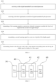
- FIG. 1 is a flow chart of a driving method of a display panel according to a first embodiment of the present disclosure.
- the driving method includes operations executed by the following blocks.
- the driving method in the embodiment is a method for driving a light-emitting unit of the display panel through a driving assembly, so that the light-emitting unit correspondingly displays a video signal transmitted by a processor to the driving assembly.
- the display panel includes a plurality of pixels arranged in an array, that is, the display panel correspondingly includes a plurality of rows of pixels.
- the driving assembly may transmit a corresponding driving signal to each pixel to display the video signal.
- the processor may refer to a central processing unit of the corresponding display device outside the display panel.
- a first scanning signal is transmitted to a current row of pixels in response to a first gray-scale value of each of the current row of pixels of the display panel corresponding to or for the video signal being greater than a preset gray-scale value.
- the driving assembly may analyze the video signal and determine a gray scale of each pixel of the display panel corresponding to or for the video signal.
- the driving assembly when the driving assembly determines that the first gray-scale value of the each of the current row of pixels of the display panel corresponding to or for a currently received video signal is greater than the preset gray-scale value, the driving assembly may transmit the first scanning signal to the current row of pixels.
- the current row of pixels refers to the pixel at a row which is being scanned at a current time point, and may be corresponding to any one row of pixels in the display panel.
- the preset gray-scale value may correspond to scattering times of a pulse width modulation (PWM) signal preset by the driving assembly.
- PWM pulse width modulation
- the preset gray-scale value may be any other reasonable value such as 32 or 64, which is not limited herein.
- a second scanning signal is transmitted to a next row of pixels of the display panel.
- the driving assembly continues to transmit the second scanning signal to the next row of pixels of the display panel.
- a data signal is transmitted to the display panel, and the display panel is driven to display the video signal.
- the driving assembly may correspondingly analyze a corresponding PWM signal of the data signal transmitted to each column of pixels, or directly receive the PWM signal correspondingly transmitted by the external processor.
- a gray scale 1 corresponds to a period of one GCLK
- a gray scale 2 corresponds to a period of two GCLKs
- a gray scale 3 corresponds to a period of three GCLKs, and so on sequentially. In this way, after the first gray-scale value is determined, the PWM signal corresponding to the data signal to be transmitted may be obtained.
- the driving assembly may correspondingly analyze the PWM signal and determine a transmission mode of a high level state and a low level state of the data signal according to the PWM signal, transmit the data signal to the display panel, and drive the display panel to display the video signal.
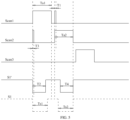
- FIG. 2 is a corresponding signal waveform view of the driving method of the display panel shown in FIG. 1 in an application scenario. Scan1 shown in FIG.
- Scan2 corresponds to a waveform view of the second scanning signal
- Scan3 corresponds to a waveform view of a third scanning signal transmitted by the driving device to a further next row of pixels (i.e., a next row of the next row of pixels).
- S1 is a waveform view of a data signal transmitted to the display panel corresponding to the driving device according to a conventional embodiment
- S1' is a waveform view of a data signal transmitted to the display panel based on the first gray-scale value according to an embodiment of the present disclosure.
- the first scanning signal is a high level in a current-row scanning period (i.e., a scanning period of the current row) Ta1.
- the first scanning signal has a high level with a first time width T1 in a next-row scanning period (i.e., a scanning period of the next row) Ta2.
- the second scanning signal is a high level in the next-row scanning period Ta2.
- the first time width (i.e., duration width) T1 may be a time width corresponding to or for a gray-scale value of 1, that is, the first time width T1 corresponds to a pulse width of a global clock. In other embodiments, the first time width T1 may also be any reasonable time width less than a pulse width Ts2 of the PWM signal, which is not limited herein.
- the PWM signal Ts1 corresponding to the first gray-scale value is divided into two parts, so as to light up a current row of pixels in the current-row scanning period Ta1 and a current row of pixels in the next-row scanning period Ta2. In this way, a refresh rate corresponding to a current row of pixels may be doubled, and thus the purpose of increasing the refresh rate may be achieved.
- a gray-scale modulation pulse width corresponding to the data signal is divided into two parts, and a corresponding pixel corresponding to the current-row scanning period (i.e., the current row of pixels) and a corresponding pixel corresponding to the next-row scanning period (i.e., the next row of pixels) are lighted up, respectively.
- the high gray scale may be effectively improved, that is, the high gray scale is larger than the refresh rate in the display scenario with the preset gray-scale value, thereby effectively improving the high gray scale of the display image quality.
- the driving method further includes: analyzing the video signal and obtaining the first gray-scale value of the each of the current row of pixels of the display panel corresponding to the video signal.
- the driving assembly of the display panel may obtain the first gray-scale value of the each of the current row of pixels by analyzing the video signal.
- FIG. 3 is a flow chart of a block S14 shown in FIG. 1 corresponding to an embodiment.
- the above-mentioned block S14 may further include operations executed by the following blocks.
- a PWM signal is generated based on the first gray-scale value.
- the driving assembly may correspondingly analyze a PWM signal corresponding to or for the data signal transmitted to the each column of pixels.
- the gray scale 1 corresponds to the period of one GCLK
- the gray scale 2 corresponds to the period of two GCLKs
- the gray scale 3 corresponds to the period of three GCLKs, and so on sequentially. In this way, after the first gray-scale value is determined, the PWM signal corresponding to or for the data signal to be transmitted may be obtained.
- a data signal is transmitted to the display panel according to or by using the PWM signal, and the display panel is driven to display the video signal.
- the transmission mode of the high level state and a low level state of the data signal is determined according to the PWM signal. Based on the transmission mode, the data signal is transmitted to the display panel, such that the data signal has a corresponding high level state and a corresponding low level state to drive the display panel to display the video signal.
- the above-mentioned block S141 may also be replaced by: receiving the PWM signal transmitted by the processor.
- a processing program configured to analyze the PWM signal from the first gray-scale value is integrated on the processor, such that the amount of calculating and processing data of the driving assembly may be effectively reduced, thereby improving the processing efficiency of the display panel.
- FIG. 4 is a flow chart of the driving method of the display panel according to a second embodiment of the present disclosure.
- the driving method of the display panel according to the embodiment of the present disclosure is a flow chart of a detailed embodiment of the driving method of the display panel shown in FIG. 1 , and includes operations executed by the following blocks.
- the video signal transmitted by the external processor is received.
- the first scanning signal is transmitted to the current row of pixels in response to the first gray-scale value of the each of the current row of pixels of the display panel corresponding to the video signal being greater than the preset gray-scale value.
- the block S21 and the block S22 are the same as the block S11 and the block S12 shown in FIG. 1 , respectively, which may refer to S11 and S12 and the relevant description above, and will not be repeated herein.
- the second scanning signal is transmitted to the next row of pixels in response to the second gray-scale value of the each of the next row of pixels corresponding to the video signal being greater than the preset gray-scale value.
- the driving assembly may transmit the second scanning signal to the next row of pixels.
- the second scanning signal may also have a high level with a corresponding pulse width corresponding to the current-row scanning period.
- a data signal is transmitted to the display panel, and the display panel is driven to display the video signal.
- the driving assembly may transmit the data signal to the display panel and drive the display panel to display the video signal.
- FIG. 5 is a corresponding signal waveform view of the driving method of the display panel shown in FIG. 4 in an application scenario. Scan1 shown in FIG.
- S1 is a waveform view of a data signal transmitted to the display panel corresponding to the driving device according to a conventional embodiment
- S1' is a waveform view of a data signal transmitted to the display panel based on the first gray-scale value according to an embodiment of the present disclosure.
- the second scanning signal further has a high level with a third time width T3 in the current-row scanning period Ta1, and the data signal has a low level with a fourth time width T4 in the next-row scanning period Ta2.
- the third time width T3 is less than the second time width T2.
- the first time width T1 is further less than the fourth time width T4.
- the case, in which the first gray-scale value is greater than the preset gray-scale value, the pulse width of the gray scale PWM signal corresponding to the first gray-scale value is Ts1, the second gray-scale value of the each of the next row of pixels of the display panel corresponding to the video signal is also greater than the preset gray-scale value, and the pulse width of the gray scale PWM signal corresponding to the second gray-scale value is Ts2, is taken to be as an example.
- FIG. 6 is a corresponding signal waveform view of the driving method of the display panel shown in FIG. 4 in another application scenario.
- the third time width T3 is less than the second time width T2.
- the driving method may further include: transmitting the third scanning signal to the further next row of pixels of the display panel.
- the pulse width of the gray scale PWM signal corresponding to the first gray scale is Ts1
- the second gray-scale value of the each of the next row of pixels of the display panel corresponding to the video signal is also greater than the preset gray-scale value
- the pulse width of the gray scale PWM signal corresponding to the second gray scale is Ts2.
- the third gray-scale value corresponding to the further next row of pixels of the display panel is less than the preset gray-scale value
- a pulse width of a gray scale PWM signal corresponding to the third gray scale is Ts3. As shown in FIG. 7, FIG.
- the second scanning signal has a high level with a fifth time width T5 in a further next-row scanning period Ta3.
- the third time width T3 is less than the second time width T2.
- FIG. 8 is a flow chart of the driving method of the display panel according to a third embodiment of the present disclosure.
- the driving method of the display panel according to the embodiment of the present disclosure is a flow chart of a detailed embodiment of the driving method of the display panel shown in FIG. 1 , and includes operations executed by the following blocks.
- the block S31 is the same as the block S11 shown in FIG. 1 , which may refer to the block S11 and the relevant description above, and will not be repeated herein.
- a first level signal and a second level signal transmitted by the processor are received.
- a driving control signal may also be served as a prerequisite to determine whether the first grayscale value of each of the current row of pixels of the display panel corresponding to the currently received video signal is greater than the preset gray-scale value via a logic level signal transmitted by the processor and received by the driving control signal. For example, when the first level signal and the second level signal received by the driving control signal are 1, it is determined that the first gray-scale value of the each of the current row of pixels of the display panel corresponding to the currently received video signal is greater than the preset gray-scale value.
- the first level signal and the second level signal received by the driving control signal are 0, it is determined that the first gray-scale value of the each of the current row of pixels of the display panel corresponding to the currently received video signal is not greater than, i.e., or less than or equal to, the preset gray-scale value.
- the first scanning signal is transmitted to the current row of pixels in response to neither the first level signal nor the second level signal being 0.
- the first gray-scale value of the each of the current row of pixels of the display panel corresponding to the currently received video signal is greater than the preset gray-scale value, and it is necessary to transmit the first scanning signal to the current row of pixels.
- the first scanning signal is a high level in the current-row scanning period Ta1, and has a high level with the first time width T1 in the next-row scanning period Ta2.
- the second scanning signal is a high level in the next-row scanning period Ta2.
- the first level signal and the second level signal may also correspondingly use the high level and the low level to replace judgment of logic 1 and logic 0.
- the first level signal and the second level signal may be converted into a digital signal 1 or a digital signal 0, so as to enable the driving assembly to make corresponding logical judgment based on the digital signal.
- the first level signal and the second level signal may also be correspondingly transmitted by the control unit of the driving assembly to a driving unit of the driving assembly, so that the driving unit may correspondingly transmit the first scanning signal, a subsequent second scanning signal, and the data signal, which is not limited herein.
- the second scanning signal is transmitted to the next row of pixels of the display panel.
- the data signal is transmitted to the display panel, and the display panel is driven to display the video signal.
- the block S34 and the block S35 are the same as the block S13 and the block S14 shown in FIG. 1 , respectively, which may refer to the blocks S13 and S14 and the relevant description above, and will not be repeated herein.
- a driving device of a display panel is further provided in some embodiments of the present disclosure.
- FGI. 9 is a structural schematic view of a driving device of a display panel according to a first embodiment of the present disclosure.
- a display panel 60 includes a plurality of pixels arranged in an array, and a driving device 40 includes a control unit 41 and a driving unit 42.
- the control unit 41 is coupled to an external processor 50 and configured to receive the video signal transmitted by the external processor 50.
- the control unit 41 is configured to generate a first control signal in response to the first gray-scale value of the each of the current row of pixels of the display panel 60 corresponding to the video signal being greater than the preset gray-scale value.
- the driving unit 42 is coupled to the control unit 41 and the external display panel 60, such that when receiving the first control signal and the first gray-scale value transmitted by the control unit 41, the driving unit 42 is configured to transmit the first scanning signal to the current row of pixels based on the first control signal and transmit the second scanning signal to the next row of pixels of the display panel 60.
- the control unit 41 may be configured to transmit the data signal to the display panel 60, and drive the display panel 60 to display the video signal.
- the first scanning signal is a high level in the current-row scanning period and has a high level with the first time width in the next-row scanning period.
- the second scanning signal is a high level in the next-row scanning period, and the data signal has a low level with the second time width in the current-row scanning period.
- a sum of the first time width and the second time width corresponds to the first gray-scale value.
- control unit 41 when the control unit 41 determines that the second gray-scale value of the each of the next row of pixels corresponding to the video signal is greater than the preset gray-scale value, the control unit 41 may further generate a second control signal correspondingly, so as to transmit the second control signal and the second gray-scale value to the driving unit 42. In this way, based on the second control signal, it may be possible to make the driving unit 42 transmit the first scanning signal to the current row of pixels, so as to transmit the second scanning signal to the next row of pixels. In addition, based on the first gray-scale value and the second gray-scale value, the driving unit 42 may transmit the data signal to the display panel 60 and drive the display panel 60 to display the video signal.
- the second scanning signal further has a high level with the third time width in the current-row scanning period, and the data signal has a low level with the fourth time width in the next-row scanning period.
- the third time width is less than the second time width, and the sum of the third time width plus the fourth time width corresponds to the second gray-scale value.
- the driving method when the driving unit 42 receives the first gray-scale value transmitted by the control unit 41, the driving method further includes: generating a PWM signal based on the first gray-scale value, and transmitting the data signal to the display panel according to the PWM signal.
- the first time width is a time width corresponding to or for a gray-scale value of 1.
- the driving device 40 provided in the embodiment may also implement other methods, such as the driving method of the display panel 60 according to any one of above-mentioned embodiments, according to the gray-scale value information of each row of pixels of the display panel 60 corresponding to the video signal.
- the driving method of the display panel 60 according to any one of above-mentioned embodiments, according to the gray-scale value information of each row of pixels of the display panel 60 corresponding to the video signal.
- FIG. 10 is a structural schematic view of the driving device of the display panel according to a second embodiment of the present disclosure.
- the control unit 71 of the driving device 70 further includes a timing controller 711 and a brightness detection unit 712 which are coupled to each other
- the driving unit 42 further includes a row driving unit 421 and a column driving unit 422 that are coupled to the timing controller 711.
- the brightness detection unit 712 is coupled to the processor, so as to receive the video signal transmitted by the processor.
- the brightness detection unit 712 is configured to transmit the first level signal to the timing controller 711 when the brightness detection unit 712 detects that the gray scale corresponding to the video signal is not 0.
- the timing controller 711 After receiving the first level signal, the timing controller 711 transmits the second level signal and the third level signal to the row driving unit 421 and the column driving unit 422, respectively.
- the row driving unit 421 transmits the first scanning signal to the current row of pixels of the display panel, transmits the second scanning signal to the next row of pixels of the display panel, and makes the column driving unit 422 transmit the data signal to the display panel.
- the first level signal is a level signal of logic 0 or a low level signal.
- the second level signal and the third level signal are level signals of logic 1 or high level signals.
- FIG. 11 is a structural schematic view of a display device according to an embodiment of the present disclosure.
- the display device 80 includes a display panel 81 and a driving device 82.
- the driving device 82 is coupled to the display panel 81, and is configured to drive the light-emitting unit of the display panel 81 to emit light.
- the driving device 82 is the driving device 40 or the driving device 70 according to any one of above-mentioned embodiments, which will not be repeated here.
- the first scanning signal when the video signal transmitted by the external processor is received, the first scanning signal may be transmitted to the current row of pixels in response to the first gray-scale value of the each of the current row of pixels of the display panel corresponding to the video signal being greater than the preset gray-scale value.
- the second scanning signal may be transmitted to the next row of pixels of the display panel, and based on the first gray-scale value, the data signal may be transmitted to the display panel, and the display panel is driven to display the video signal.
- the first scanning signal is the high level in the current-row scanning period and has the high level with the first time width in the next-row scanning period.
- the second scanning signal is the high level in the next-row scanning period
- the data signal has the low level with the second time width in the current-row scanning period
- the sum of the first time width and the second time width corresponds to the first gray-scale value.
- the gray-scale modulation pulse width corresponding to the data signal is divided into the two parts, and a corresponding pixel corresponding to the current-row scanning period and a corresponding pixel corresponding to the next-row scanning period are lighted up, respectively. Therefore, the high gray scale may be effectively improved, that is, the high gray scale is larger than the refresh rate in the display scenario with the preset gray-scale value, thereby effectively improving the high gray scale of the display image quality.
Landscapes
- Engineering & Computer Science (AREA)
- Physics & Mathematics (AREA)
- Computer Hardware Design (AREA)
- General Physics & Mathematics (AREA)
- Theoretical Computer Science (AREA)
- Control Of Indicators Other Than Cathode Ray Tubes (AREA)
- Liquid Crystal Display Device Control (AREA)
- Control Of El Displays (AREA)
Abstract
Description
- The present disclosure relates to the field of display panel technologies, and in particular to a driving method and a driving device of a display panel.
- As a pixel arrangement in a display panel develops in a direction of small spacing, a light emitting diode (LED) display screen has put forward a higher requirement for row driving, namely, from a simple p-type Metal-Oxide-Semiconductor Field-Effect Transistor (P-MOSFET) for achieving row switching to a multi-functional row driving with a higher integration and a stronger function. For example, when one of data signals for a controlling row, i.e., a data signal Row (n+1), is low, a voltage on a row line, namely, an anode voltage of a LED lamp located in the controlling row, may be pulled up. However, data Out (m) of a column tube, that is, a cathode voltage of the LED lamp may be displayed, and different brightness of the LED lamp may be correspondingly obtained based on a width of a waveform with an Out (m) of low voltage.
- The width of the waveform with the Out (m) of low voltage is controlled by a pulse width modulation (PWM) signal corresponding to a global clock (GCLK) signal. The PWM signal corresponds to a gray scale of a display frame. For example, one GCLK period represents a pulse width of a
gray scale 1, two GCLK periods represent a pulse width of a gray scale 2, and three GCLK periods represent a pulse width of a gray scale 3. That is, the pulse width of the gray scale 2 is twice that of thegray scale 1, and the pulse width of the gray scale 3 is three times that of thegray scale 1. For an architecture using the PWM for the gray scale, the gray scale is only related to the GCLK, and the number of GCLKs in one row is an upper limit of the gray scale. A refresh rate is defined as the number of times that the LED lamp is turned on/off in one second. For example, the LED lamp is turned on/off m times in one second, the pulse width appears m times, and the refresh rate is mHz. For a high gray scale, the Out (m) displayed by the PWM may be very wide, that is, the greater the brightness required, the wider the width of the PWM required. If a scattering function is added, the refresh rate will be multiplied. In addition, according to the analysis of an application scenario of a LED display screen, the high gray scale is usually applied widely. This is because most of LED display screens are outdoor large screens, a viewing distance of the outdoor large screen is much longer than that of a LED display screen in an indoor household, and it may be conducive to improve the display quality by increasing the refresh rate. - However, for the display with a high gray scale, for example, when a gray-scale value is greater than a scattering number, the refresh rate may be fixed. Therefore, it may be impossible to increase the refresh rate again, and thus it may restrict the display panel to continue to improve a display effect in the high gray scale.
- Some embodiments of the present disclosure provide a driving method and a driving device of a display panel, so as to solve a problem that the display panel in the related art cannot effectively increase a refresh rate when displaying in a high gray scale, resulting in restricting the display panel from improving a display effect in the high gray scale.
- In order to solve the above technical problem, a technical solution adopted by some embodiments of the present disclosure is to provide a driving method of a display panel. The display panel includes a plurality of pixels arranged in an array. The driving method includes: receiving a video signal transmitted by an external processor; transmitting a first scanning signal to a current row of pixels in response to a first gray-scale value of each of the current row of pixels of the display panel corresponding to the video signal being greater than a preset gray-scale value; transmitting a second scanning signal to a next row of pixels of the display panel; and transmitting, based on the first gray-scale value, a data signal to the display panel and driving the display panel to display the video signal. The first scanning signal is a high level in a current-row scanning period and has a high level with a first time width in a next-row scanning period, the second scanning signal is a high level in the next-row scanning period, the data signal has a low level with a second time width in the current-row scanning period, and a sum of the first time width and the second time width corresponds to the first gray-scale value.
- In some embodiments, the transmitting a second scanning signal to a next row of pixels of the display panel includes: transmitting the second scanning signal to the next row of pixels in response to a second gray-scale value of each of the next row of pixels corresponding to the video signal being greater than the preset gray-scale value; and the transmitting, based on the first gray-scale value, a data signal to the display panel and driving the display panel to display the video signal includes: transmitting, based on the first gray-scale value and the second gray-scale value, the data signal to the display panel and driving the display panel to display the video signal. The second scanning signal further has a high level with a third time width in the current-row scanning period, the data signal has a low level with a fourth time width in the next-row scanning period, the third time width is less than the second time width, and a sum of the third time width and the fourth time width corresponds to the second gray-scale value.
- In some embodiments, the first time width is less than the fourth time width.
- In some embodiments, the second time width corresponds to the first gray-scale value.
- In some embodiments, after the transmitting the second scanning signal to the next row of pixels in response to a second gray-scale value of each of the next row of pixels corresponding to the video signal being greater than the preset gray-scale value, and before the transmitting, based on the first gray-scale value and the second gray-scale value, the data signal to the display panel and driving the display panel to display the video signal, the driving method further includes: transmitting a third scanning signal to a further next row of pixels of the display panel; the second scanning signal has a high level with a fifth time width in a further next-row scanning period, and a sum of the third time width, the fourth time width, and the fifth time width corresponds to the second gray-scale value.
- In some embodiments, after the receiving a video signal transmitted by an external processor, and before the transmitting a first scanning signal to a current row of pixels in response to a first gray-scale value of each of the current row of pixels of the display panel corresponding to the video signal being greater than a preset gray-scale value, the driving method further includes: receiving a first level signal and a second level signal transmitted by the processor; the transmitting a first scanning signal to a current row of pixels in response to a first gray-scale value of each of the current row of pixels of the display panel corresponding to the video signal being greater than a preset gray-scale value, includes: transmitting the first scanning signal to the current row of pixels in response to neither the first level signal nor the second level signal being 0.
- In some embodiments, the transmitting the first scanning signal to the current row of pixels in response to neither the first level signal nor the second level signal being 0, includes: determining that neither a digital signal corresponding to the first level signal nor a digital signal corresponding to the second level signal is 0, and transmitting the first scanning signal to the current row of pixels, in response to neither the first level signal nor the second level signal being a high level.
- In some embodiments, after the receiving a video signal transmitted by an external processor, and before the transmitting a first scanning signal to a current row of pixels in response to a first gray-scale value of each of the current row of pixels of the display panel corresponding to the video signal being greater than a preset gray-scale value, the driving method further includes: analyzing the video signal and obtaining the first gray-scale value of each of the current row of pixels of the display panel corresponding to the video signal.
- In some embodiments, the transmitting, based on the first gray-scale value, a data signal to the display panel and driving the display panel to display the video signal, includes: generating a pulse width modulation signal based on the first gray-scale value; transmitting the data signal to the display panel according to the PWM signal and driving the display panel to display the video signal.
- In some embodiments, the transmitting, based on the first gray-scale value, a data signal to the display panel and driving the display panel to display the video signal, includes: receiving a pulse width modulation signal transmitted by the processor; and transmitting the data signal to the display panel according to the PWM signal and driving the display panel to display the video signal.
- In some embodiments, the transmitting the data signal to the display panel according to the PWM signal and driving the display panel to display the video signal, includes: determining a transmission mode of a high level state and a low level state of the data signal according to the PWM signal, transmitting the data signal to the display panel based on the transmission mode, and driving the display panel to display the video signal.
- In some embodiments, the first time width is less than a pulse width of the PWM signal.
- In some embodiments, the first time width is a time width for a gray-scale value of 1.
- In some embodiments, the preset gray-scale value is 32 or 64.
- In order to solve the above technical problem, another technical solution adopted by some embodiments of the present disclosure is to provide a driving device of a display panel. The display panel includes a plurality of pixels arranged in an array. The driving device includes: a control unit, coupled to an external processor, and configured to receive a video signal transmitted by the external processor and generate a first control signal in response to a first gray-scale value of each of a current row of pixels of the display panel corresponding to the video signal being greater than a preset gray-scale value; and a driving unit, coupled to the control unit and an external display panel, and configured to receive the first control signal and the first gray-scale value transmitted by the control unit, transmit, based on the first control signal, a first scanning signal to the current row of pixels, transmit the second scanning signal to a next row of pixels of the display panel, and transmit, based on the first gray-scale value, a data signal to the display panel and drive the display panel to display the video signal; the first scanning signal is a high level in a current-row scanning period and has a high level with a first time width in a next-row scanning period, the second scanning signal is a high level in the next-row scanning period, the data signal has a low level with a second time width in the current-row scanning period, and a sum of the first time width and the second time width corresponds to the first gray-scale value.
- In some embodiments, the control unit is configured to generate a second control signal in response to the control unit determining that a second gray-scale value of each of the next row of pixels corresponding to the video signal is greater than the preset gray-scale value, and transmit the second control signal and the second gray-scale value to the driving unit; based on the second control signal, the driving unit is configured to transmit the first scanning signal to the current row of pixels, and transmit a second scanning signal to the next row of pixels; and based on the first gray-scale value and the second gray-scale value, the driving unit is configured to transmit the data signal to the display panel and drive the display panel to display the video signal; the second scanning signal further has a high level with a third time width in the current-row scanning period, the data signal has a low level with a fourth time width in the next-row scanning period, the third time width is less than the second time width, and a sum of the third time width and the fourth time width corresponds to the second gray-scale value.
- In some embodiments, in response to the driving unit receiving the first gray-scale value transmitted by the control unit, the driving unit is configured to generate a pulse width modulation signal based on the first gray-scale value, and transmit the data signal to the display panel according to the PWM signal.
- In some embodiments, the control unit further includes a timing controller and a brightness detection unit coupled to each other, and the driving unit further includes a row driving unit coupled to the timing controller and a column driving unit coupled to the timing controller; the brightness detection unit is coupled to the processor, and configured to receive the video signal transmitted by the processor, and transmit a first level signal to the timing controller in response to the brightness detection unit detecting that the gray scale corresponding to the video signal is not 0;after receiving the first level signal, the timing controller is configured to transmit a second level signal and a third level signal to the row driving unit and the column driving unit, respectively, and the row driving unit is configured to transmit the first scanning signal to the current row of pixels of the display panel, transmit the second scanning signal to the next row of pixels of the display panel, and drive the column driving unit to transmit the data signal to the display panel.
- In some embodiments, the first time width is a time width for a gray-scale value of 1.
- In order to solve the above technical problem, yet another technical solution adopted by some embodiments of the present disclosure is to provide a display device. The display device includes a display panel and the driving device according to any one of above-mentioned embodiments. The driving device is coupled to the display panel and configured to drive a light-emitting unit of the display panel to emit light.
- Different from the related art, the following technical effects of some embodiments of the present disclosure may be achieved. In the driving method provided in some embodiments of the present disclosure, when the video signal transmitted by the external processor is received, the first scanning signal may be transmitted to the current row of pixels in response to the first gray-scale value of the each of the current row of pixels of the display panel corresponding to the video signal being greater than the preset gray-scale value, and the second scanning signal may be transmitted to the next row of pixels of the display panel. Based on the first gray-scale value, the data signal may be transmitted to the display panel, and the display panel is driven to display the video signal. The first scanning signal is the high level in the current-row scanning period and has the high level with the first time width in the next-row scanning period. The second scanning signal is the high level in the next-row scanning period, the data signal has the low level with the second time width in the current-row scanning period, and the sum of the first time width and the second time width corresponds to the first gray-scale value. In this way, a gray-scale modulation pulse width corresponding to the data signal is divided into two parts, and a corresponding pixel corresponding to the current-row scanning period and a corresponding pixel corresponding to the next-row scanning period are lighted up, respectively. Therefore, the high gray scale may be effectively improved, that is, the high gray scale is larger than the refresh rate in the display scenario with the preset gray-scale value, thereby effectively improving the high gray scale of the display image quality.
- In order to illustrate the technical solutions more clearly in the embodiments of the present disclosure, the following will be briefly described in the description of the embodiments required to use the attached drawings. It is obvious that the following description of the attached drawings are only some of the embodiments of the present disclosure, and those skilled in the art, without creative work, can also obtain other attached drawings based on these drawings.
-
FIG. 1 is a flow chart of a driving method of a display panel according to a first embodiment of the present disclosure. -
FIG. 2 is a corresponding signal waveform view of the driving method of the display panel shown inFIG. 1 in an application scenario. -
FIG. 3 is a flow chart of a block S14 shown inFIG. 1 corresponding to an embodiment. -
FIG. 4 is a flow chart of the driving method of the display panel according to a second embodiment of the present disclosure. -
FIG. 5 is a corresponding signal waveform view of the driving method of the display panel shown inFIG. 4 in an application scenario. -
FIG. 6 is a corresponding signal waveform view of the driving method of the display panel shown inFIG. 4 in another application scenario. -
FIG. 7 is a corresponding signal waveform view of the driving method of the display panel shown inFIG. 1 in yet another application scenario. -
FIG. 8 is a flow chart of the driving method of the display panel according to a third embodiment of the present disclosure. -
FIG. 9 is a structural schematic view of a driving device of a display panel according to a first embodiment of the present disclosure. -
FIG. 10 is a structural schematic view of the driving device of the display panel according to a second embodiment of the present disclosure. -
FIG. 11 is a structural schematic view of a display device according to an embodiment of the present disclosure. - Reference numerals in drawings:
40/70/82, driving device; 41/71, control unit; 42/72, driving unit; 50, external processor; 60/81, display panel; 711, timing controller; 712, brightness detection unit; 721, row driving unit; 722, column driving unit; 80, display device. - In order to illustrate the technical problems solved, the technical solutions adopted, and the technical effects achieved by some embodiments of the present disclosure more clearly, the technical solutions in the embodiments of the present disclosure will be further described in detail below in conjunction with the accompanying drawings.
- The term "embodiments" may indicate that a particular feature, a structure or a property described in one embodiment may be included in at least one embodiment of the present disclosure. Presence of the term in various sections in the specification does not necessarily mean a same embodiment or a separate or an alternative embodiment that is mutually exclusive with other embodiments. It shall be understood, both explicitly and implicitly, by any ordinary skilled person in the art that the embodiments described herein may be combined with other embodiments.
- As shown in
FIG. 1, FIG. 1 is a flow chart of a driving method of a display panel according to a first embodiment of the present disclosure. In the embodiment, the driving method includes operations executed by the following blocks. - At block S11, a video signal transmitted by an external processor is received.
- It should be understood that, the driving method in the embodiment is a method for driving a light-emitting unit of the display panel through a driving assembly, so that the light-emitting unit correspondingly displays a video signal transmitted by a processor to the driving assembly.
- In some embodiments, the display panel includes a plurality of pixels arranged in an array, that is, the display panel correspondingly includes a plurality of rows of pixels. In response to the driving assembly receiving the video signal transmitted by the external processor, the driving assembly may transmit a corresponding driving signal to each pixel to display the video signal.
- It should be noted that the processor may refer to a central processing unit of the corresponding display device outside the display panel.
- At block S12, a first scanning signal is transmitted to a current row of pixels in response to a first gray-scale value of each of the current row of pixels of the display panel corresponding to or for the video signal being greater than a preset gray-scale value.
- It should be understood that, after the driving assembly receives the video signal transmitted by the processor, the driving assembly may analyze the video signal and determine a gray scale of each pixel of the display panel corresponding to or for the video signal.
- In some embodiments, when the driving assembly determines that the first gray-scale value of the each of the current row of pixels of the display panel corresponding to or for a currently received video signal is greater than the preset gray-scale value, the driving assembly may transmit the first scanning signal to the current row of pixels.
- It should be noted that, the current row of pixels refers to the pixel at a row which is being scanned at a current time point, and may be corresponding to any one row of pixels in the display panel.
- The preset gray-scale value may correspond to scattering times of a pulse width modulation (PWM) signal preset by the driving assembly. In some embodiments, the preset gray-scale value may be any other reasonable value such as 32 or 64, which is not limited herein.
- At block S13, a second scanning signal is transmitted to a next row of pixels of the display panel.
- In some embodiments, the driving assembly continues to transmit the second scanning signal to the next row of pixels of the display panel.
- At block S14, based on the first gray-scale value, a data signal is transmitted to the display panel, and the display panel is driven to display the video signal.
- It should be understood that, after the driving assembly determines the gray scale of each pixel of the display panel corresponding to the video signal, the driving assembly may correspondingly analyze a corresponding PWM signal of the data signal transmitted to each column of pixels, or directly receive the PWM signal correspondingly transmitted by the external processor. A
gray scale 1 corresponds to a period of one GCLK, a gray scale 2 corresponds to a period of two GCLKs, a gray scale 3 corresponds to a period of three GCLKs, and so on sequentially. In this way, after the first gray-scale value is determined, the PWM signal corresponding to the data signal to be transmitted may be obtained. - In some embodiments, after the driving assembly determines the first gray-scale value of the each of the current row of pixels, the driving assembly may correspondingly analyze the PWM signal and determine a transmission mode of a high level state and a low level state of the data signal according to the PWM signal, transmit the data signal to the display panel, and drive the display panel to display the video signal.
- To facilitate understanding, a case, in which the first gray-scale value is greater than the preset gray-scale value, a pulse width of a PWM signal corresponding to the first gray-scale value is Ts1, a second gray-scale value of each of the next row of pixels of the display panel corresponding to the video signal is less than the preset gray-scale value, and a pulse width of a PWM signal corresponding to the second gray-scale value is Ts2, is taken to be as an example. As shown in
FIG. 2, FIG. 2 is a corresponding signal waveform view of the driving method of the display panel shown inFIG. 1 in an application scenario. Scan1 shown inFIG. 2 corresponds to a waveform view of the first scanning signal, Scan2 corresponds to a waveform view of the second scanning signal, and Scan3 corresponds to a waveform view of a third scanning signal transmitted by the driving device to a further next row of pixels (i.e., a next row of the next row of pixels). S1 is a waveform view of a data signal transmitted to the display panel corresponding to the driving device according to a conventional embodiment, and S1' is a waveform view of a data signal transmitted to the display panel based on the first gray-scale value according to an embodiment of the present disclosure. - It can be seen that the first scanning signal is a high level in a current-row scanning period (i.e., a scanning period of the current row) Ta1. The first scanning signal has a high level with a first time width T1 in a next-row scanning period (i.e., a scanning period of the next row) Ta2. The second scanning signal is a high level in the next-row scanning period Ta2. The data signal has a low level with a second time width T2 in the current-row scanning period Ta1, and a sum of the first time width T1 and the second time width T2 corresponds to the first gray-scale value, that is, T1+T2=Ts1.
- In some embodiments, the first time width (i.e., duration width) T1 may be a time width corresponding to or for a gray-scale value of 1, that is, the first time width T1 corresponds to a pulse width of a global clock. In other embodiments, the first time width T1 may also be any reasonable time width less than a pulse width Ts2 of the PWM signal, which is not limited herein.
- The PWM signal Ts1 corresponding to the first gray-scale value is divided into two parts, so as to light up a current row of pixels in the current-row scanning period Ta1 and a current row of pixels in the next-row scanning period Ta2. In this way, a refresh rate corresponding to a current row of pixels may be doubled, and thus the purpose of increasing the refresh rate may be achieved.
- In the above-mentioned technical solution, a gray-scale modulation pulse width corresponding to the data signal is divided into two parts, and a corresponding pixel corresponding to the current-row scanning period (i.e., the current row of pixels) and a corresponding pixel corresponding to the next-row scanning period (i.e., the next row of pixels) are lighted up, respectively. In this way, the high gray scale may be effectively improved, that is, the high gray scale is larger than the refresh rate in the display scenario with the preset gray-scale value, thereby effectively improving the high gray scale of the display image quality.
- In some embodiments, after the above-mentioned block S11 and before the above-mentioned block S12, the driving method further includes: analyzing the video signal and obtaining the first gray-scale value of the each of the current row of pixels of the display panel corresponding to the video signal.
- It should be understood that, after obtaining the video signal, the driving assembly of the display panel may obtain the first gray-scale value of the each of the current row of pixels by analyzing the video signal.
- As shown in
FIG. 3, FIG. 3 is a flow chart of a block S14 shown inFIG. 1 corresponding to an embodiment. In an embodiment, the above-mentioned block S14 may further include operations executed by the following blocks. - At block S141, a PWM signal is generated based on the first gray-scale value.
- It should be understood that, after the driving assembly determines the gray scale of each pixel of the display panel corresponding to the video signal, the driving assembly may correspondingly analyze a PWM signal corresponding to or for the data signal transmitted to the each column of pixels.
- The
gray scale 1 corresponds to the period of one GCLK, the gray scale 2 corresponds to the period of two GCLKs, the gray scale 3 corresponds to the period of three GCLKs, and so on sequentially. In this way, after the first gray-scale value is determined, the PWM signal corresponding to or for the data signal to be transmitted may be obtained. - At block S142, a data signal is transmitted to the display panel according to or by using the PWM signal, and the display panel is driven to display the video signal.
- In some embodiments, the transmission mode of the high level state and a low level state of the data signal is determined according to the PWM signal. Based on the transmission mode, the data signal is transmitted to the display panel, such that the data signal has a corresponding high level state and a corresponding low level state to drive the display panel to display the video signal.
- In another embodiment, the above-mentioned block S141 may also be replaced by: receiving the PWM signal transmitted by the processor.
- It should be understood that, a processing program configured to analyze the PWM signal from the first gray-scale value is integrated on the processor, such that the amount of calculating and processing data of the driving assembly may be effectively reduced, thereby improving the processing efficiency of the display panel.
- As shown in
FIG. 4, FIG. 4 is a flow chart of the driving method of the display panel according to a second embodiment of the present disclosure. The driving method of the display panel according to the embodiment of the present disclosure is a flow chart of a detailed embodiment of the driving method of the display panel shown inFIG. 1 , and includes operations executed by the following blocks. - At block S21, the video signal transmitted by the external processor is received.
- At block S22, the first scanning signal is transmitted to the current row of pixels in response to the first gray-scale value of the each of the current row of pixels of the display panel corresponding to the video signal being greater than the preset gray-scale value.
- The block S21 and the block S22 are the same as the block S11 and the block S12 shown in
FIG. 1 , respectively, which may refer to S11 and S12 and the relevant description above, and will not be repeated herein. - At block S23, the second scanning signal is transmitted to the next row of pixels in response to the second gray-scale value of the each of the next row of pixels corresponding to the video signal being greater than the preset gray-scale value.
- It should be understood that, in a case that the driving assembly determines that the second gray-scale value of the each of the next row of pixels corresponding to the currently received video signal is also greater than the preset gray-scale value, the driving assembly may transmit the second scanning signal to the next row of pixels. At this time, the second scanning signal may also have a high level with a corresponding pulse width corresponding to the current-row scanning period.
- At block S24, based on the first gray-scale value and the second gray-scale value, a data signal is transmitted to the display panel, and the display panel is driven to display the video signal.
- In some embodiments, based on the first gray-scale value and the second gray-scale value, the driving assembly may transmit the data signal to the display panel and drive the display panel to display the video signal.
- To facilitate understanding, in the embodiment, the case, in which the first gray-scale value is greater than the preset gray-scale value, a pulse width of a gray scale PWM signal corresponding to the first gray-scale value is Ts1, the second gray-scale value of the each of the next row of pixels of the display panel corresponding to the video signal is also greater than the preset gray-scale value, and a pulse width of a gray scale PWM signal corresponding to the second gray-scale value is Ts2, is taken to be as an example. As shown in
FIG. 5, FIG. 5 is a corresponding signal waveform view of the driving method of the display panel shown inFIG. 4 in an application scenario. Scan1 shown inFIG. 5 corresponds to a waveform view of the first scanning signal, Scan2 corresponds to a waveform view of the second scanning signal, and Scan3 corresponds to a waveform view of the third scanning signal transmitted by the driving device to the further next row of pixels. S1 is a waveform view of a data signal transmitted to the display panel corresponding to the driving device according to a conventional embodiment, and S1' is a waveform view of a data signal transmitted to the display panel based on the first gray-scale value according to an embodiment of the present disclosure. - It can be seen that the second scanning signal further has a high level with a third time width T3 in the current-row scanning period Ta1, and the data signal has a low level with a fourth time width T4 in the next-row scanning period Ta2. The third time width T3 is less than the second time width T2. A sum of the third time width T3 and the fourth time width T4 corresponds to the second gray-scale value, that is, T3+T4=Ts2.
- In some embodiments, the first time width T1 is further less than the fourth time width T4.
- In some embodiments, the case, in which the first gray-scale value is greater than the preset gray-scale value, the pulse width of the gray scale PWM signal corresponding to the first gray-scale value is Ts1, the second gray-scale value of the each of the next row of pixels of the display panel corresponding to the video signal is also greater than the preset gray-scale value, and the pulse width of the gray scale PWM signal corresponding to the second gray-scale value is Ts2, is taken to be as an example. As shown in
FIG. 6, FIG. 6 is a corresponding signal waveform view of the driving method of the display panel shown inFIG. 4 in another application scenario. At this time, the sum of the third time width T3 and the fourth time width T4 corresponds to the second gray-scale value, that is, T3+T4=Ts2. - In addition, the second time width T2 corresponds to the first gray-scale value, namely, T2=Ts1. The third time width T3 is less than the second time width T2.
- In some embodiments, after the above-mentioned block S23 and before the above-mentioned block S24, the driving method may further include: transmitting the third scanning signal to the further next row of pixels of the display panel.
- It should be understood that, in an embodiment, when the first gray-scale value is greater than the preset gray-scale value, the pulse width of the gray scale PWM signal corresponding to the first gray scale is Ts1, the second gray-scale value of the each of the next row of pixels of the display panel corresponding to the video signal is also greater than the preset gray-scale value, and the pulse width of the gray scale PWM signal corresponding to the second gray scale is Ts2. In addition, the third gray-scale value corresponding to the further next row of pixels of the display panel is less than the preset gray-scale value, and a pulse width of a gray scale PWM signal corresponding to the third gray scale is Ts3. As shown in
FIG. 7, FIG. 7 is a corresponding signal waveform view of the driving method of the display panel shown inFIG. 1 in yet another application scenario. At this time, the second scanning signal has a high level with a fifth time width T5 in a further next-row scanning period Ta3. A sum of the third time width T3, the fourth time width T4, and the fifth time width T5 corresponds to the second gray-scale value, that is, T3+T4+T5=Ts2. - In addition, the sum of the first time width T1 and the second time width T2 corresponds to the first gray-scale value, that is, T1+T2=Ts1. The third time width T3 is less than the second time width T2.
- As shown in
FIG. 8, FIG. 8 is a flow chart of the driving method of the display panel according to a third embodiment of the present disclosure. The driving method of the display panel according to the embodiment of the present disclosure is a flow chart of a detailed embodiment of the driving method of the display panel shown inFIG. 1 , and includes operations executed by the following blocks. - At block S31, the video signal transmitted by the external processor is received.
- The block S31 is the same as the block S11 shown in
FIG. 1 , which may refer to the block S11 and the relevant description above, and will not be repeated herein. - At block S32, a first level signal and a second level signal transmitted by the processor are received.
- It should be understood that, a driving control signal may also be served as a prerequisite to determine whether the first grayscale value of each of the current row of pixels of the display panel corresponding to the currently received video signal is greater than the preset gray-scale value via a logic level signal transmitted by the processor and received by the driving control signal. For example, when the first level signal and the second level signal received by the driving control signal are 1, it is determined that the first gray-scale value of the each of the current row of pixels of the display panel corresponding to the currently received video signal is greater than the preset gray-scale value. When the first level signal and the second level signal received by the driving control signal are 0, it is determined that the first gray-scale value of the each of the current row of pixels of the display panel corresponding to the currently received video signal is not greater than, i.e., or less than or equal to, the preset gray-scale value.
- At block S33, the first scanning signal is transmitted to the current row of pixels in response to neither the first level signal nor the second level signal being 0.
- In some embodiments, based on a determination that neither the first level signal nor the second level signal is 0, it is determined that the first gray-scale value of the each of the current row of pixels of the display panel corresponding to the currently received video signal is greater than the preset gray-scale value, and it is necessary to transmit the first scanning signal to the current row of pixels.
- In addition, the first scanning signal is a high level in the current-row scanning period Ta1, and has a high level with the first time width T1 in the next-row scanning period Ta2. The second scanning signal is a high level in the next-row scanning period Ta2. The data signal has a low level with the second time width T2 in the current-row scanning period Ta1, and the sum of the first time width T1 and the second time width T2 corresponds to the first gray-scale value, that is, T1+T2=Ts1.
- In other embodiments, the first level signal and the second level signal may also correspondingly use the high level and the low level to replace judgment of
logic 1 andlogic 0. In some embodiments, the first level signal and the second level signal may be converted into adigital signal 1 or adigital signal 0, so as to enable the driving assembly to make corresponding logical judgment based on the digital signal. In addition, the first level signal and the second level signal may also be correspondingly transmitted by the control unit of the driving assembly to a driving unit of the driving assembly, so that the driving unit may correspondingly transmit the first scanning signal, a subsequent second scanning signal, and the data signal, which is not limited herein. - At block S34, the second scanning signal is transmitted to the next row of pixels of the display panel.
- At block S35, based on the first gray-scale value, the data signal is transmitted to the display panel, and the display panel is driven to display the video signal.
- The block S34 and the block S35 are the same as the block S13 and the block S14 shown in
FIG. 1 , respectively, which may refer to the blocks S13 and S14 and the relevant description above, and will not be repeated herein. - A driving device of a display panel is further provided in some embodiments of the present disclosure. As shown in
FIG. 9 , FGI. 9 is a structural schematic view of a driving device of a display panel according to a first embodiment of the present disclosure. In the embodiment, adisplay panel 60 includes a plurality of pixels arranged in an array, and adriving device 40 includes acontrol unit 41 and a drivingunit 42. - The
control unit 41 is coupled to anexternal processor 50 and configured to receive the video signal transmitted by theexternal processor 50. Thecontrol unit 41 is configured to generate a first control signal in response to the first gray-scale value of the each of the current row of pixels of thedisplay panel 60 corresponding to the video signal being greater than the preset gray-scale value. - In some embodiments, the driving
unit 42 is coupled to thecontrol unit 41 and theexternal display panel 60, such that when receiving the first control signal and the first gray-scale value transmitted by thecontrol unit 41, the drivingunit 42 is configured to transmit the first scanning signal to the current row of pixels based on the first control signal and transmit the second scanning signal to the next row of pixels of thedisplay panel 60. In addition, based on the first gray-scale value, thecontrol unit 41 may be configured to transmit the data signal to thedisplay panel 60, and drive thedisplay panel 60 to display the video signal. - The first scanning signal is a high level in the current-row scanning period and has a high level with the first time width in the next-row scanning period. The second scanning signal is a high level in the next-row scanning period, and the data signal has a low level with the second time width in the current-row scanning period. A sum of the first time width and the second time width corresponds to the first gray-scale value.
- In an embodiment, when the
control unit 41 determines that the second gray-scale value of the each of the next row of pixels corresponding to the video signal is greater than the preset gray-scale value, thecontrol unit 41 may further generate a second control signal correspondingly, so as to transmit the second control signal and the second gray-scale value to the drivingunit 42. In this way, based on the second control signal, it may be possible to make the drivingunit 42 transmit the first scanning signal to the current row of pixels, so as to transmit the second scanning signal to the next row of pixels. In addition, based on the first gray-scale value and the second gray-scale value, the drivingunit 42 may transmit the data signal to thedisplay panel 60 and drive thedisplay panel 60 to display the video signal. - The second scanning signal further has a high level with the third time width in the current-row scanning period, and the data signal has a low level with the fourth time width in the next-row scanning period. The third time width is less than the second time width, and the sum of the third time width plus the fourth time width corresponds to the second gray-scale value.
- In an embodiment, when the driving
unit 42 receives the first gray-scale value transmitted by thecontrol unit 41, the driving method further includes: generating a PWM signal based on the first gray-scale value, and transmitting the data signal to the display panel according to the PWM signal. - In some embodiments, the first time width is a time width corresponding to or for a gray-scale value of 1.
- It should be understood that, the driving
device 40 provided in the embodiment may also implement other methods, such as the driving method of thedisplay panel 60 according to any one of above-mentioned embodiments, according to the gray-scale value information of each row of pixels of thedisplay panel 60 corresponding to the video signal. For details, please refer toFIG. 1 to FIG. 8 and the relevant description above, which will not be repeated herein. - As further shown in
FIG. 10, FIG. 10 is a structural schematic view of the driving device of the display panel according to a second embodiment of the present disclosure. A difference between the driving device of the display panel provided in the second embodiment and the driving device of the display panel provided in the first embodiments shown inFIG. 9 is that, thecontrol unit 71 of the drivingdevice 70 further includes atiming controller 711 and abrightness detection unit 712 which are coupled to each other, and the drivingunit 42 further includes a row driving unit 421 and a column driving unit 422 that are coupled to thetiming controller 711. - The
brightness detection unit 712 is coupled to the processor, so as to receive the video signal transmitted by the processor. In addition, thebrightness detection unit 712 is configured to transmit the first level signal to thetiming controller 711 when thebrightness detection unit 712 detects that the gray scale corresponding to the video signal is not 0. After receiving the first level signal, thetiming controller 711 transmits the second level signal and the third level signal to the row driving unit 421 and the column driving unit 422, respectively. In this way, the row driving unit 421 transmits the first scanning signal to the current row of pixels of the display panel, transmits the second scanning signal to the next row of pixels of the display panel, and makes the column driving unit 422 transmit the data signal to the display panel. - It should be noted that, in the embodiment, the first level signal is a level signal of
logic 0 or a low level signal. The second level signal and the third level signal are level signals oflogic 1 or high level signals. - As shown in
FIG. 11, FIG. 11 is a structural schematic view of a display device according to an embodiment of the present disclosure. - In the embodiment, the
display device 80 includes adisplay panel 81 and adriving device 82. The drivingdevice 82 is coupled to thedisplay panel 81, and is configured to drive the light-emitting unit of thedisplay panel 81 to emit light. - It should be noted that, the driving
device 82 is the drivingdevice 40 or the drivingdevice 70 according to any one of above-mentioned embodiments, which will not be repeated here. - Different from the related art, the following technical effects of some embodiments of the present disclosure may be achieved. In the driving method provided in some embodiments of the present disclosure, when the video signal transmitted by the external processor is received, the first scanning signal may be transmitted to the current row of pixels in response to the first gray-scale value of the each of the current row of pixels of the display panel corresponding to the video signal being greater than the preset gray-scale value. In addition, the second scanning signal may be transmitted to the next row of pixels of the display panel, and based on the first gray-scale value, the data signal may be transmitted to the display panel, and the display panel is driven to display the video signal. The first scanning signal is the high level in the current-row scanning period and has the high level with the first time width in the next-row scanning period. The second scanning signal is the high level in the next-row scanning period, the data signal has the low level with the second time width in the current-row scanning period, and the sum of the first time width and the second time width corresponds to the first gray-scale value. In this way, the gray-scale modulation pulse width corresponding to the data signal is divided into the two parts, and a corresponding pixel corresponding to the current-row scanning period and a corresponding pixel corresponding to the next-row scanning period are lighted up, respectively. Therefore, the high gray scale may be effectively improved, that is, the high gray scale is larger than the refresh rate in the display scenario with the preset gray-scale value, thereby effectively improving the high gray scale of the display image quality.
- The above description shows only embodiments of the present disclosure and does not limit the scope of the present disclosure. Any equivalent structure or equivalent process transformation performed based on the description and the accompanying drawings of the present disclosure, applied directly or indirectly in other related fields, shall be equally covered by the scope of the present disclosure.
Claims (20)
- A driving method of a display panel, the display panel comprising a plurality of pixels arranged in an array, and the driving method comprising:receiving a video signal transmitted by an external processor;transmitting a first scanning signal to a current row of pixels in response to a first gray-scale value of each of the current row of pixels of the display panel corresponding to the video signal being greater than a preset gray-scale value;transmitting a second scanning signal to a next row of pixels of the display panel; andtransmitting, based on the first gray-scale value, a data signal to the display panel and driving the display panel to display the video signal;wherein the first scanning signal is a high level in a current-row scanning period and has a high level with a first time width in a next-row scanning period, the second scanning signal is a high level in the next-row scanning period, the data signal has a low level with a second time width in the current-row scanning period, and a sum of the first time width and the second time width corresponds to the first gray-scale value.
- The driving method as claimed in claim 1, wherein the transmitting a second scanning signal to a next row of pixels of the display panel comprises:transmitting the second scanning signal to the next row of pixels in response to a second gray-scale value of each of the next row of pixels corresponding to the video signal being greater than the preset gray-scale value; andwherein the transmitting, based on the first gray-scale value, a data signal to the display panel and driving the display panel to display the video signal comprises:transmitting, based on the first gray-scale value and the second gray-scale value, the data signal to the display panel and driving the display panel to display the video signal;wherein the second scanning signal further has a high level with a third time width in the current-row scanning period, the data signal has a low level with a fourth time width in the next-row scanning period, the third time width is less than the second time width, and a sum of the third time width and the fourth time width corresponds to the second gray-scale value.
- The driving method as claimed in claim 2, wherein the first time width is less than the fourth time width.
- The driving method as claimed in claim 2, wherein the second time width corresponds to the first gray-scale value.
- The driving method as claimed in claim 2, wherein after the transmitting the second scanning signal to the next row of pixels in response to a second gray-scale value of each of the next row of pixels corresponding to the video signal being greater than the preset gray-scale value, and before the transmitting, based on the first gray-scale value and the second gray-scale value, the data signal to the display panel and driving the display panel to display the video signal, the driving method further comprises:transmitting a third scanning signal to a further next row of pixels of the display panel;wherein the second scanning signal has a high level with a fifth time width in a further next-row scanning period, and a sum of the third time width, the fourth time width, and the fifth time width corresponds to the second gray-scale value.
- The driving method as claimed in claim 1, wherein after the receiving a video signal transmitted by an external processor, and before the transmitting a first scanning signal to a current row of pixels in response to a first gray-scale value of each of the current row of pixels of the display panel corresponding to the video signal being greater than a preset gray-scale value, the driving method further comprises:receiving a first level signal and a second level signal transmitted by the processor;the transmitting a first scanning signal to a current row of pixels in response to a first gray-scale value of each of the current row of pixels of the display panel corresponding to the video signal being greater than a preset gray-scale value, comprises:
transmitting the first scanning signal to the current row of pixels in response to neither the first level signal nor the second level signal being 0. - The driving method as claimed in claim 1, wherein the transmitting the first scanning signal to the current row of pixels in response to neither the first level signal nor the second level signal being 0, comprises:
determining that neither a digital signal corresponding to the first level signal nor a digital signal corresponding to the second level signal is 0, and transmitting the first scanning signal to the current row of pixels, in response to neither the first level signal nor the second level signal being a high level. - The driving method as claimed in claim 1, wherein after the receiving a video signal transmitted by an external processor, and before the transmitting a first scanning signal to a current row of pixels in response to a first gray-scale value of each of the current row of pixels of the display panel corresponding to the video signal being greater than a preset gray-scale value, the driving method further comprises:
analyzing the video signal and obtaining the first gray-scale value of each of the current row of pixels of the display panel corresponding to the video signal. - The driving method as claimed in claim 1, wherein the transmitting, based on the first gray-scale value, a data signal to the display panel and driving the display panel to display the video signal, comprises:generating a pulse width modulation signal based on the first gray-scale value;transmitting the data signal to the display panel according to the PWM signal and driving the display panel to display the video signal.
- The driving method as claimed in claim 1, wherein the transmitting, based on the first gray-scale value, a data signal to the display panel and driving the display panel to display the video signal, comprises:receiving a pulse width modulation signal transmitted by the processor; andtransmitting the data signal to the display panel according to the PWM signal and driving the display panel to display the video signal.
- The driving method as claimed in claim 9 or 10, wherein the transmitting the data signal to the display panel according to the PWM signal and driving the display panel to display the video signal, comprises:
determining a transmission mode of a high level state and a low level state of the data signal according to the PWM signal, transmitting the data signal to the display panel based on the transmission mode, and driving the display panel to display the video signal. - The driving method as claimed in claim 10, wherein the first time width is less than a pulse width of the PWM signal.
- The driving method according to any one of claims 1-10, wherein the first time width is a time width for a gray-scale value of 1.
- The driving method according to any one of claims 1-10, wherein the preset gray-scale value is 32 or 64.
- A driving device of a display panel, the display panel comprising a plurality of pixels arranged in an array, and the driving device comprising:a control unit, coupled to an external processor, and configured to receive a video signal transmitted by the external processor and generate a first control signal in response to a first gray-scale value of each of a current row of pixels of the display panel corresponding to the video signal being greater than a preset gray-scale value; anda driving unit, coupled to the control unit and an external display panel, and configured to receive the first control signal and the first gray-scale value transmitted by the control unit, transmit, based on the first control signal, a first scanning signal to the current row of pixels, transmit the second scanning signal to a next row of pixels of the display panel, and transmit, based on the first gray-scale value, a data signal to the display panel and drive the display panel to display the video signal;wherein the first scanning signal is a high level in a current-row scanning period and has a high level with a first time width in a next-row scanning period, the second scanning signal is a high level in the next-row scanning period, the data signal has a low level with a second time width in the current-row scanning period, and a sum of the first time width and the second time width corresponds to the first gray-scale value.
- The driving device as claimed in claim 15, whereinthe control unit is configured to generate a second control signal in response to the control unit determining that a second gray-scale value of each of the next row of pixels corresponding to the video signal is greater than the preset gray-scale value, and transmit the second control signal and the second gray-scale value to the driving unit;based on the second control signal, the driving unit is configured to transmit the first scanning signal to the current row of pixels, and transmit a second scanning signal to the next row of pixels; andbased on the first gray-scale value and the second gray-scale value, the driving unit is configured to transmit the data signal to the display panel and drive the display panel to display the video signal;wherein the second scanning signal further has a high level with a third time width in the current-row scanning period, the data signal has a low level with a fourth time width in the next-row scanning period, the third time width is less than the second time width, and a sum of the third time width and the fourth time width corresponds to the second gray-scale value.
- The driving device as claimed in claim 15, wherein in response to the driving unit receiving the first gray-scale value transmitted by the control unit, the driving unit is configured to generate a pulse width modulation signal based on the first gray-scale value, and transmit the data signal to the display panel according to the PWM signal.
- The driving device as claimed in claim 15, whereinthe control unit further comprises a timing controller and a brightness detection unit coupled to each other, and the driving unit further comprises a row driving unit coupled to the timing controller and a column driving unit coupled to the timing controller;the brightness detection unit is coupled to the processor, and configured to receive the video signal transmitted by the processor, and transmit a first level signal to the timing controller in response to the brightness detection unit detecting that the gray scale corresponding to the video signal is not 0;after receiving the first level signal, the timing controller is configured to transmit a second level signal and a third level signal to the row driving unit and the column driving unit, respectively, and the row driving unit is configured to transmit the first scanning signal to the current row of pixels of the display panel, transmit the second scanning signal to the next row of pixels of the display panel, and drive the column driving unit to transmit the data signal to the display panel.
- The driving device as claimed in any one of claims 15-18, wherein the first time width is a time width for a gray-scale value of 1.
- A display device, comprising:
a display panel and the driving device as claimed in any one of claims 15-18, wherein the driving device is coupled to the display panel and configured to drive a light-emitting unit of the display panel to emit light.
Applications Claiming Priority (2)
| Application Number | Priority Date | Filing Date | Title |
|---|---|---|---|
| CN202210886690.XA CN115083339B (en) | 2022-07-26 | 2022-07-26 | Driving method and driving device of display panel |
| PCT/CN2022/143040 WO2024021518A1 (en) | 2022-07-26 | 2022-12-28 | Driving method and driving apparatus for display panel |
Publications (2)
| Publication Number | Publication Date |
|---|---|
| EP4564339A1 true EP4564339A1 (en) | 2025-06-04 |
| EP4564339A4 EP4564339A4 (en) | 2025-08-20 |
Family
ID=83241991
Family Applications (1)
| Application Number | Title | Priority Date | Filing Date |
|---|---|---|---|
| EP22952947.4A Pending EP4564339A4 (en) | 2022-07-26 | 2022-12-28 | DRIVING METHOD AND DRIVING APPARATUS FOR DISPLAY PANEL |
Country Status (6)
| Country | Link |
|---|---|
| US (1) | US12266295B2 (en) |
| EP (1) | EP4564339A4 (en) |
| JP (1) | JP7776664B2 (en) |
| KR (1) | KR102832906B1 (en) |
| CN (1) | CN115083339B (en) |
| WO (1) | WO2024021518A1 (en) |
Families Citing this family (1)
| Publication number | Priority date | Publication date | Assignee | Title |
|---|---|---|---|---|
| CN115083339B (en) * | 2022-07-26 | 2023-01-03 | 惠科股份有限公司 | Driving method and driving device of display panel |
Family Cites Families (29)
| Publication number | Priority date | Publication date | Assignee | Title |
|---|---|---|---|---|
| JP2003066922A (en) * | 2001-08-28 | 2003-03-05 | Seiko Epson Corp | Electro-optical devices and electronic equipment |
| EP1471494A1 (en) * | 2003-04-24 | 2004-10-27 | Barco N.V. | Organic light-emitting diode drive circuit for a display application |
| KR101166819B1 (en) * | 2005-06-30 | 2012-07-19 | 엘지디스플레이 주식회사 | A shift register |
| JP5256552B2 (en) * | 2006-07-10 | 2013-08-07 | Nltテクノロジー株式会社 | Liquid crystal display device, drive control circuit used for the liquid crystal display device, and drive method |
| JP5510859B2 (en) * | 2007-03-30 | 2014-06-04 | Nltテクノロジー株式会社 | Backlight device and liquid crystal display device |
| US8786542B2 (en) * | 2008-02-14 | 2014-07-22 | Sharp Kabushiki Kaisha | Display device including first and second scanning signal line groups |
| CN101673513B (en) * | 2009-10-30 | 2014-04-09 | 深圳市流明电子有限公司 | Control method |
| JP2011227374A (en) * | 2010-04-22 | 2011-11-10 | Funai Electric Co Ltd | Display device |
| JP6070918B2 (en) * | 2011-12-26 | 2017-02-01 | 日亜化学工業株式会社 | Display device lighting control method and display device |
| US10127858B1 (en) * | 2014-06-01 | 2018-11-13 | Bo Zhou | Display systems and methods for three-dimensional and other imaging applications |
| CN106710539B (en) * | 2015-11-12 | 2020-06-02 | 小米科技有限责任公司 | Liquid crystal display method and device |
| CN110383161A (en) * | 2017-01-16 | 2019-10-25 | 夏普株式会社 | display device |
| US10559248B2 (en) * | 2017-05-09 | 2020-02-11 | Lapis Semiconductor Co., Ltd. | Display apparatus and display controller with luminance control |
| US10643519B2 (en) * | 2017-07-24 | 2020-05-05 | Solomon Systech (Shenzhen) Limited | Method and apparatus of grayscale image generation in monochrome display |
| JP7253332B2 (en) | 2018-06-26 | 2023-04-06 | ラピスセミコンダクタ株式会社 | Display device and display controller |
| KR102553107B1 (en) * | 2018-07-25 | 2023-07-10 | 삼성전자주식회사 | A display apparatus and a method for displaying an image thereof |
| KR102655248B1 (en) * | 2019-05-10 | 2024-04-09 | 삼성디스플레이 주식회사 | Display device |
| CN110277052B (en) * | 2019-06-13 | 2020-08-04 | 华中科技大学 | Full-color L ED driving chip with multi-row scanning high refresh rate and driving method |
| CN112673415B (en) * | 2019-07-31 | 2022-12-02 | 京东方科技集团股份有限公司 | Backlight driving method, display driving method, driving device and display device |
| KR102729460B1 (en) * | 2019-08-02 | 2024-11-14 | 삼성디스플레이 주식회사 | Display device adjusting a scan pulse |
| CN110599945B (en) * | 2019-08-06 | 2020-10-30 | 北京集创北方科技股份有限公司 | LED display device and driving method thereof |
| CN111489685B (en) * | 2020-01-22 | 2020-12-18 | 南京浣轩半导体有限公司 | Multi-line scanning LED gray scale switching display method and system |
| CN111161670B (en) * | 2020-03-02 | 2022-03-29 | 南京浣轩半导体有限公司 | Multi-line scanning and line changing display method and chip |
| CN111312159A (en) * | 2020-03-11 | 2020-06-19 | 深圳市德普微电子有限公司 | Gray scale display driving method |
| KR102816856B1 (en) * | 2020-07-29 | 2025-06-05 | 시'안 티보스 일렉트로닉 테크놀로지 씨오., 엘티디. | Display driving circuit and method, LED display panel and display device |
| CN114067726B (en) * | 2020-07-31 | 2024-11-22 | 联咏科技股份有限公司 | Driving method for display device and display device |
| CN113450704B (en) * | 2020-10-13 | 2022-04-19 | 重庆康佳光电技术研究院有限公司 | LED driving method, driving unit, display device and readable storage medium |
| CN114550644B (en) * | 2022-03-04 | 2024-01-23 | 中科芯集成电路有限公司 | Constant-current LED driving chip self-adaptive SPWM algorithm based on gray data |
| CN115083339B (en) * | 2022-07-26 | 2023-01-03 | 惠科股份有限公司 | Driving method and driving device of display panel |
-
2022
- 2022-07-26 CN CN202210886690.XA patent/CN115083339B/en active Active
- 2022-12-28 WO PCT/CN2022/143040 patent/WO2024021518A1/en not_active Ceased
- 2022-12-28 JP JP2024553911A patent/JP7776664B2/en active Active
- 2022-12-28 EP EP22952947.4A patent/EP4564339A4/en active Pending
- 2022-12-28 KR KR1020247019991A patent/KR102832906B1/en active Active
-
2023
- 2023-10-24 US US18/383,052 patent/US12266295B2/en active Active
Also Published As
| Publication number | Publication date |
|---|---|
| CN115083339B (en) | 2023-01-03 |
| JP2025507174A (en) | 2025-03-13 |
| CN115083339A (en) | 2022-09-20 |
| KR102832906B1 (en) | 2025-07-10 |
| JP7776664B2 (en) | 2025-11-26 |
| US12266295B2 (en) | 2025-04-01 |
| US20240071296A1 (en) | 2024-02-29 |
| KR20240104171A (en) | 2024-07-04 |
| EP4564339A4 (en) | 2025-08-20 |
| WO2024021518A1 (en) | 2024-02-01 |
Similar Documents
| Publication | Publication Date | Title |
|---|---|---|
| US20230196995A1 (en) | Method for adjusting gamma curve, device for adjusting gamma curve, and display device | |
| US11955055B1 (en) | Display panel driving method, drive circuit, and LED display apparatus | |
| CN109801601B (en) | Backlight driving method, control circuit and display device | |
| US20070182700A1 (en) | Image display device and image display method | |
| US20060146005A1 (en) | Image display device and method of displaying image | |
| KR20090102083A (en) | Display apparatus and method thereof | |
| WO2004053826A1 (en) | Liquid crystal display device | |
| US20070222744A1 (en) | Liquid crystal display device and display control method | |
| US11869420B2 (en) | Driving device and driving method for display panel, and display device | |
| CN111341278A (en) | Overdrive processing method and overdrive device for image data | |
| KR20170065062A (en) | Display device and driving method of the same | |
| US11651746B2 (en) | Backlight driving device and operating method thereof | |
| US12266295B2 (en) | Driving method for generating a scanning signal with pulse width modulation based on gray-scale value, driving device of display panel, and display device | |
| JP2004163829A (en) | Liquid crystal display | |
| US12046188B2 (en) | Display device with duty cycle control and driving method thereof | |
| JP2004245896A (en) | Video display unit | |
| CN115050317B (en) | Data driving circuit, display module and method for outputting driving signal | |
| CN116229887A (en) | Pixel compensation method, pixel driving circuit and display device | |
| JP4096441B2 (en) | Drive circuit for matrix display device | |
| CN117116196B (en) | Display compensation method and display panel | |
| CN119964506B (en) | Display driving method, display driving circuit and display panel | |
| KR100965577B1 (en) | LCD and its driving method | |
| CN118072665B (en) | Driving circuit, driving method, chip and display device | |
| US20100283769A1 (en) | Organic light emitting display device and driving method thereof | |
| KR101330748B1 (en) | Display Device |
Legal Events
| Date | Code | Title | Description |
|---|---|---|---|
| STAA | Information on the status of an ep patent application or granted ep patent |
Free format text: STATUS: THE INTERNATIONAL PUBLICATION HAS BEEN MADE |
|
| PUAI | Public reference made under article 153(3) epc to a published international application that has entered the european phase |
Free format text: ORIGINAL CODE: 0009012 |
|
| STAA | Information on the status of an ep patent application or granted ep patent |
Free format text: STATUS: REQUEST FOR EXAMINATION WAS MADE |
|
| 17P | Request for examination filed |
Effective date: 20240318 |
|
| AK | Designated contracting states |
Kind code of ref document: A1 Designated state(s): AL AT BE BG CH CY CZ DE DK EE ES FI FR GB GR HR HU IE IS IT LI LT LU LV MC ME MK MT NL NO PL PT RO RS SE SI SK SM TR |
|
| A4 | Supplementary search report drawn up and despatched |
Effective date: 20250717 |
|
| RIC1 | Information provided on ipc code assigned before grant |
Ipc: G09G 3/32 20160101AFI20250711BHEP |
|
| DAV | Request for validation of the european patent (deleted) | ||
| DAX | Request for extension of the european patent (deleted) |