EP4563883A1 - Vehicle lamp - Google Patents
Vehicle lamp Download PDFInfo
- Publication number
- EP4563883A1 EP4563883A1 EP23846293.1A EP23846293A EP4563883A1 EP 4563883 A1 EP4563883 A1 EP 4563883A1 EP 23846293 A EP23846293 A EP 23846293A EP 4563883 A1 EP4563883 A1 EP 4563883A1
- Authority
- EP
- European Patent Office
- Prior art keywords
- light
- distribution pattern
- light distribution
- reflector portion
- reflector
- Prior art date
- Legal status (The legal status is an assumption and is not a legal conclusion. Google has not performed a legal analysis and makes no representation as to the accuracy of the status listed.)
- Pending
Links
Images



Classifications
-
- F—MECHANICAL ENGINEERING; LIGHTING; HEATING; WEAPONS; BLASTING
- F21—LIGHTING
- F21S—NON-PORTABLE LIGHTING DEVICES; SYSTEMS THEREOF; VEHICLE LIGHTING DEVICES SPECIALLY ADAPTED FOR VEHICLE EXTERIORS
- F21S41/00—Illuminating devices specially adapted for vehicle exteriors, e.g. headlamps
- F21S41/30—Illuminating devices specially adapted for vehicle exteriors, e.g. headlamps characterised by reflectors
- F21S41/32—Optical layout thereof
- F21S41/36—Combinations of two or more separate reflectors
-
- F—MECHANICAL ENGINEERING; LIGHTING; HEATING; WEAPONS; BLASTING
- F21—LIGHTING
- F21S—NON-PORTABLE LIGHTING DEVICES; SYSTEMS THEREOF; VEHICLE LIGHTING DEVICES SPECIALLY ADAPTED FOR VEHICLE EXTERIORS
- F21S41/00—Illuminating devices specially adapted for vehicle exteriors, e.g. headlamps
- F21S41/10—Illuminating devices specially adapted for vehicle exteriors, e.g. headlamps characterised by the light source
- F21S41/14—Illuminating devices specially adapted for vehicle exteriors, e.g. headlamps characterised by the light source characterised by the type of light source
- F21S41/141—Light emitting diodes [LED]
- F21S41/147—Light emitting diodes [LED] the main emission direction of the LED being angled to the optical axis of the illuminating device
- F21S41/148—Light emitting diodes [LED] the main emission direction of the LED being angled to the optical axis of the illuminating device the main emission direction of the LED being perpendicular to the optical axis
-
- F—MECHANICAL ENGINEERING; LIGHTING; HEATING; WEAPONS; BLASTING
- F21—LIGHTING
- F21S—NON-PORTABLE LIGHTING DEVICES; SYSTEMS THEREOF; VEHICLE LIGHTING DEVICES SPECIALLY ADAPTED FOR VEHICLE EXTERIORS
- F21S41/00—Illuminating devices specially adapted for vehicle exteriors, e.g. headlamps
- F21S41/10—Illuminating devices specially adapted for vehicle exteriors, e.g. headlamps characterised by the light source
- F21S41/14—Illuminating devices specially adapted for vehicle exteriors, e.g. headlamps characterised by the light source characterised by the type of light source
- F21S41/141—Light emitting diodes [LED]
- F21S41/147—Light emitting diodes [LED] the main emission direction of the LED being angled to the optical axis of the illuminating device
-
- F—MECHANICAL ENGINEERING; LIGHTING; HEATING; WEAPONS; BLASTING
- F21—LIGHTING
- F21S—NON-PORTABLE LIGHTING DEVICES; SYSTEMS THEREOF; VEHICLE LIGHTING DEVICES SPECIALLY ADAPTED FOR VEHICLE EXTERIORS
- F21S41/00—Illuminating devices specially adapted for vehicle exteriors, e.g. headlamps
- F21S41/10—Illuminating devices specially adapted for vehicle exteriors, e.g. headlamps characterised by the light source
- F21S41/19—Attachment of light sources or lamp holders
- F21S41/192—Details of lamp holders, terminals or connectors
-
- F—MECHANICAL ENGINEERING; LIGHTING; HEATING; WEAPONS; BLASTING
- F21—LIGHTING
- F21S—NON-PORTABLE LIGHTING DEVICES; SYSTEMS THEREOF; VEHICLE LIGHTING DEVICES SPECIALLY ADAPTED FOR VEHICLE EXTERIORS
- F21S41/00—Illuminating devices specially adapted for vehicle exteriors, e.g. headlamps
- F21S41/20—Illuminating devices specially adapted for vehicle exteriors, e.g. headlamps characterised by refractors, transparent cover plates, light guides or filters
- F21S41/25—Projection lenses
- F21S41/26—Elongated lenses
-
- F—MECHANICAL ENGINEERING; LIGHTING; HEATING; WEAPONS; BLASTING
- F21—LIGHTING
- F21S—NON-PORTABLE LIGHTING DEVICES; SYSTEMS THEREOF; VEHICLE LIGHTING DEVICES SPECIALLY ADAPTED FOR VEHICLE EXTERIORS
- F21S41/00—Illuminating devices specially adapted for vehicle exteriors, e.g. headlamps
- F21S41/20—Illuminating devices specially adapted for vehicle exteriors, e.g. headlamps characterised by refractors, transparent cover plates, light guides or filters
- F21S41/25—Projection lenses
- F21S41/265—Composite lenses; Lenses with a patch-like shape
-
- F—MECHANICAL ENGINEERING; LIGHTING; HEATING; WEAPONS; BLASTING
- F21—LIGHTING
- F21S—NON-PORTABLE LIGHTING DEVICES; SYSTEMS THEREOF; VEHICLE LIGHTING DEVICES SPECIALLY ADAPTED FOR VEHICLE EXTERIORS
- F21S41/00—Illuminating devices specially adapted for vehicle exteriors, e.g. headlamps
- F21S41/20—Illuminating devices specially adapted for vehicle exteriors, e.g. headlamps characterised by refractors, transparent cover plates, light guides or filters
- F21S41/25—Projection lenses
- F21S41/275—Lens surfaces, e.g. coatings or surface structures
-
- F—MECHANICAL ENGINEERING; LIGHTING; HEATING; WEAPONS; BLASTING
- F21—LIGHTING
- F21S—NON-PORTABLE LIGHTING DEVICES; SYSTEMS THEREOF; VEHICLE LIGHTING DEVICES SPECIALLY ADAPTED FOR VEHICLE EXTERIORS
- F21S41/00—Illuminating devices specially adapted for vehicle exteriors, e.g. headlamps
- F21S41/20—Illuminating devices specially adapted for vehicle exteriors, e.g. headlamps characterised by refractors, transparent cover plates, light guides or filters
- F21S41/29—Attachment thereof
-
- F—MECHANICAL ENGINEERING; LIGHTING; HEATING; WEAPONS; BLASTING
- F21—LIGHTING
- F21S—NON-PORTABLE LIGHTING DEVICES; SYSTEMS THEREOF; VEHICLE LIGHTING DEVICES SPECIALLY ADAPTED FOR VEHICLE EXTERIORS
- F21S41/00—Illuminating devices specially adapted for vehicle exteriors, e.g. headlamps
- F21S41/30—Illuminating devices specially adapted for vehicle exteriors, e.g. headlamps characterised by reflectors
-
- F—MECHANICAL ENGINEERING; LIGHTING; HEATING; WEAPONS; BLASTING
- F21—LIGHTING
- F21S—NON-PORTABLE LIGHTING DEVICES; SYSTEMS THEREOF; VEHICLE LIGHTING DEVICES SPECIALLY ADAPTED FOR VEHICLE EXTERIORS
- F21S41/00—Illuminating devices specially adapted for vehicle exteriors, e.g. headlamps
- F21S41/30—Illuminating devices specially adapted for vehicle exteriors, e.g. headlamps characterised by reflectors
- F21S41/39—Attachment thereof
-
- F—MECHANICAL ENGINEERING; LIGHTING; HEATING; WEAPONS; BLASTING
- F21—LIGHTING
- F21S—NON-PORTABLE LIGHTING DEVICES; SYSTEMS THEREOF; VEHICLE LIGHTING DEVICES SPECIALLY ADAPTED FOR VEHICLE EXTERIORS
- F21S41/00—Illuminating devices specially adapted for vehicle exteriors, e.g. headlamps
- F21S41/40—Illuminating devices specially adapted for vehicle exteriors, e.g. headlamps characterised by screens, non-reflecting members, light-shielding members or fixed shades
-
- F—MECHANICAL ENGINEERING; LIGHTING; HEATING; WEAPONS; BLASTING
- F21—LIGHTING
- F21S—NON-PORTABLE LIGHTING DEVICES; SYSTEMS THEREOF; VEHICLE LIGHTING DEVICES SPECIALLY ADAPTED FOR VEHICLE EXTERIORS
- F21S41/00—Illuminating devices specially adapted for vehicle exteriors, e.g. headlamps
- F21S41/60—Illuminating devices specially adapted for vehicle exteriors, e.g. headlamps characterised by a variable light distribution
- F21S41/65—Illuminating devices specially adapted for vehicle exteriors, e.g. headlamps characterised by a variable light distribution by acting on light sources
- F21S41/663—Illuminating devices specially adapted for vehicle exteriors, e.g. headlamps characterised by a variable light distribution by acting on light sources by switching light sources
-
- F—MECHANICAL ENGINEERING; LIGHTING; HEATING; WEAPONS; BLASTING
- F21—LIGHTING
- F21S—NON-PORTABLE LIGHTING DEVICES; SYSTEMS THEREOF; VEHICLE LIGHTING DEVICES SPECIALLY ADAPTED FOR VEHICLE EXTERIORS
- F21S45/00—Arrangements within vehicle lighting devices specially adapted for vehicle exteriors, for purposes other than emission or distribution of light
- F21S45/40—Cooling of lighting devices
- F21S45/47—Passive cooling, e.g. using fins, thermal conductive elements or openings
-
- F—MECHANICAL ENGINEERING; LIGHTING; HEATING; WEAPONS; BLASTING
- F21—LIGHTING
- F21S—NON-PORTABLE LIGHTING DEVICES; SYSTEMS THEREOF; VEHICLE LIGHTING DEVICES SPECIALLY ADAPTED FOR VEHICLE EXTERIORS
- F21S41/00—Illuminating devices specially adapted for vehicle exteriors, e.g. headlamps
- F21S41/50—Illuminating devices specially adapted for vehicle exteriors, e.g. headlamps characterised by aesthetic components not otherwise provided for, e.g. decorative trim, partition walls or covers
-
- F—MECHANICAL ENGINEERING; LIGHTING; HEATING; WEAPONS; BLASTING
- F21—LIGHTING
- F21W—INDEXING SCHEME ASSOCIATED WITH SUBCLASSES F21K, F21L, F21S and F21V, RELATING TO USES OR APPLICATIONS OF LIGHTING DEVICES OR SYSTEMS
- F21W2102/00—Exterior vehicle lighting devices for illuminating purposes
- F21W2102/10—Arrangement or contour of the emitted light
- F21W2102/13—Arrangement or contour of the emitted light for high-beam region or low-beam region
-
- F—MECHANICAL ENGINEERING; LIGHTING; HEATING; WEAPONS; BLASTING
- F21—LIGHTING
- F21W—INDEXING SCHEME ASSOCIATED WITH SUBCLASSES F21K, F21L, F21S and F21V, RELATING TO USES OR APPLICATIONS OF LIGHTING DEVICES OR SYSTEMS
- F21W2102/00—Exterior vehicle lighting devices for illuminating purposes
- F21W2102/10—Arrangement or contour of the emitted light
- F21W2102/13—Arrangement or contour of the emitted light for high-beam region or low-beam region
- F21W2102/135—Arrangement or contour of the emitted light for high-beam region or low-beam region the light having cut-off lines, i.e. clear borderlines between emitted regions and dark regions
- F21W2102/155—Arrangement or contour of the emitted light for high-beam region or low-beam region the light having cut-off lines, i.e. clear borderlines between emitted regions and dark regions having inclined and horizontal cutoff lines
-
- F—MECHANICAL ENGINEERING; LIGHTING; HEATING; WEAPONS; BLASTING
- F21—LIGHTING
- F21W—INDEXING SCHEME ASSOCIATED WITH SUBCLASSES F21K, F21L, F21S and F21V, RELATING TO USES OR APPLICATIONS OF LIGHTING DEVICES OR SYSTEMS
- F21W2102/00—Exterior vehicle lighting devices for illuminating purposes
- F21W2102/10—Arrangement or contour of the emitted light
- F21W2102/17—Arrangement or contour of the emitted light for regions other than high beam or low beam
-
- F—MECHANICAL ENGINEERING; LIGHTING; HEATING; WEAPONS; BLASTING
- F21—LIGHTING
- F21W—INDEXING SCHEME ASSOCIATED WITH SUBCLASSES F21K, F21L, F21S and F21V, RELATING TO USES OR APPLICATIONS OF LIGHTING DEVICES OR SYSTEMS
- F21W2102/00—Exterior vehicle lighting devices for illuminating purposes
- F21W2102/10—Arrangement or contour of the emitted light
- F21W2102/17—Arrangement or contour of the emitted light for regions other than high beam or low beam
- F21W2102/19—Arrangement or contour of the emitted light for regions other than high beam or low beam for curves
-
- F—MECHANICAL ENGINEERING; LIGHTING; HEATING; WEAPONS; BLASTING
- F21—LIGHTING
- F21Y—INDEXING SCHEME ASSOCIATED WITH SUBCLASSES F21K, F21L, F21S and F21V, RELATING TO THE FORM OR THE KIND OF THE LIGHT SOURCES OR OF THE COLOUR OF THE LIGHT EMITTED
- F21Y2115/00—Light-generating elements of semiconductor light sources
- F21Y2115/10—Light-emitting diodes [LED]
Definitions
- the present disclosure relates to a vehicle lamp.
- a vehicle lamp in which a low-beam light distribution unit and an additional light distribution unit are incorporated has been considered (for example, see PTL 1).
- the vehicle lamp can form a low-beam light distribution pattern by the low-beam light distribution unit, and can form an additional light distribution pattern on a side of the low-beam light distribution pattern by the additional light distribution unit.
- the above-described vehicle lamp is configured such that the low-beam light distribution unit and the additional light distribution unit are simply arranged in a single housing, which leads to an increase in size.
- the present disclosure has been made in view of the above-described circumstances, and an object of the present disclosure is to provide a vehicle lamp capable of forming a low-beam light distribution pattern and an additional light distribution pattern on a side of the low-beam light distribution pattern while suppressing an increase in size.
- a vehicle lamp includes a first reflector portion that reflects light emitted from a first light source, irradiates a front of a vehicle, and that forms a first light distribution pattern having a cutoff line, a second reflector portion that reflects light emitted from a second light source and that forms a second light distribution pattern larger than the first light distribution pattern in front of the vehicle, a third reflector portion that reflects light emitted from a third light source and that forms a third light distribution pattern on a side of the first light distribution pattern or the second light distribution pattern, and an attachment member to which the first light source, the second light source, and the third light source are attached on an attachment surface, and the second light distribution pattern is formed simultaneously with the first light distribution pattern and thereby forms at least a part of a low-beam light distribution pattern, the first reflector portion and the second reflector portion are provided on the attachment surface in such a way as to be adjacent to each other in a width direction of the vehicle, and the third reflector portion is provided on the
- the vehicle lamp of the present disclosure it is possible to form a low-beam light distribution pattern and an additional light distribution pattern on a side of the low-beam light distribution pattern while suppressing an increase in size.
- FIGS. 7 to 12 illustrating respective light distribution patterns, the brightness distribution is illustrated as contour lines in which a brightness increases toward the center on a screen where a horizontal line H and a vertical line V intersect with each other with a center position O (projected optical axis Lp) of irradiation by the vehicle lamp 10 as an origin.
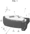
- the vehicle lamp 10 according to a first embodiment which is an embodiment of the vehicle lamp according to the present disclosure, will be explained with reference to FIGS. 1 to 12 .
- the vehicle lamp 10 of the first embodiment is used as a headlamp device of a vehicle such as an automobile.
- the headlamp device is mounted on each of right and left sides of the front of a vehicle, and is configured such that the vehicle lamp 10 is provided in a lamp chamber formed by a lamp housing whose open front end is covered with an outer lens 15 (see FIG. 5 ).
- the vehicle lamp 10 is provided in the lamp chamber via an up-down direction optical axis adjustment mechanism and a left-right direction optical axis adjustment mechanism, and appropriately irradiates the front of the vehicle.
- a direction in which a vehicle mounted with the vehicle lamp 10 travels is defined as a front-rear direction (Z in the drawings), a vertical direction when the front-rear direction is along a horizontal plane is defined as an up-down direction (Y in the drawings), and a direction orthogonal to the front-rear direction and the up-down direction (horizontal direction) is defined as a width direction (X in the drawings).
- a vehicle lamp 10 provided on a right side of the vehicle and a vehicle lamp 10 provided on a left side of the vehicle have basically the same configuration, but are reversed in a width direction (left and right). Therefore, explanation will be made below by using the vehicle lamp 10 provided on the right side.
- the vehicle lamp 10 constitutes a projector-type lamp unit in which a light source portion 12, a reflector member 13, and a projection lens 14 are attached to an attachment member 11.
- the attachment member 11 is a section where the light source portion 12 is provided, is formed of an aluminum plate, aluminum die-casting, or resin which has thermal conductivity, and functions as a heat sink that releases heat generated in the light source portion 12 to the outside as a whole.
- the attachment member 11 includes a light source attachment portion 21 and a lens attachment portion 22.
- the light source attachment portion 21 has a flat plate shape orthogonal to the up-down direction, and the light source portion 12 is attached to a predetermined position.
- the light source attachment portion 21 is provided with three light shielding walls 23.
- Each of the light shielding walls 23 has a plate shape protruding upward in the up-down direction in such a way as to be orthogonal to the light source attachment portion 21, and individually corresponds to a first light source 31, a second light source 32, and a fourth light source 34, which will be described below, of the light source portion 12.
- Each of the light shielding walls 23 is provided on the front side in the front-rear direction with respect to the corresponding light source, and absorbs or diffuses light from the corresponding light source.
- Each of the light shielding walls 23 prevents the light from the corresponding light source from illuminating an upper side of a cutoff line CL in a low-beam light distribution pattern LP, which will be described below, formed by the light from the corresponding light source, on a screen where a horizontal line H and a vertical line V intersect with each other at a center position O on a projected optical axis Lp, and the position of the light shielding wall 23 with respect to the corresponding light source is set.
- the lens attachment portion 22 has a flat plate shape substantially orthogonal to the up-down direction, is provided on a front side of the light source attachment portion 21 in the front-rear direction, and is positioned lower than the light source attachment portion 21 in the up-down direction with a step.
- the lens attachment portion 22 constitutes a section to which the projection lens 14 is attached, and the projection lens 14 is positioned on a front side of the light source portion 12 attached to the light source attachment portion 21 in the front-rear direction.
- the attachment member 11 is provided with four positioning holes 11a and three screw insertion holes 11b. Each positioning hole 11a and each screw insertion hole 11b are provided in pairs. A positioning protrusion 13a of the reflector member 13, which will be described below, can be fitted into each positioning hole 11a. A screw 24 can be inserted into each screw insertion hole 11b.
- the attachment member 11 may be provided with a plurality of heat dissipation fins, and heat generated by the light source portion 12 attached to the light source attachment portion 21 may be dissipated to the outside mainly from each heat dissipation fin.
- the attachment member 11 is fixed to a lamp housing via a bracket not to be illustrated.
- a cooling fan unit may be provided as appropriate in order to increase cooling efficiency.
- the light source portion 12 includes a first light source 31, a second light source 32, a third light source 33, a fourth light source 34 (see FIG. 2 , etc.), a connector terminal 35, and a substrate 36 on which these components are mounted.
- the four light sources (31 to 34) are configured by a light emitting element such as a light emitting diode (LED).
- the four light sources (31 to 34) are provided at positions corresponding to respective reflector portions (41 to 44) to be described below. This positional relationship will be described below.
- the connector terminal 35 is electrically connected to a wiring pattern of the substrate 36, and a connection connector connected to a lighting control circuit is detachable.
- the connector terminal 35 is provided at a lower end portion of the substrate 36 in the up-down direction, and the connection connector can be easily attached and detached.
- the connector terminal 35 makes it possible to supply electric power from the lighting control circuit to each of the light sources (31 to 34) via the wiring pattern by attaching the connection connector thereto.
- the substrate 36 has a plate shape formed of an aluminum substrate, and each of the light sources (31 to 34) is mounted on the substrate 36.
- the substrate 36 may be formed of a resin material such as a glass epoxy substrate, or may be formed of an other material.
- the substrate 36 is provided with a wiring pattern that electrically connects each of the light sources (31 to 34) and the connector terminal 35.
- a positioning hole 36a is provided corresponding to the positioning hole 11a at the center of the light source attachment portion 21 of the attachment member 11, and a screw insertion hole 36b is provided corresponding to the screw insertion hole 11b near the positioning hole 11a.
- the substrate 36 is attached between the attachment member 11 (light source attachment portion 21) and the reflector member 13 by inserting the positioning protrusion 13a of the reflector member 13, which will be described below, into the positioning hole 36a and screwing the screw 24, which is inserted into the screw insertion hole 36b, into a screw hole 13b of the reflector member 13, which will be described below. Then, the substrate 36 makes the mounted light sources (31 to 34) face the corresponding reflector portions (41 to 44), respectively. The substrate 36 appropriately supplies electric power from the lighting control circuit via the connector terminal 35 and appropriately turns on the light sources (31 to 34).
- the substrate 36 is provided with a light shielding wall slit 37 in front of each of the first light source 31, the second light source 32, and the fourth light source 34.
- the light shielding wall slit 37 is positioned in front of the corresponding light source, and can receive each light shielding wall 23 provided in the light source attachment portion 21 of the attachment member 11. Therefore, when the light source portion 12 is attached between the attachment member 11 and the reflector member 13, the light shielding wall 23 can be positioned in front of each of the first light source 31, the second light source 32, and the fourth light source 34 through the light shielding wall slit 37.
- the light source portion 12 it is possible to prevent the light from the first light source 31, the second light source 32, and the fourth light source 34 from illuminating the upper side of the cutoff line CL in the low-beam light distribution pattern LP to be described below.
- the reflector member 13 is a molded product made of a resin material, and is integrally provided with a first reflector portion 41, a second reflector portion 42, a third reflector portion 43, and a fourth reflector portion 44 (see FIG. 2 , etc.).
- Each of the reflector portions (41 to 44) has a reflective surface Rs curved in such a way as to cover the corresponding light source (31 to 34), and the reflective surface Rs reflects light emitted from the corresponding light source (31 to 34) to the projection lens 14 side.
- the reflective surface Rs is provided on the inner side of each reflector portion (41 to 44).
- Each reflective surface Rs is a bowl-shaped free-form surface based on an ellipse having a first focal point at the corresponding light source (31 to 34) (the center position thereof or the vicinity thereof) and a second focal point near a lens portion (51 to 54), which will be described below, of the corresponding projection lens 14.
- each of the reflector portions (41 to 44) can cause the light emitted from each of the light sources (31 to 34) near the first focal point to efficiently travel to the corresponding lens portion (51 to 54).
- the positional relationship between the reflector portions (41 to 44) and the like will be described below.
- the reflector member 13 is provided with four positioning protrusions 13a and three screw holes 13b.
- Each positioning protrusion 13a is formed in a rod shape protruding downward in the up-down direction at a position where an optical path from each of the reflector portions (41 to 44) is not blocked.
- Each screw hole 13b is provided in the vicinity of the corresponding positioning protrusion 13a at a position where the optical path from each of the reflector portions (41 to 44) is not blocked, and can be fixed by screwing the screw 24.
- the reflector member 13 is fixed to the attachment member 11 by screwing the screw 24 into each screw hole 13b while being positioned by each positioning protrusion 13a in a state where the light source portion 12 is interposed between the reflector member 13 and the light source attachment portion 21. Then, since the light source portion 12 is fixed to an upper surface (21a) of the light source attachment portion 21 of the attachment member 11, the upper surface (21a) becomes an attachment surface 21a to which the light source portion 12 (the light sources (31 to 34) thereof) and the reflector portions (41 to 44) of the reflector member 13 are attached.
- the reflector member 13 is provided with three partition wall portions 25.
- Each of the partition wall portions 25 is positioned between a first lens portion 51 and a second lens portion 52, between the second lens portion 52 and a third lens portion 53, and between the third lens portion 53 and a fourth lens portion 54, which will be described below, of the projection lens 14, and has a plate shape extending in the up-down direction.
- the partition wall portions 25 prevents light passing through each of the irradiation units (61 to 64), which will be described below, from traveling to an other adjacent irradiation unit.
- the projection lens 14 projects light reflected by the reflector member 13 (each reflective surface Rs thereof) to the front of the vehicle, and forms a predetermined light distribution pattern in cooperation therewith.
- the projection lens 14 is a molded product made of a resin material, and is integrally provided with the first lens portion 51, the second lens portion 52, the third lens portion 53, and the fourth lens portion 54 (see FIG. 2 , etc.).
- Each of the lens portions (51 to 54) is positioned at a position facing the corresponding reflector portion (41 to 44), i.e., in a direction in which the light from the corresponding light source (31 to 34) is reflected by the reflector portion (41 to 44).
- the fourth lens portion 54, the first lens portion 51, the second lens portion 52, and the third lens portion 53 are provided in this order from the inner side (a right side in FIG. 4 and a left side in FIG. 5 ) of the vehicle in the width direction.
- a focal point (rear focal point) is positioned near an inner wall section (41b to 44b), which will be described below, of the corresponding reflector portion (41 to 44).
- Each of the lens portions (51 to 54) irradiates light from the corresponding reflector portion (41 to 44), thereby forming, in an appropriately superimposed manner, a plurality of light distribution images of the inner wall section (41b to 44b) (predetermined area in the vicinity thereof) at positions according to optical characteristics on a screen where a horizontal line H and a vertical line V intersect with a center position O of irradiation by the vehicle lamp 10 as an origin.
- the optical characteristics can be set by adjusting a curvature (surface shape) of each of the lens portions (51 to 54) for each place, and in the first embodiment, the curvature is set to be gradually changed.
- the first lens portion 51 is a convex lens
- the second lens portion 52 is a concave lens
- the third lens portion 53 is a concave lens
- the fourth lens portion 54 is a concave lens.
- the fourth lens portion 54 and the first lens portion 51 extend in the width direction.
- the second lens portion 52 adjacent to the first lens portion 51 is inclined slightly further rearward than the first lens portion 51 in such a way as to be displaced rearward as it extends toward the outer side.
- the third lens portion 53 adjacent to the second lens portion 52 is inclined rearward more largely than the second lens portion 52 in such a way as to be displaced rearward as it extends toward the outer side.
- An axis line of the third lens portion 53 of the first embodiment is aligned with a third projected optical axis Lp3, which will be described below, of the third reflector portion 43, and the third lens portion 53 is inclined outward at an angle between 40 degrees and 80 degrees with respect to the front-rear direction.
- the inclination is 60 degrees in the first embodiment.
- the projection lens 14, as a whole is directed (slanted) rearward in the front-rear direction as it extends from the inner side to the outer side in the width direction, and has the same shape as the outer lens 15 (see FIG. 5 ), and therefore, the projection lens 14 can have an appearance with a sense of unity.
- the first lens portion 51 is a convex lens in which a first emission surface 51a is a substantially smooth curved surface and a first incident surface 51b is a convex surface that bulges toward the first light source 31 (first reflector portion 41) side.
- the second lens portion 52 is a concave lens in which a second emission surface 52a is a substantially smooth curved surface and a second incident surface 52b is a concave surface that is concave toward the side opposite to the second light source 32 (second reflector portion 42).
- the third lens portion 53 is a concave lens in which a third emission surface 53a is a substantially smooth curved surface and a third incident surface 53b is a concave surface that is concave toward the side opposite to the third light source 33 (third reflector portion 43).
- the fourth lens portion 54 is a concave lens in which a fourth emission surface 54a is a substantially smooth curved surface and a fourth incident surface 54b is a concave surface that is concave toward the side opposite to the fourth light source 34 (fourth reflector portion 44).
- a curvature of each of the incident surfaces (51b to 54b) is set according to optical settings in each of the irradiation units (61 to 64) to be described below.
- the fourth emission surface 54a, the first emission surface 51a, and the second emission surface 52a are continuously arranged from the inner side in the width direction, which form a single curved surface.
- the single curved surface means that there is no bent section and a change in curvature is continuous.
- the fourth emission surface 54a, the first emission surface 51a, and the second emission surface 52a can be made to appear to form a single surface, thereby improving the appearance.
- the third emission surface 53a of the third lens portion 53 is a single curved surface.
- a bent surface portion 55 is provided between the second lens portion 52 (the second emission surface 52a thereof) and the third lens portion 53 (the third emission surface 53a thereof).
- the bent surface portion 55 forms a bent and continuous section between the second emission surface 52a of the second lens portion 52 and the third emission surface 53a of the third lens portion 53.
- the second emission surface 52a and the third emission surface 53a are each formed as a single curved surface extending in different directions, but the emission surfaces are continuous while changing their directions by the bent surface portion 55.
- the four emission surfaces (51a to 54a) can be formed into a unified and integrated design as a whole constituted by two smooth curved surfaces without irregularities, and can be formed to be directed (slanted) rearward as it extends toward the outer side.
- the second lens portion 52 can be made substantially orthogonal to a second projected optical axis Lp2 of a second irradiation unit 62 to be described below
- the third lens portion 53 can be made substantially orthogonal to a third projected optical axis Lp3 of a third irradiation unit 63 to be described below.
- a common reference curve that is smoothly continuous and gently curved is set on the incident surface side from the second lens portion 52 to the third lens portion 53, and the second incident surface 52b and the third incident surface 53b are concave surfaces that are recessed with respect to the reference curve.
- the second incident surface 52b and the third incident surface 53b can be adjacent to each other without causing a step therebetween, and it is possible to prevent unintended light and dark from being formed on each light distribution pattern P due to light caused by the step.
- the second incident surface 52b and the third incident surface 53b are mutually concave surfaces, it is possible to suppress light from one irradiation unit from being incident on the incident surface of the other irradiation unit, compared to a case where the incident surface of the one irradiation unit is a concave surface and the incident surface of the other irradiation unit is a convex surface.
- the projection lens 14 is provided with two positioning holes 14a and one screw insertion hole 14b.
- Each positioning hole 14a is provided on both sides outside an area where the lens portions (51 to 54) are provided in the width direction, and the corresponding positioning protrusions 13a of the reflector member 13 can be fitted into the positioning holes 14a.
- the screw 24 can be inserted into the screw insertion hole 14b.
- the projection lens 14 is attached between the attachment member 11 (lens attachment portion 22) and the reflector member 13 by inserting each positioning protrusion 13a of the reflector member 13 into the positioning hole 14a and screwing the screw 24 inserted into the screw insertion hole 14b into the screw hole 13b of the reflector member 13.
- the projection lens 14 has a positional relationship in which each of the lens portions (51 to 54) is opposed to the corresponding reflector portion (41 to 44).
- each of the reflector portions (41 to 44) cooperates with the corresponding light source (31 to 34) and lens portion (51 to 54), thereby forming an irradiation unit for forming a predetermined light distribution pattern.
- the first reflector portion 41 constitutes a first irradiation unit 61 by the first light source 31 and the first lens portion 51
- the second reflector portion 42 constitutes a second irradiation unit 62 by the second light source 32 and the second lens portion 52.
- the third reflector portion 43 constitutes a third irradiation unit 63 by the third light source 33 and the third lens portion 53
- the fourth reflector portion 44 constitutes a fourth irradiation unit 64 by the fourth light source 34 and the fourth lens portion 54.
- an axis line of each of the reflector portions (41 to 44) is set as the projected optical axis Lp.
- the axis line (each projected optical axis Lp) is the major axis of a basic ellipse in each reflective surface Rs.
- the axis line of the first irradiation unit 61 is referred to as a first projected optical axis Lp1
- the axis line of the second irradiation unit 62 is referred to as a second projected optical axis Lp2
- the axis line of the third irradiation unit 63 is referred to as a third projected optical axis Lp3
- the axis line of the fourth irradiation unit 64 is referred to as a fourth projected optical axis Lp4 (see FIG. 4 ).
- the first reflector portion 41 is provided on the center side in the width direction, and the first projected optical axis Lp1 is aligned with the front-rear direction.
- the first projected optical axis Lp1 also functions as the projected optical axis Lp in the vehicle lamp 10.
- the first reflector portion 41 is formed in a bowl shape on a horizontal plane, and an open end 41a from which light is emitted is positioned on the front side in the front-rear direction, and an inner wall section 41b, which is a vertex of the bowl shape, is positioned on the rear side in the front-rear direction.
- the first lens portion 51 of the projection lens 14 is positioned on the front side of the first reflector portion 41 in the front-rear direction, i.e., on the first projected optical axis Lp1.
- a lower end of the inner wall section 41b is a cutoff forming surface 41c (see FIGS. 3 , 4 , etc.).
- the cutoff forming surface 41c has a shape in which two horizontal edges having different heights at the lower end are connected by an inclined edge.
- the first reflector portion 41 reflects light from the first light source 31 located at (near) the first focal point of the reflective surface Rs toward the first lens portion 51.
- the first lens portion 51 projects the light reflected by the first reflector portion 41 in a direction of the first projected optical axis Lp1.
- the first lens portion 51 is formed as a convex lens, the light from the first reflector portion 41 is caused to travel in the direction of the first projected optical axis Lp1 while being collected. Then, the first lens portion 51 forms a light distribution image of the inner wall section 41b including the cutoff forming surface 41c on a screen where the horizontal line H and the vertical line V intersect with each other on the projected optical axis Lp (first projected optical axis Lp1). Even when the vehicle lamp 10 is provided on the left side of the vehicle, a relationship between a direction of inclination and a height of the cutoff forming surface 41c is not reversed in the width direction. Namely, the vehicle lamps 10 on the right and left sides of the vehicle are reversed in the width direction, but the inclinations of the cutoff forming surfaces 41c are set in the same direction.
- the first irradiation unit 61 forms a first light distribution pattern P1 as a collected light distribution pattern obtained by collecting the light from the first light source 31 on the above-described screen.
- a cutoff line CL in which two horizontal edges having different heights are connected to each other by an inclined edge is provided on the upper side.
- the first light distribution pattern P1 positions the cutoff line CL on the projected optical axis Lp, emphasizes brightness by gathering light below the cutoff line CL, and clarifies the brightness and darkness of the cutoff line CL.
- the second reflector portion 42 is provided adjacent to the first reflector portion 41 on the outer side in the width direction.
- the second projected optical axis Lp2 of the second reflector portion 42 is aligned with the front-rear direction or is slightly inclined further outward than the front-rear direction.
- the second reflector portion 42 is formed in a bowl shape on a horizontal plane, and an open end 42a from which light is emitted is positioned on the front side in the front-rear direction, and an inner wall section 42b, which is a vertex of the bowl shape, is positioned on the rear side in the front-rear direction.
- the second lens portion 52 of the projection lens 14 is positioned on the front side of the second reflector portion 42 in the front-rear direction, i.e., on the second projected optical axis Lp2.
- the second reflector portion 42 is located adjacent to the first reflector portion 41 further outward than the first reflector portion 41 in the width direction
- the second lens portion 52 is located adjacent to the first lens portion 51 further outward than the first lens portion 51 in the width direction.
- the second reflector portion 42 reflects light from the second light source 32 located at (near) the first focal point of the reflective surface Rs toward the second lens portion 52.
- the second lens portion 52 projects the light reflected by the second reflector portion 42 onto the second projected optical axis Lp2.
- the second lens portion 52 is a concave lens and the second projected optical axis Lp2 is slightly inclined outward, the light from the second reflector portion 42 is diffused and travels in a direction of the second projected optical axis Lp2, i.e., slightly further outward (to the left side in FIGS.
- the second lens portion 52 forms a plurality of light distribution images of the inner wall section 42b on the screen where the horizontal line H and the vertical line V intersect with each other on the projected optical axis Lp in an appropriately superimposed manner.
- a degree of concavity of the second incident surface 52b that is a concave surface, i.e., a curvature of the second incident surface 52b is smaller than that of the third incident surface 53b and larger than that of the fourth incident surface 54b.
- the second irradiation unit 62 forms a second light distribution pattern P2 as a large diffusion light distribution pattern in which the light from the second light source 32 is largely diffused on the above-described screen.
- the center of brightness is positioned further outward (to the right side) than the projected optical axis Lp in the width direction.
- the second light distribution pattern P2 is largely expanded to the outer side of the first light distribution pattern P1 while partially overlapping with the first light distribution pattern P1 below the cutoff line CL of the first light distribution pattern P1, and brightens a wider area than the first light distribution pattern P1.
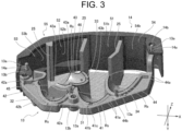
- the third reflector portion 43 is provided between the first reflector portion 41 and the second reflector portion 42 in the width direction and on a front side of the first reflector portion 41 and the second reflector portion 42 in the front-rear direction.
- the third reflector portion 43 is positioned forward to a position in contact with the first reflector portion 41 (the open end 41a thereof) and the second reflector portion 42 (the open end 42a thereof) in the front-rear direction, thereby being positioned between the first reflector portion 41 and the second reflector portion 42 which are adjacent to each other in the width direction.
- the third projected optical axis Lp3 of the third reflector portion 43 is inclined outward at an angle between 40 degrees and 80 degrees with respect to the front-rear direction, and the inclination is 60 degrees in the first embodiment.
- the third reflector portion 43 is formed in a bowl shape on a horizontal plane, and an open end 43a from which light is emitted is positioned on the front side in the front-rear direction, and an inner wall section 43b, which is a vertex of the bowl shape, is positioned on the rear side in the front-rear direction.
- the third lens portion 53 of the projection lens 14 is located at a position facing the third reflector portion 43, i.e., on the third projected optical axis Lp3.
- the third lens portion 53 is positioned further outward than the second lens portion 52 in the width direction as described above.
- the third reflector portion 43 is positioned between the first reflector portion 41 and the second reflector portion 42 in the width direction, but the third projected optical axis Lp3 is inclined outward by 60 degrees. In this way, in the width direction, the order of arrangement of the second reflector portion 42 and the third reflector portion 43 and the order of arrangement of the second lens portion 52 and the third lens portion 53 are reversed. Therefore, optical paths (both projected optical axes Lp2 and Lp3) of the second irradiation unit 62 and the third irradiation unit 63 intersect with each other.
- the third projected optical axis Lp3 is largely inclined, whereby the third reflector portion 43 is inclined largely outward with respect to the first reflector portion 41 and the second reflector portion 42. Therefore, in the third reflector portion 43, the vicinity of the inner wall section 43b (third light source 33) is positioned on the front side of the first light source 31 in the front-rear direction.
- an optical path of the first irradiation unit 61 i.e., a trajectory along which effective light from the first light source 31 used for forming the first light distribution pattern P1 is reflected by the first reflector portion 41 and travels to the first lens portion 51, is reduced in dimension in the width direction at an intermediate position from the first reflector portion 41 to the first lens portion 51 (see FIG.
- the third reflector portion 43 is disposed on the front side of the first light source 31 in accordance with a mode of the optical path of the first irradiation unit 61 (the effective light trajectory described above) in such a way as to be able to suppress the traveling of the light in the first irradiation unit 61 from being blocked as much as possible.
- the position and size of the third reflector portion 43 on the optical path of the first irradiation unit 61 are set in such a way that the third reflector portion 43 can be suppressed from blocking the optical path of the first irradiation unit 61.
- half or more of the third reflector portion 43 on the open end 43a side is positioned on an optical path of the second irradiation unit 62, i.e., on a trajectory along which effective light from the second light source 32 used for forming the second light distribution pattern P2 is reflected by the second reflector portion 42 and travels to the second lens portion 52.
- one side of the third reflector portion 43 with the third projected optical axis Lp3 interposed therebetween is located on the second light source 32 (second reflector portion 42) side, and the other side on the opposite side with the third projected optical axis Lp3 interposed therebetween is located on the second lens portion 52 side.
- a light-source-side cutout portion 45 is provided on one second light source 32 side, and an opposite-side cutout portion 46 is provided on the other second lens portion 52 side.
- the light-source-side cutout portion 45 and the opposite-side cutout portion 46 are formed by partially cutting out the third reflector portion 43 in order to prevent the traveling of the light from the second light source 32, which is reflected by the second reflector portion 42 and travels toward the second lens portion 52, from being blocked.
- the light-source-side cutout portion 45 and the opposite-side cutout portion 46 of the first embodiment are cut out in a curved shape with the second projected optical axis Lp2 or the vicinity thereof as a center.
- the optical path of the second irradiation unit 62 has a small dimension in the width direction at an intermediate position from the second reflector portion 42 to the second lens portion 52 (see FIG. 6 ). Therefore, the light-source-side cutout portion 45 is cut out larger than the opposite-side cutout portion 46, i.e., has a radius of curvature larger than that of the opposite-side cutout portion 46.
- the light-source-side cutout portion 45 is largely cut out and the opposite-side cutout portion 46 is cut out to be smaller than the light-source-side cutout portion 45 in such a way that the reflective surface Rs in the third reflector portion 43 is increased as much as possible while suppressing the optical path of the second irradiation unit 62 from being blocked, in the third reflector portion 43.
- the both cutout portions (45 and 46) can secure the optical paths of both the second irradiation unit 62 and the third irradiation unit 63 in a well-balanced manner, and can appropriately form both the second light distribution pattern P2 and a third light distribution pattern P3.
- the third reflector portion 43 reflects light from the third light source 33 located at (near) the first focal point of the reflective surface Rs toward the third lens portion 53.
- the third lens portion 53 projects the light reflected by the third reflector portion 43 onto the third projected optical axis Lp3.
- the third lens portion 53 is a concave lens and the third projected optical axis Lp3 is largely inclined outward, the light reflected by the third reflector portion 43 is diffused and travels in a third projected optical axis Lp3 direction, i.e., largely further outward (to the left side in FIGS.
- the third lens portion 53 forms a plurality of light distribution images of the inner wall section 43b on a screen where the horizontal line H and the vertical line V intersect with each other on the projected optical axis Lp in an appropriately superimposed manner.
- a degree of concavity of the third incident surface 53b i.e., a curvature of the third incident surface 53b is set to be large, compared to the other concave incident surfaces (52b and 54b).
- the third irradiation unit 63 diffuses the light from the third light source 33 to form a third light distribution pattern P3 on the above-described screen.
- the center of brightness is positioned largely further outward (to the right side) than the projected optical axis Lp in the width direction.
- the third light distribution pattern P3 brightens a wide area on the outer side (right side) in the width direction while partially overlapping with the second light distribution pattern P2.
- the third light distribution pattern P3 can irradiate a side of a low-beam light distribution pattern LP to be described below (see FIG.
- the third light distribution pattern P3 brightens a range of 30 degrees to 90 degrees outward from the center position O (projected optical axis Lp) along the horizontal line H.
- the fourth reflector portion 44 is provided adjacent to the first reflector portion 41 on the inner side of the first reflector portion 41 in the width direction.
- the fourth projected optical axis Lp4 of the fourth reflector portion 44 is aligned with the front-rear direction or is slightly inclined further inward than the front-rear direction.
- the fourth reflector portion 44 is formed in a bowl shape on a horizontal plane, and an open end 44a from which light is emitted is positioned on the front side in the front-rear direction, and an inner wall section 44b, which is a vertex of the bowl shape, is positioned on the rear side in the front-rear direction.
- the fourth lens portion 54 of the projection lens 14 is positioned on the front side of the fourth reflector portion 44 in the front-rear direction, i.e., on the fourth projected optical axis Lp4.
- the fourth reflector portion 44 is adjacent to the first reflector portion 41 on the inner side in the width direction
- the fourth lens portion 54 is adjacent to the first lens portion 51 on the inner side in the width direction.
- the fourth reflector portion 44 reflects light from the fourth light source 34 located at (near) the first focal point of the reflective surface Rs thereof toward the fourth lens portion 54.
- the fourth lens portion 54 projects the light reflected by the fourth reflector portion 44 onto the fourth projected optical axis Lp4.
- the fourth lens portion 54 is a concave lens and the fourth projected optical axis Lp4 is slightly inclined inward, the light reflected by the fourth reflector portion 44 is diffused and travels in a direction of the fourth projected optical axis Lp4, i.e., slightly further inward (to the right side in FIGS.
- the fourth lens portion 54 forms a plurality of light distribution images of the inner wall section 44b on the screen where the horizontal line H and the vertical line V intersect with each other on the projected optical axis Lp in an appropriately superimposed manner.
- a degree of concavity of the fourth incident surface 54b that is a concave surface, i.e., a curvature of the fourth incident surface 54b is set to be small, compared to the other concave incident surfaces (52b and 53b).
- the fourth irradiation unit 64 forms a fourth light distribution pattern P4 as a medium diffusion light distribution pattern in which the light from the fourth light source 34 is diffused on the above-described screen.
- the center of brightness is positioned further inward (to the left side) than the projected optical axis Lp in the width direction.
- the fourth light distribution pattern P4, below the cutoff line CL of the first light distribution pattern P1, includes substantially the entire area of the first light distribution pattern P1 and expands largely to the left side of the first light distribution pattern P1, and brightens an area wider than the first light distribution pattern P1.
- the vehicle lamp 10 can form the low-beam light distribution pattern LP as illustrated in FIG. 11 by turning on the first light source 31, the second light source 32, and the fourth light source 34 and simultaneously forming and superimposing the first light distribution pattern P1, the second light distribution pattern P2, and the fourth light distribution pattern P4.
- the low-beam light distribution pattern LP has a cutoff line CL on the projected optical axis Lp, and can brighten a large area in the width direction below the cutoff line CL while making the vicinity of the projected optical axis Lp brightest.
- the vehicle lamp 10 turns on the third light source 33 and forms the third light distribution pattern P3, thereby making it possible to brighten the outer side (right side in FIG. 12 ) of the low-beam light distribution pattern LP while partially overlapping with the low-beam light distribution pattern LP as illustrated in FIG. 12 .
- the vehicle lamp 10 can secure a wide field of view on the right side of the low-beam light distribution pattern LP in addition to the low-beam light distribution pattern LP.
- the vehicle lamp 10 turns on the third light source 33 in conjunction with such operations.
- the vehicle lamp 10 may form the third light distribution pattern P3 by turning on the third light source 33 in response to an operation on an operation portion for turning on the third light source 33 provided in the vehicle. Further, the vehicle lamp 10 may always form the third light distribution pattern P3 when forming the low-beam light distribution pattern LP.
- the third light distribution pattern P3 is formed on the left side of the low-beam light distribution pattern LP in conjunction with an operation of turning the steering wheel largely to the left or an operation of turning on a left blinker.
- the vehicle lamp 10 integrally includes the third irradiation unit 63 that forms the third light distribution pattern P3 in addition to the first irradiation unit 61, the second irradiation unit 62, and the fourth irradiation unit 64 that form the low-beam light distribution pattern LP. Therefore, when the vehicle lamp 10 is mounted on the vehicle, it is possible to eliminate an adjustment operation for positioning between the irradiation units (61 to 64), and it is possible to increase accuracy of the relative positional relationship between the irradiation units (61 to 64). In addition, in the vehicle lamp 10, it is possible to reduce the number of parts for attachment and to simplify the attachment work, compared to a case where the irradiation units (61 to 64) are individually mounted on the vehicle.
- the vehicle lamp 10 is provided with the first lens portion 51 that forms the first light distribution pattern P1 by collecting light from the first light source 31 and the second lens portion 52 that forms the second light distribution pattern P2 by diffusing the light from the second light source 32 in the projection lens 14.
- the first lens portion 51 and the second lens portion 52 are provided adjacent to each other in sequence from the inner side in the width direction.
- the vehicle lamp 10 forms the low-beam light distribution pattern LP (also the fourth light distribution pattern P4 in the first embodiment) by simultaneously forming the first light distribution pattern P1 having the cutoff line CL by the innermost first lens portion 51 and the second light distribution pattern P2 formed by the second lens portion 52 further outside than the first lens portion 51.
- the vehicle lamp 10 forms the cutoff line CL by the light from the first lens portion 51 on the inner side, it is possible to easily and clearly form the cutoff line CL in the low-beam light distribution pattern LP formed in front of the vehicle. Further, since the vehicle lamp 10 forms the second light distribution pattern P2 by the light from the second lens portion 52 further outside than the first lens portion 51, it is possible to easily make the second light distribution pattern P2 larger than the first light distribution pattern P1. These are because the first lens portion 51 on the inner side is more advantageous in gathering light around the cutoff line CL located in front of the vehicle, and the second lens portion 52 on the outer side is more advantageous in diffusing the light while at least partially overlapping with the first light distribution pattern P1. Therefore, the vehicle lamp 10 can form the first light distribution pattern P1 and the second light distribution pattern P2 at the same time, thereby forming an appropriate low-beam light distribution pattern LP that irradiates a large area while emphasizing the cutoff line CL.
- the vehicle lamp 10 is provided with the third irradiation unit 63 that forms the third light distribution pattern P3 for irradiating a side of the low-beam light distribution pattern LP, and the third lens portion 53 is provided adjacent to the outer side of the second lens portion 52 in the width direction, in the projection lens 14. Therefore, in the vehicle lamp 10, an optical path from the second light source 32 to the second lens portion 52 and an optical path from the third light source 33 to the third lens portion 53 can be made to intersect with each other.
- the vehicle lamp 10 forms the third light distribution pattern P3 by emitting the light from the third light source 33 further inside than the second light source 32 from the third lens portion 53 further outside than the second lens portion 52, and thus the third light distribution pattern P3 can be easily positioned on the outer side of the first light distribution pattern P1 or the second light distribution pattern P2. Therefore, the vehicle lamp 10 can appropriately form the low-beam light distribution pattern LP having the cutoff line CL and the third light distribution pattern P3 on the side of the low-beam light distribution pattern LP.
- the projection lens 14 is directed (slanted) rearward in the front-rear direction as it extends from the inner side to the outer side in the width direction. Therefore, in the vehicle lamp 10, since a distance between the second reflector portion 42 and the second lens portion 52 in the second irradiation unit 62 can be made smaller than that in the first irradiation unit 61 or the fourth irradiation unit 64, a focal length of the second lens portion 52 can be made smaller.
- the second irradiation unit 62 can easily diffuse the light from the second light source 32, compared to a case where the second irradiation unit 62 is disposed at the position of the first irradiation unit 61.
- the second irradiation unit 62 can easily form the second light distribution pattern P2 that is largely expanded while the center of brightness is positioned further outward than the projected optical axis Lp in the width direction.
- the projection lens 14 is slanted as described above, a distance between the first reflector portion 41 and the first lens portion 51 in the first irradiation unit 61 can be made larger than that in the second irradiation unit 62. Therefore, a focal length of the first lens portion 51 can be increased. For this reason, by disposing the first irradiation unit 61 further inward than the second irradiation unit 62, it is possible to easily collect the light from the first light source 31 compared to a case where the first irradiation unit 61 is disposed at the position of the second irradiation unit 62.
- the first lens portion 51 of the first irradiation unit 61 extends along the width direction, it is possible to easily form the center of brightness of the first light distribution pattern P1, in which the brightness is emphasized by gathering light and the cutoff line is clarified, in the vicinity of the projected optical axis Lp.
- the conventional vehicle lamp is provided with a low-beam light distribution unit and an additional light distribution unit, whereby an additional light distribution pattern (a third light distribution pattern P3 in the present invention) beside a low-beam light distribution pattern is formed.
- the additional light distribution unit is disposed on the outer side of the low-beam light distribution unit, which leads to an increase in size.
- the low-beam light distribution unit is provided on the inner side in the width direction while facing the front side in the front-rear direction
- the additional light distribution unit is provided on the outer side in the width direction while being inclined outward with respect to the front-rear direction.
- a large gap is formed between emission positions of the low-beam light distribution unit and the additional light distribution unit, and an inner panel is provided in the gap to cover the gap.
- an inner panel is provided in the gap to cover the gap.
- the first reflector portion 41 and the second reflector portion 42 are provided adjacent to each other in the width direction on the attachment surface 21a of the attachment member 11, and the third reflector portion 43 is provided between the first reflector portion 41 and the second reflector portion 42 in the width direction and on the front side in the front-rear direction. Therefore, in the vehicle lamp 10, the three reflector portions (41, 42, and 43) are not simply arranged in the width direction, but are disposed in such a way as to be shifted also in the front-rear direction, whereby the reflector portions can be provided by efficiently using the attachment surface 21a, and an increase in size can be suppressed.
- the third projected optical axis Lp3 of the third reflector portion 43 which forms the third light distribution pattern P3 that irradiates the side of the low-beam light distribution pattern LP, is inclined outward by 60 degrees with respect to the front-rear direction. Therefore, in the vehicle lamp 10, since the third reflector portion 43 is provided in front of the first reflector portion 41 and the second reflector portion 42 in which the projected optical axes (Lp1 and Lp2) are substantially along the front-rear direction in order to form the low-beam light distribution pattern LP, the emission positions of light from the three irradiation units (61 to 63) can be made close to each other.
- the three lens portions (51 to 53) of the projection lens 14 can be arranged adjacent to each other, and the appearance can be improved compared to the above-described conventional vehicle lamp.
- the partition wall portion 25 is provided between the respective lens portions (51 to 54), but each partition wall portion 25 prevents light passing through each irradiation unit (61 to 64) from traveling to the other adjacent irradiation unit and do not hide the light, and thus deterioration of the appearance is suppressed.
- the vehicle lamp 10 as an example of the vehicle lamp according to the present disclosure can acquire the following effects.
- the second light distribution pattern P2 is formed simultaneously with the first light distribution pattern P1, thereby forming at least a part of the low-beam light distribution pattern LP, and the first reflector portion 41 and the second reflector portion 42 are provided on the attachment surface 21a in such a way as to be adjacent to each other in the width direction of the vehicle.
- the third reflector portion 43 is provided on the attachment surface 21a between the first reflector portion 41 and the second reflector portion 42 in the width direction and on the front side of the first reflector portion 41 and the second reflector portion 42 in the front-rear direction of the vehicle.
- the three reflector portions (41, 42, and 43) are not simply arranged in the width direction, but are disposed in such a way as to be shifted also in the front-rear direction, whereby the reflector portions can be provided by efficiently using the attachment surface 21a, and an increase in size can be suppressed.
- the first reflector portion 41 is provided further inward than the second reflector portion 42 in the width direction. Therefore, since the vehicle lamp 10 forms the cutoff line CL by the light from the first reflector portion 41 on the inner side, it is possible to easily and clearly form the cutoff line CL in the low-beam light distribution pattern LP formed in front of the vehicle. Further, since the vehicle lamp 10 forms the second light distribution pattern P2 by the light from the second reflector portion 42 further outside than the first lens portion 51, it is possible to easily make the second light distribution pattern P2 larger than the first light distribution pattern P1.
- a first axis line (the first projected optical axis Lp1) of the first reflector portion 41 is along the front-rear direction
- a third axis line (the third projected optical axis Lp3) of the third reflector portion 43 is inclined outward at an angle between 40 degrees and 80 degrees with respect to the front-rear direction. Therefore, in the vehicle lamp 10, the traveling direction of the light from the second reflector portion 42 and the traveling direction of the light from the third reflector portion 43 can be made to intersect with each other, and the emission positions of the two lights can be brought close to each other.
- the third reflector portion 43 is disposed such that the third light source 33 is positioned on the front side of the first reflector portion 41 in the front-rear direction. Therefore, in the vehicle lamp 10, it is possible to provide the third reflector portion 43 (third light source 33) by efficiently using the attachment surface 21a while suppressing the traveling of the light from the first reflector portion 41 from being blocked.
- the light-source-side cutout portion 45 is provided on the second light source 32 side in the third reflector portion 43, and the opposite-side cutout portion 46 is provided on the opposite side.
- the opposite-side cutout portion 46 is smaller than the light-source-side cutout portion 45. Therefore, the vehicle lamp 10 can secure the optical path for the light from the second reflector portion 42 and the optical path for the light from the third reflector portion 43 in a well-balanced manner, and can appropriately form both the second light distribution pattern P2 and the third light distribution pattern P3.
- the vehicle lamp 10 further includes the fourth reflector portion 44 that reflects light emitted from the fourth light source 34, thereby forming a fourth light distribution pattern P4.
- the fourth reflector portion 44 is provided adjacent to the first reflector portion 41 in the width direction. Therefore, since the vehicle lamp 10 can form the fourth light distribution pattern P4 in addition to the first light distribution pattern P1, the second light distribution pattern P2, and the third light distribution pattern P3, it is possible to more finely adjust the size and brightness distribution of the light distribution pattern to be formed.
- the vehicle lamp 10 further includes the projection lens 14 that projects light from the first reflector portion 41, the second reflector portion 42, and the third reflector portion 43.
- the projection lens 14 includes a first lens portion 51 that collects the light from the first reflector portion 41, a second lens portion 52 that diffuses the light from the second reflector portion 42, and a third lens portion 53 that diffuses the light from the third reflector portion 43.
- the first lens portion 51, the second lens portion 52, and the third lens portion 53 are adjacent to each other in sequence from the inner side in the width direction. Therefore, in the vehicle lamp 10, an optical path from the second reflector portion 42 toward the second lens portion 52 and an optical path from the third reflector portion 43 toward the third lens portion 53 can be made to intersect with each other.
- the vehicle lamp 10 can be downsized as a whole, and the low-beam light distribution pattern LP having the cutoff line CL and the third light distribution pattern P3 beside the low-beam light distribution pattern LP can be appropriately formed.
- the vehicle lamp 10 of the first embodiment as the vehicle lamp according to the present disclosure can form the low-beam light distribution pattern LP and the third light distribution pattern P3 as an additional light distribution pattern on the side of the low-beam light distribution pattern LP while suppressing an increase in size.
- light is controlled by the reflector member 13 and the projection lens 14 to form a predetermined light distribution pattern.
- the light distribution pattern may be controlled by only the reflector member, may be controlled by only the projection lens, or an other configuration may also be used, and the configuration is not limited to that of the first embodiment described above.
- the first light distribution pattern P1, the second light distribution pattern P2, and the fourth light distribution pattern P4 are formed at the same time, thereby forming the low-beam light distribution pattern LP.
- the low-beam light distribution pattern LP may be formed by the first light distribution pattern P1 and the second light distribution pattern P2, and is not limited to the configuration of the first embodiment.
- the first light distribution pattern P1 may be used as a main pattern
- the second light distribution pattern P2 may be used as an auxiliary pattern.
- the first light distribution pattern P1 can satisfy the regulation required for the low-beam light distribution pattern LP. Since the second light distribution pattern P2 is formed simultaneously with the first light distribution pattern P1, the second light distribution pattern P2 can form at least a part of the low-beam light distribution pattern LP in order to further improve the field of view during traveling.
Landscapes
- Engineering & Computer Science (AREA)
- General Engineering & Computer Science (AREA)
- Physics & Mathematics (AREA)
- Microelectronics & Electronic Packaging (AREA)
- Optics & Photonics (AREA)
- Non-Portable Lighting Devices Or Systems Thereof (AREA)
Abstract
The vehicle lamp includes a first reflector portion forming a first light distribution pattern having a cutoff line by light from a first light source, a second reflector portion forming a second light distribution pattern forming at least a part of a low-beam light distribution pattern by light from a second light source, and a third reflector portion forming a third light distribution pattern by light from a third light source. The first reflector portion and the second reflector portion are provided adjacent to each other in a width direction on an attachment surface of an attachment member, and the third reflector portion is provided between the first reflector portion and the second reflector portion in the width direction and on the front side of the first reflector portion and the second reflector portion on the attachment surface.
Description
- The present disclosure relates to a vehicle lamp.
- A vehicle lamp in which a low-beam light distribution unit and an additional light distribution unit are incorporated has been considered (for example, see PTL 1). The vehicle lamp can form a low-beam light distribution pattern by the low-beam light distribution unit, and can form an additional light distribution pattern on a side of the low-beam light distribution pattern by the additional light distribution unit.
- PTL 1:
Japanese Unexamined Patent Publication No. 2005-141918 - However, the above-described vehicle lamp is configured such that the low-beam light distribution unit and the additional light distribution unit are simply arranged in a single housing, which leads to an increase in size.
- The present disclosure has been made in view of the above-described circumstances, and an object of the present disclosure is to provide a vehicle lamp capable of forming a low-beam light distribution pattern and an additional light distribution pattern on a side of the low-beam light distribution pattern while suppressing an increase in size.
- A vehicle lamp according to the present disclosure includes a first reflector portion that reflects light emitted from a first light source, irradiates a front of a vehicle, and that forms a first light distribution pattern having a cutoff line, a second reflector portion that reflects light emitted from a second light source and that forms a second light distribution pattern larger than the first light distribution pattern in front of the vehicle, a third reflector portion that reflects light emitted from a third light source and that forms a third light distribution pattern on a side of the first light distribution pattern or the second light distribution pattern, and an attachment member to which the first light source, the second light source, and the third light source are attached on an attachment surface, and the second light distribution pattern is formed simultaneously with the first light distribution pattern and thereby forms at least a part of a low-beam light distribution pattern, the first reflector portion and the second reflector portion are provided on the attachment surface in such a way as to be adjacent to each other in a width direction of the vehicle, and the third reflector portion is provided on the attachment surface between the first reflector portion and the second reflector portion in the width direction and in a front side of the first reflector portion and the second reflector portion in a front-rear direction of the vehicle.
- According to the vehicle lamp of the present disclosure, it is possible to form a low-beam light distribution pattern and an additional light distribution pattern on a side of the low-beam light distribution pattern while suppressing an increase in size.
-
- [
FIG. 1] FIG. 1 is an explanatory diagram illustrating a vehicle lamp as an embodiment according to the present disclosure. - [
FIG. 2] FIG. 2 is an explanatory diagram illustrating a configuration of the vehicle lamp in an exploded manner. - [
FIG. 3] FIG. 3 is an explanatory diagram illustrating a state viewed obliquely from below in a vertically inverted manner for understanding a positional relationship among a projection lens, a reflector member, and light sources in the vehicle lamp. - [
FIG. 4] FIG. 4 is an explanatory diagram illustrating a positional relationship among a projection lens, a reflector member, and light sources as viewed from below in an up-down direction. - [
FIG. 5] FIG. 5 is an explanatory diagram illustrating a positional relationship among a projection lens, a reflector member, and light sources as viewed from above in an up-down direction. - [
FIG. 6] FIG. 6 is an explanatory diagram illustrating a state in which light from each light source illustrated inFIG. 4 is reflected by each reflector member and emitted from each lens portion. - [
FIG. 7] FIG. 7 is an explanatory diagram illustrating a first light distribution pattern formed by a first unit of the vehicle lamp. - [
FIG. 8] FIG. 8 is an explanatory diagram illustrating a second light distribution pattern formed by a second unit of the vehicle lamp. - [
FIG. 9] FIG. 9 is an explanatory diagram illustrating a third light distribution pattern formed by a third unit of the vehicle lamp. - [
FIG. 10] FIG. 10 is an explanatory diagram illustrating a fourth light distribution pattern formed by a fourth unit of the vehicle lamp. - [
FIG. 11] FIG. 11 is an explanatory diagram illustrating a low-beam light distribution pattern. - [
FIG. 12] FIG. 12 is an explanatory diagram illustrating a state in which a low-beam light distribution pattern and a third light distribution pattern are formed. - Hereinafter, a first embodiment of a
vehicle lamp 10 as an example of the vehicle lamp according to the present disclosure will be explained with reference to the drawings. InFIGS. 7 to 12 illustrating respective light distribution patterns, the brightness distribution is illustrated as contour lines in which a brightness increases toward the center on a screen where a horizontal line H and a vertical line V intersect with each other with a center position O (projected optical axis Lp) of irradiation by thevehicle lamp 10 as an origin. - The
vehicle lamp 10 according to a first embodiment, which is an embodiment of the vehicle lamp according to the present disclosure, will be explained with reference toFIGS. 1 to 12 . Thevehicle lamp 10 of the first embodiment is used as a headlamp device of a vehicle such as an automobile. The headlamp device is mounted on each of right and left sides of the front of a vehicle, and is configured such that thevehicle lamp 10 is provided in a lamp chamber formed by a lamp housing whose open front end is covered with an outer lens 15 (seeFIG. 5 ). Thevehicle lamp 10 is provided in the lamp chamber via an up-down direction optical axis adjustment mechanism and a left-right direction optical axis adjustment mechanism, and appropriately irradiates the front of the vehicle. In the following explanation, a direction in which a vehicle mounted with thevehicle lamp 10 travels is defined as a front-rear direction (Z in the drawings), a vertical direction when the front-rear direction is along a horizontal plane is defined as an up-down direction (Y in the drawings), and a direction orthogonal to the front-rear direction and the up-down direction (horizontal direction) is defined as a width direction (X in the drawings). Herein, avehicle lamp 10 provided on a right side of the vehicle and avehicle lamp 10 provided on a left side of the vehicle have basically the same configuration, but are reversed in a width direction (left and right). Therefore, explanation will be made below by using thevehicle lamp 10 provided on the right side. - As illustrated in
FIGS. 1 and2 , thevehicle lamp 10 according to the first embodiment constitutes a projector-type lamp unit in which alight source portion 12, areflector member 13, and aprojection lens 14 are attached to anattachment member 11. Theattachment member 11 is a section where thelight source portion 12 is provided, is formed of an aluminum plate, aluminum die-casting, or resin which has thermal conductivity, and functions as a heat sink that releases heat generated in thelight source portion 12 to the outside as a whole. Theattachment member 11 includes a lightsource attachment portion 21 and alens attachment portion 22. - The light
source attachment portion 21 has a flat plate shape orthogonal to the up-down direction, and thelight source portion 12 is attached to a predetermined position. The lightsource attachment portion 21 is provided with threelight shielding walls 23. Each of thelight shielding walls 23 has a plate shape protruding upward in the up-down direction in such a way as to be orthogonal to the lightsource attachment portion 21, and individually corresponds to afirst light source 31, asecond light source 32, and afourth light source 34, which will be described below, of thelight source portion 12. Each of thelight shielding walls 23 is provided on the front side in the front-rear direction with respect to the corresponding light source, and absorbs or diffuses light from the corresponding light source. Each of thelight shielding walls 23 prevents the light from the corresponding light source from illuminating an upper side of a cutoff line CL in a low-beam light distribution pattern LP, which will be described below, formed by the light from the corresponding light source, on a screen where a horizontal line H and a vertical line V intersect with each other at a center position O on a projected optical axis Lp, and the position of thelight shielding wall 23 with respect to the corresponding light source is set. - The
lens attachment portion 22 has a flat plate shape substantially orthogonal to the up-down direction, is provided on a front side of the lightsource attachment portion 21 in the front-rear direction, and is positioned lower than the lightsource attachment portion 21 in the up-down direction with a step. Thelens attachment portion 22 constitutes a section to which theprojection lens 14 is attached, and theprojection lens 14 is positioned on a front side of thelight source portion 12 attached to the lightsource attachment portion 21 in the front-rear direction. - The
attachment member 11 is provided with fourpositioning holes 11a and threescrew insertion holes 11b. Eachpositioning hole 11a and eachscrew insertion hole 11b are provided in pairs. Apositioning protrusion 13a of thereflector member 13, which will be described below, can be fitted into eachpositioning hole 11a. Ascrew 24 can be inserted into eachscrew insertion hole 11b. Theattachment member 11 may be provided with a plurality of heat dissipation fins, and heat generated by thelight source portion 12 attached to the lightsource attachment portion 21 may be dissipated to the outside mainly from each heat dissipation fin. Theattachment member 11 is fixed to a lamp housing via a bracket not to be illustrated. In theattachment member 11, a cooling fan unit may be provided as appropriate in order to increase cooling efficiency. - The
light source portion 12 includes afirst light source 31, asecond light source 32, athird light source 33, a fourth light source 34 (seeFIG. 2 , etc.), aconnector terminal 35, and asubstrate 36 on which these components are mounted. The four light sources (31 to 34) are configured by a light emitting element such as a light emitting diode (LED). The four light sources (31 to 34) are provided at positions corresponding to respective reflector portions (41 to 44) to be described below. This positional relationship will be described below. - The
connector terminal 35 is electrically connected to a wiring pattern of thesubstrate 36, and a connection connector connected to a lighting control circuit is detachable. Theconnector terminal 35 is provided at a lower end portion of thesubstrate 36 in the up-down direction, and the connection connector can be easily attached and detached. Theconnector terminal 35 makes it possible to supply electric power from the lighting control circuit to each of the light sources (31 to 34) via the wiring pattern by attaching the connection connector thereto. - The
substrate 36 has a plate shape formed of an aluminum substrate, and each of the light sources (31 to 34) is mounted on thesubstrate 36. Thesubstrate 36 may be formed of a resin material such as a glass epoxy substrate, or may be formed of an other material. Thesubstrate 36 is provided with a wiring pattern that electrically connects each of the light sources (31 to 34) and theconnector terminal 35. In thesubstrate 36, apositioning hole 36a is provided corresponding to thepositioning hole 11a at the center of the lightsource attachment portion 21 of theattachment member 11, and ascrew insertion hole 36b is provided corresponding to thescrew insertion hole 11b near thepositioning hole 11a. Thesubstrate 36 is attached between the attachment member 11 (light source attachment portion 21) and thereflector member 13 by inserting thepositioning protrusion 13a of thereflector member 13, which will be described below, into thepositioning hole 36a and screwing thescrew 24, which is inserted into thescrew insertion hole 36b, into ascrew hole 13b of thereflector member 13, which will be described below. Then, thesubstrate 36 makes the mounted light sources (31 to 34) face the corresponding reflector portions (41 to 44), respectively. Thesubstrate 36 appropriately supplies electric power from the lighting control circuit via theconnector terminal 35 and appropriately turns on the light sources (31 to 34). - The
substrate 36 is provided with a light shielding wall slit 37 in front of each of thefirst light source 31, the secondlight source 32, and the fourthlight source 34. The light shielding wall slit 37 is positioned in front of the corresponding light source, and can receive each light shieldingwall 23 provided in the lightsource attachment portion 21 of theattachment member 11. Therefore, when thelight source portion 12 is attached between theattachment member 11 and thereflector member 13, thelight shielding wall 23 can be positioned in front of each of thefirst light source 31, the secondlight source 32, and the fourthlight source 34 through the light shielding wall slit 37. Accordingly, in thelight source portion 12, it is possible to prevent the light from thefirst light source 31, the secondlight source 32, and the fourthlight source 34 from illuminating the upper side of the cutoff line CL in the low-beam light distribution pattern LP to be described below. - The
reflector member 13 is a molded product made of a resin material, and is integrally provided with afirst reflector portion 41, asecond reflector portion 42, athird reflector portion 43, and a fourth reflector portion 44 (seeFIG. 2 , etc.). Each of the reflector portions (41 to 44) has a reflective surface Rs curved in such a way as to cover the corresponding light source (31 to 34), and the reflective surface Rs reflects light emitted from the corresponding light source (31 to 34) to theprojection lens 14 side. The reflective surface Rs is provided on the inner side of each reflector portion (41 to 44). Each reflective surface Rs is a bowl-shaped free-form surface based on an ellipse having a first focal point at the corresponding light source (31 to 34) (the center position thereof or the vicinity thereof) and a second focal point near a lens portion (51 to 54), which will be described below, of the correspondingprojection lens 14. Thus, each of the reflector portions (41 to 44) can cause the light emitted from each of the light sources (31 to 34) near the first focal point to efficiently travel to the corresponding lens portion (51 to 54). The positional relationship between the reflector portions (41 to 44) and the like will be described below. - As illustrated in
FIGS. 2 to 4 , thereflector member 13 is provided with fourpositioning protrusions 13a and threescrew holes 13b. Eachpositioning protrusion 13a is formed in a rod shape protruding downward in the up-down direction at a position where an optical path from each of the reflector portions (41 to 44) is not blocked. Eachscrew hole 13b is provided in the vicinity of thecorresponding positioning protrusion 13a at a position where the optical path from each of the reflector portions (41 to 44) is not blocked, and can be fixed by screwing thescrew 24. Thereflector member 13 is fixed to theattachment member 11 by screwing thescrew 24 into eachscrew hole 13b while being positioned by each positioningprotrusion 13a in a state where thelight source portion 12 is interposed between thereflector member 13 and the lightsource attachment portion 21. Then, since thelight source portion 12 is fixed to an upper surface (21a) of the lightsource attachment portion 21 of theattachment member 11, the upper surface (21a) becomes anattachment surface 21a to which the light source portion 12 (the light sources (31 to 34) thereof) and the reflector portions (41 to 44) of thereflector member 13 are attached. - The
reflector member 13 is provided with threepartition wall portions 25. Each of thepartition wall portions 25 is positioned between afirst lens portion 51 and asecond lens portion 52, between thesecond lens portion 52 and athird lens portion 53, and between thethird lens portion 53 and afourth lens portion 54, which will be described below, of theprojection lens 14, and has a plate shape extending in the up-down direction. Thepartition wall portions 25 prevents light passing through each of the irradiation units (61 to 64), which will be described below, from traveling to an other adjacent irradiation unit. - As illustrated in
FIGS. 3 to 6 and the like, theprojection lens 14 projects light reflected by the reflector member 13 (each reflective surface Rs thereof) to the front of the vehicle, and forms a predetermined light distribution pattern in cooperation therewith. Theprojection lens 14 is a molded product made of a resin material, and is integrally provided with thefirst lens portion 51, thesecond lens portion 52, thethird lens portion 53, and the fourth lens portion 54 (seeFIG. 2 , etc.). Each of the lens portions (51 to 54) is positioned at a position facing the corresponding reflector portion (41 to 44), i.e., in a direction in which the light from the corresponding light source (31 to 34) is reflected by the reflector portion (41 to 44). Specifically, in theprojection lens 14, thefourth lens portion 54, thefirst lens portion 51, thesecond lens portion 52, and thethird lens portion 53 are provided in this order from the inner side (a right side inFIG. 4 and a left side inFIG. 5 ) of the vehicle in the width direction. - In each of the lens portions (51 to 54), a focal point (rear focal point) is positioned near an inner wall section (41b to 44b), which will be described below, of the corresponding reflector portion (41 to 44). Each of the lens portions (51 to 54) irradiates light from the corresponding reflector portion (41 to 44), thereby forming, in an appropriately superimposed manner, a plurality of light distribution images of the inner wall section (41b to 44b) (predetermined area in the vicinity thereof) at positions according to optical characteristics on a screen where a horizontal line H and a vertical line V intersect with a center position O of irradiation by the
vehicle lamp 10 as an origin. The optical characteristics can be set by adjusting a curvature (surface shape) of each of the lens portions (51 to 54) for each place, and in the first embodiment, the curvature is set to be gradually changed. - The
first lens portion 51 is a convex lens, thesecond lens portion 52 is a concave lens, thethird lens portion 53 is a concave lens, and thefourth lens portion 54 is a concave lens. Thefourth lens portion 54 and thefirst lens portion 51 extend in the width direction. Thesecond lens portion 52 adjacent to thefirst lens portion 51 is inclined slightly further rearward than thefirst lens portion 51 in such a way as to be displaced rearward as it extends toward the outer side. Thethird lens portion 53 adjacent to thesecond lens portion 52 is inclined rearward more largely than thesecond lens portion 52 in such a way as to be displaced rearward as it extends toward the outer side. An axis line of thethird lens portion 53 of the first embodiment is aligned with a third projected optical axis Lp3, which will be described below, of thethird reflector portion 43, and thethird lens portion 53 is inclined outward at an angle between 40 degrees and 80 degrees with respect to the front-rear direction. The inclination is 60 degrees in the first embodiment. Thus, theprojection lens 14, as a whole, is directed (slanted) rearward in the front-rear direction as it extends from the inner side to the outer side in the width direction, and has the same shape as the outer lens 15 (seeFIG. 5 ), and therefore, theprojection lens 14 can have an appearance with a sense of unity. - Herein, in the
projection lens 14 of the first embodiment, thefirst lens portion 51 is a convex lens in which afirst emission surface 51a is a substantially smooth curved surface and afirst incident surface 51b is a convex surface that bulges toward the first light source 31 (first reflector portion 41) side. Thesecond lens portion 52 is a concave lens in which asecond emission surface 52a is a substantially smooth curved surface and asecond incident surface 52b is a concave surface that is concave toward the side opposite to the second light source 32 (second reflector portion 42). Further, thethird lens portion 53 is a concave lens in which athird emission surface 53a is a substantially smooth curved surface and athird incident surface 53b is a concave surface that is concave toward the side opposite to the third light source 33 (third reflector portion 43). Thefourth lens portion 54 is a concave lens in which afourth emission surface 54a is a substantially smooth curved surface and afourth incident surface 54b is a concave surface that is concave toward the side opposite to the fourth light source 34 (fourth reflector portion 44). A curvature of each of the incident surfaces (51b to 54b) is set according to optical settings in each of the irradiation units (61 to 64) to be described below. - In the
projection lens 14 of the first embodiment, thefourth emission surface 54a, thefirst emission surface 51a, and thesecond emission surface 52a are continuously arranged from the inner side in the width direction, which form a single curved surface. Herein, the single curved surface means that there is no bent section and a change in curvature is continuous. Thus, in theprojection lens 14 of the first embodiment, although thefirst lens portion 51, thesecond lens portion 52, and thefourth lens portion 54 have different optical characteristics as will be described below, thefourth emission surface 54a, thefirst emission surface 51a, and thesecond emission surface 52a can be made to appear to form a single surface, thereby improving the appearance. - In addition, in the
projection lens 14 of the first embodiment, thethird emission surface 53a of thethird lens portion 53 is a single curved surface. In addition, in theprojection lens 14 of the first embodiment, abent surface portion 55 is provided between the second lens portion 52 (thesecond emission surface 52a thereof) and the third lens portion 53 (thethird emission surface 53a thereof). Thebent surface portion 55 forms a bent and continuous section between thesecond emission surface 52a of thesecond lens portion 52 and thethird emission surface 53a of thethird lens portion 53. Namely, thesecond emission surface 52a and thethird emission surface 53a are each formed as a single curved surface extending in different directions, but the emission surfaces are continuous while changing their directions by thebent surface portion 55. Thus, in theprojection lens 14, the four emission surfaces (51a to 54a) can be formed into a unified and integrated design as a whole constituted by two smooth curved surfaces without irregularities, and can be formed to be directed (slanted) rearward as it extends toward the outer side. Further, in theprojection lens 14, thesecond lens portion 52 can be made substantially orthogonal to a second projected optical axis Lp2 of asecond irradiation unit 62 to be described below, and thethird lens portion 53 can be made substantially orthogonal to a third projected optical axis Lp3 of athird irradiation unit 63 to be described below. - In addition, in the
projection lens 14 of the first embodiment, a common reference curve that is smoothly continuous and gently curved is set on the incident surface side from thesecond lens portion 52 to thethird lens portion 53, and thesecond incident surface 52b and thethird incident surface 53b are concave surfaces that are recessed with respect to the reference curve. For this reason, thesecond incident surface 52b and thethird incident surface 53b can be adjacent to each other without causing a step therebetween, and it is possible to prevent unintended light and dark from being formed on each light distribution pattern P due to light caused by the step. In addition, since thesecond incident surface 52b and thethird incident surface 53b are mutually concave surfaces, it is possible to suppress light from one irradiation unit from being incident on the incident surface of the other irradiation unit, compared to a case where the incident surface of the one irradiation unit is a concave surface and the incident surface of the other irradiation unit is a convex surface. - As illustrated in
FIGS. 2 to 4 , theprojection lens 14 is provided with twopositioning holes 14a and onescrew insertion hole 14b. Eachpositioning hole 14a is provided on both sides outside an area where the lens portions (51 to 54) are provided in the width direction, and thecorresponding positioning protrusions 13a of thereflector member 13 can be fitted into thepositioning holes 14a. Thescrew 24 can be inserted into thescrew insertion hole 14b. Theprojection lens 14 is attached between the attachment member 11 (lens attachment portion 22) and thereflector member 13 by inserting eachpositioning protrusion 13a of thereflector member 13 into thepositioning hole 14a and screwing thescrew 24 inserted into thescrew insertion hole 14b into thescrew hole 13b of thereflector member 13. Thus, theprojection lens 14 has a positional relationship in which each of the lens portions (51 to 54) is opposed to the corresponding reflector portion (41 to 44). - Next, the positional relationship between the reflector portions (41 to 44), and the like will be explained. First, each of the reflector portions (41 to 44) cooperates with the corresponding light source (31 to 34) and lens portion (51 to 54), thereby forming an irradiation unit for forming a predetermined light distribution pattern. In detail, the
first reflector portion 41 constitutes afirst irradiation unit 61 by thefirst light source 31 and thefirst lens portion 51, and thesecond reflector portion 42 constitutes asecond irradiation unit 62 by the secondlight source 32 and thesecond lens portion 52. Further, thethird reflector portion 43 constitutes athird irradiation unit 63 by the thirdlight source 33 and thethird lens portion 53, and thefourth reflector portion 44 constitutes afourth irradiation unit 64 by the fourthlight source 34 and thefourth lens portion 54. - Herein, in each of the irradiation units (61 to 64), an axis line of each of the reflector portions (41 to 44) is set as the projected optical axis Lp. The axis line (each projected optical axis Lp) is the major axis of a basic ellipse in each reflective surface Rs. Hereinafter, the axis line of the
first irradiation unit 61 is referred to as a first projected optical axis Lp1, the axis line of thesecond irradiation unit 62 is referred to as a second projected optical axis Lp2, the axis line of thethird irradiation unit 63 is referred to as a third projected optical axis Lp3, and the axis line of thefourth irradiation unit 64 is referred to as a fourth projected optical axis Lp4 (seeFIG. 4 ). - In the
first irradiation unit 61, as illustrated inFIGS. 3 to 5 and the like, thefirst reflector portion 41 is provided on the center side in the width direction, and the first projected optical axis Lp1 is aligned with the front-rear direction. The first projected optical axis Lp1 also functions as the projected optical axis Lp in thevehicle lamp 10. Thefirst reflector portion 41 is formed in a bowl shape on a horizontal plane, and anopen end 41a from which light is emitted is positioned on the front side in the front-rear direction, and aninner wall section 41b, which is a vertex of the bowl shape, is positioned on the rear side in the front-rear direction. Thefirst lens portion 51 of theprojection lens 14 is positioned on the front side of thefirst reflector portion 41 in the front-rear direction, i.e., on the first projected optical axis Lp1. - In the
first reflector portion 41, a lower end of theinner wall section 41b is acutoff forming surface 41c (seeFIGS. 3 ,4 , etc.). In order to form the cutoff line CL, thecutoff forming surface 41c has a shape in which two horizontal edges having different heights at the lower end are connected by an inclined edge. As illustrated inFIG. 6 , thefirst reflector portion 41 reflects light from thefirst light source 31 located at (near) the first focal point of the reflective surface Rs toward thefirst lens portion 51. As illustrated inFIG. 4 , thefirst lens portion 51 projects the light reflected by thefirst reflector portion 41 in a direction of the first projected optical axis Lp1. At this time, since thefirst lens portion 51 is formed as a convex lens, the light from thefirst reflector portion 41 is caused to travel in the direction of the first projected optical axis Lp1 while being collected. Then, thefirst lens portion 51 forms a light distribution image of theinner wall section 41b including thecutoff forming surface 41c on a screen where the horizontal line H and the vertical line V intersect with each other on the projected optical axis Lp (first projected optical axis Lp1). Even when thevehicle lamp 10 is provided on the left side of the vehicle, a relationship between a direction of inclination and a height of thecutoff forming surface 41c is not reversed in the width direction. Namely, thevehicle lamps 10 on the right and left sides of the vehicle are reversed in the width direction, but the inclinations of thecutoff forming surfaces 41c are set in the same direction. - Thus, as illustrated in
FIG. 7 , thefirst irradiation unit 61 forms a first light distribution pattern P1 as a collected light distribution pattern obtained by collecting the light from thefirst light source 31 on the above-described screen. In the first light distribution pattern P1, a cutoff line CL in which two horizontal edges having different heights are connected to each other by an inclined edge is provided on the upper side. The first light distribution pattern P1 positions the cutoff line CL on the projected optical axis Lp, emphasizes brightness by gathering light below the cutoff line CL, and clarifies the brightness and darkness of the cutoff line CL. - In the
second irradiation unit 62, as illustrated inFIGS. 3 to 5 and the like, thesecond reflector portion 42 is provided adjacent to thefirst reflector portion 41 on the outer side in the width direction. The second projected optical axis Lp2 of thesecond reflector portion 42 is aligned with the front-rear direction or is slightly inclined further outward than the front-rear direction. Thesecond reflector portion 42 is formed in a bowl shape on a horizontal plane, and anopen end 42a from which light is emitted is positioned on the front side in the front-rear direction, and aninner wall section 42b, which is a vertex of the bowl shape, is positioned on the rear side in the front-rear direction. Thesecond lens portion 52 of theprojection lens 14 is positioned on the front side of thesecond reflector portion 42 in the front-rear direction, i.e., on the second projected optical axis Lp2. Thesecond reflector portion 42 is located adjacent to thefirst reflector portion 41 further outward than thefirst reflector portion 41 in the width direction, and thesecond lens portion 52 is located adjacent to thefirst lens portion 51 further outward than thefirst lens portion 51 in the width direction. - As illustrated in
FIG. 6 , thesecond reflector portion 42 reflects light from the secondlight source 32 located at (near) the first focal point of the reflective surface Rs toward thesecond lens portion 52. As illustrated inFIG. 4 , thesecond lens portion 52 projects the light reflected by thesecond reflector portion 42 onto the second projected optical axis Lp2. At this time, since thesecond lens portion 52 is a concave lens and the second projected optical axis Lp2 is slightly inclined outward, the light from thesecond reflector portion 42 is diffused and travels in a direction of the second projected optical axis Lp2, i.e., slightly further outward (to the left side inFIGS. 4 and6 ) than the projected optical axis Lp (first projected optical axis Lp1) in the width direction. Then, thesecond lens portion 52 forms a plurality of light distribution images of theinner wall section 42b on the screen where the horizontal line H and the vertical line V intersect with each other on the projected optical axis Lp in an appropriately superimposed manner. In thesecond lens portion 52 of the first embodiment, a degree of concavity of thesecond incident surface 52b that is a concave surface, i.e., a curvature of thesecond incident surface 52b, is smaller than that of thethird incident surface 53b and larger than that of thefourth incident surface 54b. - As a result, as illustrated in
FIG. 8 , thesecond irradiation unit 62 forms a second light distribution pattern P2 as a large diffusion light distribution pattern in which the light from the secondlight source 32 is largely diffused on the above-described screen. In the second light distribution pattern P2, the center of brightness is positioned further outward (to the right side) than the projected optical axis Lp in the width direction. The second light distribution pattern P2 is largely expanded to the outer side of the first light distribution pattern P1 while partially overlapping with the first light distribution pattern P1 below the cutoff line CL of the first light distribution pattern P1, and brightens a wider area than the first light distribution pattern P1. - In the
third irradiation unit 63, as illustrated inFIGS. 3 to 5 and the like, thethird reflector portion 43 is provided between thefirst reflector portion 41 and thesecond reflector portion 42 in the width direction and on a front side of thefirst reflector portion 41 and thesecond reflector portion 42 in the front-rear direction. In other words, thethird reflector portion 43 is positioned forward to a position in contact with the first reflector portion 41 (theopen end 41a thereof) and the second reflector portion 42 (theopen end 42a thereof) in the front-rear direction, thereby being positioned between thefirst reflector portion 41 and thesecond reflector portion 42 which are adjacent to each other in the width direction. The third projected optical axis Lp3 of thethird reflector portion 43 is inclined outward at an angle between 40 degrees and 80 degrees with respect to the front-rear direction, and the inclination is 60 degrees in the first embodiment. - The
third reflector portion 43 is formed in a bowl shape on a horizontal plane, and anopen end 43a from which light is emitted is positioned on the front side in the front-rear direction, and aninner wall section 43b, which is a vertex of the bowl shape, is positioned on the rear side in the front-rear direction. Thethird lens portion 53 of theprojection lens 14 is located at a position facing thethird reflector portion 43, i.e., on the third projected optical axis Lp3. Thethird lens portion 53 is positioned further outward than thesecond lens portion 52 in the width direction as described above. This is because thethird reflector portion 43 is positioned between thefirst reflector portion 41 and thesecond reflector portion 42 in the width direction, but the third projected optical axis Lp3 is inclined outward by 60 degrees. In this way, in the width direction, the order of arrangement of thesecond reflector portion 42 and thethird reflector portion 43 and the order of arrangement of thesecond lens portion 52 and thethird lens portion 53 are reversed. Therefore, optical paths (both projected optical axes Lp2 and Lp3) of thesecond irradiation unit 62 and thethird irradiation unit 63 intersect with each other. - In addition, the third projected optical axis Lp3 is largely inclined, whereby the
third reflector portion 43 is inclined largely outward with respect to thefirst reflector portion 41 and thesecond reflector portion 42. Therefore, in thethird reflector portion 43, the vicinity of theinner wall section 43b (third light source 33) is positioned on the front side of thefirst light source 31 in the front-rear direction. Herein, an optical path of thefirst irradiation unit 61, i.e., a trajectory along which effective light from thefirst light source 31 used for forming the first light distribution pattern P1 is reflected by thefirst reflector portion 41 and travels to thefirst lens portion 51, is reduced in dimension in the width direction at an intermediate position from thefirst reflector portion 41 to the first lens portion 51 (seeFIG. 6 ). Thethird reflector portion 43 is disposed on the front side of thefirst light source 31 in accordance with a mode of the optical path of the first irradiation unit 61 (the effective light trajectory described above) in such a way as to be able to suppress the traveling of the light in thefirst irradiation unit 61 from being blocked as much as possible. In other words, the position and size of thethird reflector portion 43 on the optical path of thefirst irradiation unit 61 are set in such a way that thethird reflector portion 43 can be suppressed from blocking the optical path of thefirst irradiation unit 61. - In addition, half or more of the
third reflector portion 43 on theopen end 43a side is positioned on an optical path of thesecond irradiation unit 62, i.e., on a trajectory along which effective light from the secondlight source 32 used for forming the second light distribution pattern P2 is reflected by thesecond reflector portion 42 and travels to thesecond lens portion 52. Herein, one side of thethird reflector portion 43 with the third projected optical axis Lp3 interposed therebetween is located on the second light source 32 (second reflector portion 42) side, and the other side on the opposite side with the third projected optical axis Lp3 interposed therebetween is located on thesecond lens portion 52 side. In thethird reflector portion 43, a light-source-side cutout portion 45 is provided on one secondlight source 32 side, and an opposite-side cutout portion 46 is provided on the othersecond lens portion 52 side. The light-source-side cutout portion 45 and the opposite-side cutout portion 46 are formed by partially cutting out thethird reflector portion 43 in order to prevent the traveling of the light from the secondlight source 32, which is reflected by thesecond reflector portion 42 and travels toward thesecond lens portion 52, from being blocked. The light-source-side cutout portion 45 and the opposite-side cutout portion 46 of the first embodiment are cut out in a curved shape with the second projected optical axis Lp2 or the vicinity thereof as a center. - In the first embodiment, the optical path of the
second irradiation unit 62 has a small dimension in the width direction at an intermediate position from thesecond reflector portion 42 to the second lens portion 52 (seeFIG. 6 ). Therefore, the light-source-side cutout portion 45 is cut out larger than the opposite-side cutout portion 46, i.e., has a radius of curvature larger than that of the opposite-side cutout portion 46. In other words, the light-source-side cutout portion 45 is largely cut out and the opposite-side cutout portion 46 is cut out to be smaller than the light-source-side cutout portion 45 in such a way that the reflective surface Rs in thethird reflector portion 43 is increased as much as possible while suppressing the optical path of thesecond irradiation unit 62 from being blocked, in thethird reflector portion 43. Thus, the both cutout portions (45 and 46) can secure the optical paths of both thesecond irradiation unit 62 and thethird irradiation unit 63 in a well-balanced manner, and can appropriately form both the second light distribution pattern P2 and a third light distribution pattern P3. - As illustrated in
FIG. 6 , thethird reflector portion 43 reflects light from the thirdlight source 33 located at (near) the first focal point of the reflective surface Rs toward thethird lens portion 53. As illustrated inFIG. 4 , thethird lens portion 53 projects the light reflected by thethird reflector portion 43 onto the third projected optical axis Lp3. At this time, since thethird lens portion 53 is a concave lens and the third projected optical axis Lp3 is largely inclined outward, the light reflected by thethird reflector portion 43 is diffused and travels in a third projected optical axis Lp3 direction, i.e., largely further outward (to the left side inFIGS. 4 and6 ) than the projected optical axis Lp (first projected optical axis Lp1) in the width direction. Thethird lens portion 53 forms a plurality of light distribution images of theinner wall section 43b on a screen where the horizontal line H and the vertical line V intersect with each other on the projected optical axis Lp in an appropriately superimposed manner. In thethird lens portion 53 of the first embodiment, a degree of concavity of thethird incident surface 53b, i.e., a curvature of thethird incident surface 53b is set to be large, compared to the other concave incident surfaces (52b and 54b). - Thus, as illustrated in
FIG. 9 , thethird irradiation unit 63 diffuses the light from the thirdlight source 33 to form a third light distribution pattern P3 on the above-described screen. In the third light distribution pattern P3, the center of brightness is positioned largely further outward (to the right side) than the projected optical axis Lp in the width direction. The third light distribution pattern P3 brightens a wide area on the outer side (right side) in the width direction while partially overlapping with the second light distribution pattern P2. The third light distribution pattern P3 can irradiate a side of a low-beam light distribution pattern LP to be described below (seeFIG. 11 ), and functions as a so-called side light distribution pattern that can illuminate a position that can be a blind spot with only the low-beam light distribution pattern LP. In the first embodiment, the third light distribution pattern P3 brightens a range of 30 degrees to 90 degrees outward from the center position O (projected optical axis Lp) along the horizontal line H. - In the
fourth irradiation unit 64, as illustrated inFIGS. 3 to 5 and the like, thefourth reflector portion 44 is provided adjacent to thefirst reflector portion 41 on the inner side of thefirst reflector portion 41 in the width direction. The fourth projected optical axis Lp4 of thefourth reflector portion 44 is aligned with the front-rear direction or is slightly inclined further inward than the front-rear direction. Thefourth reflector portion 44 is formed in a bowl shape on a horizontal plane, and anopen end 44a from which light is emitted is positioned on the front side in the front-rear direction, and aninner wall section 44b, which is a vertex of the bowl shape, is positioned on the rear side in the front-rear direction. Thefourth lens portion 54 of theprojection lens 14 is positioned on the front side of thefourth reflector portion 44 in the front-rear direction, i.e., on the fourth projected optical axis Lp4. Herein, thefourth reflector portion 44 is adjacent to thefirst reflector portion 41 on the inner side in the width direction, and thefourth lens portion 54 is adjacent to thefirst lens portion 51 on the inner side in the width direction. - As illustrated in
FIG. 6 , thefourth reflector portion 44 reflects light from the fourthlight source 34 located at (near) the first focal point of the reflective surface Rs thereof toward thefourth lens portion 54. As illustrated inFIG. 4 , thefourth lens portion 54 projects the light reflected by thefourth reflector portion 44 onto the fourth projected optical axis Lp4. At this time, since thefourth lens portion 54 is a concave lens and the fourth projected optical axis Lp4 is slightly inclined inward, the light reflected by thefourth reflector portion 44 is diffused and travels in a direction of the fourth projected optical axis Lp4, i.e., slightly further inward (to the right side inFIGS. 4 and6 ) than the projected optical axis Lp (first projected optical axis Lp1) in the width direction. Then, thefourth lens portion 54 forms a plurality of light distribution images of theinner wall section 44b on the screen where the horizontal line H and the vertical line V intersect with each other on the projected optical axis Lp in an appropriately superimposed manner. In thefourth lens portion 54 of the first embodiment, a degree of concavity of thefourth incident surface 54b that is a concave surface, i.e., a curvature of thefourth incident surface 54b is set to be small, compared to the other concave incident surfaces (52b and 53b). - Accordingly, as illustrated in
FIG. 10 , thefourth irradiation unit 64 forms a fourth light distribution pattern P4 as a medium diffusion light distribution pattern in which the light from the fourthlight source 34 is diffused on the above-described screen. In the fourth light distribution pattern P4, the center of brightness is positioned further inward (to the left side) than the projected optical axis Lp in the width direction. The fourth light distribution pattern P4, below the cutoff line CL of the first light distribution pattern P1, includes substantially the entire area of the first light distribution pattern P1 and expands largely to the left side of the first light distribution pattern P1, and brightens an area wider than the first light distribution pattern P1. - The
vehicle lamp 10 can form the low-beam light distribution pattern LP as illustrated inFIG. 11 by turning on thefirst light source 31, the secondlight source 32, and the fourthlight source 34 and simultaneously forming and superimposing the first light distribution pattern P1, the second light distribution pattern P2, and the fourth light distribution pattern P4. The low-beam light distribution pattern LP has a cutoff line CL on the projected optical axis Lp, and can brighten a large area in the width direction below the cutoff line CL while making the vicinity of the projected optical axis Lp brightest. - In a state where the low-beam light distribution pattern LP is formed, the
vehicle lamp 10 turns on the thirdlight source 33 and forms the third light distribution pattern P3, thereby making it possible to brighten the outer side (right side inFIG. 12 ) of the low-beam light distribution pattern LP while partially overlapping with the low-beam light distribution pattern LP as illustrated inFIG. 12 . As a result, thevehicle lamp 10 can secure a wide field of view on the right side of the low-beam light distribution pattern LP in addition to the low-beam light distribution pattern LP. Herein, when the steering wheel of a vehicle on which thevehicle lamp 10 is mounted is turned largely to the right or a right blinker is turned on, thevehicle lamp 10 turns on the thirdlight source 33 in conjunction with such operations. Thus, it is possible to automatically secure a wide range of field of view according to the operation of the vehicle, and to appropriately support driving. In addition, thevehicle lamp 10 may form the third light distribution pattern P3 by turning on the thirdlight source 33 in response to an operation on an operation portion for turning on the thirdlight source 33 provided in the vehicle. Further, thevehicle lamp 10 may always form the third light distribution pattern P3 when forming the low-beam light distribution pattern LP. When thevehicle lamp 10 is provided on the left side of the vehicle, the third light distribution pattern P3 is formed on the left side of the low-beam light distribution pattern LP in conjunction with an operation of turning the steering wheel largely to the left or an operation of turning on a left blinker. - The
vehicle lamp 10 integrally includes thethird irradiation unit 63 that forms the third light distribution pattern P3 in addition to thefirst irradiation unit 61, thesecond irradiation unit 62, and thefourth irradiation unit 64 that form the low-beam light distribution pattern LP. Therefore, when thevehicle lamp 10 is mounted on the vehicle, it is possible to eliminate an adjustment operation for positioning between the irradiation units (61 to 64), and it is possible to increase accuracy of the relative positional relationship between the irradiation units (61 to 64). In addition, in thevehicle lamp 10, it is possible to reduce the number of parts for attachment and to simplify the attachment work, compared to a case where the irradiation units (61 to 64) are individually mounted on the vehicle. - In addition, in order to form the low-beam light distribution pattern LP, the
vehicle lamp 10 is provided with thefirst lens portion 51 that forms the first light distribution pattern P1 by collecting light from thefirst light source 31 and thesecond lens portion 52 that forms the second light distribution pattern P2 by diffusing the light from the secondlight source 32 in theprojection lens 14. In theprojection lens 14, thefirst lens portion 51 and thesecond lens portion 52 are provided adjacent to each other in sequence from the inner side in the width direction. Thevehicle lamp 10 forms the low-beam light distribution pattern LP (also the fourth light distribution pattern P4 in the first embodiment) by simultaneously forming the first light distribution pattern P1 having the cutoff line CL by the innermostfirst lens portion 51 and the second light distribution pattern P2 formed by thesecond lens portion 52 further outside than thefirst lens portion 51. In this way, since thevehicle lamp 10 forms the cutoff line CL by the light from thefirst lens portion 51 on the inner side, it is possible to easily and clearly form the cutoff line CL in the low-beam light distribution pattern LP formed in front of the vehicle. Further, since thevehicle lamp 10 forms the second light distribution pattern P2 by the light from thesecond lens portion 52 further outside than thefirst lens portion 51, it is possible to easily make the second light distribution pattern P2 larger than the first light distribution pattern P1. These are because thefirst lens portion 51 on the inner side is more advantageous in gathering light around the cutoff line CL located in front of the vehicle, and thesecond lens portion 52 on the outer side is more advantageous in diffusing the light while at least partially overlapping with the first light distribution pattern P1. Therefore, thevehicle lamp 10 can form the first light distribution pattern P1 and the second light distribution pattern P2 at the same time, thereby forming an appropriate low-beam light distribution pattern LP that irradiates a large area while emphasizing the cutoff line CL. - Furthermore, the
vehicle lamp 10 is provided with thethird irradiation unit 63 that forms the third light distribution pattern P3 for irradiating a side of the low-beam light distribution pattern LP, and thethird lens portion 53 is provided adjacent to the outer side of thesecond lens portion 52 in the width direction, in theprojection lens 14. Therefore, in thevehicle lamp 10, an optical path from the secondlight source 32 to thesecond lens portion 52 and an optical path from the thirdlight source 33 to thethird lens portion 53 can be made to intersect with each other. Accordingly, thevehicle lamp 10 forms the third light distribution pattern P3 by emitting the light from the thirdlight source 33 further inside than the secondlight source 32 from thethird lens portion 53 further outside than thesecond lens portion 52, and thus the third light distribution pattern P3 can be easily positioned on the outer side of the first light distribution pattern P1 or the second light distribution pattern P2. Therefore, thevehicle lamp 10 can appropriately form the low-beam light distribution pattern LP having the cutoff line CL and the third light distribution pattern P3 on the side of the low-beam light distribution pattern LP. - Next, in the
vehicle lamp 10, theprojection lens 14 is directed (slanted) rearward in the front-rear direction as it extends from the inner side to the outer side in the width direction. Therefore, in thevehicle lamp 10, since a distance between thesecond reflector portion 42 and thesecond lens portion 52 in thesecond irradiation unit 62 can be made smaller than that in thefirst irradiation unit 61 or thefourth irradiation unit 64, a focal length of thesecond lens portion 52 can be made smaller. Thus, thesecond irradiation unit 62 can easily diffuse the light from the secondlight source 32, compared to a case where thesecond irradiation unit 62 is disposed at the position of thefirst irradiation unit 61. In addition, since thesecond lens portion 52 is inclined slightly further rearward than thefirst lens portion 51, thesecond irradiation unit 62 can easily form the second light distribution pattern P2 that is largely expanded while the center of brightness is positioned further outward than the projected optical axis Lp in the width direction. - In addition, in the
vehicle lamp 10, since theprojection lens 14 is slanted as described above, a distance between thefirst reflector portion 41 and thefirst lens portion 51 in thefirst irradiation unit 61 can be made larger than that in thesecond irradiation unit 62. Therefore, a focal length of thefirst lens portion 51 can be increased. For this reason, by disposing thefirst irradiation unit 61 further inward than thesecond irradiation unit 62, it is possible to easily collect the light from thefirst light source 31 compared to a case where thefirst irradiation unit 61 is disposed at the position of thesecond irradiation unit 62. In addition, since thefirst lens portion 51 of thefirst irradiation unit 61 extends along the width direction, it is possible to easily form the center of brightness of the first light distribution pattern P1, in which the brightness is emphasized by gathering light and the cutoff line is clarified, in the vicinity of the projected optical axis Lp. - Herein, a technical problem of a conventional vehicle lamp will be explained. The conventional vehicle lamp is provided with a low-beam light distribution unit and an additional light distribution unit, whereby an additional light distribution pattern (a third light distribution pattern P3 in the present invention) beside a low-beam light distribution pattern is formed. In this conventional vehicle lamp, the additional light distribution unit is disposed on the outer side of the low-beam light distribution unit, which leads to an increase in size. In particular, in the conventional vehicle lamp, the low-beam light distribution unit is provided on the inner side in the width direction while facing the front side in the front-rear direction, and the additional light distribution unit is provided on the outer side in the width direction while being inclined outward with respect to the front-rear direction. Therefore, in the conventional vehicle lamp, a large gap is formed between emission positions of the low-beam light distribution unit and the additional light distribution unit, and an inner panel is provided in the gap to cover the gap. As a result, in the conventional vehicle lamp, a non-lighting section is provided between lighting sections, and there is room for improvement from the viewpoint of improving the appearance.
- In contrast, in the
vehicle lamp 10 of the present disclosure, thefirst reflector portion 41 and thesecond reflector portion 42 are provided adjacent to each other in the width direction on theattachment surface 21a of theattachment member 11, and thethird reflector portion 43 is provided between thefirst reflector portion 41 and thesecond reflector portion 42 in the width direction and on the front side in the front-rear direction. Therefore, in thevehicle lamp 10, the three reflector portions (41, 42, and 43) are not simply arranged in the width direction, but are disposed in such a way as to be shifted also in the front-rear direction, whereby the reflector portions can be provided by efficiently using theattachment surface 21a, and an increase in size can be suppressed. - In particular, in the
vehicle lamp 10, the third projected optical axis Lp3 of thethird reflector portion 43, which forms the third light distribution pattern P3 that irradiates the side of the low-beam light distribution pattern LP, is inclined outward by 60 degrees with respect to the front-rear direction. Therefore, in thevehicle lamp 10, since thethird reflector portion 43 is provided in front of thefirst reflector portion 41 and thesecond reflector portion 42 in which the projected optical axes (Lp1 and Lp2) are substantially along the front-rear direction in order to form the low-beam light distribution pattern LP, the emission positions of light from the three irradiation units (61 to 63) can be made close to each other. Therefore, in thevehicle lamp 10, the three lens portions (51 to 53) of theprojection lens 14 can be arranged adjacent to each other, and the appearance can be improved compared to the above-described conventional vehicle lamp. Herein, in thevehicle lamp 10, thepartition wall portion 25 is provided between the respective lens portions (51 to 54), but eachpartition wall portion 25 prevents light passing through each irradiation unit (61 to 64) from traveling to the other adjacent irradiation unit and do not hide the light, and thus deterioration of the appearance is suppressed. - The
vehicle lamp 10 as an example of the vehicle lamp according to the present disclosure can acquire the following effects. - In the
vehicle lamp 10, the second light distribution pattern P2 is formed simultaneously with the first light distribution pattern P1, thereby forming at least a part of the low-beam light distribution pattern LP, and thefirst reflector portion 41 and thesecond reflector portion 42 are provided on theattachment surface 21a in such a way as to be adjacent to each other in the width direction of the vehicle. Thethird reflector portion 43 is provided on theattachment surface 21a between thefirst reflector portion 41 and thesecond reflector portion 42 in the width direction and on the front side of thefirst reflector portion 41 and thesecond reflector portion 42 in the front-rear direction of the vehicle. Therefore, in thevehicle lamp 10, the three reflector portions (41, 42, and 43) are not simply arranged in the width direction, but are disposed in such a way as to be shifted also in the front-rear direction, whereby the reflector portions can be provided by efficiently using theattachment surface 21a, and an increase in size can be suppressed. - In addition, in the
vehicle lamp 10, thefirst reflector portion 41 is provided further inward than thesecond reflector portion 42 in the width direction. Therefore, since thevehicle lamp 10 forms the cutoff line CL by the light from thefirst reflector portion 41 on the inner side, it is possible to easily and clearly form the cutoff line CL in the low-beam light distribution pattern LP formed in front of the vehicle. Further, since thevehicle lamp 10 forms the second light distribution pattern P2 by the light from thesecond reflector portion 42 further outside than thefirst lens portion 51, it is possible to easily make the second light distribution pattern P2 larger than the first light distribution pattern P1. - Further, in the
vehicle lamp 10, a first axis line (the first projected optical axis Lp1) of thefirst reflector portion 41 is along the front-rear direction, and a third axis line (the third projected optical axis Lp3) of thethird reflector portion 43 is inclined outward at an angle between 40 degrees and 80 degrees with respect to the front-rear direction. Therefore, in thevehicle lamp 10, the traveling direction of the light from thesecond reflector portion 42 and the traveling direction of the light from thethird reflector portion 43 can be made to intersect with each other, and the emission positions of the two lights can be brought close to each other. - In the
vehicle lamp 10, thethird reflector portion 43 is disposed such that the thirdlight source 33 is positioned on the front side of thefirst reflector portion 41 in the front-rear direction. Therefore, in thevehicle lamp 10, it is possible to provide the third reflector portion 43 (third light source 33) by efficiently using theattachment surface 21a while suppressing the traveling of the light from thefirst reflector portion 41 from being blocked. - In the
vehicle lamp 10, the light-source-side cutout portion 45 is provided on the secondlight source 32 side in thethird reflector portion 43, and the opposite-side cutout portion 46 is provided on the opposite side. The opposite-side cutout portion 46 is smaller than the light-source-side cutout portion 45. Therefore, thevehicle lamp 10 can secure the optical path for the light from thesecond reflector portion 42 and the optical path for the light from thethird reflector portion 43 in a well-balanced manner, and can appropriately form both the second light distribution pattern P2 and the third light distribution pattern P3. - The
vehicle lamp 10 further includes thefourth reflector portion 44 that reflects light emitted from the fourthlight source 34, thereby forming a fourth light distribution pattern P4. Thefourth reflector portion 44 is provided adjacent to thefirst reflector portion 41 in the width direction. Therefore, since thevehicle lamp 10 can form the fourth light distribution pattern P4 in addition to the first light distribution pattern P1, the second light distribution pattern P2, and the third light distribution pattern P3, it is possible to more finely adjust the size and brightness distribution of the light distribution pattern to be formed. - The
vehicle lamp 10 further includes theprojection lens 14 that projects light from thefirst reflector portion 41, thesecond reflector portion 42, and thethird reflector portion 43. Theprojection lens 14 includes afirst lens portion 51 that collects the light from thefirst reflector portion 41, asecond lens portion 52 that diffuses the light from thesecond reflector portion 42, and athird lens portion 53 that diffuses the light from thethird reflector portion 43. In theprojection lens 14, thefirst lens portion 51, thesecond lens portion 52, and thethird lens portion 53 are adjacent to each other in sequence from the inner side in the width direction. Therefore, in thevehicle lamp 10, an optical path from thesecond reflector portion 42 toward thesecond lens portion 52 and an optical path from thethird reflector portion 43 toward thethird lens portion 53 can be made to intersect with each other. Thus, thevehicle lamp 10 can be downsized as a whole, and the low-beam light distribution pattern LP having the cutoff line CL and the third light distribution pattern P3 beside the low-beam light distribution pattern LP can be appropriately formed. - Therefore, the
vehicle lamp 10 of the first embodiment as the vehicle lamp according to the present disclosure can form the low-beam light distribution pattern LP and the third light distribution pattern P3 as an additional light distribution pattern on the side of the low-beam light distribution pattern LP while suppressing an increase in size. - Although the vehicle lamp according to the present disclosure has been explained above based on the first embodiment, the specific configuration is not limited to the first embodiment, and design changes, additions, and the like are allowed without departing from the gist of the invention according to each claim in the scope of claims.
- In the first embodiment described above, light is controlled by the
reflector member 13 and theprojection lens 14 to form a predetermined light distribution pattern. However, the light distribution pattern may be controlled by only the reflector member, may be controlled by only the projection lens, or an other configuration may also be used, and the configuration is not limited to that of the first embodiment described above. - In the first embodiment, the first light distribution pattern P1, the second light distribution pattern P2, and the fourth light distribution pattern P4 are formed at the same time, thereby forming the low-beam light distribution pattern LP. However, the low-beam light distribution pattern LP may be formed by the first light distribution pattern P1 and the second light distribution pattern P2, and is not limited to the configuration of the first embodiment. In this case, the first light distribution pattern P1 may be used as a main pattern, and the second light distribution pattern P2 may be used as an auxiliary pattern. Namely, the first light distribution pattern P1 can satisfy the regulation required for the low-beam light distribution pattern LP. Since the second light distribution pattern P2 is formed simultaneously with the first light distribution pattern P1, the second light distribution pattern P2 can form at least a part of the low-beam light distribution pattern LP in order to further improve the field of view during traveling.
-
- 10 Vehicle lamp
- 11 Attachment member
- 21a Attachment surface
- 14 Projection lens
- 31 First light source
- 32 Second light source
- 33 Third light source
- 34 Fourth light source
- 41 First reflector portion
- 42 Second reflector portion
- 43 Third reflector portion
- 44 Fourth reflector portion
- 45 Light-source-side cutout portion
- 46 Opposite-side cutout portion
- 51 First lens portion
- 52 Second lens portion
- 53 Third lens portion
- CL Cutoff line
- LP Low-beam light distribution pattern
- Lp1 First projected optical axis (as an example of the axis line of the first reflector portion 41)
- Lp3 Third projected optical axis (as an example of the axis line of the third reflector portion 43)
- P1 First light distribution pattern
- P2 Second light distribution pattern
- P3 Third light distribution pattern
- P4 Fourth light distribution pattern
- Rs Reflective surface
Claims (7)
- A vehicle lamp comprising:a first reflector portion (41) that reflects light emitted from a first light source (31), irradiates a front of a vehicle, and forms a first light distribution pattern (P1) having a cutoff line (CL);a second reflector portion (42) that reflects light emitted from a second light source (32) and that forms a second light distribution pattern (P2) larger than the first light distribution pattern (P1) in front of the vehicle;a third reflector portion (43) that reflects light emitted from a third light source (33) and that forms a third light distribution pattern (P3) on a side of the first light distribution pattern (P1) or the second light distribution pattern (P2); andan attachment member (11) to which the first light source (31), the second light source (32), and the third light source (33) are attached on an attachment surface (21a), whereinthe second light distribution pattern (P2) is formed simultaneously with the first light distribution pattern (P1) and thereby forms at least a part of a low-beam light distribution pattern (LP),the first reflector portion (41) and the second reflector portion (42) are provided on the attachment surface (21a) in such a way as to be adjacent to each other in a width direction of the vehicle, andthe third reflector portion (43) is provided on the attachment surface (21a) between the first reflector portion (41) and the second reflector portion (42) in the width direction and in a front side of the first reflector portion (41) and the second reflector portion (42) in a front-rear direction of the vehicle.
- The vehicle lamp according to claim 1, wherein the first reflector portion (41) is provided further inward than the second reflector portion (42) in the width direction.
- The vehicle lamp according to claim 1, whereinthe first reflector portion (41) has a first axis line along the front-rear direction; andthe third reflector portion (43) has a third axis line inclined outward at an angle between 40 degrees and 80 degrees with respect to the front-rear direction.
- The vehicle lamp according to claim 1, wherein the third reflector portion (43) is disposed such that the third light source (33) is positioned on a front side of the first reflector portion (41) in the front-rear direction.
- The vehicle lamp according to claim 1, whereinthe third reflector portion (43) has a light-source-side cutout portion (45) provided on the second light source (32) side, and has an opposite-side cutout portion (46) provided on a side opposite to the second light source (32) side across a third axis line of the third reflector portion (43), andthe opposite-side cutout portion (46) is cut out to be smaller than the light-source-side cutout portion (45).
- The vehicle lamp according to claim 1, further comprising a fourth reflector portion (44) that reflects light emitted from a fourth light source (34) and that forms a fourth light distribution pattern (P4) that is larger than the first light distribution pattern (P1) and smaller than the second light distribution pattern (P2) in front of the vehicle, wherein
the fourth reflector portion (44) is provided adjacent to the first reflector portion (41) in the width direction. - The vehicle lamp according to claim 1, further comprising a projection lens (14) that projects light from the first reflector portion (41), the second reflector portion (42), and the third reflector portion (43), wherein
the projection lens (14) includes a first lens portion (51) that collects the light from the first reflector portion (41), a second lens portion (52) that diffuses the light from the second reflector portion (42), and a third lens portion (53) that diffuses the light from the third reflector portion (43), and the first lens portion (51), the second lens portion (52), and the third lens portion (53) are adjacent to each other in sequence from an inner side of the projection lens (14) in the width direction.
Applications Claiming Priority (2)
| Application Number | Priority Date | Filing Date | Title |
|---|---|---|---|
| JP2022122173A JP7845097B2 (en) | 2022-07-29 | 2022-07-29 | Vehicle lighting |
| PCT/JP2023/026205 WO2024024562A1 (en) | 2022-07-29 | 2023-07-18 | Vehicle lamp |
Publications (1)
| Publication Number | Publication Date |
|---|---|
| EP4563883A1 true EP4563883A1 (en) | 2025-06-04 |
Family
ID=89706339
Family Applications (1)
| Application Number | Title | Priority Date | Filing Date |
|---|---|---|---|
| EP23846293.1A Pending EP4563883A1 (en) | 2022-07-29 | 2023-07-18 | Vehicle lamp |
Country Status (5)
| Country | Link |
|---|---|
| US (1) | US12553585B2 (en) |
| EP (1) | EP4563883A1 (en) |
| JP (1) | JP7845097B2 (en) |
| CN (1) | CN119546900A (en) |
| WO (1) | WO2024024562A1 (en) |
Families Citing this family (2)
| Publication number | Priority date | Publication date | Assignee | Title |
|---|---|---|---|---|
| WO2025225551A1 (en) * | 2024-04-26 | 2025-10-30 | 市光工業株式会社 | Vehicle lamp |
| TWI882886B (en) * | 2024-08-16 | 2025-05-01 | 巨鎧精密工業股份有限公司 | Headlights |
Family Cites Families (14)
| Publication number | Priority date | Publication date | Assignee | Title |
|---|---|---|---|---|
| JP2610088B2 (en) * | 1993-03-08 | 1997-05-14 | 株式会社小糸製作所 | Automotive headlamp with built-in auxiliary lamp |
| JP4392786B2 (en) | 2003-11-04 | 2010-01-06 | 株式会社小糸製作所 | Vehicle headlamp |
| JP4664830B2 (en) * | 2006-01-31 | 2011-04-06 | 株式会社小糸製作所 | Vehicle lighting |
| JP4609894B2 (en) | 2006-08-10 | 2011-01-12 | スタンレー電気株式会社 | Lighting equipment |
| JP2009283408A (en) * | 2008-05-26 | 2009-12-03 | Koito Mfg Co Ltd | Vehicular headlight |
| JP5497471B2 (en) * | 2010-02-17 | 2014-05-21 | 株式会社小糸製作所 | Vehicle lighting |
| JP2014102903A (en) | 2012-11-16 | 2014-06-05 | Ichikoh Ind Ltd | Lighting fixture for vehicle |
| FR3061965B1 (en) * | 2017-01-19 | 2022-08-12 | Valeo Vision | DEVICE FOR PROJECTING A PIXELIZED LIGHT BEAM, PROJECTOR PROVIDED WITH SUCH A DEVICE |
| FR3081969B1 (en) * | 2018-06-01 | 2021-12-31 | Valeo Vision | LIGHT MODULE FOR A MOTOR VEHICLE, AND LIGHTING AND/OR SIGNALING DEVICE PROVIDED WITH SUCH A MODULE |
| TWI702363B (en) | 2018-11-16 | 2020-08-21 | 誠益光電科技股份有限公司 | Vehicle lamp device and high-speed lighting vehicle lamp module |
| CN111486407B (en) * | 2019-11-30 | 2025-07-15 | 华域视觉科技(上海)有限公司 | Car light module, car light and vehicle |
| JP7540299B2 (en) * | 2020-10-30 | 2024-08-27 | 市光工業株式会社 | Vehicle headlights |
| FR3118124B1 (en) * | 2020-12-18 | 2022-12-30 | Valeo Vision | BI-FUNCTION AUTOMOTIVE LIGHT MODULE WITH LENS ILLUMINATION OF AN INACTIVE LIGHT MODULE |
| US11828428B1 (en) * | 2023-01-30 | 2023-11-28 | Sonar Auto Parts Co., Ltd. | Vehicle lamp structure |
-
2022
- 2022-07-29 JP JP2022122173A patent/JP7845097B2/en active Active
-
2023
- 2023-07-18 CN CN202380056436.XA patent/CN119546900A/en active Pending
- 2023-07-18 US US18/998,553 patent/US12553585B2/en active Active
- 2023-07-18 EP EP23846293.1A patent/EP4563883A1/en active Pending
- 2023-07-18 WO PCT/JP2023/026205 patent/WO2024024562A1/en not_active Ceased
Also Published As
| Publication number | Publication date |
|---|---|
| CN119546900A (en) | 2025-02-28 |
| WO2024024562A1 (en) | 2024-02-01 |
| US12553585B2 (en) | 2026-02-17 |
| US20260029101A1 (en) | 2026-01-29 |
| JP7845097B2 (en) | 2026-04-14 |
| JP2024018691A (en) | 2024-02-08 |
Similar Documents
| Publication | Publication Date | Title |
|---|---|---|
| US7201506B2 (en) | Vehicular headlamp with semiconductor light emitting elements and electric discharge bulb | |
| KR100596658B1 (en) | Vehicular headlamp | |
| US8511874B2 (en) | Vehicle lamp | |
| JP4969958B2 (en) | Vehicle lighting | |
| JP7571375B2 (en) | Vehicle lighting fixtures | |
| EP4563883A1 (en) | Vehicle lamp | |
| JP6622557B2 (en) | Vehicle headlamp | |
| US20180163940A1 (en) | Vehicular headlamp | |
| CN108431489A (en) | Lamps apparatus for vehicle | |
| JPWO2020080512A1 (en) | Vehicle lighting fixtures, lighting fixture units and reflector modules | |
| CN114258471A (en) | Vehicle lamp | |
| JP2024049896A (en) | Vehicle lighting fixtures | |
| JP7101547B2 (en) | Vehicle headlights | |
| JP7841543B2 (en) | Lamp units, vehicle lighting fixtures | |
| JP7797979B2 (en) | Vehicle lighting fixtures | |
| EP3812652B1 (en) | Vehicular lamp | |
| JP7285362B2 (en) | vehicle headlight | |
| WO2025115768A1 (en) | Vehicle lamp | |
| JP7852443B2 (en) | Lamp units, vehicle lighting fixtures | |
| JP2025020830A (en) | Vehicle lighting fixtures | |
| JP2020053215A (en) | Vehicle lighting | |
| JP7234681B2 (en) | vehicle lamp | |
| JP2025054522A (en) | Vehicle lighting fixtures | |
| JP2024103206A (en) | Vehicle lighting fixtures | |
| WO2022210913A1 (en) | Lamp unit |
Legal Events
| Date | Code | Title | Description |
|---|---|---|---|
| STAA | Information on the status of an ep patent application or granted ep patent |
Free format text: STATUS: THE INTERNATIONAL PUBLICATION HAS BEEN MADE |
|
| PUAI | Public reference made under article 153(3) epc to a published international application that has entered the european phase |
Free format text: ORIGINAL CODE: 0009012 |
|
| STAA | Information on the status of an ep patent application or granted ep patent |
Free format text: STATUS: REQUEST FOR EXAMINATION WAS MADE |
|
| 17P | Request for examination filed |
Effective date: 20250128 |
|
| AK | Designated contracting states |
Kind code of ref document: A1 Designated state(s): AL AT BE BG CH CY CZ DE DK EE ES FI FR GB GR HR HU IE IS IT LI LT LU LV MC ME MK MT NL NO PL PT RO RS SE SI SK SM TR |
|
| DAV | Request for validation of the european patent (deleted) | ||
| DAX | Request for extension of the european patent (deleted) |