Technical Field
-
The present invention relates to a liquid-cooled screw compressor.
Background Art
-
There is known a liquid-cooled screw compressor that includes a screw rotor and a casing for storing the screw rotor and forming working spaces together with the screw rotor, and cools a gas in the working spaces by supplying a liquid into the working spaces. It is to be noted that the liquid supplied into the working spaces is used also for, besides cooling, sealing of internal gaps made between the screw rotor and the casing and lubrication of sliding portions.
-
Patent document 1 has proposed a technology for turning liquids to minute particles by causing collision of the liquids supplied to a working space with each other for the purpose of improving the performance of a compressor.
-
In a compressor described in patent document 1, an oil feed nozzle insertion hole is made in a casing, and an oil feed nozzle internally having a plurality of oil feed paths for a colliding jet flow is inserted into the oil feed nozzle insertion hole. The oil feed path is composed of a main oil feed path and small-diameter sub-oil feed paths that branch from the main oil feed path and are arranged to form a reverse-tapered shape. In the compressor described in patent document 1, the oil feed nozzle is detachable. Thus, the maintenance performance is high as compared with the case in which the oil feed path for the colliding jet flow is directly processed in the casing.
Prior Art Document
Patent Document
-
Patent Document 1:
JP-2018-35782-A Summary of the Invention
Problem to be Solved by the Invention
-
Patent document 1 discloses the oil feed nozzle in which a plurality of oil feed paths are formed in order to supply a larger amount of liquid into the working spaces to improve the cooling efficiency (refer to FIG. 9 of patent document 1). However, with this oil feed nozzle, the plurality of oil feed paths composed of the main oil feed path and the sub-oil feed paths arranged to form a reverse-tapered shape need to be formed inside the oil feed nozzle. Thus, a lot of labor and time is required for processing and a concern about increase in the processing cost arises.
-
An object of the present invention is to provide a liquid-cooled screw compressor that is excellent in the processability and the maintenance performance, and can improve the cooling performance for a gas in working spaces.
Means for Solving the Problem
-
A liquid-cooled screw compressor according to an aspect of the present invention is a liquid-cooled screw compressor that takes in a gas and generates a compressed gas. The liquid-cooled screw compressor includes a screw rotor, a casing that stores the screw rotor and forms a working space together with the screw rotor, and a cartridge that is a separate member from the casing. A liquid feed path that supplies a liquid to the working space is formed by the casing and an outer surface of the cartridge.
Advantages of the Invention
-
According to the present invention, it is possible to provide a liquid-cooled screw compressor that is excellent in the processability and the maintenance performance, and can improve the cooling performance for the gas in the working space.
Brief Description of the Drawings
-
- FIG. 1 is a plan sectional view of a liquid-cooled screw compressor according to a first embodiment.
- FIG. 2 is a sectional view along line II-II in FIG. 1.
- FIG. 3 is an enlarged sectional view of part III in FIG. 2.
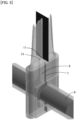
- FIG. 4 is a perspective view of a cartridge according to the first embodiment.
- FIG. 5 is a diagram depicting a result of numerical value analysis of liquids jetted from jetting flow paths formed by the cartridge according to the first embodiment.
- FIG. 6 is a plan sectional view of a liquid-cooled screw compressor according to a comparative example of the present embodiment.
- FIG. 7 is a sectional view along line VII-VII in FIG. 6.
- FIG. 8 is a perspective view of a cartridge according to a second embodiment.
- FIG. 9 is a diagram depicting a result of numerical value analysis of liquids jetted from jetting flow paths formed by the cartridge according to the second embodiment.
- FIG. 10 is a perspective view of a cartridge according to a third embodiment.
- FIG. 11 is a plan view obtained when the cartridge of FIG. 10 is viewed in a direction XI.
- FIG. 12 is a diagram depicting a result of numerical value analysis of liquids jetted from jetting flow paths formed by the cartridge according to the third embodiment.
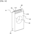
- FIG. 13 is a perspective view of a cartridge according to a fourth embodiment.
Modes for Carrying Out the Invention
-
Embodiments of the present invention are described below with reference to the drawings.
<First Embodiment>
-
A liquid-cooled screw compressor (hereinafter, described also as compressor) 100 according to a first embodiment of the present invention is described with reference to FIGs. 1 to 5. FIG. 1 is a plan sectional view of the compressor 100. FIG. 2 is a sectional view along line II-II in FIG. 1. As depicted in FIGs. 1 and 2, the compressor 100 includes a drive rotor 2 and a driven rotor 3 as a pair of screw rotors that mesh with each other and rotate, and a casing 1 that internally stores the drive rotor 2 and the driven rotor 3 rotatably. The compressor 100 takes in air (gas) and generates compressed air (compressed gas) by rotating the screw rotors 2 and 3.
-
A plurality of helical male teeth are formed in the drive rotor (male rotor) 2. A plurality of helical female teeth are formed in the driven rotor (female rotor) 3. In the casing 1, a bore 8 as a storage chamber that stores the drive rotor 2 and the driven rotor 3 in the state in which they mesh with each other, an intake port that takes in air, and a discharge port that discharges compressed air are formed. A plurality of working spaces (working chambers) C for compressing air are formed by the pair of screw rotors 2 and 3 and the inner wall surface of the bore 8.
-
A prime mover such as an electric motor is connected to the drive rotor 2. When rotational motion of the drive rotor 2 is started by the prime mover, the driven rotor 3 that meshes with the drive rotor 2 also starts rotational motion. This causes air to be sucked into the working spaces C from the intake port. The working spaces C move from the intake port side to the discharge port side in association with the rotation of the screw rotors 2 and 3, and the volume thereof decreases in association with the movement. Due to the decrease in the volume of the working spaces C, the air moves toward the discharge port side while being compressed, and is discharged from the discharge port to the external of the compressor 100.
-
In the liquid-cooled screw compressor 100, a liquid (for example, oil or water) for cooling is injected into the working spaces C in order to suppress a temperature rise of the air due to heat generated by generation of compressed air. The liquid for cooling injected into the working spaces C is used not only for cooling of the air in the working spaces C but also for sealing of gaps between the screw rotors 2, 3 and the inner wall surface of the bore 8, gaps between meshing portions of the drive rotor 2 and the driven rotor 3, and the like, and lubrication of sliding portions of the screw rotors 2 and 3.
-
As depicted in FIG. 2, liquid feed paths 7 that supply the liquid to the working spaces C are formed in the compressor 100. It is to be noted that, although the liquid feed path 7 is made on each of the side of the drive rotor 2 and the side of the driven rotor 3, the liquid feed path 7 on one side is described as a representative in the following because the configuration thereof is the same on both sides.
-
The casing 1 has an introduction path 9 to which the liquid is introduced from the external of the casing 1, a communication path 10 that causes the storage chamber 8 and the introduction path 9 to communicate with each other, and an elongated hole 5 that couples the communication path 10 with the storage chamber 8. As depicted in FIGs. 1 and 2, the elongated hole 5 is an opening extending along the rotation axis direction (hereinafter, also described as axial direction simply) of the screw rotors 2 and 3. In other words, the elongated hole 5 is an opening surface located at the boundary between the communication path 10 and the storage chamber 8, and is formed into a rectangular shape in which the longitudinal direction is the axial direction of the screw rotors 2 and 3 and the short-side direction is the direction (horizontal direction) orthogonal to the axial direction. The elongated hole 5 according to the present embodiment has a pair of long sides opposite to each other and a pair of semi-circular arcs that connect the pair of long sides to each other at both end portions. The elongated hole 5 is formed for each of a male-side bore, which stores the drive rotor 2, in the bore 8 and a female-side bore, which stores the driven rotor 3, in the bore 8.
-
The communication path 10 forms a space with a flattened rectangular parallelepiped shape, and a cartridge 6 with a flattened rectangular parallelepiped shape is disposed in the communication path 10. Due to this, a pair of liquid feed paths 7 are formed by the inner wall surface of the casing 1 and the outer surface of the cartridge 6. The cartridge 6 is attachable and detachable to and from the casing 1.
-
A configuration of the liquid feed path 7 is described in detail with reference to FIGs. 3 and 4. FIG. 3 is an enlarged sectional view of part III in FIG. 2. FIG. 4 is a perspective view of the cartridge 6. As depicted in FIGs. 3 and 4, the cartridge 6 has a rectangular flat plate shape and has a pair of wide width surface portions 62 opposite to each other and a pair of small width surface portions 64 opposite to each other. The wide width surface portion 62 and the small width surface portion 64 are flat surfaces and are orthogonal to each other. The pair of wide width surface portions 62 are parallel to each other, and the pair of small width surface portions 64 are parallel to each other. When the cartridge 6 is disposed in the communication path 10, a base end portion 69 (see FIG. 4) thereof is located on the side of the introduction path 9 and a tip portion 61 thereof is located on the side of the bore 8. That is, the cartridge 6 extends in the vertical direction from the side of the introduction path 9 toward the side of the bore 8 in the communication path 10. The area of the wide width surface portion 62 is larger than the area of each of the base end surface (lower end surface) and the small width surface portion 64 of the cartridge 6. The base end surface of the cartridge 6 is a flat surface orthogonal to each of the wide width surface portions 62 and the small width surface portions 64.
-
In the cartridge 6, a through-hole 66 that penetrates from one wide width surface portion 62 to the other wide width surface portion 62 is formed. The sectional shapes of the through-hole 66 and the introduction path 9 (see FIG. 2) extending in the horizontal direction are circular shapes. It is preferable to set the opening area of the through-hole 66 equal to or larger than the flow path sectional area of the introduction path 9. That is, it is preferable that the diameter of the through-hole 66 be set identical to that of the introduction path 9 or set larger than that of the introduction path 9. The cartridge 6 is disposed in the communication path 10 such that the central axis of the through-hole 66 corresponds with the central axis of the introduction path 9. Due to this, as viewed in the thickness direction of the cartridge 6, the whole of the inner circumferential surface of the introduction path 9 is disposed to fit into the inside of the through-hole 66.
-
The tip portion 61 of the cartridge 6 is formed into a tapered shape having a pair of tapered surface portions 63. That is, in the tip portion 61, the thickness (distance between the tapered surface portions 63 of the pair) becomes smaller toward the tip (top portion 6t) thereof. In the tapered surface portions 63, grooves (recessed portions) 65 are formed from the upper end of the wide width surface portion 62 toward the top portion 6t of the cartridge 6. The top portion 6t is a flat surface parallel to the base end surface of the cartridge 6. The grooves 65 are formed between axial direction end portions 63a located at both ends in the axial direction in the tapered surface portion 63. Bottom surfaces (hereinafter, described also as tapered surfaces) 65a of the grooves 65 are flat surfaces, and are inclined with respect to the wide width surface portions 62 such that the distance between the tapered surfaces 65a of the pair becomes shorter as the position comes closer to the top portion 6t from the wide width surface portions 62. The pair of tapered surfaces 65a are connected to each other by the top portion 6t of the cartridge 6.
-
As depicted in FIG. 3, the communication path 10 is formed with a pair of inclined surface portions 10a opposite to the pair of tapered surface portions 63 of the cartridge 6, a pair of first flow path walls 10b opposite to the pair of wide width surface portions 62, and a pair of second flow path walls (not depicted) opposite to the pair of small width surface portions 64. It is to be noted that step portions 10c may be omitted although being formed between the tapered surface portion 63 and the first flow path wall 10b in the present embodiment. That is, the tapered surface portion 63 may be directly coupled with the first flow path wall 10b.
-
The communication path 10 is formed by causing an endmill having a tapered tip portion of a V-shape to protrude to the inside of the bore (storage chamber) 8 and move in the axial direction of the screw rotors 2 and 3, for example. The length of the elongated hole 5 in the short-side direction can be adjusted by the amount of protrusion of the endmill. Moreover, the length of the elongated hole 5 in the longitudinal direction can be adjusted by the amount of movement of the endmill in the axial direction of the screw rotors 2 and 3. That is, the opening area of the elongated hole 5 is set on the basis of the amount of protrusion and the amount of movement regarding the endmill.
-
When processing is executed by the endmill or the like having the tapered tip portion of the V-shape, a V groove having the pair of inclined surface portions 10a is formed on the upstream side of the elongated hole 5. The tip portion 61 of the cartridge 6 is disposed along this V groove. This forms a pair of jetting flow paths 13 between the V groove of the casing 1 and the tip portion 61 of the cartridge 6.
-
As depicted in FIG. 3, the cartridge 6 and the communication path 10 are formed into a symmetrical shape in the depicted left-right direction. Due to disposing of the cartridge 6 at the center of the communication path 10 in the depicted left-right direction, the space in the communication path 10 is equally divided in the depicted left-right direction by the cartridge 6. That is, the pair of liquid feed paths 7 are formed into a symmetrical shape with the interposition of the cartridge 6 therebetween. The cartridge 6 is disposed such that the top portion (tip) 6t thereof is flush with the inner circumferential surface of the bore (storage chamber) 8. It is to be noted that the top portion 6t of the tip portion 61 of the cartridge 6 may be located on the lower side relative to the lower end surface of the bore 8 in order to surely prevent the tip portion 61 of the cartridge 6 from getting contact with the screw rotors 2 and 3.
-
The pair of liquid feed paths 7 have a pair of supplied liquid retaining spaces 12 that retain the liquid supplied from the introduction path 9 and the pair of jetting flow paths 13 that jet the liquid in the pair of supplied liquid retaining spaces 12 into the working space C.
-
The pair of supplied liquid retaining spaces 12 are formed by the pair of wide width surface portions 62 of the cartridge 6 and the pair of first flow path walls 10b and the pair of second flow path walls (not depicted) forming the inner surface of the communication path 10, through disposing of the cartridge 6 in the communication path 10.
-
The pair of jetting flow paths 13 are formed by the pair of tapered surface portions 63 of the cartridge 6 and the pair of inclined surface portions 10a forming the inner surface of the communication path 10, through disposing of the cartridge 6 in the communication path 10. More specifically, the jetting flow paths 13 having a rectangular flow path section are formed with the grooves 65 of the tapered surface portions 63 and the inclined surface portions 10a by the tapered surfaces of the axial direction end portions 63a of the cartridge 6 being made to abut against the inclined surface portions 10a.
-
The flow path sectional area of the supplied liquid retaining space 12 is larger than that of the jetting flow path 13 to which the liquid is supplied from the supplied liquid retaining space 12. The liquid is introduced from the introduction path 9 made in the horizontal direction to the supplied liquid retaining space 12, and the liquid introduced to the supplied liquid retaining space 12 flows toward the jetting flow path 13 (that is, toward the depicted upper side). Because the flow path sectional area of the supplied liquid retaining space 12 is larger than that of the jetting flow path 13, the speed of the liquid flowing in the supplied liquid retaining space 12 is lower than that of the liquid flowing in the jetting flow path 13. By making the configuration such that the liquid flows in the wide space until reaching the jetting flow path 13 in this manner, the pressure loss can be made as low as possible. Thus, the pressure of the liquid in the jetting flow path 13 can be kept at a high state, and the liquid can be vigorously jetted from the jetting flow path 13.
-
For each of the pair of jetting flow paths 13, a jetting opening 11 facing the working space C is formed by the top portion 6t of the tip portion 61 of the cartridge 6 and the elongated hole 5 of the casing 1. The jetting opening 11 is a rectangular outlet that ejects the liquid from the jetting flow path 13 into the working space C, namely, an opening end surface of the jetting flow path 13, and is exposed to the inside of the bore (storage chamber) 8.
-
The length (opening length) in the axial direction of the screw rotors 2 and 3 in the jetting opening 11 is longer than the length (opening width) in the direction orthogonal to the axial direction. The opening width and the opening length of the jetting opening 11 are set such that the liquid is jetted in a liquid film state from the jetting opening 11. That is, the jetting flow paths 13 according to the first embodiment are liquid film jetting flow paths that jet liquid films. The liquid films jetted from the jetting openings 11 of the pair of jetting flow paths 13 collide with each other in the working space C.
-
The pair of tapered surfaces 65a are formed such that the angle formed by them is equal to or larger than 30 degrees. Moreover, the pair of inclined surface portions 10a are formed such that the angle formed by them is equal to or larger than 30 degrees. The tapered surface 65a and the inclined surface portion 10a are disposed in parallel to each other. The liquid is jetted into the working space C along the tapered surface 65a and the inclined surface portion 10a. That is, the jetting flow paths 13 are formed such that an angle (collision angle) θ formed by the jet directions of the liquids each jetted from the respective jetting flow paths 13, which make the pair, is equal to or larger than 30 degrees.
-
As depicted in FIG. 2, the base end portion 69 of the cartridge 6 is located on the lower side relative to the introduction path 9 extending in the horizontal direction. Although not depicted, the communication path 10 extends to the lower end surface of the casing 1, and an insertion port for inserting the cartridge 6 into the communication path 10 is formed in the lower end surface of the casing 1. It is to be noted that a closing member (not depicted) is mounted in the insertion port and the insertion port is closed by the closing member.
-
FIG. 5 is a diagram depicting a result of numerical value analysis of liquids (liquid films) jetted from the jetting flow paths 13 formed by the cartridge 6. A blacked-out rectangular plane in the diagram is a virtual plane indicating the pressure state of the liquid films, and is not actually disposed for a product.
-
The flow path shape of the pair of jetting flow paths 13 formed by the inclined surface portions 10a of the casing 1 and the grooves 65 of the cartridge 6 is a thin gap shape. Thus, oils are jetted in a liquid film state from the pair of jetting flow paths 13. The thin liquid film jetted from one of the pair of jetting flow paths 13 and the thin liquid film jetted from the other of the pair of jetting flow paths 13 collide with each other in the working space C. By the result of the numerical value analysis, it has been confirmed that turning of the liquid to the thin film is promoted and the surface area of the liquid enlarges due to the collision of the liquids, which are jetted in the liquid film state, with each other. The liquid films that have collided with each other diffuse in a planar manner and are turned to minute particles. This promotes cooling of compressed air in the working space C.
-
As above, in the present embodiment, the space (communication path 10) that can house the cartridge 6 for flow path formation is made on the upstream side of the elongated hole 5 of the casing 1, and the pair of liquid feed paths 7 are formed by disposing the cartridge 6 having a flattened shape in the communication path 10 of the casing 1. The liquid passes through the liquid feed path 7 formed by the outer surface of the cartridge 6 and the casing 1, and is ejected into the working space C. It is to be noted that the present embodiment has the configuration in which the jetting openings 11 extending along the axial direction of the screw rotors 2 and 3 are formed and thin liquid films are jetted from the jetting openings 11.
-
Here, a compressor 900 according to a comparative example of the present embodiment is described with reference to FIGs. 6 and 7. As depicted in FIGs. 6 and 7, in the compressor 900 according to the comparative example of the present embodiment, jetting flow paths 913 are formed by execution of drilled hole processing for the casing 1. The jetting flow paths 913 are small-diameter circular openings that penetrate from an introduction path to the inside of the bore 8. A liquid is jetted into a cylindrical shape from this jetting flow path 913. However, with such a jetting flow path (drilled hole) 913, the liquid does not diffuse, and thus it is difficult to promote cooling.
-
In contrast, in the compressor 100 according to the present embodiment depicted in FIGs. 1 to 5, the length in the axial direction of the screw rotors 2 and 3 in the cartridge 6 and the elongated hole 5 is set long. Thereby, oil in a thin liquid film state is jetted while the amount of supply of the liquid is ensured, and the liquid can be effectively diffused by causing the liquid films to collide with each other. This effectively promotes cooling of compressed air in the working space C.
-
Moreover, in the present embodiment, the grooves 65 are formed in the outer surface of the cartridge 6, and the cartridge 6 is disposed in the communication path 10 formed in the casing 1. Due to this, the jetting flow paths 13 are formed by the casing 1 and the outer surface of the cartridge 6, which is a separate member from the casing 1. Therefore, the present embodiment is excellent in the processability as compared with the configuration in which a plurality of flow paths are formed inside the cartridge 6 in order to increase the flow rate of the liquid as in the technology described in patent document 1 (hereinafter, described also as conventional technology).
-
It is to be noted that the cartridge 6 is attachable and detachable to and from the casing 1. Thus, maintenance such as cleaning of the jetting flow paths 13 can be easily executed by removing the cartridge 6 from the casing 1. In addition, when the operation condition of the compressor 100 is changed, the liquid feed paths 7 that match the operation condition after the change can be formed by changing the cartridge 6 attached to the casing 1.
-
The above-described embodiment provides the following operation and effect.
-
- (1) The compressor 100 is a liquid-cooled screw compressor that takes in air (gas) and generates compressed air (compressed gas). The compressor 100 includes the screw rotors 2 and 3, the casing 1 that stores the screw rotors 2 and 3 and forms the working spaces C together with the screw rotors 2 and 3, and the cartridge 6 that is a separate member from the casing 1. The liquid feed paths 7 that supply a liquid to the working space C are formed by the casing 1 and the outer surface of the cartridge 6.
In this configuration, by processing for the outer shape of the cartridge 6, the amount of liquid (cooling medium) supplied into the working space C can be adjusted, and insufficiency of the liquid can be prevented. Therefore, according to the present embodiment, it is possible to provide the compressor 100 that is excellent in the processability and the maintenance performance of the liquid feed paths 7 and can easily achieve improvement in the cooling performance for air (gas) in the working spaces C. It is to be noted that the processing cost can be suppressed as compared with the case of forming the liquid feed path 7 inside the cartridge 6 because the shape of the liquid feed path 7 can be decided by processing for the outer shape of the cartridge 6 as described above. As a result, the manufacturing cost of the compressor 100 can be suppressed.
- (2) The casing 1 has the bore (storage chamber) 8 that stores the screw rotors 2 and 3, the introduction path 9 to which the liquid is introduced from the external of the casing 1, and the communication path 10 that causes the bore 8 and the introduction path 9 to communicate with each other. The pair of jetting flow paths 13 are formed by the tip portion 61 of the cartridge 6 and the inner surface of the communication path 10 through disposing of the cartridge 6 in the communication path 10. The liquids jetted from the pair of jetting flow paths 13 collide with each other in the working space C.
According to this configuration, by causing the liquids jetted from the pair of jetting flow paths 13 to collide with each other, the liquid turned to minute particles can be diffused in a wide range in the working space C. This can improve the cooling performance for the air in the working space C as compared with the case in which jetted liquids are not caused to collide with each other (see FIGs. 6 and 7).
- (3) As the jetting flow paths 13 according to the present embodiment, only one pair of jetting flow paths 13 are formed by the pair of tapered surface portions 63 and the pair of inclined surface portions 10a through disposing of the cartridge 6 in the communication path 10. The grooves 65 that can jet the liquid (cooling medium) in a liquid film state are formed in the tapered surface portions 63. That is, the jetting flow paths 13 according to the present embodiment are liquid film jetting flow paths that jet liquid films. The liquid films jetted from the pair of jetting flow paths (liquid film jetting flow paths) 13 collide with each other in the working space C.
According to this configuration, turning of the liquid to the thin film is promoted by the collision of the liquid films with each other. In addition, the liquid turned to minute particles can be diffused in a wide range. Due to the turning of the liquid to the thin film and to the minute particles, the surface area (that is, heat exchange area) of the liquid becomes large. Thus, the compressed air in the working spaces C can be effectively cooled and the compressor performance can be improved.
- (4) The pair of liquid feed paths 7 have the pair of supplied liquid retaining spaces 12 that retain the liquid supplied from the introduction path 9, and the pair of jetting flow paths 13 that jet the liquid in the supplied liquid retaining spaces 12 into the working space C. The pair of supplied liquid retaining spaces 12 are formed by the pair of wide width surface portions 62 of the cartridge 6 and the inner surface of the communication path 10. The pair of jetting flow paths 13 are formed by the pair of tapered surface portions 63 of the cartridge 6 and the pair of inclined surface portions 10a of the communication path 10. The flow path sectional area of the pair of supplied liquid retaining spaces 12 formed on the upstream side of the pair of jetting flow paths 13 is larger than that of the pair of jetting flow paths 13.
In this configuration, the supplied liquid retaining spaces 12 having a flow path sectional area larger than that of the jetting flow paths 13 are formed from the introduction path 9 to the jetting flow paths 13. Thus, the pressure loss of the liquid flowing in the liquid feed paths 7 can be made low. This can cause the liquid in a high pressure state to jet vigorously from the jetting openings 11 and diffuse in a wider range.
- (5) The pair of liquid feed paths 7 are formed into a symmetrical shape with the interposition of the cartridge 6 therebetween. Due to this, the difference between the pressure of the liquid in the liquid feed path 7 on the upstream side of the pair of liquid feed paths 7 and the pressure of the liquid in the liquid feed path 7 on the downstream side of the pair of liquid feed paths 7 can be made small. Due to this, the speed of the liquid jetted from each of the pair of jetting flow paths 13 becomes almost the same speed. Thus, it is easy to control the collision part between the liquids. In the present embodiment, a liquid film is equally jetted from each of the pair of jetting flow paths 13. Thus, the liquid films after the collision extend straight along the upward direction.
- (6) Moreover, the flow path sectional shape of the introduction path 9 is a circular shape, and the through-hole 66 that is disposed in the introduction path 9 and has a circular shape is formed in the cartridge 6. The opening area of the through-hole 66 is equal to or larger than the flow path sectional area of the introduction path 9. If the opening area of the through-hole 66 is smaller than the flow path sectional area of the introduction path 9, the pressure loss of the liquid that passes through the through-hole 66 becomes higher. As a result, the difference between the pressure of the liquid in the liquid feed path 7 on the upstream side and the pressure of the liquid in the liquid feed path 7 on the downstream side becomes larger. In this case, a difference is generated between the speed of the liquid jetted from one of the pair of jetting flow paths 13 and the speed of the liquid jetted from the other of the pair of jetting flow paths 13. Therefore, control of the collision part between the liquids becomes difficult. In contrast, in the present embodiment, the opening area of the through-hole 66 disposed in the introduction path 9 is equal to or larger than the flow path sectional area of the introduction path 9. Thus, the pressure loss of the liquid that passes through the through-hole 66 can be suppressed. Due to this, the pressure difference and the speed difference between the liquids each jetted from the respective jetting openings 11 of the pair can be made smaller. Thus, it is easy to control the collision part between the liquids.
- (7) The jetting flow paths 13 are formed such that the angle (collision angle) θ formed by the jet directions of the liquids each jetted from the respective jetting flow paths 13, which make the pair, is equal to or larger than 30 degrees. In the present embodiment, the angle formed by extended lines of the pair of jetting flow paths 13 is equal to or larger than 30 degrees. In this configuration, the liquid can be effectively turned to minute particles and the surface area of the liquid can be enlarged as compared with the case in which the liquids are caused to collide with each other at the collision angle θ smaller than 30 degrees.
- (8) The communication path 10 is coupled with the bore 8 by the elongated hole 5 extending along the axial direction of the screw rotors 2 and 3. For each of the pair of jetting flow paths 13, the jetting opening 11 facing the working space C is formed by the tip portion 61 of the cartridge 6 and the elongated hole 5. According to this configuration, the shape and the opening area of the jetting openings 11 can be adjusted by adjusting the shape of the elongated hole 5 and the shape of the tip portion 61 of the cartridge 6.
<Second Embodiment>
-
A cartridge 6B according to a second embodiment of the present invention is described with reference to FIGs. 8 to 9. It is to be noted that a configuration that is the same as or equivalent to the configuration described in the first embodiment is given the same reference numeral and differences are mainly described. FIG. 8 is a perspective view of the cartridge 6B according to the second embodiment. FIG. 9 is a diagram similar to FIG. 5, and is a diagram depicting a result of numerical value analysis of liquids jetted from jetting flow paths 13B formed by the cartridge 6B according to the second embodiment.
-
Although the casing 1 according to the second embodiment is similar to that of the first embodiment, the cartridge 6B according to the second embodiment is different from the cartridge 6 described in the first embodiment. In the first embodiment, one groove 65 is formed in each of the pair of tapered surface portions 63 (see FIGs. 3 and 4). In contrast, in the second embodiment, as depicted in FIG. 8, a plurality of grooves 67B extending in a straight line manner from the wide width surface portion 62 to a top portion (tip) 6Bt of the tip portion 61 are formed in each of a pair of tapered surface portions 63B. The plurality of grooves 67B are arranged along the axial direction of the screw rotors 2 and 3. The plurality of grooves 67B are each formed along the direction orthogonal to the axial direction of the screw rotors 2 and 3.
-
Moreover, in the first embodiment, the description has been given of the example in which only one pair of jetting flow paths 13 are formed with respect to one cartridge 6 by the pair of tapered surface portions 63 and the pair of inclined surface portions 10a through disposing of the cartridge 6 in the communication path 10 (see FIGs. 3 and 4). In contrast, in the second embodiment, through disposing of the cartridge 6B in the communication path 10, a plurality of pairs (in the depicted example, six pairs) of jetting flow paths 13B are formed, with respect to one cartridge 6B, by the plurality of grooves 67B of the pair of tapered surface portions 63B and the pair of inclined surface portions 10a.
-
Moreover, the jetting flow paths 13 according to the first embodiment are liquid film jetting flow paths that jet liquid films. In contrast, the jetting flow paths 13B according to the present second embodiment are jet flow jetting flow paths that jet jet flows. For each of the plurality of pairs of jetting flow paths 13B, a jetting opening 11B facing the working space C is formed by the top portion 6Bt of the tip portion 61 of the cartridge 6B and the elongated hole 5.
-
The jet flows jetted from the plurality of pairs of jet flow jetting flow paths 13B collide with each other in the working space C.
-
In addition, similarly to the first embodiment, the sum of the flow path sectional areas of the pair of supplied liquid retaining spaces 12 is larger than that of the flow path sectional areas of the plurality of pairs of jetting flow paths 13.
-
In the present second embodiment, the plurality of pairs of jetting flow paths (jet flow jetting flow paths) 13B are formed by the casing 1 and the outer surface of the cartridge 6B. The jet flows each jetted from the respective jetting flow paths 13B, which make the pair, collide with each other in the working space C. According to the present second embodiment, as depicted in FIG. 9, due to the collision of the jet flows with each other, the liquid spreads into a fan shape in the axial direction of the screw rotors 2 and 3, and the surface area of the liquid enlarges. Therefore, according to the present second embodiment, similarly to the first embodiment, it is possible to provide the compressor 100 that is excellent in the processability and the maintenance performance of the liquid feed paths 7, and can easily achieve improvement in the cooling performance for air (gas) in the working spaces C.
<Third Embodiment>
-
A cartridge 6C according to a third embodiment of the present invention is described with reference to FIGs. 10 to 12. It is to be noted that a configuration that is the same as or equivalent to the configuration described in the second embodiment is given the same reference numeral, and differences are mainly described. FIG. 10 is a perspective view of the cartridge 6C according to the third embodiment. FIG. 11 is a plan view obtained when the cartridge 6C of FIG. 10 is viewed in an XI direction. FIG. 12 is a diagram similar to those in FIGs. 5 and 9, and is a diagram depicting a result of numerical value analysis of liquids jetted from jetting flow paths 13C formed by the cartridge 6C according to the third embodiment.
-
In the second embodiment, the plurality of grooves 67B of the tapered surface portions 63B are formed along the direction orthogonal to the axial direction of the screw rotors 2 and 3 (see FIG. 8). In contrast, in the third embodiment, as depicted in FIGs. 10 and 11, a plurality of grooves 67C of tapered surface portions 63C are formed along a direction inclined with respect to each of the axial direction of the screw rotors 2 and 3 and the direction orthogonal to the axial direction.
-
As depicted in FIG. 11, in the third embodiment, in plan view, an extension direction D1 of the grooves 67C intersects each of an axial direction D0 of the screw rotors 2 and 3 and the direction orthogonal to the axial direction D0 (plane orthogonal to the axial direction D0).
-
In the third embodiment, similarly to the second embodiment, a plurality of pairs of jetting flow paths (jet flow jetting flow paths) 13C are formed by the casing 1 and the outer surface of the cartridge 6C. Thus, operation and effect similar to those of the second embodiment are provided. Moreover, in the present third embodiment, the jetting flow paths 13C are obliquely formed with respect to the axial direction D0 and the direction orthogonal to the axial direction D0 in plan view. Therefore, as depicted in FIGs. 11 and 12, due to the collision of jet flows with each other, the liquid spreads into a fan shape in the direction orthogonal to the extension direction D1 of the grooves 67C and the surface area of the liquid enlarges. According to such a third embodiment, by adjusting an angle (in plan view, angle formed by the axial direction D0 and the extension direction D1 of the grooves 67C) φ of the plurality of grooves 67, the liquids that have been jetted from the jetting flow paths 13C, which make the pair, and then collided with each other can be diffused in the direction along the tooth groove of the screw rotors 2 and 3 or be diffused toward a section of the tooth groove.
<Fourth Embodiment>
-
A cartridge 6D according to a fourth embodiment of the present invention is described with reference to FIG. 13. It is to be noted that a configuration that is the same as or equivalent to the configuration described in the third embodiment is given the same reference numeral, and differences are mainly described. FIG. 13 is a perspective view of the cartridge 6D according to the fourth embodiment.
-
The present fourth embodiment is different from the third embodiment in that a groove 68 extending in the axial direction of the screw rotors 2 and 3 is formed at a top portion (tip) of the tip portion 61 of the cartridge 6D. The groove 68 is formed to enlarge the range of liquid feed to the inside of the working space C. In the present embodiment, the groove 68 is formed into a sectional V-shape that hollows from the tip side of the tip portion 61 toward the base end side.
-
In the third embodiment, as depicted in FIG. 10, the configuration in which jetting openings 11C are opened in the upper surface is made, and the pair of jetting flow paths 13C are separated by a partition wall. In contrast, in the present fourth embodiment, as depicted in FIG. 13, jetting openings 11D are formed in the groove 68 of the V-shape, and a space is made between the jetting openings 11D, which make the pair. In the third embodiment, there is a possibility that diffusion is inhibited by the partition wall in the groove 67C immediately before jetting depending on the diffusion condition after the jet flow collision. In contrast, with the cartridge 6D according to the present fourth embodiment, due to the formation of the groove 68 of the V-shape at the tip of the tip portion 61, the partition wall in the groove 67D immediately before jetting does not exist and the inhibition of diffusion after the collision of jet flows with each other is suppressed. That is, according to the present fourth embodiment, the liquid can be diffused in a wide range as compared with the third embodiment.
-
As above, in the compressors according to the first to fourth embodiments, one or more pairs of jetting flow paths that can cause jetted liquids to collide with each other are formed by combining the casing and the outer surface of the cartridge. Thus, by only changing the content of processing and the length in the longitudinal direction (axial direction of the screw rotors 2 and 3) regarding one cartridge disposed for one screw rotor, the cooling performance in the working spaces C can be enhanced and the flow rate of the liquid used for cooling of compressed air can be easily changed.
<Other Embodiments>
-
It is to be noted that the present invention is not limited to the above-described embodiments and various modifications are included therein. The above-described embodiments are described in detail in order to explain the present invention in an easy-to-understand manner and are not necessarily limited to that including all configurations described. That is, it is possible to replace part of a configuration of a certain embodiment by a configuration of another embodiment. Moreover, it is also possible to add a configuration of a certain embodiment to a configuration of another embodiment. In addition, it is also possible to execute addition, deletion, or substitution of another configuration regarding part of configurations of the respective embodiments.
-
It is to be noted that, although the description has been given by taking the liquid-cooled screw compressor of a twin-rotor type as an example in the above-described embodiments, it is also possible to apply the present invention to screw compressors other than the twin-rotor type, such as a single-rotor type and a triple-rotor type. Moreover, the gas compressed by the compressor is not limited to the air.
Description of Reference Characters
-
- 1: Casing
- 2: Drive rotor (screw rotor)
- 3: Driven rotor (screw rotor)
- 5: Elongated hole
- 6, 6B, 6C, 6D: Cartridge
- 6t, 6Bt, 6Dt: Top portion (tip)
- 7: Liquid feed path
- 8: Bore (storage chamber)
- 9: Introduction path
- 10: Communication path
- 10a: Inclined surface portion
- 10b: First flow path wall
- 10c: Step portion
- 11, 11C, 11D: Jetting opening
- 12: Supplied liquid retaining space
- 13: Jetting flow path (liquid film jetting flow path)
- 13B: Jetting flow path (jet flow jetting flow path)
- 13C: Jetting flow path (jet flow jetting flow path)
- 61: Tip portion
- 62: Wide width surface portion
- 63, 63B, 63C: Tapered surface portion
- 63a: Axial direction end portion
- 64: Small width surface portion
- 65: Groove (recessed portion)
- 65a: Bottom surface (tapered surface)
- 66: Through-hole
- 67, 67B, 67C, 67D: Groove
- 68: Groove
- 69: Base end portion
- 100: Compressor (liquid-cooled screw compressor)
- C: Working space (working chamber)
- θ: Collision angle