EP4563806A2 - Wingletejektorkonfigurationen - Google Patents
Wingletejektorkonfigurationen Download PDFInfo
- Publication number
- EP4563806A2 EP4563806A2 EP25151184.6A EP25151184A EP4563806A2 EP 4563806 A2 EP4563806 A2 EP 4563806A2 EP 25151184 A EP25151184 A EP 25151184A EP 4563806 A2 EP4563806 A2 EP 4563806A2
- Authority
- EP
- European Patent Office
- Prior art keywords
- vehicle
- coupled
- diffusing structure
- convex surface
- airfoil
- Prior art date
- Legal status (The legal status is an assumption and is not a legal conclusion. Google has not performed a legal analysis and makes no representation as to the accuracy of the status listed.)
- Pending
Links
Images

Classifications
-
- B—PERFORMING OPERATIONS; TRANSPORTING
- B64—AIRCRAFT; AVIATION; COSMONAUTICS
- B64C—AEROPLANES; HELICOPTERS
- B64C9/00—Adjustable control surfaces or members, e.g. rudders
- B64C9/38—Jet flaps
-
- B—PERFORMING OPERATIONS; TRANSPORTING
- B64—AIRCRAFT; AVIATION; COSMONAUTICS
- B64D—EQUIPMENT FOR FITTING IN OR TO AIRCRAFT; FLIGHT SUITS; PARACHUTES; ARRANGEMENT OR MOUNTING OF POWER PLANTS OR PROPULSION TRANSMISSIONS IN AIRCRAFT
- B64D33/00—Arrangement in aircraft of power plant parts or auxiliaries not otherwise provided for
- B64D33/04—Arrangement in aircraft of power plant parts or auxiliaries not otherwise provided for of exhaust outlets or jet pipes
-
- B—PERFORMING OPERATIONS; TRANSPORTING
- B64—AIRCRAFT; AVIATION; COSMONAUTICS
- B64C—AEROPLANES; HELICOPTERS
- B64C15/00—Attitude, flight direction, or altitude control by jet reaction
- B64C15/02—Attitude, flight direction, or altitude control by jet reaction the jets being propulsion jets
-
- B—PERFORMING OPERATIONS; TRANSPORTING
- B64—AIRCRAFT; AVIATION; COSMONAUTICS
- B64C—AEROPLANES; HELICOPTERS
- B64C29/00—Aircraft capable of landing or taking-off vertically, e.g. vertical take-off and landing [VTOL] aircraft
- B64C29/0008—Aircraft capable of landing or taking-off vertically, e.g. vertical take-off and landing [VTOL] aircraft having its flight directional axis horizontal when grounded
- B64C29/0041—Aircraft capable of landing or taking-off vertically, e.g. vertical take-off and landing [VTOL] aircraft having its flight directional axis horizontal when grounded the lift during taking-off being created by jet motors
-
- B—PERFORMING OPERATIONS; TRANSPORTING
- B64—AIRCRAFT; AVIATION; COSMONAUTICS
- B64C—AEROPLANES; HELICOPTERS
- B64C3/00—Wings
- B64C3/10—Shape of wings
- B64C3/14—Aerofoil profile
- B64C3/141—Circulation Control Airfoils
-
- F—MECHANICAL ENGINEERING; LIGHTING; HEATING; WEAPONS; BLASTING
- F02—COMBUSTION ENGINES; HOT-GAS OR COMBUSTION-PRODUCT ENGINE PLANTS
- F02K—JET-PROPULSION PLANTS
- F02K1/00—Plants characterised by the form or arrangement of the jet pipe or nozzle; Jet pipes or nozzles peculiar thereto
- F02K1/36—Plants characterised by the form or arrangement of the jet pipe or nozzle; Jet pipes or nozzles peculiar thereto having an ejector
-
- F—MECHANICAL ENGINEERING; LIGHTING; HEATING; WEAPONS; BLASTING
- F02—COMBUSTION ENGINES; HOT-GAS OR COMBUSTION-PRODUCT ENGINE PLANTS
- F02K—JET-PROPULSION PLANTS
- F02K7/00—Plants in which the working fluid is used in a jet only, i.e. the plants not having a turbine or other engine driving a compressor or a ducted fan; Control thereof
- F02K7/08—Plants in which the working fluid is used in a jet only, i.e. the plants not having a turbine or other engine driving a compressor or a ducted fan; Control thereof the jet being continuous
-
- F—MECHANICAL ENGINEERING; LIGHTING; HEATING; WEAPONS; BLASTING
- F05—INDEXING SCHEMES RELATING TO ENGINES OR PUMPS IN VARIOUS SUBCLASSES OF CLASSES F01-F04
- F05D—INDEXING SCHEME FOR ASPECTS RELATING TO NON-POSITIVE-DISPLACEMENT MACHINES OR ENGINES, GAS-TURBINES OR JET-PROPULSION PLANTS
- F05D2270/00—Control
- F05D2270/01—Purpose of the control system
- F05D2270/17—Purpose of the control system to control boundary layer
- F05D2270/173—Purpose of the control system to control boundary layer by the Coanda effect
Definitions
- VTOL Vertical Take-Off and Landing
- STOL Short Take-Off and Landing
- an example of a current aircraft that has VTOL capability is the F-35 Lightning.
- Conventional methods of vectoring the vertical lift airflow includes the use of nozzles that can be swiveled in a single direction along with the use of two sets of flat flapper vanes arranged 90 degrees to each other and located at the external nozzle.
- the propulsion system of the F-35 Lightning similarly, provides vertical lifting force using a combination of vectored thrust from the turbine engine and a vertically oriented lift fan.
- the lift fan is located behind the cockpit in a bay with upper and lower clamshell doors.
- the engine exhausts through a three-bearing swivel nozzle that can deflect the thrust from horizontal to just forward of vertical.
- Roll control ducts extend out in each wing and are supplied with their thrust with air from the engine fan. Pitch control is affected via lift fan/engine thrust split. Yaw control is through yaw motion of the engine swivel nozzle. Roll control is provided by differentially opening and closing the apertures at the ends of the two roll control ducts.
- the lift fan has a telescoping "D"-shaped nozzle to provide thrust deflection in the forward and aft directions.
- the D-nozzle has fixed vanes at the exit aperture.
- the design of an aircraft or drone more generally consists of its propulsive elements and the airframe into which those elements are integrated.
- the propulsive device in aircrafts can be a turbojet, turbofan, turboprop or turboshaft, piston engine, or an electric motor equipped with a propeller.
- the propulsive system (propulsor) in small unmanned aerial vehicles (UAVs) is conventionally a piston engine or an electric motor which provides power via a shaft to one or several propellers.
- the propulsor for a larger aircraft, whether manned or unmanned, is traditionally a jet engine or a turboprop.
- the propulsor is generally attached to the fuselage or the body or the wings of the aircraft via pylons or struts capable of transmitting the force to the aircraft and sustaining the loads.
- the emerging mixed jet (jet efflux) of air and gases is what propels the aircraft in the opposite direction to the flow of the jet efflux.
- the air stream efflux of a large propeller is not used for lift purposes in level flight and a significant amount of kinetic energy is hence not utilized to the benefit of the aircraft, unless it is swiveled as in some of the applications existing today (namely the Bell Boeing V-22 Osprey). Rather, the lift on most existing aircrafts is created by the wings and tail. Moreover, even in those particular VTOL applications (e.g., take-off through the transition to level flight) found in the Osprey, the lift caused by the propeller itself is minimal during level flight, and most of the lift force is nonetheless from the wings.
- VTOL applications e.g., take-off through the transition to level flight
- Airfoils are characterized by a chord line extended mainly in the axial direction, from a leading edge to a trailing edge of the airfoil. Based on the angle of attack formed between the incident airflow and the chord line, and according to the principles of airfoil lift generation, lower pressure air is flowing over the suction (upper) side and conversely, by Bernoulli law, moving at higher speeds than the lower side (pressure side).
- a similar vehicle using jet fuel or any other hydrocarbon fuel typically used in transportation will carry more usable fuel by at least one order of magnitude. This can be explained by the much higher energy density of the hydrocarbon fuel compared to battery systems (by at least one order of magnitude), as well as the lower weight to total vehicle weight ratio of a hydrocarbon fuel based system.
- One embodiment of the present invention includes a propulsor that utilizes fluidics for the entrainment and acceleration of ambient air and delivers a high-speed jet efflux of a mixture of the high-pressure gas (supplied to the propulsor from a gas generator) and entrained ambient air.
- this objective is achieved by discharging the gas adjacent to a convex surface.
- the convex surface is a so-called Coanda surface benefitting from the Coanda effect described in U.S. Pat. No. 2,052,869 issued to Henri Coanda on Sep. 1, 1936 .
- the Coanda effect is the tendency of a jet-emitted gas or liquid to travel close to a wall contour even if the direction of curvature of the wall is away from the axis of the jet.
- the convex Coanda surfaces discussed herein with respect to one or more embodiments do not have to consist of any particular material.
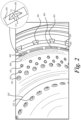
- FIG. 1 illustrates a cross-section of the upper half of an ejector 200 that may be attached to a vehicle (not shown), such as, for non-limiting examples, a UAV or a manned aerial vehicle, such as an airplane.
- a duct such as plenum 211, is supplied with hotter-than-ambient air (i.e., a pressurized motive gas stream) from, for example, a combustion-based engine that may be employed by the vehicle.
- This pressurized motive gas stream denoted by arrow 600, is introduced via at least one conduit, such as primary nozzles 203, to the interior of the ejector 200.
- the primary nozzles 203 are configured to accelerate the motive fluid stream 600 to a variable predetermined desired velocity directly over a convex Coanda surface 204 as a wall jet. Additionally, primary nozzles 203 provide adjustable volumes of fluid stream 600. This wall jet, in turn, serves to entrain through an intake structure 206 secondary fluid, such as ambient air denoted by arrow 1, that may be at rest or approaching the ejector 200 at non-zero speed from the direction indicated by arrow 1. In various embodiments, the nozzles 203 may be arranged in an array and in a curved orientation, a spiraled orientation, and/or a zigzagged orientation.
- the mix of the stream 600 and the air 1 may be moving purely axially at a throat section 225 of the ejector 200.
- a diffusing structure such as diffuser 210
- the mixing and smoothing out process continues so the profiles of temperature (800) and velocity (700) in the axial direction of ejector 200 no longer have the high and low values present at the throat section 225, but become more uniform at the terminal end 100 of diffuser 210.
- the temperature and velocity profiles are almost uniform.
- the temperature of the mixture is low enough to be directed towards an airfoil such as a wing or control surface.
- V-shaped, vortex generating secondary nozzles 205 are staggered when compared to a normal rectangular primary nozzle 203 and injecting at least 25% of the total fluid stream 600 before the balance of the fluid stream massflow is injected at a moment later by nozzles 203.
- This injection by nozzles 205 prior to that of nozzles 203 results in a higher entrainment rate enough to significantly increase the performance of the ejector 200.
- Secondary nozzles 205 introduce a more-favorable entrainment of the secondary flow via shear layers and are staggered both axially and circumferentially in relation to the primary nozzles 203.
- Primary nozzles 203 may include an airfoil, such as a delta-wing structure 226, that is provided with a supporting leg 227 connected to the middle point of the primary nozzle 203 structure at its innermost side, with a delta-wing structure apex pointing against the fluid stream 600 flow to maximize entrainment. This in turn generates two vortices opposed in direction towards the center of the delta wing 226 and strongly entraining from both sides of primary nozzle 203 the already entrained mixture of primary and secondary fluid flows resulting from nozzles 205.
- Supporting leg 227 may, in an embodiment, serve as an actuating element capable of causing structure 226 to vibrate.
- an embodiment improves the surface for flow separation delay via elements such as dimples 221 placed on the Coanda surface 204.
- the dimples 221 prevent separation of the flow and enhance the performance of the ejector 200 significantly.
- surfaces of the diffuser 210 may also include dimples 222 and/or other elements that delay or prevent separation of the boundary layer.
- FIG. 226 may depict structures different from delta wing 226 to enhance entrainment and the attachment of the flow produced through nozzles 203.
- thermophoresis in which a cold fluid is made available to cool off surface 204 where the separation propensity at high speeds is greater. By cooling off several regions of the surface 204, the hot motive fluid is diverted towards the cold portion of surface 204 through the force of thermophoresis.
- bleed air from the compressor discharge of a jet engine acting as a gas generator is routed towards an internal channel system (not shown) of ejector 200 that allows the cooling of hot spots where separation occurs.
- a typical difference in temperature goes from 100 F uncooled to 500F (hot stream temperature of a nozzle 203 is 1200 and wall temperature is brought down to 700F).
- Another approach may employ electrophoresis in which elements (not shown) embedded into surface 204 generate a local field that enhances fluid attachment and delays or eliminates separation.
- the current source for such elements can be provided by a battery or a generator coupled with the main gas generator of the vehicle.
- Another approach may employ plasma in a manner similar to electrophoresis as in the use of electric fields, albeit in this case acting at high altitudes where plasma generation is less energy-intensive. Specially placed elements (not shown) may enhance attachment and eliminate separation.
- Yet another approach may mechanically reduce or enlarge the height of the nozzles 203.
- By reducing the wall height it is possible to increase local velocity. Such may be achieved by curving the inlet portion of the individual channels where the hot flow is guided from the plenum to the nozzles 203 and manipulating the flow in that manner.
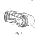
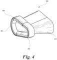
- intake structure 206 may be circular in configuration. However, in varying embodiments, and as best shown in FIGS. 3-4 , intake structure 206 can be non-circular and, indeed, asymmetrical ( i.e ., not identical on both sides of at least one, or alternatively any-given, plane bisecting the intake structure).
- the intake structure 206 can include first and second opposing edges 301, 302, wherein the second opposing edge includes a curved portion projecting toward the first opposing edge.
- the intake structure 206 can include first and second lateral opposing edges 401, 402, wherein the first lateral opposing edge has a greater radius of curvature than the second lateral opposing edge.
Landscapes
- Engineering & Computer Science (AREA)
- Aviation & Aerospace Engineering (AREA)
- Chemical & Material Sciences (AREA)
- Combustion & Propulsion (AREA)
- Mechanical Engineering (AREA)
- General Engineering & Computer Science (AREA)
- Jet Pumps And Other Pumps (AREA)
Applications Claiming Priority (3)
| Application Number | Priority Date | Filing Date | Title |
|---|---|---|---|
| US15/625,907 US20170283080A1 (en) | 2015-09-02 | 2017-06-16 | Winglet ejector configurations |
| EP18817815.6A EP3638587B1 (de) | 2017-06-16 | 2018-06-15 | Wingletejektorkonfigurationen |
| PCT/US2018/037902 WO2018232340A1 (en) | 2017-06-16 | 2018-06-15 | Winglet ejector configurations |
Related Parent Applications (1)
| Application Number | Title | Priority Date | Filing Date |
|---|---|---|---|
| EP18817815.6A Division EP3638587B1 (de) | 2017-06-16 | 2018-06-15 | Wingletejektorkonfigurationen |
Publications (2)
| Publication Number | Publication Date |
|---|---|
| EP4563806A2 true EP4563806A2 (de) | 2025-06-04 |
| EP4563806A3 EP4563806A3 (de) | 2025-07-30 |
Family
ID=64660749
Family Applications (2)
| Application Number | Title | Priority Date | Filing Date |
|---|---|---|---|
| EP18817815.6A Active EP3638587B1 (de) | 2017-06-16 | 2018-06-15 | Wingletejektorkonfigurationen |
| EP25151184.6A Pending EP4563806A3 (de) | 2017-06-16 | 2018-06-15 | Wingletejektorkonfigurationen |
Family Applications Before (1)
| Application Number | Title | Priority Date | Filing Date |
|---|---|---|---|
| EP18817815.6A Active EP3638587B1 (de) | 2017-06-16 | 2018-06-15 | Wingletejektorkonfigurationen |
Country Status (10)
| Country | Link |
|---|---|
| EP (2) | EP3638587B1 (de) |
| JP (1) | JP7217272B2 (de) |
| KR (1) | KR20200056978A (de) |
| CN (2) | CN111655580B (de) |
| BR (1) | BR112019026384B8 (de) |
| CA (1) | CA3067346A1 (de) |
| ES (1) | ES3022937T3 (de) |
| IL (2) | IL315640A (de) |
| MY (1) | MY204828A (de) |
| WO (1) | WO2018232340A1 (de) |
Families Citing this family (1)
| Publication number | Priority date | Publication date | Assignee | Title |
|---|---|---|---|---|
| CN111577657B (zh) * | 2020-04-29 | 2021-10-29 | 南京工业大学 | 带有无源自激励扫掠射流流动控制装置的压气机叶片 |
Citations (1)
| Publication number | Priority date | Publication date | Assignee | Title |
|---|---|---|---|---|
| US2052869A (en) | 1934-10-08 | 1936-09-01 | Coanda Henri | Device for deflecting a stream of elastic fluid projected into an elastic fluid |
Family Cites Families (19)
| Publication number | Priority date | Publication date | Assignee | Title |
|---|---|---|---|---|
| GB844748A (en) * | 1956-01-11 | 1960-08-17 | English Electric Co Ltd | Improvements in and relating to aircraft wings incorporating a power installation for propulsion |
| US3525474A (en) * | 1968-12-09 | 1970-08-25 | Us Air Force | Jet pump or thrust augmentor |
| US3591087A (en) | 1969-05-08 | 1971-07-06 | Rohr Corp | Apparatus for augmenting the thrust of an aircraft jet engine |
| US3819134A (en) * | 1972-11-30 | 1974-06-25 | Rockwell International Corp | Aircraft system lift ejector |
| JPS5349612A (en) * | 1976-10-14 | 1978-05-06 | Petorobuichi Subuisuc Georugii | Ejector engine thrust increase device |
| DK140426B (da) * | 1976-11-01 | 1979-08-27 | Arborg O J M | Fremdriftsdyse til transportmidler i luft eller vand. |
| CA1100463A (en) * | 1978-11-22 | 1981-05-05 | Frederick L. Gilbertson | Nozzle structure with notches |
| US4413782A (en) * | 1980-12-18 | 1983-11-08 | The United States Of America As Represented By The Secretary Of The Navy | Jet excitation by an oscillating vane |
| US4448354A (en) * | 1982-07-23 | 1984-05-15 | The United States Of America As Represented By The Secretary Of The Air Force | Axisymmetric thrust augmenting ejector with discrete primary air slot nozzles |
| US4815942A (en) * | 1982-10-25 | 1989-03-28 | Elayne P. Alperin | Axially-symmetric, jet-diffuser ejector |
| US4666104A (en) | 1985-07-22 | 1987-05-19 | Kelber Charles C | Combination lift thrust device |
| JP3525527B2 (ja) * | 1994-12-21 | 2004-05-10 | 石川島播磨重工業株式会社 | 航空機エンジンのローブミキサ |
| US20060059891A1 (en) * | 2004-09-23 | 2006-03-23 | Honeywell International, Inc. | Quiet chevron/tab exhaust eductor system |
| US7686257B2 (en) | 2005-05-23 | 2010-03-30 | Lockheed Martin Corporation | Dual bimorph synthetic pulsator |
| US7937945B2 (en) * | 2006-10-27 | 2011-05-10 | Kinde Sr Ronald August | Combining a series of more efficient engines into a unit, or modular units |
| US20160152324A1 (en) | 2013-04-01 | 2016-06-02 | California Institute Of Technology | Fluidic fence for performance enhancement |
| US9587585B1 (en) * | 2013-04-30 | 2017-03-07 | The United States Of America As Represented By The Secretary Of The Air Force | Augmented propulsion system with boundary layer suction and wake blowing |
| CA2996285C (en) | 2015-09-02 | 2023-10-31 | Jetoptera, Inc. | Ejector and airfoil configurations |
| US20170283080A1 (en) * | 2015-09-02 | 2017-10-05 | Jetoptera, Inc. | Winglet ejector configurations |
-
2018
- 2018-06-15 CA CA3067346A patent/CA3067346A1/en active Pending
- 2018-06-15 CN CN201880047603.3A patent/CN111655580B/zh active Active
- 2018-06-15 MY MYPI2019007491A patent/MY204828A/en unknown
- 2018-06-15 KR KR1020207001412A patent/KR20200056978A/ko not_active Ceased
- 2018-06-15 ES ES18817815T patent/ES3022937T3/es active Active
- 2018-06-15 BR BR112019026384A patent/BR112019026384B8/pt active IP Right Grant
- 2018-06-15 EP EP18817815.6A patent/EP3638587B1/de active Active
- 2018-06-15 WO PCT/US2018/037902 patent/WO2018232340A1/en not_active Ceased
- 2018-06-15 IL IL315640A patent/IL315640A/en unknown
- 2018-06-15 CN CN202410029899.3A patent/CN118205703A/zh active Pending
- 2018-06-15 EP EP25151184.6A patent/EP4563806A3/de active Pending
- 2018-06-15 IL IL271437A patent/IL271437B2/en unknown
- 2018-06-15 JP JP2020519014A patent/JP7217272B2/ja active Active
Patent Citations (1)
| Publication number | Priority date | Publication date | Assignee | Title |
|---|---|---|---|---|
| US2052869A (en) | 1934-10-08 | 1936-09-01 | Coanda Henri | Device for deflecting a stream of elastic fluid projected into an elastic fluid |
Also Published As
| Publication number | Publication date |
|---|---|
| BR112019026384B8 (pt) | 2024-02-06 |
| EP3638587A1 (de) | 2020-04-22 |
| ES3022937T3 (en) | 2025-05-29 |
| EP3638587B1 (de) | 2025-01-15 |
| JP7217272B2 (ja) | 2023-02-02 |
| WO2018232340A1 (en) | 2018-12-20 |
| EP4563806A3 (de) | 2025-07-30 |
| EP3638587A4 (de) | 2021-03-24 |
| BR112019026384A2 (pt) | 2020-07-21 |
| JP2020524116A (ja) | 2020-08-13 |
| KR20200056978A (ko) | 2020-05-25 |
| IL315640A (en) | 2024-11-01 |
| CN111655580B (zh) | 2024-01-16 |
| CN111655580A (zh) | 2020-09-11 |
| MY204828A (en) | 2024-09-18 |
| BR112019026384B1 (pt) | 2023-12-12 |
| IL271437A (en) | 2020-01-30 |
| CN118205703A (zh) | 2024-06-18 |
| IL271437B2 (en) | 2025-02-01 |
| IL271437B1 (en) | 2024-10-01 |
| CA3067346A1 (en) | 2018-12-20 |
Similar Documents
| Publication | Publication Date | Title |
|---|---|---|
| US12545423B2 (en) | Fluidic propulsive system | |
| US11053012B2 (en) | Winglet ejector configurations | |
| EP3638587B1 (de) | Wingletejektorkonfigurationen |
Legal Events
| Date | Code | Title | Description |
|---|---|---|---|
| PUAI | Public reference made under article 153(3) epc to a published international application that has entered the european phase |
Free format text: ORIGINAL CODE: 0009012 |
|
| STAA | Information on the status of an ep patent application or granted ep patent |
Free format text: STATUS: THE APPLICATION HAS BEEN PUBLISHED |
|
| AC | Divisional application: reference to earlier application |
Ref document number: 3638587 Country of ref document: EP Kind code of ref document: P |
|
| AK | Designated contracting states |
Kind code of ref document: A2 Designated state(s): AL AT BE BG CH CY CZ DE DK EE ES FI FR GB GR HR HU IE IS IT LI LT LU LV MC MK MT NL NO PL PT RO RS SE SI SK SM TR |
|
| REG | Reference to a national code |
Ref country code: DE Ref legal event code: R079 Free format text: PREVIOUS MAIN CLASS: F02K0001360000 Ipc: B64D0033040000 |
|
| PUAL | Search report despatched |
Free format text: ORIGINAL CODE: 0009013 |
|
| AK | Designated contracting states |
Kind code of ref document: A3 Designated state(s): AL AT BE BG CH CY CZ DE DK EE ES FI FR GB GR HR HU IE IS IT LI LT LU LV MC MK MT NL NO PL PT RO RS SE SI SK SM TR |
|
| RIC1 | Information provided on ipc code assigned before grant |
Ipc: B64D 33/04 20060101AFI20250626BHEP Ipc: F02K 1/36 20060101ALI20250626BHEP |
|
| STAA | Information on the status of an ep patent application or granted ep patent |
Free format text: STATUS: REQUEST FOR EXAMINATION WAS MADE |
|
| 17P | Request for examination filed |
Effective date: 20260126 |