EP4563779A1 - Force assist arrangement and automobile equipped therewith - Google Patents
Force assist arrangement and automobile equipped therewith Download PDFInfo
- Publication number
- EP4563779A1 EP4563779A1 EP23213809.9A EP23213809A EP4563779A1 EP 4563779 A1 EP4563779 A1 EP 4563779A1 EP 23213809 A EP23213809 A EP 23213809A EP 4563779 A1 EP4563779 A1 EP 4563779A1
- Authority
- EP
- European Patent Office
- Prior art keywords
- rope
- flap
- arrangement
- force assist
- spring
- Prior art date
- Legal status (The legal status is an assumption and is not a legal conclusion. Google has not performed a legal analysis and makes no representation as to the accuracy of the status listed.)
- Granted
Links
Images

Classifications
-
- E—FIXED CONSTRUCTIONS
- E05—LOCKS; KEYS; WINDOW OR DOOR FITTINGS; SAFES
- E05F—DEVICES FOR MOVING WINGS INTO OPEN OR CLOSED POSITION; CHECKS FOR WINGS; WING FITTINGS NOT OTHERWISE PROVIDED FOR, CONCERNED WITH THE FUNCTIONING OF THE WING
- E05F1/00—Closers or openers for wings, not otherwise provided for in this subclass
- E05F1/08—Closers or openers for wings, not otherwise provided for in this subclass spring-actuated, e.g. for horizontally sliding wings
- E05F1/10—Closers or openers for wings, not otherwise provided for in this subclass spring-actuated, e.g. for horizontally sliding wings for swinging wings, e.g. counterbalance
- E05F1/1008—Closers or openers for wings, not otherwise provided for in this subclass spring-actuated, e.g. for horizontally sliding wings for swinging wings, e.g. counterbalance with a coil spring parallel with the pivot axis
- E05F1/1016—Closers or openers for wings, not otherwise provided for in this subclass spring-actuated, e.g. for horizontally sliding wings for swinging wings, e.g. counterbalance with a coil spring parallel with the pivot axis with a canted-coil torsion spring
-
- E—FIXED CONSTRUCTIONS
- E05—LOCKS; KEYS; WINDOW OR DOOR FITTINGS; SAFES
- E05D—HINGES OR SUSPENSION DEVICES FOR DOORS, WINDOWS OR WINGS
- E05D7/00—Hinges or pivots of special construction
- E05D7/08—Hinges or pivots of special construction for use in suspensions comprising two spigots placed at opposite edges of the wing, especially at the top and the bottom, e.g. trunnions
- E05D7/081—Hinges or pivots of special construction for use in suspensions comprising two spigots placed at opposite edges of the wing, especially at the top and the bottom, e.g. trunnions the pivot axis of the wing being situated near one edge of the wing, especially at the top and bottom, e.g. trunnions
-
- E—FIXED CONSTRUCTIONS
- E05—LOCKS; KEYS; WINDOW OR DOOR FITTINGS; SAFES
- E05Y—INDEXING SCHEME ASSOCIATED WITH SUBCLASSES E05D AND E05F, RELATING TO CONSTRUCTION ELEMENTS, ELECTRIC CONTROL, POWER SUPPLY, POWER SIGNAL OR TRANSMISSION, USER INTERFACES, MOUNTING OR COUPLING, DETAILS, ACCESSORIES, AUXILIARY OPERATIONS NOT OTHERWISE PROVIDED FOR, APPLICATION THEREOF
- E05Y2201/00—Constructional elements; Accessories therefor
- E05Y2201/60—Suspension or transmission members; Accessories therefor
- E05Y2201/622—Suspension or transmission members elements
- E05Y2201/644—Flexible elongated pulling elements
- E05Y2201/654—Cables
-
- E—FIXED CONSTRUCTIONS
- E05—LOCKS; KEYS; WINDOW OR DOOR FITTINGS; SAFES
- E05Y—INDEXING SCHEME ASSOCIATED WITH SUBCLASSES E05D AND E05F, RELATING TO CONSTRUCTION ELEMENTS, ELECTRIC CONTROL, POWER SUPPLY, POWER SIGNAL OR TRANSMISSION, USER INTERFACES, MOUNTING OR COUPLING, DETAILS, ACCESSORIES, AUXILIARY OPERATIONS NOT OTHERWISE PROVIDED FOR, APPLICATION THEREOF
- E05Y2201/00—Constructional elements; Accessories therefor
- E05Y2201/60—Suspension or transmission members; Accessories therefor
- E05Y2201/622—Suspension or transmission members elements
- E05Y2201/658—Members cooperating with flexible elongated pulling elements
- E05Y2201/664—Drums
-
- E—FIXED CONSTRUCTIONS
- E05—LOCKS; KEYS; WINDOW OR DOOR FITTINGS; SAFES
- E05Y—INDEXING SCHEME ASSOCIATED WITH SUBCLASSES E05D AND E05F, RELATING TO CONSTRUCTION ELEMENTS, ELECTRIC CONTROL, POWER SUPPLY, POWER SIGNAL OR TRANSMISSION, USER INTERFACES, MOUNTING OR COUPLING, DETAILS, ACCESSORIES, AUXILIARY OPERATIONS NOT OTHERWISE PROVIDED FOR, APPLICATION THEREOF
- E05Y2600/00—Mounting or coupling arrangements for elements provided for in this subclass
- E05Y2600/60—Mounting or coupling members; Accessories therefor
- E05Y2600/626—Plates or brackets
-
- E—FIXED CONSTRUCTIONS
- E05—LOCKS; KEYS; WINDOW OR DOOR FITTINGS; SAFES
- E05Y—INDEXING SCHEME ASSOCIATED WITH SUBCLASSES E05D AND E05F, RELATING TO CONSTRUCTION ELEMENTS, ELECTRIC CONTROL, POWER SUPPLY, POWER SIGNAL OR TRANSMISSION, USER INTERFACES, MOUNTING OR COUPLING, DETAILS, ACCESSORIES, AUXILIARY OPERATIONS NOT OTHERWISE PROVIDED FOR, APPLICATION THEREOF
- E05Y2900/00—Application of doors, windows, wings or fittings thereof
- E05Y2900/50—Application of doors, windows, wings or fittings thereof for vehicles
- E05Y2900/53—Type of wing
- E05Y2900/544—Tailboards, tailgates or sideboards opening downwards
Definitions
- the invention relates to a force assist arrangement for a flap of an automobile, which allows to assist the user in particular in closing a flap of the automobile such as a tail gate.
- DE 199 16 092 A1 describes a force assist arrangement for a flap of an automobile, comprising a rope connectable to one of the flap and a body of the automobile and a rope guide configured as pulley for enrolling the rope.
- a spring arrangement urging the rope guide towards a closed position of the flap is configured as volute spring and is arranged at a level of the top of the flap, wherein the rope is substantially unwound from the rope guide when the flap is open, and wherein the rope is substantially wound on the rope guide when the flap is closed.
- the rope comprises an abutment portion configured to abut against a receiving portion provided on the body of the automobile, wherein the abutment portion and the receiving portion commonly support the flap in the openend position, where enrolling the abutment portion on the rope guide entails play of the rope.
- the volute spring generates a torque sufficient to enroll the rope, but the assistance for the user is neglectable.
- the rope needs to be enrolled several times around the rope guide which has a large diameter, such that the resulting package can only hardly be accomodated within one of flap or body. In the open position of the flap, the rope is very distant from the articulation of flap, such that merchandises nearby cannot be put on the flap from the side.
- a force assist arrangement for a flap of an automobile comprising a rope connectable to one of the flap and a body of the automobile; a rope guide for enrolling the rope; and a spring arrangement urging the rope guide towards a closed position of the flap; wherein the rope is substantially unwound from the rope guide when the flap is open, and wherein the rope is substantially wound on the rope guide when the flap is closed.
- the force assist arrangement further distinguishes in that the rope guide is connected to a rotatable shaft for common rotation, that the shaft is rotatably connected to a support member, that the spring arrangement comprises a first end supported against a support area of the support member, and that the spring arrangement comprises a second end supported against a drive area of the shaft.
- the force assist arrangement is extremely compact and at the same time very firm, and allows to load the spring arrangement while pivoting down the flap, which load assists a user in pivoting up the flap again.
- the spring arrangement comprises a first spring member configured as a helical spring.
- Helical springs are easy to produce, not expensive and have spring characteristics that are quite reproducible.
- the helical spring is particularly suitable for imparting a rotational torque.
- the first spring member comprises several convolutions around the exterior lateral area of a cup-shaped cylinder.
- the cup-shaped cylinder prevents the first spring member from tilting or deforming when being loaded, such that the complete load of the rotative deformation of the first spring member can be provided to assist a user in closing the flap.
- the spring arrangement comprises a second spring member configured as a helical spring.
- the second spring member can be arranged coaxially with the first spring member, but preferably the two spring members independently act on the shaft.
- the two spring members can be arranged nested the one into the other, in particular in a concentric manner, such that the outcome is a high torque achieved in a compact space. Both spring members are loaded in the same direction of the flap movement and accordingly, their respective torques can be added.
- the second spring member comprises several convolutions within the interior lateral area of a cup-shaped cylinder.
- the cup-shaped cylinder with its exterior cylinder wall prevents the second spring member from jamming or deforming differently than intended to provide a torque for closing the flap.
- cup-shaped cylinder is preferably made from a plastics like polyamide or the like, thus avoiding noise, e.g. when the spring members deform, by avoiding a direct contact.
- the shaft has a prismatic contour and is received in a fitting opening of the rope guide for common rotation.
- the shaft can have a square cross section, and the opening of the rope guide has a fitting square cross section, or any prismatic cross section allowing the shaft to be coupled to the rope guide in rotation. It is possible, but not preferred, that the rope guide is pressfitted onto the shaft, as the right fitting enables quick assembly.
- the shaft penetrated into fitting openings of bushings that can rotate in an eye of a first and a second bracket for attachment to the one of the flap and the body.
- the central openings of the bushings have a square or other prismativ cross section configured to receive the shaft substantially without play, such that a rotational movement of the shaft is imparted to the bushings. Same applies for a square opening of the rope guide or of a lever.
- the cup-shaped cylinder is attached to one of the brackets such that the cup-shaped cylinder form a part of the support that is immovable with respect to e.g. the flap.
- the cup-shaped cylinder is preferably provided with an eye coaxially to the eyes of the brackets, such that the shaft can also be rotate in said eye using a bushing similar to the bushings mentioned above.
- an open cylinder could be provided if the bearing functionality is not needed.
- the brackets are connected on a hinge member that allows pivoting of the flap with respect to the body.
- the hinge allowing pivotal movement of the flap and the force assist arrangement limiting the pivotal angle can be provided in a common unit, thus making assemby easy and avoiding confusion of parts during assembly.
- a first lever and a second lever are arranged adjacent an axial face of the rope guide, wherein the first lever and the second lever each comprise a fitting opening for the shaft, and wherein the first lever and the second lever are commonly rotating with the rope guide.
- the rope guide comprises a circumferential slot for accomodating the rope when the rope in enrolled while the flap is closed.
- first lever and the second lever both comprise a coaxial opening for pivotably receiving a pin portion of a rope terminal of the rope. This ensures that the forces and torques transmitted by the rope are transferred directly from the rope terminal through the levers to the shaft, allowing in particular to use a less rigid and expensive material for the rope guide such as plastic without risking to damage its central bore receiving the shaft. Further, the rope does not need to be attached directly to the rope guide.
- the pin portion can take an orientation depending upon the angle the rope takes with respect to the body.
- the rope terminal comprises a protrusion to which the rope is fixed that is capable to pivot into the slot in such a way that the rope can enroll more than 360 degrees over the lateral surface of the rope terminal.
- the shaft comprises a slotted end allowing the introduction of an end portion of the spring arrangement.
- the slotted area of the shaft can also be designated as drive area.
- the flap can be pivoted downward under the load of gravity, that the spring arrangement is tensioned by the downward pivoting, and that the spring arrangement assists in pivoting upward the flap.
- the rotational opening and closing movement of the flap can additionally be supported by a drive.
- the drive then comprises a motor driving an output shaft, which in turn is configured as a worm member meshing with teeth of e.g. the rope guide.
- the rope guide is made of steel or another material resisant to wear.
- the shaft is secured against axial displacement, e.g. using a security pin or by deforming the shaft to avoid axial displacement.
- the slotted recess of the shaft traverses a bushing member provided in the central opening in the front side of the cup shaped cylinder, and adjacent both axial sides of said bushing member, a leg of the first and the second spring member tranverse the recess, thus fixing the shaft axially.
- the shaft then does not comprise a single recess, but rather two holes or recess portions for accomodating the respective legs of the two spring members.
- the rope is preferably a metal cable that is coated with a plastic coating such as a polyamide, thus avoiding corrosion and other frictional noises.
- an automobile comprising a first and a second force assist arrangement as described above as being according to the invention, the first and second force assist arrangements being arranged adjacent to a first and a second hinge coupling the flap to the body.
- the first and second force assist arrangements are arranged within the flap. While space is nearby not available within the body, or arranging a force assist arrangement in the body restricts the available volume for transporting goods, the flap much more convenient in receiving the force assist arrangements, if these are as compact as described above.
- a distal end of the rope is connected to the body in such a manner that, in the open position of the flap in which the flap is pivoted away from the body by approximately 90 degrees, the rope is arranged substantially in an angle range between 30 degrees and 60 degrees, preferably in a 45 degree angle with respect to the flap and the body. Accordingly, the rope can take a 45 degree +/- 15 degree angle with respect to one of the flap and the body, and the complementary angle to achieve 90 degrees with respect to the other of the flap and the body.
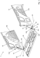
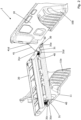
- Fig. 1 shows a left body part 10 and a right body part 11 of an automobile 1 configured as a pick-up automobile. One can see the cavities 10a and 11a for accomodating the tires.
- the automobile 1 further comprises a flap 20 configured as a tailgate, which is pivotally connected to the body parts 10, 11 using a first and a second hinge arrangement 30.
- the hinge arrangements 30 each comprises a tailgate-side hinge part 31 and a body-side hinge part (not illustrated) for allowing rotation about a hinge axis 33 defined by an hinge eye 34.
- the tailgate-side hinge part 31 comprises a proximal first portion 31a including the hinge eye 34, a lateral second portion 31b bent by 90° and substantially arranged flush with the upper surface of tailgate 20, and a third distal portion 31c showing substantially an L-shape, and a fourth portion 31d being bent by 90° from the distal end of the third distal portion 31c being substantially parallel to the tailgate 20.
- Each fourth portion 31d of the tailgate-side hinge parts 31 supports a force assist arrangement 40, to which a rope 41 configured a steel cable with a plastic coating, e.g. made of polyamide, is connected, wherein a distal end 41d of the rope 41 is connected to respectively one of the body part 10, 11 in such a manner that, in the open position of the flap 20 in which the flap 20 is pivoted away from the body 10, 11 by approximately 90 degrees, the rope 41 is arranged substantially in a 45 degree angle with respect to the flap and the body.
- the length of the rope 41 connected to force assist arrangement 40 and body parts 10, 11 defines the opening angle of the flap 20, and the length of rope 41 is accordingly configured to exactly achieve an opening angle of 90°.
- the inclination of the rope 41 can vary within a large range, e.g. between 30 and 60 degrees with respect to one of the flap 20 and the body.
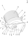
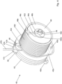
- the force assist arrangement 40 for flap 20 of automobile 1 comprises a rope guide 42 for enrolling the rope 41 and a spring arrangement 43 urging the rope guide 42 towards a closed position of the flap 20.
- the rope guide 42 is connected to a rotatable shaft 44 for common rotation, while the shaft 44 is rotatably connected to a support member 45 comprising a first bracket member 45a and a second bracket member 45b.
- distal end 41d of rope 41 can also be connected to the body-side hinge part (not illustrated), thus allowing to configure a ready-to-build-in assembly consisting of the force assist arrangement 40, the rope 41 and the hinge assembly 30.
- the rope 41 is configured to be substantially unwound from the rope guide 42 when the flap 20 is open, and the rope 41 is substantially wound on the rope guide 42 when the flap 20 is closed.
- the rope guide 42 is substantially disc-shaped and comprises an inner disc portion with a circumference 42b for enroling the rope 41, wherein said inner disc portion is axially surrounded on both extremeties respectively by an outer disc portion 42c.
- the outer disc portion 42c is configured with a V-shaped recess 42v, the bottom of the V-shaped recess 42v having a radial distance to the rotation axis of the rope guide 42 equal to the radius of the circumference 42b.
- the surfaces of the outer disc portion 42c facing away the inner ring portion comprise a reinforcement ring 42r, which shows, on the upper end in the vicinity of the V-shaped recess 42v, a clearance 42e with parallel surfaces facing each other.
- the shaft 44 has a prismatic contour having a square cross section and is received in a fitting square cross section opening 42a of the rope guide 42 for common rotation.
- the shaft 44 accordingly traverses the opening 42a.
- a slot like recess 44a is provided in the shaft 44.
- the bracket members 45a, 45b are made of bent sheet metal steel parts of substantially L-shape cross section having two legs, wherein holes 453 for affixing the bracket members 45a, 45b to the fourth portion 31d of hinge part 31 are provided in a horizontal leg of bracket members 45a, 45b.
- the first bracket member 45a and the second bracket member 45b each have a cylindrical bore 451 in the vertical leg of the respective bracket member, into whicht bore 451 a bushing member 452 made of plastic, in particular polyamide, is introduced.
- the bushing member 452 comprises an inner circular portion 452i fitting into the cylindrical bore 451, an outer circular portion 452o configured as a flange making sure that the bushing member 452 cannot be pushed out of the cylindrical bore 451.
- the outer circular portion 452o is accordingly oriented to face the rope guide 42.
- the central portion of the bushing members 452 is provided with a sqare opening 452c matching the cross section of shaft 44, wherein the bushing members 452 are sufficiently rigid not to be permanently or substantially elastically deformed by a rotation of the shaft 44. Accordingly, responsive to a rotation of the shaft 44, the bushing members 452 rotate within the corresponding cylindrical bore 451, thus achieving a reproducible rotational operation of all items attached to shaft 44.
- a lever member 46 is respectively arranged.
- the lever member 46 is a flat elongated metal sheet part having a square opening 46a at ist lower end and a cylindrical opening 46b at its upper end. It has to be noted that both lever members 46 are identical in shape, such that in particular the axes of cylindrical opening 46b of both levers 46 are coaxially arranged.
- the square opening 46a of the levers 46 allows shaft 44 to traverse them and couples the levers 46 in rotation with shaft 44.
- the thickness of the flat lever member 46 corresponds to the thicknes of reinforcement ring 42r over the exterior surface of outer disc portion 42c, and the width of flat lever member 46 corresponds to the clearance 42e of of reinforcement ring 42r, such that the lever 46 and the axial face of the rope guide 42 mate to become an operational unit.
- a rope terminal 47 having two parallel pins 47a protruding from a flat axial surface 47b comprises a rounded circumference 47c between the surfaces 47b, wherein the thickness of the rope terminal 47 defined by the two axial surfaces 47b corresponds to a width of the inner disc portion, while the pins 47a are configured to rotationally engage the cylindrical opening 46b of the levers 46. More precisely, the levers 46 can either be axially pushed inwardly to engage the rope guide 42 and the pins 47a, or the rope terminal 47 hat its pins 47a engaging the cylindrical opening 46b and the levers 46 are then displaced radially along the clearances 42c.
- the rope terminal 47 can freely rotate within the cylindrical openings 46b by an angle of at least 180 degrees, wherein the distance of the rounded circumference 47c of rope terminal 47 is configured not to get into frictional contact with circumference 42b of the inner disc portion.
- the rope terminal 47 comprises a radial rope attachment 47d pointing upwardly in Fig. 6 , to which a proximal end of the rope 41 can be affixed, either in a releasable manner or preferably in a permanent manner.
- the rope guide 42 with connected rope terminal 47 allows the rope to adapt its orientation depending upon the force of the rope 41, without the rope guide 42 being imparted with forces and moments, as these are transferred to the shaft 44 via the levers 46.
- the rope terminal 47 with rope attachment 47d is substantially tangentially oriented.
- the rounded circumference 47c then prolongates the circumference 42b of the inner disc portion, such that the rope 41 can be wound more that one time around circumference 42b of rope guide 42, e.g. two or three times.
- the length of rope 41 is between 0.9 and 1.8 times the 360° circumference 42b, in particular 1.3 revolutions.
- the two axial surfaces 47b allow the rope terminal 47 to freely rotate between the levers 46. Futher, the two axial surfaces 47b are configured such that the rope terminal 47 can enter within the space delimited by the outer disc portion 42b, even beyond V-shaped recess 42v.
- V-shaped recess 42v is provided for facilitating the introduction of pins 47a into cylindrical opening 46b of the levers 46, and that accordingly another suitable shape, e.g. a U-shape, can be selected.
- a cup-shaped cylinder 48 forming part of spring arrangement 43 is made of plastic or sheet-metal, in the present case produced of a polyamide, and is attached the distal bracket members 45b, by any suitable manner known to a skilled person.
- the cup-shaped cylinder 48 comprises a hollow cylindrical circumference wall 48a, the distal end thereof being delimited by a flat axial wall 48b showing a central opening 48c for allowing the slotted portion 44a of the shaft 44 to protrude therethrough.
- the cup-shaped cylinder 48 is provided, at its proximal end, with L-shaped protrusions 48d configured to engage corresponding slots 454 in bracket members 45b, where the legs of the L-shaped protrusions 48d first penetrate the slots 454 and then, subsequent to a (partial) rotation of cup-shaped cylinder 48, are affixed to the bracket members 45b. It is possible to provide for that the two parts 45b, 48 do not disengage again during operation.
- Central opening 48c has a circular shape and acocomodates another bushing member 452 similar to those described above, having a square opening 452c for receiving the square shaft 44 in the region of its slotted recess 44a defining a drive area.
- Spring arrangement 43 in the present embodiment comprises a first spring member 430 configured as a rotational spring having several, e.g. 10 to 15, convolutions, having a first leg 431 bent in an axial direction to engage the second bracket 45b and a second leg 432 bent in a radially inward direction to engage the slotted portion 44a of shaft 44.
- the first spring member 430 In the closed position of flap 20, the first spring member 430 is substantially relaxed, even if perhaps not completely relaxed.
- the first spring member 430 In the open position of flap 20, the first spring member 430 is substantially loaded by the rotational relative movement of shaft 44 with respect to the brackets 45a, 45b.
- the convolutions of the first spring member 430 are arranged to be supported by externally adjoining the circumference wall 48a of the cup-shaped cylinder 48, thus avoiding any other deformation to be imparted on first spring member 430 than the loading of first spring member 430 in a rotational sense.
- the second spring member 430' In the closed position of flap 20, the second spring member 430' is also substantially or at least mainly relaxed.
- the second spring member 430' In the open position of flap 20, the second spring member 430' is substantially loaded by the rotational relative movement of shaft 44 with respect to the brackets 45a, 45b.
- the convolutions of the first spring member 430 are arranged to be supported by internally adjoining the circumference wall 48a of the cup-shaped cylinder 48, thus avoiding any other deformation to be imparted on second spring member 430' than the loading of second spring member 430' in a rotational sense. It results a very compact design of the spring arrangement 43 and consequently of the total dimensions of force assist arrangement 40, allowing it to be easily accomodated within flap 10.
- the slotted recess 44a is accordingly the portion of shaft 44 imparting rotational moments from and to the spring members 430, 430' and thus defining a drive area of the shaft.
- both spring member 430, 430' are working into the same way - accordingly, certain configurations might be sufficiently imparted upon by one single spring member 430.
- a motor can be connected drive the assembly 40, e.g. having a drive axle supporting a worm gear meshing e.g. with extermal teeth radially provided on outer disc portion 42c in order to open or close the flap 20 by unreeling or reeling the rope 41, simultaneously loading the spring arrangement 43 or being assisted by the spring arrangement 43.
- the invention now operates as follows: Starting from a closed position of flap 20, where flap 20 is arranged in a substantially vertical position adjoining the body 10, 11, the flap 20 can be pivoted about pivot axis 33 to a substantially horizontal open position providing access to a load floor of the automobile 1. During the opening movement, a force either by manual operation or by motor operation or by the weight of the flap 20 (or combinations thereof) is imparted upon the springs 430, 430', loading them in the closing direction.
- the rope 41 ensures by its length configuration that even when being pressed downwards, the flap 20 remains in its horizontal open position, such that no additional abuttment is needed. This is mainly achieved by the fact that the forces acting on the rope 41, via the rope terminal 47 and the levers 46, is directly held on the shaft 44.
- the springs 430, 430' act against the load of the flap 20 and support the closing pivotal movement. During this pivotal movement, the springs 430, 430' further urge, via shaft 44 being attached to the springs 430, 430', to commonly rotate rope guide 42 and levers 46 and subsequently to reel rope 41 on rope guide 42. The rope terminal 47 then rotates within levers 46 to align with circumference 42b of inner ring portion 42a such that the rope 41 can be arranged in a defined way within rope guide 42, avoiding any jamming.
- the spring arrangement 43 could also be replaced by a motor driving the rope guide 42, although a combination of a motor and the spring arrangement 43 is preferred. Accordingly, the present disclosure is intended to encompass a solution where a motor is provided instead of the spring arrangement 43, where the motor moves the flap 20 upwardly and downwardly by changing its direction of rotation. Such embodiment could also be realized by having a drive shaft of the motor driving shaft 44, preferably with an intermeshing gear arrangement.
- a flap with force assist arrangement 40 having a motor-driven embodiment on one side of the flap and a force assist arrangement 40 having a spring arrangement 43 on the other side of the flap.
- one spring arrangement 43 is provided being attached to the second bracket member 45b. It has to be understood that a second spring arrangement could be attached to another bracket member, e.g. an additional bracket member or preferably the first bracket member 45a, e.g. facing away the second bracket member 45b. In this configuration, the length of the shaft 44 would be somewhat longer, but the forces and moments acting thereron and the amount of spring members would be increased.
Landscapes
- Engineering & Computer Science (AREA)
- Mechanical Engineering (AREA)
- Vehicle Step Arrangements And Article Storage (AREA)
- Lock And Its Accessories (AREA)
Abstract
Description
- The invention relates to a force assist arrangement for a flap of an automobile, which allows to assist the user in particular in closing a flap of the automobile such as a tail gate.
-
DE 199 16 092 A1 describes a force assist arrangement for a flap of an automobile, comprising a rope connectable to one of the flap and a body of the automobile and a rope guide configured as pulley for enrolling the rope. A spring arrangement urging the rope guide towards a closed position of the flap is configured as volute spring and is arranged at a level of the top of the flap, wherein the rope is substantially unwound from the rope guide when the flap is open, and wherein the rope is substantially wound on the rope guide when the flap is closed. The rope comprises an abutment portion configured to abut against a receiving portion provided on the body of the automobile, wherein the abutment portion and the receiving portion commonly support the flap in the openend position, where enrolling the abutment portion on the rope guide entails play of the rope. The volute spring generates a torque sufficient to enroll the rope, but the assistance for the user is neglectable. The rope needs to be enrolled several times around the rope guide which has a large diameter, such that the resulting package can only hardly be accomodated within one of flap or body. In the open position of the flap, the rope is very distant from the articulation of flap, such that merchandises nearby cannot be put on the flap from the side. - It is the object of the invention to provide a small-sized force assist arrangement for a flap and an automobile that provides a force supporting the user in closing the flap.
- This object is achieved according to the invention by a force assist arrangement and an automobile having the features defined in an independent claim.
- According to an aspect of the invention, a force assist arrangement for a flap of an automobile is provided, the force assist arrangement comprising a rope connectable to one of the flap and a body of the automobile; a rope guide for enrolling the rope; and a spring arrangement urging the rope guide towards a closed position of the flap; wherein the rope is substantially unwound from the rope guide when the flap is open, and wherein the rope is substantially wound on the rope guide when the flap is closed. The force assist arrangement further distinguishes in that the rope guide is connected to a rotatable shaft for common rotation, that the shaft is rotatably connected to a support member, that the spring arrangement comprises a first end supported against a support area of the support member, and that the spring arrangement comprises a second end supported against a drive area of the shaft. The force assist arrangement is extremely compact and at the same time very firm, and allows to load the spring arrangement while pivoting down the flap, which load assists a user in pivoting up the flap again.
- According to a preferred developpment, the spring arrangement comprises a first spring member configured as a helical spring. Helical springs are easy to produce, not expensive and have spring characteristics that are quite reproducible. The helical spring is particularly suitable for imparting a rotational torque.
- A further improvent is provided in that the first spring member comprises several convolutions around the exterior lateral area of a cup-shaped cylinder. The cup-shaped cylinder prevents the first spring member from tilting or deforming when being loaded, such that the complete load of the rotative deformation of the first spring member can be provided to assist a user in closing the flap.
- In a still improved embodiment, the spring arrangement comprises a second spring member configured as a helical spring. The second spring member can be arranged coaxially with the first spring member, but preferably the two spring members independently act on the shaft. For this purpose, the two spring members can be arranged nested the one into the other, in particular in a concentric manner, such that the outcome is a high torque achieved in a compact space. Both spring members are loaded in the same direction of the flap movement and accordingly, their respective torques can be added.
- Preferably, the second spring member comprises several convolutions within the interior lateral area of a cup-shaped cylinder. The cup-shaped cylinder with its exterior cylinder wall prevents the second spring member from jamming or deforming differently than intended to provide a torque for closing the flap.
- Further, the cup-shaped cylinder is preferably made from a plastics like polyamide or the like, thus avoiding noise, e.g. when the spring members deform, by avoiding a direct contact.
- In a convenient improvement, the shaft has a prismatic contur and is received in a fitting opening of the rope guide for common rotation. For example, the shaft can have a square cross section, and the opening of the rope guide has a fitting square cross section, or any prismatic cross section allowing the shaft to be coupled to the rope guide in rotation. It is possible, but not preferred, that the rope guide is pressfitted onto the shaft, as the right fitting enables quick assembly.
- In a further refinement, the shaft penetrated into fitting openings of bushings that can rotate in an eye of a first and a second bracket for attachment to the one of the flap and the body. Preferably, the central openings of the bushings have a square or other prismativ cross section configured to receive the shaft substantially without play, such that a rotational movement of the shaft is imparted to the bushings. Same applies for a square opening of the rope guide or of a lever.
- In a preferred embodiment, the the cup-shaped cylinder is attached to one of the brackets such that the cup-shaped cylinder form a part of the support that is immovable with respect to e.g. the flap. The cup-shaped cylinder is preferably provided with an eye coaxially to the eyes of the brackets, such that the shaft can also be rotate in said eye using a bushing similar to the bushings mentioned above. Instead of a cup-shaped cylinder, an open cylinder could be provided if the bearing functionality is not needed.
- According to particular preferred improvement, the brackets are connected on a hinge member that allows pivoting of the flap with respect to the body. In this preferred configutation, the hinge allowing pivotal movement of the flap and the force assist arrangement limiting the pivotal angle can be provided in a common unit, thus making assemby easy and avoiding confusion of parts during assembly.
- In an expedient refinement, a first lever and a second lever are arranged adjacent an axial face of the rope guide, wherein the first lever and the second lever each comprise a fitting opening for the shaft, and wherein the first lever and the second lever are commonly rotating with the rope guide. This configuration ensures that the levers are always oriented in the same direction as the shaft and as the rope guide, excluding any rotational play between these parts.
- According to a preferred improvement, the rope guide comprises a circumferential slot for accomodating the rope when the rope in enrolled while the flap is closed.
- In a further development, the first lever and the second lever both comprise a coaxial opening for pivotably receiving a pin portion of a rope terminal of the rope. This ensures that the forces and torques transmitted by the rope are transferred directly from the rope terminal through the levers to the shaft, allowing in particular to use a less rigid and expensive material for the rope guide such as plastic without risking to damage its central bore receiving the shaft. Further, the rope does not need to be attached directly to the rope guide.
- In the preferred configuration of the pin portion being rotatably attached to the levers, the pin portion can take an orientation depending upon the angle the rope takes with respect to the body.
- In a still improved embodiment, the rope terminal comprises a protrusion to which the rope is fixed that is capable to pivot into the slot in such a way that the rope can enroll more than 360 degrees over the lateral surface of the rope terminal.
- Expediently, the shaft comprises a slotted end allowing the introduction of an end portion of the spring arrangement. As torques and forces of the spring arrangement in general and of the spring members in particular are imparted to the slotted area of the shaft by introducing the respective legs of the spring members into said slot, the slotted area of the shaft can also be designated as drive area.
- Preferably, the flap can be pivoted downward under the load of gravity, that the spring arrangement is tensioned by the downward pivoting, and that the spring arrangement assists in pivoting upward the flap.
- In a still further improvement, the rotational opening and closing movement of the flap can additionally be supported by a drive. The drive then comprises a motor driving an output shaft, which in turn is configured as a worm member meshing with teeth of e.g. the rope guide. In this configuration, the rope guide is made of steel or another material resisant to wear.
- Preferably, the shaft is secured against axial displacement, e.g. using a security pin or by deforming the shaft to avoid axial displacement. In a more refined configuration, the slotted recess of the shaft traverses a bushing member provided in the central opening in the front side of the cup shaped cylinder, and adjacent both axial sides of said bushing member, a leg of the first and the second spring member tranverse the recess, thus fixing the shaft axially. In further refinement, the shaft then does not comprise a single recess, but rather two holes or recess portions for accomodating the respective legs of the two spring members.
- The rope is preferably a metal cable that is coated with a plastic coating such as a polyamide, thus avoiding corrosion and other frictional noises.
- According to an aspect of the invention, an automobile is provided, comprising a first and a second force assist arrangement as described above as being according to the invention, the first and second force assist arrangements being arranged adjacent to a first and a second hinge coupling the flap to the body.
- In an expedient improvement, the first and second force assist arrangements are arranged within the flap. While space is nearby not available within the body, or arranging a force assist arrangement in the body restricts the available volume for transporting goods, the flap much more convenient in receiving the force assist arrangements, if these are as compact as described above.
- In a still more expedient improvement, a distal end of the rope is connected to the body in such a manner that, in the open position of the flap in which the flap is pivoted away from the body by approximately 90 degrees, the rope is arranged substantially in an angle range between 30 degrees and 60 degrees, preferably in a 45 degree angle with respect to the flap and the body. Accordingly, the rope can take a 45 degree +/- 15 degree angle with respect to one of the flap and the body, and the complementary angle to achieve 90 degrees with respect to the other of the flap and the body.
- When the force assist arrangements are arranged close to or together with the hinge arrangements, the length of the ropes is minimized, and the barrier constituted by the rope small and perturbing any loading operation only to a very low extend.
- Further improvements, advantages and features will become appearant from the dependent claims as well as from the following description of a preferred embodiment of the invention.
- The invention is subsequently described with reference to the appended drawings with regard to a preferred embodiment of the invention.
- Fig. 1
- shows a perspective view on parts of an automobile having a liftgate connected to to the body via a cable.
- Fig. 2
- shows a perspective view on the parts of
Fig. 1 from below. - Fig. 3
- shows a perspective view on force assist arrangement and the cable of
Fig. 1 and2 . - Fig. 4
- shows the force assist arrangement of
Fig. 3 from another perspective. - Fig. 5
- shows a sectional view along a shaft axis of the force assist arrangement of
Fig. 3 and4 . - Fig. 6
- shows an exploded view of the force assist arrangement of
Fig. 3 to 5 . -
Fig. 1 shows aleft body part 10 and aright body part 11 of anautomobile 1 configured as a pick-up automobile. One can see thecavities automobile 1 further comprises aflap 20 configured as a tailgate, which is pivotally connected to thebody parts second hinge arrangement 30. Thehinge arrangements 30 each comprises a tailgate-side hinge part 31 and a body-side hinge part (not illustrated) for allowing rotation about ahinge axis 33 defined by anhinge eye 34. The tailgate-side hinge part 31 comprises a proximalfirst portion 31a including thehinge eye 34, a lateralsecond portion 31b bent by 90° and substantially arranged flush with the upper surface oftailgate 20, and a thirddistal portion 31c showing substantially an L-shape, and afourth portion 31d being bent by 90° from the distal end of the thirddistal portion 31c being substantially parallel to thetailgate 20. - Each
fourth portion 31d of the tailgate-side hinge parts 31 supports a force assistarrangement 40, to which arope 41 configured a steel cable with a plastic coating, e.g. made of polyamide, is connected, wherein adistal end 41d of therope 41 is connected to respectively one of thebody part flap 20 in which theflap 20 is pivoted away from thebody rope 41 is arranged substantially in a 45 degree angle with respect to the flap and the body. The length of therope 41 connected to forceassist arrangement 40 andbody parts flap 20, and the length ofrope 41 is accordingly configured to exactly achieve an opening angle of 90°. Depending upon the selected location of the connection of thedistal end 41d of therope 41 and/or of the position, configuration, size of the force assistarrangement 40, the inclination of therope 41 can vary within a large range, e.g. between 30 and 60 degrees with respect to one of theflap 20 and the body. - As one particularly can see in
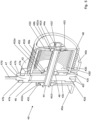
Fig. 3 to 6 , the force assistarrangement 40 forflap 20 ofautomobile 1 comprises arope guide 42 for enrolling therope 41 and aspring arrangement 43 urging therope guide 42 towards a closed position of theflap 20. Therope guide 42 is connected to arotatable shaft 44 for common rotation, while theshaft 44 is rotatably connected to asupport member 45 comprising afirst bracket member 45a and asecond bracket member 45b. - One can note that the
distal end 41d ofrope 41 can also be connected to the body-side hinge part (not illustrated), thus allowing to configure a ready-to-build-in assembly consisting of the force assistarrangement 40, therope 41 and thehinge assembly 30. Therope 41 is configured to be substantially unwound from therope guide 42 when theflap 20 is open, and therope 41 is substantially wound on therope guide 42 when theflap 20 is closed. - The
rope guide 42 is substantially disc-shaped and comprises an inner disc portion with acircumference 42b for enroling therope 41, wherein said inner disc portion is axially surrounded on both extremeties respectively by anouter disc portion 42c. Theouter disc portion 42c is configured with a V-shapedrecess 42v, the bottom of the V-shapedrecess 42v having a radial distance to the rotation axis of therope guide 42 equal to the radius of thecircumference 42b. The surfaces of theouter disc portion 42c facing away the inner ring portion comprise areinforcement ring 42r, which shows, on the upper end in the vicinity of the V-shapedrecess 42v, aclearance 42e with parallel surfaces facing each other. - The
shaft 44 has a prismatic contur having a square cross section and is received in a fitting squarecross section opening 42a of therope guide 42 for common rotation. Theshaft 44 accordingly traverses theopening 42a. On a distal portion of theshaft 44, a slot likerecess 44a is provided in theshaft 44. - The
bracket members holes 453 for affixing thebracket members fourth portion 31d ofhinge part 31 are provided in a horizontal leg ofbracket members first bracket member 45a and thesecond bracket member 45b each have acylindrical bore 451 in the vertical leg of the respective bracket member, into whicht bore 451 abushing member 452 made of plastic, in particular polyamide, is introduced. Thebushing member 452 comprises an innercircular portion 452i fitting into thecylindrical bore 451, an outer circular portion 452o configured as a flange making sure that thebushing member 452 cannot be pushed out of thecylindrical bore 451. The outer circular portion 452o is accordingly oriented to face therope guide 42. The central portion of thebushing members 452 is provided with asqare opening 452c matching the cross section ofshaft 44, wherein thebushing members 452 are sufficiently rigid not to be permanently or substantially elastically deformed by a rotation of theshaft 44. Accordingly, responsive to a rotation of theshaft 44, thebushing members 452 rotate within the correspondingcylindrical bore 451, thus achieving a reproducible rotational operation of all items attached toshaft 44. - Between the
first bracket member 45a and thesecond bracket member 45b (and their respective bushings members 452) on the one hand and therope guide 42 on the other hand, alever member 46 is respectively arranged. Thelever member 46 is a flat elongated metal sheet part having asquare opening 46a at ist lower end and acylindrical opening 46b at its upper end. It has to be noted that bothlever members 46 are identical in shape, such that in particular the axes ofcylindrical opening 46b of bothlevers 46 are coaxially arranged. Thesquare opening 46a of thelevers 46 allowsshaft 44 to traverse them and couples thelevers 46 in rotation withshaft 44. The thickness of theflat lever member 46 corresponds to the thicknes ofreinforcement ring 42r over the exterior surface ofouter disc portion 42c, and the width offlat lever member 46 corresponds to theclearance 42e of ofreinforcement ring 42r, such that thelever 46 and the axial face of therope guide 42 mate to become an operational unit. - A
rope terminal 47 having twoparallel pins 47a protruding from a flataxial surface 47b comprises arounded circumference 47c between thesurfaces 47b, wherein the thickness of therope terminal 47 defined by the twoaxial surfaces 47b corresponds to a width of the inner disc portion, while thepins 47a are configured to rotationally engage thecylindrical opening 46b of thelevers 46. More precisely, thelevers 46 can either be axially pushed inwardly to engage therope guide 42 and thepins 47a, or therope terminal 47 hat itspins 47a engaging thecylindrical opening 46b and thelevers 46 are then displaced radially along theclearances 42c. Therope terminal 47 can freely rotate within thecylindrical openings 46b by an angle of at least 180 degrees, wherein the distance of the roundedcircumference 47c ofrope terminal 47 is configured not to get into frictional contact withcircumference 42b of the inner disc portion. Therope terminal 47 comprises aradial rope attachment 47d pointing upwardly inFig. 6 , to which a proximal end of therope 41 can be affixed, either in a releasable manner or preferably in a permanent manner. As a result, therope guide 42 withconnected rope terminal 47 allows the rope to adapt its orientation depending upon the force of therope 41, without therope guide 42 being imparted with forces and moments, as these are transferred to theshaft 44 via thelevers 46. When the rope is enrolled, therope terminal 47 withrope attachment 47d is substantially tangentially oriented. Therounded circumference 47c then prolongates thecircumference 42b of the inner disc portion, such that therope 41 can be wound more that one time aroundcircumference 42b ofrope guide 42, e.g. two or three times. - In the present embodiment, the the length of
rope 41 is between 0.9 and 1.8 times the 360°circumference 42b, in particular 1.3 revolutions. The twoaxial surfaces 47b allow therope terminal 47 to freely rotate between thelevers 46. Futher, the twoaxial surfaces 47b are configured such that therope terminal 47 can enter within the space delimited by theouter disc portion 42b, even beyond V-shapedrecess 42v. One will understand that V-shapedrecess 42v is provided for facilitating the introduction ofpins 47a intocylindrical opening 46b of thelevers 46, and that accordingly another suitable shape, e.g. a U-shape, can be selected. - A cup-shaped
cylinder 48 forming part ofspring arrangement 43 is made of plastic or sheet-metal, in the present case produced of a polyamide, and is attached thedistal bracket members 45b, by any suitable manner known to a skilled person. The cup-shapedcylinder 48 comprises a hollowcylindrical circumference wall 48a, the distal end thereof being delimited by a flataxial wall 48b showing acentral opening 48c for allowing the slottedportion 44a of theshaft 44 to protrude therethrough. In the present embodiment, the cup-shapedcylinder 48 is provided, at its proximal end, with L-shapedprotrusions 48d configured to engage correspondingslots 454 inbracket members 45b, where the legs of the L-shapedprotrusions 48d first penetrate theslots 454 and then, subsequent to a (partial) rotation of cup-shapedcylinder 48, are affixed to thebracket members 45b. It is possible to provide for that the twoparts -
Central opening 48c has a circular shape and acocomodates anotherbushing member 452 similar to those described above, having asquare opening 452c for receiving thesquare shaft 44 in the region of its slottedrecess 44a defining a drive area. -
Spring arrangement 43 in the present embodiment comprises afirst spring member 430 configured as a rotational spring having several, e.g. 10 to 15, convolutions, having afirst leg 431 bent in an axial direction to engage thesecond bracket 45b and asecond leg 432 bent in a radially inward direction to engage the slottedportion 44a ofshaft 44. In the closed position offlap 20, thefirst spring member 430 is substantially relaxed, even if perhaps not completely relaxed. In the open position offlap 20, thefirst spring member 430 is substantially loaded by the rotational relative movement ofshaft 44 with respect to thebrackets first spring member 430 are arranged to be supported by externally adjoining thecircumference wall 48a of the cup-shapedcylinder 48, thus avoiding any other deformation to be imparted onfirst spring member 430 than the loading offirst spring member 430 in a rotational sense. - A second spring member 430' having a somewhat smaller diameter that the
first spring member 430 is also configured as a rotational spring having several, e.g. 12 to 18, convolutions, having a first leg 431' bent in an axial direction to engage thesecond bracket 45b and a second leg 432' bent in a radially inward direction to engage the slottedportion 44a ofshaft 44. In the closed position offlap 20, the second spring member 430' is also substantially or at least mainly relaxed. In the open position offlap 20, the second spring member 430' is substantially loaded by the rotational relative movement ofshaft 44 with respect to thebrackets first spring member 430 are arranged to be supported by internally adjoining thecircumference wall 48a of the cup-shapedcylinder 48, thus avoiding any other deformation to be imparted on second spring member 430' than the loading of second spring member 430' in a rotational sense. It results a very compact design of thespring arrangement 43 and consequently of the total dimensions of force assistarrangement 40, allowing it to be easily accomodated withinflap 10. The slottedrecess 44a is accordingly the portion ofshaft 44 imparting rotational moments from and to thespring members 430, 430' and thus defining a drive area of the shaft. - As one can easily conceive, both
spring member 430, 430' are working into the same way - accordingly, certain configurations might be sufficiently imparted upon by onesingle spring member 430. - As one can further easily conceive, a motor can be connected drive the
assembly 40, e.g. having a drive axle supporting a worm gear meshing e.g. with extermal teeth radially provided onouter disc portion 42c in order to open or close theflap 20 by unreeling or reeling therope 41, simultaneously loading thespring arrangement 43 or being assisted by thespring arrangement 43. - The invention now operates as follows:
Starting from a closed position offlap 20, whereflap 20 is arranged in a substantially vertical position adjoining thebody flap 20 can be pivoted aboutpivot axis 33 to a substantially horizontal open position providing access to a load floor of theautomobile 1. During the opening movement, a force either by manual operation or by motor operation or by the weight of the flap 20 (or combinations thereof) is imparted upon thesprings 430, 430', loading them in the closing direction. Therope 41 ensures by its length configuration that even when being pressed downwards, theflap 20 remains in its horizontal open position, such that no additional abuttment is needed. This is mainly achieved by the fact that the forces acting on therope 41, via therope terminal 47 and thelevers 46, is directly held on theshaft 44. - When the
flap 20 is lifted up again, thesprings 430, 430' act against the load of theflap 20 and support the closing pivotal movement. During this pivotal movement, thesprings 430, 430' further urge, viashaft 44 being attached to thesprings 430, 430', to commonly rotaterope guide 42 and levers 46 and subsequently to reelrope 41 onrope guide 42. Therope terminal 47 then rotates withinlevers 46 to align withcircumference 42b ofinner ring portion 42a such that therope 41 can be arranged in a defined way withinrope guide 42, avoiding any jamming. - As one will easily understand, the
spring arrangement 43 could also be replaced by a motor driving therope guide 42, although a combination of a motor and thespring arrangement 43 is preferred. Accordingly, the present disclosure is intended to encompass a solution where a motor is provided instead of thespring arrangement 43, where the motor moves theflap 20 upwardly and downwardly by changing its direction of rotation. Such embodiment could also be realized by having a drive shaft of themotor driving shaft 44, preferably with an intermeshing gear arrangement. Of course, it is possible to provide a flap with force assistarrangement 40 having a motor-driven embodiment on one side of the flap and a force assistarrangement 40 having aspring arrangement 43 on the other side of the flap. - The invention has been described above with regard to an embodiment where one
spring arrangement 43 is provided being attached to thesecond bracket member 45b. It has to be understood that a second spring arrangement could be attached to another bracket member, e.g. an additional bracket member or preferably thefirst bracket member 45a, e.g. facing away thesecond bracket member 45b. In this configuration, the length of theshaft 44 would be somewhat longer, but the forces and moments acting thereron and the amount of spring members would be increased. - The invention has been described above with regard to an embodiment where the
rope terminal 47 is attached to twolevers 46. It has to be understood that thepins 47a could also be rotatably connected to corresponding cylindrical openings in the rope guide, e.g. within the reinforcement ring of theouter disc portions 42c, where theouter disc portion 42c then can be axially assembled to form the rope guide.
Claims (15)
- A force assist arrangement for a flap (20) of an automobile (1), comprisinga rope (41) connectable to one of the flap (20) and a body (10, 11) of the automobile (1);a rope guide (42) for enrolling the rope (41); anda spring arrangement (43) urging the rope guide (42) towards a closed position of the flap (20);wherein the rope (41) is substantially unwound from the rope guide (42) when the flap (20) is open,wherein the rope (41) is substantially wound on the rope guide (42) when the flap (20) is closed,characterized inthat the rope guide (42) is connected to a rotatable shaft (44) for common rotation,that the shaft (44) is rotatably connected to a support member (45),that the spring arrangement (43) comprises a first end (431; 431') supported against a support area (45b) of the support member (45), and that the spring arrangement (43) comprises a second end (432; 432') supported against a drive area (441) of the shaft (44).
- The force assist arrangement arrangement according to claim 1, characterized in that the spring arrangement (43) comprises a first spring member (430) configured as a helical spring.
- The force assist arrangement arrangement according to claim 2, characterized in that the first spring member (430) comprises several convolutions around an exterior lateral area (48a) of a cup-shaped cylinder (48).
- The force assist arrangement arrangement according to claim 2 or 3, characterized in that the spring arrangement (43) comprises a second spring member (430') configured as a helical spring.
- The force assist arrangement arrangement according to claim 4, characterized in that the second spring member (430') comprises several convolutions within the interior lateral area (48a) of a cup-shaped cylinder (48).
- The force assist arrangement arrangement according to any of the preceding claims, characterized in that the shaft (44) has a prismatic contur and is received in a fitting opening (42a) of the rope guide (42) for common rotation, and that the shaft (44) penetrated into fitting openings (452c) of bushings (452) that can rotate in an eye of a first and a second bracket (45a, 45b) for attachment to the one of the flap (20) and the body (10, 11).
- The force assist arrangement arrangement according to claim 6 and claim 3 or 5, characterized in that the cup-shaped cylinder (48) is attached to one of the brackets (45b).
- The force assist arrangement arrangement according to claim 6 or 7, characterized in that the brackets (45a; 45b) are connected on a hinge member (30( that allows pivoting of the flap (20) with respect to the body (10, 11).
- The force assist arrangement arrangement according to any of the preceding claims, characterized in that a first lever (46) and a second lever (46) are arranged adjacent an axial face of the rope guide (42), that the first lever (46) and the second lever (46) each comprise a fitting opening (46a) for the shaft (44), wherein the first lever (46) and the second lever (46) are commonly rotating with the rope guide (42).
- The force assist arrangement arrangement according to claim 9, characterized in that the first lever (46) and the second lever (46) both comprise a coaxial opening (46b) for pivotably receiving an pin portion (47a) of a rope terminal (47) of the rope (41).
- The force assist arrangement arrangement according to claim 10, characterized in that the rope guide (42) comprises a circumferential slot (42b) for accomodating the rope (41), and that the rope terminal (47) comprises a protrusion (47d) to which the rope (41) is fixed, and that the rope terminal (47) is capable to pivot aroud the pin portions (46a) into the slot (42b) is such a way that the rope (41) can enroll more than 360 degrees over the lateral surface (47c) of the rope terminal (47).
- The force assist arrangement according to any of the preceding claims, characterized in that the shaft (44) comprises a slotted end (44a) allowing the introduction of an end portion (432; 432') of the spring arrangement (43).
- The force assist arrangement according to any of the preceding claims, characterized in that the flap (20) can be pivoted downward under the load of gravity, that the spring arrangement (43) is tensioned by the downward pivoting, and that the spring arrangement (43) assists in pivoting upward the flap (20).
- An automobile having a body (10, 11) and a flap (20), characterized by a first and a second force assist arrangement (40) according to any of claims 1 to 13, one of the first and second force assist arrangements (40) being arranged adjacent to a first and a second hinge (30) coupling the flap (20) to the body (10, 11).
- The automobile according to claim 14, characterized in that the first and second force assist arrangements (40) are arranged within the flap (20), and that a distal end (41d) of the rope (41) is connected to the body (10, 11) in such a manner that, in the open position of the flap (20) in which the flap is pivoted away from the body (10, 11) by approximately 90 degrees, the rope (41) is arranged substantially in an angle range between 30 degrees and 60 degrees, preferably in a 45 degree angle with respect to the flap (20) and the body (10, 11).
Priority Applications (2)
| Application Number | Priority Date | Filing Date | Title |
|---|---|---|---|
| EP23213809.9A EP4563779B1 (en) | 2023-12-01 | 2023-12-01 | Force assist arrangement and automobile equipped therewith |
| PCT/EP2024/084135 WO2025114551A1 (en) | 2023-12-01 | 2024-11-29 | Force assist arrangement for a flap of an automobile |
Applications Claiming Priority (1)
| Application Number | Priority Date | Filing Date | Title |
|---|---|---|---|
| EP23213809.9A EP4563779B1 (en) | 2023-12-01 | 2023-12-01 | Force assist arrangement and automobile equipped therewith |
Publications (2)
| Publication Number | Publication Date |
|---|---|
| EP4563779A1 true EP4563779A1 (en) | 2025-06-04 |
| EP4563779B1 EP4563779B1 (en) | 2025-10-08 |
Family
ID=89073325
Family Applications (1)
| Application Number | Title | Priority Date | Filing Date |
|---|---|---|---|
| EP23213809.9A Active EP4563779B1 (en) | 2023-12-01 | 2023-12-01 | Force assist arrangement and automobile equipped therewith |
Country Status (1)
| Country | Link |
|---|---|
| EP (1) | EP4563779B1 (en) |
Citations (4)
| Publication number | Priority date | Publication date | Assignee | Title |
|---|---|---|---|---|
| JPS6443181U (en) * | 1987-09-08 | 1989-03-15 | ||
| DE19916092A1 (en) | 1999-04-09 | 2000-10-12 | Bayerische Motoren Werke Ag | Support for braking vehicle tailgate as it is lowered, has let=out mechanism keeping it under tension when tailgate is closed |
| EP1331341B1 (en) * | 2002-01-29 | 2006-06-07 | Barnes Group, Inc. | Tailgate stabilizer |
| US20180195332A1 (en) * | 2017-01-10 | 2018-07-12 | GM Global Technology Operations LLC | System with pulleys and steel cable for pick up truck end gate position adjustment |
-
2023
- 2023-12-01 EP EP23213809.9A patent/EP4563779B1/en active Active
Patent Citations (4)
| Publication number | Priority date | Publication date | Assignee | Title |
|---|---|---|---|---|
| JPS6443181U (en) * | 1987-09-08 | 1989-03-15 | ||
| DE19916092A1 (en) | 1999-04-09 | 2000-10-12 | Bayerische Motoren Werke Ag | Support for braking vehicle tailgate as it is lowered, has let=out mechanism keeping it under tension when tailgate is closed |
| EP1331341B1 (en) * | 2002-01-29 | 2006-06-07 | Barnes Group, Inc. | Tailgate stabilizer |
| US20180195332A1 (en) * | 2017-01-10 | 2018-07-12 | GM Global Technology Operations LLC | System with pulleys and steel cable for pick up truck end gate position adjustment |
Also Published As
| Publication number | Publication date |
|---|---|
| EP4563779B1 (en) | 2025-10-08 |
Similar Documents
| Publication | Publication Date | Title |
|---|---|---|
| JP4842149B2 (en) | Single pivot hinge with integrated coil spring assist | |
| US6125908A (en) | Rolling cover for use in covering items stored in a vehicle storage area | |
| US6439730B1 (en) | Extendable mirror with improved detent | |
| US8596153B2 (en) | Drive device | |
| CA2125624C (en) | Quarter window opening/closing apparatus | |
| EP1148196B1 (en) | Vehicle lid hinge | |
| EP0919854A1 (en) | Roll screen | |
| KR102288685B1 (en) | Hinge Apparatus For Arm Rest | |
| EP4563779B1 (en) | Force assist arrangement and automobile equipped therewith | |
| US7028573B2 (en) | Opening and closing device | |
| CN111201359B (en) | Hinge with tensionable spring element | |
| US7290890B2 (en) | Retracting mechanism of vehicular outer mirror device | |
| US11125001B2 (en) | Hinge comprising a biasable flat spiral spring | |
| JPWO2013147164A1 (en) | Door closer | |
| CA2523361C (en) | Tailgate counterbalancing hinge with bend in torque rod | |
| US20230096767A1 (en) | Toilet device | |
| WO2025114551A1 (en) | Force assist arrangement for a flap of an automobile | |
| KR102566746B1 (en) | Open and close apparatus for a tailgate of vehicle | |
| JP3264606B2 (en) | Opening / closing device for opening / closing lid | |
| WO2013154021A1 (en) | Hinge device | |
| KR102557711B1 (en) | Hinge apparatus for vehicle frunk | |
| CN208101837U (en) | Streaming Media rearview mirror | |
| JP2008063762A (en) | Opening and closing body drive device | |
| KR102861638B1 (en) | Open and close apparatus for a tailgate of vehicle | |
| KR20230172214A (en) | Automatic opening and closing device for preventing movement of vehicle door |
Legal Events
| Date | Code | Title | Description |
|---|---|---|---|
| STAA | Information on the status of an ep patent application or granted ep patent |
Free format text: STATUS: EXAMINATION IS IN PROGRESS |
|
| PUAI | Public reference made under article 153(3) epc to a published international application that has entered the european phase |
Free format text: ORIGINAL CODE: 0009012 |
|
| 17P | Request for examination filed |
Effective date: 20240930 |
|
| AK | Designated contracting states |
Kind code of ref document: A1 Designated state(s): AL AT BE BG CH CY CZ DE DK EE ES FI FR GB GR HR HU IE IS IT LI LT LU LV MC ME MK MT NL NO PL PT RO RS SE SI SK SM TR |
|
| GRAP | Despatch of communication of intention to grant a patent |
Free format text: ORIGINAL CODE: EPIDOSNIGR1 |
|
| STAA | Information on the status of an ep patent application or granted ep patent |
Free format text: STATUS: GRANT OF PATENT IS INTENDED |
|
| GRAS | Grant fee paid |
Free format text: ORIGINAL CODE: EPIDOSNIGR3 |
|
| GRAA | (expected) grant |
Free format text: ORIGINAL CODE: 0009210 |
|
| STAA | Information on the status of an ep patent application or granted ep patent |
Free format text: STATUS: THE PATENT HAS BEEN GRANTED |
|
| INTG | Intention to grant announced |
Effective date: 20250811 |
|
| AK | Designated contracting states |
Kind code of ref document: B1 Designated state(s): AL AT BE BG CH CY CZ DE DK EE ES FI FR GB GR HR HU IE IS IT LI LT LU LV MC ME MK MT NL NO PL PT RO RS SE SI SK SM TR |
|
| P01 | Opt-out of the competence of the unified patent court (upc) registered |
Free format text: CASE NUMBER: UPC_APP_5689_4563779/2025 Effective date: 20250903 |
|
| REG | Reference to a national code |
Ref country code: GB Ref legal event code: FG4D Ref country code: CH Ref legal event code: F10 Free format text: ST27 STATUS EVENT CODE: U-0-0-F10-F00 (AS PROVIDED BY THE NATIONAL OFFICE) Effective date: 20251008 |
|
| REG | Reference to a national code |
Ref country code: DE Ref legal event code: R096 Ref document number: 602023007309 Country of ref document: DE |
|
| REG | Reference to a national code |
Ref country code: IE Ref legal event code: FG4D |
|
| PGFP | Annual fee paid to national office [announced via postgrant information from national office to epo] |
Ref country code: DE Payment date: 20251211 Year of fee payment: 3 |
|
| PGFP | Annual fee paid to national office [announced via postgrant information from national office to epo] |
Ref country code: AT Payment date: 20260113 Year of fee payment: 3 |
|
| REG | Reference to a national code |
Ref country code: NL Ref legal event code: MP Effective date: 20251008 |
|
| REG | Reference to a national code |
Ref country code: AT Ref legal event code: MK05 Ref document number: 1844910 Country of ref document: AT Kind code of ref document: T Effective date: 20251008 |
|
| PG25 | Lapsed in a contracting state [announced via postgrant information from national office to epo] |
Ref country code: NL Free format text: LAPSE BECAUSE OF FAILURE TO SUBMIT A TRANSLATION OF THE DESCRIPTION OR TO PAY THE FEE WITHIN THE PRESCRIBED TIME-LIMIT Effective date: 20251008 |
|
| PG25 | Lapsed in a contracting state [announced via postgrant information from national office to epo] |
Ref country code: ES Free format text: LAPSE BECAUSE OF FAILURE TO SUBMIT A TRANSLATION OF THE DESCRIPTION OR TO PAY THE FEE WITHIN THE PRESCRIBED TIME-LIMIT Effective date: 20251008 |
|
| REG | Reference to a national code |
Ref country code: LT Ref legal event code: MG9D |
|
| PG25 | Lapsed in a contracting state [announced via postgrant information from national office to epo] |
Ref country code: NO Free format text: LAPSE BECAUSE OF FAILURE TO SUBMIT A TRANSLATION OF THE DESCRIPTION OR TO PAY THE FEE WITHIN THE PRESCRIBED TIME-LIMIT Effective date: 20260108 |
|
| PG25 | Lapsed in a contracting state [announced via postgrant information from national office to epo] |
Ref country code: HR Free format text: LAPSE BECAUSE OF FAILURE TO SUBMIT A TRANSLATION OF THE DESCRIPTION OR TO PAY THE FEE WITHIN THE PRESCRIBED TIME-LIMIT Effective date: 20251008 Ref country code: AT Free format text: LAPSE BECAUSE OF FAILURE TO SUBMIT A TRANSLATION OF THE DESCRIPTION OR TO PAY THE FEE WITHIN THE PRESCRIBED TIME-LIMIT Effective date: 20251008 Ref country code: FI Free format text: LAPSE BECAUSE OF FAILURE TO SUBMIT A TRANSLATION OF THE DESCRIPTION OR TO PAY THE FEE WITHIN THE PRESCRIBED TIME-LIMIT Effective date: 20251008 |
|
| PG25 | Lapsed in a contracting state [announced via postgrant information from national office to epo] |
Ref country code: RS Free format text: LAPSE BECAUSE OF FAILURE TO SUBMIT A TRANSLATION OF THE DESCRIPTION OR TO PAY THE FEE WITHIN THE PRESCRIBED TIME-LIMIT Effective date: 20260108 |
|
| PG25 | Lapsed in a contracting state [announced via postgrant information from national office to epo] |
Ref country code: IS Free format text: LAPSE BECAUSE OF FAILURE TO SUBMIT A TRANSLATION OF THE DESCRIPTION OR TO PAY THE FEE WITHIN THE PRESCRIBED TIME-LIMIT Effective date: 20260208 |
|
| PG25 | Lapsed in a contracting state [announced via postgrant information from national office to epo] |
Ref country code: PT Free format text: LAPSE BECAUSE OF FAILURE TO SUBMIT A TRANSLATION OF THE DESCRIPTION OR TO PAY THE FEE WITHIN THE PRESCRIBED TIME-LIMIT Effective date: 20260209 |
|
| PG25 | Lapsed in a contracting state [announced via postgrant information from national office to epo] |
Ref country code: PL Free format text: LAPSE BECAUSE OF FAILURE TO SUBMIT A TRANSLATION OF THE DESCRIPTION OR TO PAY THE FEE WITHIN THE PRESCRIBED TIME-LIMIT Effective date: 20251008 |
|
| PG25 | Lapsed in a contracting state [announced via postgrant information from national office to epo] |
Ref country code: LV Free format text: LAPSE BECAUSE OF FAILURE TO SUBMIT A TRANSLATION OF THE DESCRIPTION OR TO PAY THE FEE WITHIN THE PRESCRIBED TIME-LIMIT Effective date: 20251008 |
|
| PG25 | Lapsed in a contracting state [announced via postgrant information from national office to epo] |
Ref country code: BG Free format text: LAPSE BECAUSE OF FAILURE TO SUBMIT A TRANSLATION OF THE DESCRIPTION OR TO PAY THE FEE WITHIN THE PRESCRIBED TIME-LIMIT Effective date: 20251008 |