EP4563771A1 - Sports stadium and method for converting a sports stadium into a multi-space, multifunctional infrastructure - Google Patents
Sports stadium and method for converting a sports stadium into a multi-space, multifunctional infrastructure Download PDFInfo
- Publication number
- EP4563771A1 EP4563771A1 EP23772546.0A EP23772546A EP4563771A1 EP 4563771 A1 EP4563771 A1 EP 4563771A1 EP 23772546 A EP23772546 A EP 23772546A EP 4563771 A1 EP4563771 A1 EP 4563771A1
- Authority
- EP
- European Patent Office
- Prior art keywords
- level
- platform
- self
- sports stadium
- pit
- Prior art date
- Legal status (The legal status is an assumption and is not a legal conclusion. Google has not performed a legal analysis and makes no representation as to the accuracy of the status listed.)
- Granted
Links
Images




Classifications
-
- E—FIXED CONSTRUCTIONS
- E04—BUILDING
- E04H—BUILDINGS OR LIKE STRUCTURES FOR PARTICULAR PURPOSES; SWIMMING OR SPLASH BATHS OR POOLS; MASTS; FENCING; TENTS OR CANOPIES, IN GENERAL
- E04H3/00—Buildings or groups of buildings for public or similar purposes; Institutions, e.g. infirmaries or prisons
- E04H3/10—Buildings or groups of buildings for public or similar purposes; Institutions, e.g. infirmaries or prisons for meetings, entertainments, or sports
-
- E—FIXED CONSTRUCTIONS
- E04—BUILDING
- E04H—BUILDINGS OR LIKE STRUCTURES FOR PARTICULAR PURPOSES; SWIMMING OR SPLASH BATHS OR POOLS; MASTS; FENCING; TENTS OR CANOPIES, IN GENERAL
- E04H3/00—Buildings or groups of buildings for public or similar purposes; Institutions, e.g. infirmaries or prisons
- E04H3/10—Buildings or groups of buildings for public or similar purposes; Institutions, e.g. infirmaries or prisons for meetings, entertainments, or sports
- E04H3/14—Gymnasiums; Other sporting buildings
-
- A—HUMAN NECESSITIES
- A63—SPORTS; GAMES; AMUSEMENTS
- A63C—SKATES; SKIS; ROLLER SKATES; DESIGN OR LAYOUT OF COURTS, RINKS OR THE LIKE
- A63C19/00—Design or layout of playing courts, rinks, bowling greens or areas for water-skiing; Covers therefor
- A63C19/12—Removable protective covers for courts, rinks, or game pitches or the like
-
- E—FIXED CONSTRUCTIONS
- E04—BUILDING
- E04B—GENERAL BUILDING CONSTRUCTIONS; WALLS, e.g. PARTITIONS; ROOFS; FLOORS; CEILINGS; INSULATION OR OTHER PROTECTION OF BUILDINGS
- E04B1/00—Constructions in general; Structures which are not restricted either to walls, e.g. partitions, or floors or ceilings or roofs
- E04B1/343—Structures characterised by movable, separable, or collapsible parts, e.g. for transport
-
- E—FIXED CONSTRUCTIONS
- E04—BUILDING
- E04H—BUILDINGS OR LIKE STRUCTURES FOR PARTICULAR PURPOSES; SWIMMING OR SPLASH BATHS OR POOLS; MASTS; FENCING; TENTS OR CANOPIES, IN GENERAL
- E04H3/00—Buildings or groups of buildings for public or similar purposes; Institutions, e.g. infirmaries or prisons
- E04H3/10—Buildings or groups of buildings for public or similar purposes; Institutions, e.g. infirmaries or prisons for meetings, entertainments, or sports
- E04H3/14—Gymnasiums; Other sporting buildings
- E04H2003/142—Gymnasiums; Other sporting buildings with vertically movable or tiltable playing field or sections
Definitions
- the present invention relates to sports stadiums, which are preferably already built in consolidated urban centers and are understood to mean facilities which combine a large central space for sports games and other events with a large seating capacity for spectators, and it also relates to a method for converting a sports stadium into a multi-space, multifunctional infrastructure.
- International application WO2022/106570A1 discloses an installation which comprises multiple movable turf modules that are movable between an installed state and a storage state, and a storage system is with a module storage chamber configured to accommodate the turf modules when in the storage state and with sets of movable support beams configured to support the turf modules.
- the module storage chamber comprises two opposite guide walls, each guide wall comprising horizontal beam guides configured to guide support beams in horizontal directions.
- the module storage chamber vertically moves, and retractable beam lift moves support beams vertically.
- Retractable storage support supports the support beams.
- the module storage system comprises a support beam storage configured to store the sets of support beams.
- the object of the invention is to provide a sports stadium and a method for converting a sports stadium into a multi-space, multifunctional infrastructure, as defined in the claims.
- One aspect relates to the sports stadium comprising a first level on which, in a playing position, a pitch is arranged, divided into a plurality of self-supporting units, horizontal movement means for horizontally moving each self-supporting unit on the first level, a pit in communication with the first level, and vertical movement means for vertically moving each self-supporting unit in the pit.
- the sports stadium comprises a second level arranged under the first level which houses, in a storage position, the plurality of self-supporting units which form the pitch, the second level being arranged in communication with the first level through the pit, each self-supporting unit being moved horizontally along the first level and/or the second level through the horizontal movement means and between both levels through the vertical movement means.
- the vertical movement means comprise a first platform which can be moved in the pit between a position in which it is aligned with the first level, closing the pit, and an end position, and a second platform which can be moved in the pit between an initial position in which it is aligned with the first platform when said first platform is located in the end position and an end position, in which the second platform is aligned with the second level.
- Another aspect of the invention relates to the method for converting the sports stadium into a multi-space, multifunctional infrastructure comprising the following steps carried out sequentially:
- Any sports stadium can thereby be converted into a multi-space, multifunctional infrastructure by removing the pitch and storing it in an automated manner on a lower level built for that purpose below the area of the pitch and taking up about the same surface area as said pitch.
- the self-supporting units are taken to the second level where, in addition to storing the turf of the pitch, they can be properly cared for.
- This facility can be implemented not only in newly built sports stadiums but also in sports stadiums that are already built, such that they can be reversibly converted into multifunctional infrastructures.
- a facility is obtained more rapidly, given that while the second platform vertically moves the self-supporting unit towards the second level, the first platform can vertically move a self-supporting unit. Since the paths and loads to be withstood by each platform are independent of one another, the facility is simplified given that since the first platform acts like a closure of the pit, it has to withstand higher loads than the second platform depending on the type of events to be held on the first level. Moreover, arranging part of the pit under the stands without affecting the structure of said stands, or under the playing space without affecting the second level, is enabled.
- the sports stadium 110 comprises a first level 1 on which, in a playing position, a pitch 120 is arranged, divided into a plurality of self-supporting units 4, horizontal movement means 26 for horizontally moving each self-supporting unit 4 on the first level 1, a pit 3 in communication with the first level 1, and vertical movement means 15 for vertically moving each self-supporting unit 4 in the pit 3.
- the pit 3 is located on one side of the pitch 120.
- the pit 3 is located on one side of the pitch 120 but extends below the pitch 120, invading the space occupied by the pitch up to a width close or equal to the width of a self-supporting unit 4.
- the pit 3 is located in the pitch in an intermediate position, the pit 3 being aligned with the end position of the self-supporting unit 4, above same, such that this self-supporting unit 4 requires only a vertical movement to start its storage maneuver.
- the fact that the pit 3 is built on one side of the pitch and does not invade same has the advantage that all the self-supporting units 4 can be the same since in use, they will all be supported on firm ground and without any difference in support between any of them.
- the fact that the pit 3 is built on one side of the pitch, but invading it only up to the width of one of self-supporting units 4 has the advantage that the stands are not affected. In both cases, the movements of all the self-supporting units in the same horizontal direction in their storing or extraction sequences are facilitated, and it will allow the support structure 17 of the first level 1 to be spatially continuous and not have to be cut, and therefore reinforced, by a pit in an intermediate area thereof.
- one of the preferred embodiments of the invention will seek for the position of the pit to be slightly moved to the outside of the pitch with respect to the self-supporting unit located above same, for the purpose of allowing slight horizontal translational movement of this self-supporting unit to more securely close the turf joint with respect to the next self-supporting unit, and with it leading the self-supporting unit above the pit to be, in match mode, moved slightly towards the pitch, resting on the slab at the inner edge thereof, and on the scale at the other three.
- the sports stadium 110 comprises a second level 2 arranged under the first level 1 which houses, in a storage position, the plurality of self-supporting units 4 which form the pitch 120.
- the second level 2 is arranged substantially parallel to the first level 1 and facing said first level 1.
- the second level 2 is in communication with the first level 1 through the pit 3, each self-supporting unit 4 being moved horizontally along the first level 1 and/or the second level 2 through the horizontal movement means 26 and between both levels 1 and 2 through the vertical movement means 15.
- Each self-supporting unit 4 comprises layers of field, a natural or artificial turf and irrigation means not shown in detail in the figures.
- the pitch 120 is divided longitudinally or transversely into self-supporting units 4.
- each self-supporting unit 4 has a length at least equal to the total length of the pitch 120, said length being preferably equal to the smaller side of the pitch 120.
- the number of self-supporting units 4 configuring the pitch 120 is comprised between five and eight when said self-supporting units 4 are arranged longitudinally along the length of the pitch 120.
- each self-supporting unit 4 has dimensions of 144 m in length and between about 9 and 12 m in width.
- the number of self-supporting units configuring the pitch 120 is preferably comprised between 8 and 14, the dimension of each self-supporting unit 4 being preferably up to 70 m in length and between 8 and 13 m in width, respectively.
- the second level 2 is sized such that it enables the storage of all the self-supporting units 4 arranged forming the pitch 120 on the second level 2.
- the dimensions of second level 2 are such that it allows housing all the self-supporting units 4 separated from one another by a certain distance to enable treating joints of each self-supporting unit 4.
- the self-supporting units 4 are stored on the second level 2 forming the pitch 120 without separations between them. When it becomes necessary to treat the joints, each self-supporting unit 4 could be displaced sequentially a horizontal distance to separate it from its adjacent one and the joint could be treated if needed, or the entire turf could be cared for in monoblock mode.
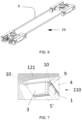
- the horizontal movement means 26, shown in detail in Figure 6 comprise trolleys 6 in each self-supporting unit 4 and guides 7 embedded on the first level 1 and on the second level 2, with the trolley 6 collaborating with the respective guide 7 for the horizontal movement of the corresponding self-supporting unit 4 along the first level 1 and/or the second level 2.
- the first level 1 and the second level 2 have substantially flat surfaces, the guides 7 being arranged embedded therein.
- each self-supporting unit 4 is supported by between 10 and 22 trolleys if the self-supporting unit 4 is oriented longitudinally towards the pitch 120, the number of trolleys preferably being between 4 and 12 if the self-supporting unit 4 is configured in the transverse direction of the pitch 120.
- the horizontal movement means 26 comprise motors, control means, and the elements needed to be able to carry out the synchronized horizontal movement of each self-supporting unit 4, and the description of such means is not considered necessary.
- the vertical movement means 15 comprise a first platform 5' which can be moved in the pit 3 between an initial position in which it is aligned with the first level 1, closing the pit 3, and an end position, and a second platform 14 which can be moved in the pit 3 between an initial position in which it is aligned with the first platform 5' when said first platform 5' is located in the end position and an end position, in which the second platform 14 is aligned with the second level 2.
- the path of the first platform 5' is smaller than the path of the second platform 14.
- the pit 3 comprises a first chamber 3a where the first platform 5' is housed and a second chamber 3b where the second platform 14 is housed, with both chambers 3a and 3b being arranged adjacent to and in communication with one another.
- the first chamber 3a is arranged adjacent to one side of the pitch 120 and the second chamber 3b extends at least partially under stands 121 of the sports stadium 110, as shown in the figure or under the pitch 120. Arranging part of the pit 3 under the stands without affecting the structure of the stands, or in other embodiments under the playing space without affecting the second level 2, is thereby enabled.
- each platform 5' and 14 must withstand are independent of one another, simplifying the facility given that since the first platform 5' acts like a closure of the pit 3, it has to withstand higher loads than the second platform 14 depending on the type of events to be held on the first level 1.
- the vertical movement means 15 comprise the lifting devices 18 which support each platform 5' and 14 and the corresponding self-supporting unit 4 which is arranged on the same, and move them vertically along the pit 3.
- the lifting devices 18 can also be mechanical, such as spiralifts or linear spindles and/or hydraulic, such as hydraulic cylinders, being moved in a synchronized manner in all cases both in loading and in position.
- the hydraulic lifting devices can further comprise the corresponding tanks, pumps, electric motors, etc., and their description is not considered necessary given that they are known in the state of the art.
- both platforms 5' and 14 are substantially flat and comprise guides 7 similar to the guides of the horizontal movement means 26 described above, such that when the first platform 5' is in the initial position, closing access to the pit 3, the guides 7 of the first platform 5' are arranged aligned with the guides 7 embedded on the first level 1 such that the trolleys 6 of each self-supporting unit 4 can displace in a guided manner each self-supporting unit 4 along the first level 1 until being positioned in the first platform 5'.
- the guides 7 of both platforms 5' and 14 are aligned so that the self-supporting unit 4 can be displaced horizontally between both.
- the first level 1 is supported by a structure 17 the span of which is greater than the length of the pitch 120.
- the support structure 17 supports the entire first level 1, being capable of overcoming the large spans existing between the sides and bottoms of the pitch, without the need for intermediate columns.
- the structure 17 is based on a spatial mesh system, made up of bars and balls, in an arch shape and studs following the arch to the lower side supports; and open at the lower part to house the set of elements and components of the agronomic systems to care for the turf on the second level 2.
- the support structure 17 which is conceived for the vertical separation between the two levels 1 and 2 to be as small as possible but enough to house the necessary edge that makes it possible to support the first level 1 with the events performed on it and to also allow events on the second level 2 without problems with visual ergonomics.
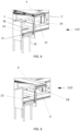
- the sports stadium 110 further comprises side guides 10 and 11 in the pit 3 and on each platform 5' and 14 which collaborate with one another in the guided vertical movement of the respective platform 5' and 14 along the pit 3, as shown in Figures 5 and 7 .
- the guides 11 are arranged on the sides of the respective platform 5' and 14.
- the sports stadium 110 further comprises retaining means 9 for retaining the platform 5' that closes the pit 3, the purpose being to retain the platform 5' in a locking position, the locking position being the position in which the platform 5' is aligned with the self-supporting units 4 on the first level 1, closing access to the pit 3 (also referred to as the initial position).
- the retaining means 9 shown in detail in Figures 3 and 4 are arranged at least partially embedded in the pit 3, in particular in the walls of the pit 3, and are configured to be moved between a retracted situation (shown in particular in Figures 3(a) and 3(b) ) in which the platform 5' can move vertically along the pit 3 and an extended position (shown in Figures 3(c) and 4 ), in which they block the platform 5' in the locking position which coincides with the initial position of the platform 5'.
- the retaining means 9 have to withstand the weight of the loads deposited on the platform 5' when it is in the locking position.
- the sports stadium 110 can include retaining means to retain the first platform 5' in its end position, and/or the second platform 14 in its initial and/or end position.
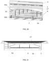
- the first level 1 is supported on the support structure 17 and on intermediate columns 16 each of which comprises a fixed part 16a and a mobile part 16b fixed to the second level 2.
- the mobile part 16b is arranged retracted in a non-working position; preferably, it can be deployed from the non-working position to a working position in which is connected to the corresponding fixed part 16a forming an intermediate column 16 to reinforce the first level 1 when the activities to be held on the first level 1, for example concerts, require this.
- the mobile part 16b can be deployed by means of irreversible mechanical linear spindles or other known lifting systems.
- the self-supporting units 4 are separated from one another by a certain distance to treat their joints in their end storage position on the second level 2, with the intermediate columns 16 being arranged between those gaps.
- Another aspect of the invention relates to a method for converting a sports stadium 110 as defined above into a multi-space, multifunctional infrastructure.
- the method comprises the following steps carried out sequentially:
- the trolleys 6 are operated such that they horizontally displace the self-supporting unit 4 guided along the first level 1 until positioning it on the platform 5' which, at that time, is in the initial position or locking position retained by the retaining means 9.
- the self-supporting unit 4 When the self-supporting unit 4 is centered on the platform 5', it moves downwards, operated by the respective actuation means 18 to the end position in which it is aligned with the second platform 14.
- the self-supporting unit 4 is horizontally transferred by means of the trolleys 6 from the first platform 5' to the second platform 14, subsequently being lowered by means of the actuation means of the second platform 15 to the end position in which the second platform 14 is aligned with the second level 2. In that position, the trolleys 6 are operated to displace the self-supporting unit 4 from the second platform 14 to the storage position on the second level 2.
- the movement of the first platform 5' is smaller than the movement of the second platform 14.
- the self-supporting units 4 are moved sequentially from the first level 1 to the second level 2 where they are stored. When the pitch 120 is to be re-positioned on the first level 1, the process described above is inverted.
- a method of converting a sports stadium into a multifunctional facility in a rapid and optimized manner is thereby obtained. Furthermore, a more rapid facility can be obtained, given that while the second platform 14 vertically moves the self-supporting unit 4 towards the second level 2, the first platform 5' can vertically move the self-supporting unit 4.
Landscapes
- Engineering & Computer Science (AREA)
- Architecture (AREA)
- Civil Engineering (AREA)
- Structural Engineering (AREA)
- Physics & Mathematics (AREA)
- Electromagnetism (AREA)
- Road Paving Structures (AREA)
Abstract
Description
- The present invention relates to sports stadiums, which are preferably already built in consolidated urban centers and are understood to mean facilities which combine a large central space for sports games and other events with a large seating capacity for spectators, and it also relates to a method for converting a sports stadium into a multi-space, multifunctional infrastructure.
- While technical solutions for converting stadiums into multifunctional facilities are known today, it is also true that most of them focus on newly built stadiums, are very complex and expensive, and do not focus on caring for and maintaining the turf in a controlled environment. Furthermore, most of them would not be valid for stadiums that are already built and operating.
- International application
WO2021/186096A1 discloses a system for converting stadiums into multifunctional infrastructures by removing the pitch and storing it in a pit. The vertical storage of the self-supporting units into which the pitch is divided involves building a deep pit, in addition to complicating the maintenance of the stored turf. - International application
WO2022/106570A1 discloses an installation which comprises multiple movable turf modules that are movable between an installed state and a storage state, and a storage system is with a module storage chamber configured to accommodate the turf modules when in the storage state and with sets of movable support beams configured to support the turf modules. The module storage chamber comprises two opposite guide walls, each guide wall comprising horizontal beam guides configured to guide support beams in horizontal directions. The module storage chamber vertically moves, and retractable beam lift moves support beams vertically. Retractable storage support supports the support beams. The module storage system comprises a support beam storage configured to store the sets of support beams. - US applications
US2014/0123566A1 andUS2015/0354240A1 disclose a sports stadium according to the preamble ofclaim 1. - The object of the invention is to provide a sports stadium and a method for converting a sports stadium into a multi-space, multifunctional infrastructure, as defined in the claims.
- One aspect relates to the sports stadium comprising a first level on which, in a playing position, a pitch is arranged, divided into a plurality of self-supporting units, horizontal movement means for horizontally moving each self-supporting unit on the first level, a pit in communication with the first level, and vertical movement means for vertically moving each self-supporting unit in the pit.
- The sports stadium comprises a second level arranged under the first level which houses, in a storage position, the plurality of self-supporting units which form the pitch, the second level being arranged in communication with the first level through the pit, each self-supporting unit being moved horizontally along the first level and/or the second level through the horizontal movement means and between both levels through the vertical movement means. The vertical movement means comprise a first platform which can be moved in the pit between a position in which it is aligned with the first level, closing the pit, and an end position, and a second platform which can be moved in the pit between an initial position in which it is aligned with the first platform when said first platform is located in the end position and an end position, in which the second platform is aligned with the second level.
- Another aspect of the invention relates to the method for converting the sports stadium into a multi-space, multifunctional infrastructure comprising the following steps carried out sequentially:
- horizontally moving each self-supporting unit through horizontal transport means along the first level until being arranged on the vertical movement means;
- vertically moving the self-supporting unit upon actuation of the vertical movement means to an end position; and
- horizontally moving the self-supporting unit through the horizontal movement means along the second level to its storage position,
- wherein after being moved horizontally along the first level, the self-supporting unit is supported on a first platform vertically moving along a first path to an end position, then moving horizontally to a second platform which in turn will vertically move the self-supporting unit along a second path, and finally the self-supporting unit is moved horizontally on the second level to a storage position.
- Any sports stadium can thereby be converted into a multi-space, multifunctional infrastructure by removing the pitch and storing it in an automated manner on a lower level built for that purpose below the area of the pitch and taking up about the same surface area as said pitch. When the upper level where the pitch is initially located for other activities is required to be used, the self-supporting units are taken to the second level where, in addition to storing the turf of the pitch, they can be properly cared for. This facility can be implemented not only in newly built sports stadiums but also in sports stadiums that are already built, such that they can be reversibly converted into multifunctional infrastructures.
- A facility is obtained more rapidly, given that while the second platform vertically moves the self-supporting unit towards the second level, the first platform can vertically move a self-supporting unit. Since the paths and loads to be withstood by each platform are independent of one another, the facility is simplified given that since the first platform acts like a closure of the pit, it has to withstand higher loads than the second platform depending on the type of events to be held on the first level. Moreover, arranging part of the pit under the stands without affecting the structure of said stands, or under the playing space without affecting the second level, is enabled.
- These and other advantages and features of the invention will become apparent in view of the figures and detailed description of the invention.
-
-
Figure 1 shows a schematic perspective view of an embodiment of a sports stadium according to the invention, comprising a pitch divided into self-supporting units. -
Figure 2 shows a detail of the sports stadium shown inFigure 1 , where horizontal movement means of the self-supporting units are shown. -
Figure 3 shows a detail of retaining means of the vertical movement means shown inFigure 1 . -
Figure 4 shows a partial sectioned view of the sports stadium shown inFigure 1 , where the retaining means shown in detail inFigure 3 are in the locking mode. -
Figure 5 shows in detail a platform of the vertical movement means of the sports stadium shown inFigure 1 . -
Figure 6 shows in detail trolleys of the horizontal movement means of the sports stadium shown inFigure 1 . -
Figure 7 shows a detail of the pit of the sports stadium shown inFigure 1 . -
Figures 8 to 18 sequentially show the transfer of a self-supporting unit from the playing position on the first level to the storage position on the second level of the sports stadium shown inFigure 1 . -
Figure 19 shows another embodiment of the sports stadium according to the invention. -
Figure 20 shows a detail of the sports stadium shown inFigure 19 . -
Figure 21 shows a side view of the sports stadium shown inFigure 19 . - The
sports stadium 110 according to the invention comprises afirst level 1 on which, in a playing position, apitch 120 is arranged, divided into a plurality of self-supportingunits 4, horizontal movement means 26 for horizontally moving each self-supportingunit 4 on thefirst level 1, apit 3 in communication with thefirst level 1, and vertical movement means 15 for vertically moving each self-supportingunit 4 in thepit 3. In the embodiments shown in the figures, thepit 3 is located on one side of thepitch 120. In another embodiment, thepit 3 is located on one side of thepitch 120 but extends below thepitch 120, invading the space occupied by the pitch up to a width close or equal to the width of a self-supportingunit 4. In another embodiment, thepit 3 is located in the pitch in an intermediate position, thepit 3 being aligned with the end position of the self-supportingunit 4, above same, such that this self-supportingunit 4 requires only a vertical movement to start its storage maneuver. - The fact that the
pit 3 is built on one side of the pitch and does not invade same has the advantage that all the self-supportingunits 4 can be the same since in use, they will all be supported on firm ground and without any difference in support between any of them. The fact that thepit 3 is built on one side of the pitch, but invading it only up to the width of one of self-supportingunits 4 has the advantage that the stands are not affected. In both cases, the movements of all the self-supporting units in the same horizontal direction in their storing or extraction sequences are facilitated, and it will allow thesupport structure 17 of thefirst level 1 to be spatially continuous and not have to be cut, and therefore reinforced, by a pit in an intermediate area thereof. - In the event that the pit is built on one of the sides of the pitch, without invading it or partially invading it, one of the preferred embodiments of the invention will seek for the position of the pit to be slightly moved to the outside of the pitch with respect to the self-supporting unit located above same, for the purpose of allowing slight horizontal translational movement of this self-supporting unit to more securely close the turf joint with respect to the next self-supporting unit, and with it leading the self-supporting unit above the pit to be, in match mode, moved slightly towards the pitch, resting on the slab at the inner edge thereof, and on the scale at the other three.
- Furthermore, the
sports stadium 110 comprises asecond level 2 arranged under thefirst level 1 which houses, in a storage position, the plurality of self-supportingunits 4 which form thepitch 120. Thesecond level 2 is arranged substantially parallel to thefirst level 1 and facing saidfirst level 1. Thesecond level 2 is in communication with thefirst level 1 through thepit 3, each self-supportingunit 4 being moved horizontally along thefirst level 1 and/or thesecond level 2 through the horizontal movement means 26 and between bothlevels - Each self-supporting
unit 4 comprises layers of field, a natural or artificial turf and irrigation means not shown in detail in the figures. Thepitch 120 is divided longitudinally or transversely into self-supportingunits 4. - In one embodiment, each self-supporting
unit 4 has a length at least equal to the total length of thepitch 120, said length being preferably equal to the smaller side of thepitch 120. - Preferably, the number of self-supporting
units 4 configuring thepitch 120 is comprised between five and eight when said self-supportingunits 4 are arranged longitudinally along the length of thepitch 120. Preferably, each self-supportingunit 4 has dimensions of 144 m in length and between about 9 and 12 m in width. - In another embodiment not shown in the figures, in which the self-supporting
units 4 are arranged transversely along the length of thepitch 120, the number of self-supporting units configuring thepitch 120 is preferably comprised between 8 and 14, the dimension of each self-supportingunit 4 being preferably up to 70 m in length and between 8 and 13 m in width, respectively. - The
second level 2 is sized such that it enables the storage of all the self-supportingunits 4 arranged forming thepitch 120 on thesecond level 2. In one embodiment, the dimensions ofsecond level 2 are such that it allows housing all the self-supportingunits 4 separated from one another by a certain distance to enable treating joints of each self-supportingunit 4. In another embodiment, the self-supportingunits 4 are stored on thesecond level 2 forming thepitch 120 without separations between them. When it becomes necessary to treat the joints, each self-supportingunit 4 could be displaced sequentially a horizontal distance to separate it from its adjacent one and the joint could be treated if needed, or the entire turf could be cared for in monoblock mode. - The horizontal movement means 26, shown in detail in
Figure 6 , comprisetrolleys 6 in each self-supportingunit 4 andguides 7 embedded on thefirst level 1 and on thesecond level 2, with thetrolley 6 collaborating with therespective guide 7 for the horizontal movement of the corresponding self-supportingunit 4 along thefirst level 1 and/or thesecond level 2. Thefirst level 1 and thesecond level 2 have substantially flat surfaces, theguides 7 being arranged embedded therein. - In one embodiment, the
guides 7 can be rails (as shown in the figures) or inductive guiding systems. Preferably, each self-supportingunit 4 is supported by between 10 and 22 trolleys if the self-supportingunit 4 is oriented longitudinally towards thepitch 120, the number of trolleys preferably being between 4 and 12 if the self-supportingunit 4 is configured in the transverse direction of thepitch 120. - The horizontal movement means 26 comprise motors, control means, and the elements needed to be able to carry out the synchronized horizontal movement of each self-supporting
unit 4, and the description of such means is not considered necessary. - In one embodiment of the
sports stadium 110 according to the invention, shown inFigures 1 to 18 , the vertical movement means 15 comprise a first platform 5' which can be moved in thepit 3 between an initial position in which it is aligned with thefirst level 1, closing thepit 3, and an end position, and asecond platform 14 which can be moved in thepit 3 between an initial position in which it is aligned with the first platform 5' when said first platform 5' is located in the end position and an end position, in which thesecond platform 14 is aligned with thesecond level 2. Preferably, the path of the first platform 5' is smaller than the path of thesecond platform 14. - The
pit 3 comprises afirst chamber 3a where the first platform 5' is housed and asecond chamber 3b where thesecond platform 14 is housed, with bothchambers first chamber 3a is arranged adjacent to one side of thepitch 120 and thesecond chamber 3b extends at least partially under stands 121 of thesports stadium 110, as shown in the figure or under thepitch 120. Arranging part of thepit 3 under the stands without affecting the structure of the stands, or in other embodiments under the playing space without affecting thesecond level 2, is thereby enabled. Furthermore, the paths and the loads that eachplatform 5' and 14 must withstand are independent of one another, simplifying the facility given that since the first platform 5' acts like a closure of thepit 3, it has to withstand higher loads than thesecond platform 14 depending on the type of events to be held on thefirst level 1. - The vertical movement means 15 comprise the
lifting devices 18 which support eachplatform 5' and 14 and the corresponding self-supportingunit 4 which is arranged on the same, and move them vertically along thepit 3. In this embodiment, thelifting devices 18 can also be mechanical, such as spiralifts or linear spindles and/or hydraulic, such as hydraulic cylinders, being moved in a synchronized manner in all cases both in loading and in position. The hydraulic lifting devices can further comprise the corresponding tanks, pumps, electric motors, etc., and their description is not considered necessary given that they are known in the state of the art. - Moreover, both
platforms 5' and 14 are substantially flat and comprise guides 7 similar to the guides of the horizontal movement means 26 described above, such that when the first platform 5' is in the initial position, closing access to thepit 3, theguides 7 of the first platform 5' are arranged aligned with theguides 7 embedded on thefirst level 1 such that thetrolleys 6 of each self-supportingunit 4 can displace in a guided manner each self-supportingunit 4 along thefirst level 1 until being positioned in the first platform 5'. When thesecond platform 14 is in the initial position and the first platform 5' is in the end position, theguides 7 of bothplatforms 5' and 14 are aligned so that the self-supportingunit 4 can be displaced horizontally between both. - Moreover, the
first level 1 is supported by astructure 17 the span of which is greater than the length of thepitch 120. Thesupport structure 17 supports the entirefirst level 1, being capable of overcoming the large spans existing between the sides and bottoms of the pitch, without the need for intermediate columns. Thestructure 17 is based on a spatial mesh system, made up of bars and balls, in an arch shape and studs following the arch to the lower side supports; and open at the lower part to house the set of elements and components of the agronomic systems to care for the turf on thesecond level 2. Thesupport structure 17 which is conceived for the vertical separation between the twolevels first level 1 with the events performed on it and to also allow events on thesecond level 2 without problems with visual ergonomics. - In the embodiment shown in the figure, the
sports stadium 110 further comprises side guides 10 and 11 in thepit 3 and on eachplatform 5' and 14 which collaborate with one another in the guided vertical movement of therespective platform 5' and 14 along thepit 3, as shown inFigures 5 and7 . Theguides 11 are arranged on the sides of therespective platform 5' and 14. - In the embodiments shown in the figures, the
sports stadium 110 further comprises retaining means 9 for retaining the platform 5' that closes thepit 3, the purpose being to retain the platform 5' in a locking position, the locking position being the position in which the platform 5' is aligned with the self-supportingunits 4 on thefirst level 1, closing access to the pit 3 (also referred to as the initial position). The retaining means 9 shown in detail inFigures 3 and 4 are arranged at least partially embedded in thepit 3, in particular in the walls of thepit 3, and are configured to be moved between a retracted situation (shown in particular inFigures 3(a) and 3(b) ) in which the platform 5' can move vertically along thepit 3 and an extended position (shown inFigures 3(c) and 4 ), in which they block the platform 5' in the locking position which coincides with the initial position of the platform 5'. - The retaining means 9 have to withstand the weight of the loads deposited on the platform 5' when it is in the locking position.
- In another embodiment, the
sports stadium 110 can include retaining means to retain the first platform 5' in its end position, and/or thesecond platform 14 in its initial and/or end position. - Moreover, in the embodiment shown in
Figures 19 to 21 , thefirst level 1 is supported on thesupport structure 17 and onintermediate columns 16 each of which comprises afixed part 16a and amobile part 16b fixed to thesecond level 2. Themobile part 16b is arranged retracted in a non-working position; preferably, it can be deployed from the non-working position to a working position in which is connected to the correspondingfixed part 16a forming anintermediate column 16 to reinforce thefirst level 1 when the activities to be held on thefirst level 1, for example concerts, require this. Themobile part 16b can be deployed by means of irreversible mechanical linear spindles or other known lifting systems. - In
Figures 19 to 21 , the self-supportingunits 4 are separated from one another by a certain distance to treat their joints in their end storage position on thesecond level 2, with theintermediate columns 16 being arranged between those gaps. - Another aspect of the invention relates to a method for converting a
sports stadium 110 as defined above into a multi-space, multifunctional infrastructure. - The method comprises the following steps carried out sequentially:
- horizontally moving each self-supporting
unit 4 through the horizontal transport means 26 along thefirst level 1 until being arranged on the vertical movement means 15; - vertically moving the self-supporting
unit 4 upon actuation of the vertical movement means 5 to an end position; and - horizontally moving the self-supporting
unit 4 through the horizontal movement means 26 along thesecond level 2 to its storage position. - In particular, when the
pitch 120 must be stored on thesecond level 2, thetrolleys 6 are operated such that they horizontally displace the self-supportingunit 4 guided along thefirst level 1 until positioning it on the platform 5' which, at that time, is in the initial position or locking position retained by the retaining means 9. - When the self-supporting
unit 4 is centered on the platform 5', it moves downwards, operated by the respective actuation means 18 to the end position in which it is aligned with thesecond platform 14. The self-supportingunit 4 is horizontally transferred by means of thetrolleys 6 from the first platform 5' to thesecond platform 14, subsequently being lowered by means of the actuation means of thesecond platform 15 to the end position in which thesecond platform 14 is aligned with thesecond level 2. In that position, thetrolleys 6 are operated to displace the self-supportingunit 4 from thesecond platform 14 to the storage position on thesecond level 2. Preferably, the movement of the first platform 5' is smaller than the movement of thesecond platform 14. The self-supportingunits 4 are moved sequentially from thefirst level 1 to thesecond level 2 where they are stored. When thepitch 120 is to be re-positioned on thefirst level 1, the process described above is inverted. - A method of converting a sports stadium into a multifunctional facility in a rapid and optimized manner is thereby obtained. Furthermore, a more rapid facility can be obtained, given that while the
second platform 14 vertically moves the self-supportingunit 4 towards thesecond level 2, the first platform 5' can vertically move the self-supportingunit 4. - The described features of the sports stadium in any of its embodiments are valid for the method described in any of its embodiments and vice versa.
Claims (13)
- Sports stadium comprising a first level (1) on which, in a playing position, a pitch (120) is arranged, divided into a plurality of self-supporting units (4), and a second level (2) arranged under the first level (1) which houses, in a storage position, the plurality of self-supporting units (4) which form the pitch (120), the second level (2) being arranged in communication with the first level (1) through a pit (3), each self-supporting unit (4) being moved horizontally along the first level (1) and/or the second level (2) through horizontal movement means (26) and between both levels (1,2) through vertical movement means (15), characterized in that the vertical movement means (15) comprise a first platform (5') which can be moved in the pit (3) between a position in which it is aligned with the first level (1), closing the pit (3), and an end position, and a second platform (14) which can be moved in the pit (3) between an initial position in which it is aligned with the first platform (5') when said first platform (5') is located in the end position, and an end position in which the second platform (14) is aligned with the second level (2).
- Sports stadium according to the preceding claim, wherein the pit (3) comprises a first chamber (3a) where the first platform (5') is housed and a second chamber (3b) where the second platform (14) is housed, with both chambers (3a, 3b) being arranged adjacent to and in communication with one another, such that the first chamber (3a) is arranged adjacent to one side of the pitch (120) and the second chamber (3b) extends at least partially under stands (121) of the sports stadium (110) or under the pitch (120).
- Sports stadium according to any of the preceding claims, wherein each platform (5',14) includes the horizontal movement means (26) arranged such that they are aligned with the horizontal movement means (26) arranged on the first level (1) and on the second level (2), respectively, when the platform (5', 14) is arranged aligned, respectively, with the first level (1) and/or with the second level (2).
- Sports stadium according to any of the preceding claims, wherein the vertical movement means (15) comprise lifting devices (18) which support the corresponding platform (5',14) and move it vertically, said lifting devices (18) being mechanical and/or hydraulic.
- Sports stadium according to any of the preceding claims, comprising retaining means (9) for retaining the respective platform (5', 14), the retaining means (9) being arranged at least partially embedded in the pit (3) and configured to be moved between a retracted situation in which the platform (5',14) can move vertically along the pit (3), and an extended position in which they block the respective platform (5', 14) in its initial and/or end positions, respectively, said retaining means (9) being mechanically and/or hydraulically operated.
- Sports stadium according to any of the preceding claims, comprising guides (10,11) in the pit (3) and in the respective platform (5',14) which collaborate with one another for the guided vertical movement of each platform (5',14) along the pit (3).
- Sports stadium according to any of the preceding claims, wherein the second level (2) has a surface at least equal to the surface corresponding to the pitch (120) such that it enables the storage of the self-supporting units (4) forming the pitch (120) on the second level (2).
- Sports stadium according to the preceding claim, wherein the second level (2) has a surface above the surface corresponding to the pitch (120) such that it enables the storage of the plurality of the self-supporting units (4) separated from one another for maintenance thereof.
- Sports stadium according to any of the preceding claims, wherein the horizontal movement means (26) comprise at least one trolley (6) in each self-supporting unit (4) and guides (7) embedded on the first level (1), on the second level (2), and in the corresponding platform (5',14), respectively, the trolley (6) collaborating with the respective guide (7) for the horizontal movement of the corresponding self-supporting unit (4).
- Sports stadium according to any of the preceding claims, comprising a support structure (17) the span of which is greater than the length of the pitch (120), and a plurality of intermediate columns (16) each of which comprises a fixed part (16a) fixed to the first level (1) and a mobile part (16b) fixed to the second level (2), the mobile part (16b) being arranged retracted in a non-working position, and being deployable from the non-working position to a working position in which it is connected to the corresponding fixed part (16a) forming an intermediate column (16) to reinforce the first level (1).
- Sports stadium according to any of the preceding claims, wherein each self-supporting unit (4) has a length at least equal to the length of the smaller side of the pitch (120).
- Sports stadium according to any of the preceding claims, wherein each self-supporting unit (4) comprises layers of field, a natural or artificial turf and irrigation means.
- Method for converting a sports stadium according to any of the preceding claims into a multi-space, multifunctional infrastructure, comprising the steps of horizontally moving each self-supporting unit (4) through the horizontal movement means (26) along the first level (2) until being arranged on the vertical movement means (15), vertically moving the self-supporting unit (4), and horizontally moving the self-supporting unit (4) from the platform (5',14) until positioning it in a storage position on the second level (2), characterized in that after being moved horizontally along the first level (1), the self-supporting unit (4) is supported on a first platform (5') vertically moving along a first path to an end position, then moving horizontally to a second platform (14) which in turn will vertically move the self-supporting unit (4) along a second path, and finally the self-supporting unit (4) is moved horizontally on the second level (2) to a storage position.
Applications Claiming Priority (2)
| Application Number | Priority Date | Filing Date | Title |
|---|---|---|---|
| ES202230684A ES2959278A1 (en) | 2022-07-26 | 2022-07-26 | Sports stadium and method of converting a sports stadium into a multi-space multifunctional infrastructure |
| PCT/ES2023/070484 WO2024023386A1 (en) | 2022-07-26 | 2023-07-26 | Sports stadium and method for converting a sports stadium into a multi-space, multifunctional infrastructure |
Publications (2)
| Publication Number | Publication Date |
|---|---|
| EP4563771A1 true EP4563771A1 (en) | 2025-06-04 |
| EP4563771B1 EP4563771B1 (en) | 2026-01-28 |
Family
ID=88093804
Family Applications (1)
| Application Number | Title | Priority Date | Filing Date |
|---|---|---|---|
| EP23772546.0A Active EP4563771B1 (en) | 2022-07-26 | 2023-07-26 | Sports stadium and method for converting a sports stadium into a multi-space, multifunctional infrastructure |
Country Status (5)
| Country | Link |
|---|---|
| US (1) | US20250179821A1 (en) |
| EP (1) | EP4563771B1 (en) |
| ES (2) | ES2959278A1 (en) |
| MX (1) | MX2025000984A (en) |
| WO (1) | WO2024023386A1 (en) |
Citations (1)
| Publication number | Priority date | Publication date | Assignee | Title |
|---|---|---|---|---|
| US20140123566A1 (en) | 2011-06-30 | 2014-05-08 | Nutcracker Solutions As | Sports stadium with removable turf field |
Family Cites Families (6)
| Publication number | Priority date | Publication date | Assignee | Title |
|---|---|---|---|---|
| NL1001005C2 (en) * | 1995-08-18 | 1997-02-20 | Frans Hock | Multifunctional construction. |
| US8033061B2 (en) * | 2002-06-27 | 2011-10-11 | Hrazdjira Guenter | Sales and presentation area with rotatably mounted annular region divided into vertically movable ring segments |
| WO2014102321A1 (en) * | 2012-12-30 | 2014-07-03 | Nutcracker Solutions As | Sports stadium having removable field |
| WO2015024985A2 (en) * | 2013-08-20 | 2015-02-26 | Nutcracker Solutions As | Sports stadium with movable turf modules and associated method |
| ES2854498B2 (en) * | 2020-03-19 | 2022-09-15 | Sener Ing & Sist | SYSTEM TO REVERSIBLY CONVERT STADIUMS INTO MULTIFUNCTIONAL INFRASTRUCTURES |
| WO2022106570A1 (en) * | 2020-11-19 | 2022-05-27 | Nutcracker Solutions As | A turf sports facility |
-
2022
- 2022-07-26 ES ES202230684A patent/ES2959278A1/en not_active Withdrawn
-
2023
- 2023-07-26 WO PCT/ES2023/070484 patent/WO2024023386A1/en not_active Ceased
- 2023-07-26 EP EP23772546.0A patent/EP4563771B1/en active Active
- 2023-07-26 ES ES23772546T patent/ES3064402T3/en active Active
-
2025
- 2025-01-24 MX MX2025000984A patent/MX2025000984A/en unknown
- 2025-01-24 US US19/036,211 patent/US20250179821A1/en active Pending
Patent Citations (1)
| Publication number | Priority date | Publication date | Assignee | Title |
|---|---|---|---|---|
| US20140123566A1 (en) | 2011-06-30 | 2014-05-08 | Nutcracker Solutions As | Sports stadium with removable turf field |
Also Published As
| Publication number | Publication date |
|---|---|
| MX2025000984A (en) | 2025-03-07 |
| ES3064402T3 (en) | 2026-04-24 |
| EP4563771B1 (en) | 2026-01-28 |
| ES2959278A1 (en) | 2024-02-22 |
| WO2024023386A1 (en) | 2024-02-01 |
| US20250179821A1 (en) | 2025-06-05 |
Similar Documents
| Publication | Publication Date | Title |
|---|---|---|
| US12473739B2 (en) | System for reversibly converting stadiums into multifunctional infrastructure | |
| JP7735303B2 (en) | Automated storage system with storage tower in isolation enclosure | |
| US8977383B2 (en) | Modular storage system | |
| EP0654571B1 (en) | Zone module construction method of steel structure construction | |
| RU2102570C1 (en) | Motor vehicle parking facility | |
| JP2023519893A (en) | Autosave tower with multiple rows | |
| NZ573185A (en) | A temporary bridge having a number bridge elements stackable in a first position and deployable side-by-side in a second position | |
| JP7813237B2 (en) | Automated Storage and Retrieval System | |
| JP2022537917A (en) | Automated containment and retrieval system with barriers | |
| SG191363A1 (en) | Parking facility | |
| EP4563771B1 (en) | Sports stadium and method for converting a sports stadium into a multi-space, multifunctional infrastructure | |
| JP2020506136A (en) | Modular automated warehouse for storing industrial products | |
| CA2956506C (en) | Honeycomb storage system and commissioning device for a honeycomb storage system | |
| EP3704002B1 (en) | Flächenspeicher sowie verfahren zur förderung von fahrzeugkarosserien oder fahrzeugkarosserieaufnahmen | |
| JPH10184061A (en) | Mechanical underground parking | |
| EP3110724B1 (en) | Warehouse | |
| EP1828507A1 (en) | Storage system | |
| RU2466077C2 (en) | Device related to transportation system | |
| KR200275312Y1 (en) | A charnel house | |
| JPH0598830A (en) | One-empty-space type multistage parallel sky parking system | |
| JPH05118156A (en) | Multi-storied parking system | |
| CN118110365A (en) | Construction method of three-dimensional comprehensive expansion stage system | |
| JPH0598831A (en) | One-empty-space type multistage parallel sky paring system | |
| IL98360A (en) | Method and apparatus for compactly storing and retrieving objects | |
| CZ217796A3 (en) | Automated circular rack-like parking place |
Legal Events
| Date | Code | Title | Description |
|---|---|---|---|
| STAA | Information on the status of an ep patent application or granted ep patent |
Free format text: STATUS: UNKNOWN |
|
| STAA | Information on the status of an ep patent application or granted ep patent |
Free format text: STATUS: THE INTERNATIONAL PUBLICATION HAS BEEN MADE |
|
| PUAI | Public reference made under article 153(3) epc to a published international application that has entered the european phase |
Free format text: ORIGINAL CODE: 0009012 |
|
| STAA | Information on the status of an ep patent application or granted ep patent |
Free format text: STATUS: REQUEST FOR EXAMINATION WAS MADE |
|
| 17P | Request for examination filed |
Effective date: 20250226 |
|
| AK | Designated contracting states |
Kind code of ref document: A1 Designated state(s): AL AT BE BG CH CY CZ DE DK EE ES FI FR GB GR HR HU IE IS IT LI LT LU LV MC ME MK MT NL NO PL PT RO RS SE SI SK SM TR |
|
| GRAP | Despatch of communication of intention to grant a patent |
Free format text: ORIGINAL CODE: EPIDOSNIGR1 |
|
| STAA | Information on the status of an ep patent application or granted ep patent |
Free format text: STATUS: GRANT OF PATENT IS INTENDED |
|
| DAV | Request for validation of the european patent (deleted) | ||
| DAX | Request for extension of the european patent (deleted) | ||
| INTG | Intention to grant announced |
Effective date: 20250909 |
|
| TPAC | Observations filed by third parties |
Free format text: ORIGINAL CODE: EPIDOSNTIPA |
|
| GRAS | Grant fee paid |
Free format text: ORIGINAL CODE: EPIDOSNIGR3 |
|
| GRAA | (expected) grant |
Free format text: ORIGINAL CODE: 0009210 |
|
| STAA | Information on the status of an ep patent application or granted ep patent |
Free format text: STATUS: THE PATENT HAS BEEN GRANTED |
|
| AK | Designated contracting states |
Kind code of ref document: B1 Designated state(s): AL AT BE BG CH CY CZ DE DK EE ES FI FR GB GR HR HU IE IS IT LI LT LU LV MC ME MK MT NL NO PL PT RO RS SE SI SK SM TR |
|
| REG | Reference to a national code |
Ref country code: CH Ref legal event code: F10 Free format text: ST27 STATUS EVENT CODE: U-0-0-F10-F00 (AS PROVIDED BY THE NATIONAL OFFICE) Effective date: 20260128 Ref country code: GB Ref legal event code: FG4D |
|
| REG | Reference to a national code |
Ref country code: DE Ref legal event code: R096 Ref document number: 602023011401 Country of ref document: DE |
|
| REG | Reference to a national code |
Ref country code: IE Ref legal event code: FG4D |
|
| REG | Reference to a national code |
Ref country code: ES Ref legal event code: FG2A Ref document number: 3064402 Country of ref document: ES Kind code of ref document: T3 Effective date: 20260424 |