EP4563256A1 - Induction heating device for metal sheet, processing equipment for metal sheet, and induction heating method for metal sheet - Google Patents
Induction heating device for metal sheet, processing equipment for metal sheet, and induction heating method for metal sheet Download PDFInfo
- Publication number
- EP4563256A1 EP4563256A1 EP22953205.6A EP22953205A EP4563256A1 EP 4563256 A1 EP4563256 A1 EP 4563256A1 EP 22953205 A EP22953205 A EP 22953205A EP 4563256 A1 EP4563256 A1 EP 4563256A1
- Authority
- EP
- European Patent Office
- Prior art keywords
- metal plate
- conductor member
- induction heating
- heating device
- plate
- Prior art date
- Legal status (The legal status is an assumption and is not a legal conclusion. Google has not performed a legal analysis and makes no representation as to the accuracy of the status listed.)
- Pending
Links
Images








Classifications
-
- F—MECHANICAL ENGINEERING; LIGHTING; HEATING; WEAPONS; BLASTING
- F27—FURNACES; KILNS; OVENS; RETORTS
- F27B—FURNACES, KILNS, OVENS OR RETORTS IN GENERAL; OPEN SINTERING OR LIKE APPARATUS
- F27B9/00—Furnaces through which the charge is moved mechanically, e.g. of tunnel type; Similar furnaces in which the charge moves by gravity
- F27B9/06—Furnaces through which the charge is moved mechanically, e.g. of tunnel type; Similar furnaces in which the charge moves by gravity heated without contact between combustion gases and charge; electrically heated
- F27B9/062—Furnaces through which the charge is moved mechanically, e.g. of tunnel type; Similar furnaces in which the charge moves by gravity heated without contact between combustion gases and charge; electrically heated electrically heated
- F27B9/067—Furnaces through which the charge is moved mechanically, e.g. of tunnel type; Similar furnaces in which the charge moves by gravity heated without contact between combustion gases and charge; electrically heated electrically heated heated by induction
-
- B—PERFORMING OPERATIONS; TRANSPORTING
- B21—MECHANICAL METAL-WORKING WITHOUT ESSENTIALLY REMOVING MATERIAL; PUNCHING METAL
- B21B—ROLLING OF METAL
- B21B1/00—Metal-rolling methods or mills for making semi-finished products of solid or profiled cross-section; Sequence of operations in milling trains; Layout of rolling-mill plant, e.g. grouping of stands; Succession of passes or of sectional pass alternations
- B21B1/22—Metal-rolling methods or mills for making semi-finished products of solid or profiled cross-section; Sequence of operations in milling trains; Layout of rolling-mill plant, e.g. grouping of stands; Succession of passes or of sectional pass alternations for rolling plates, strips, bands or sheets of indefinite length
- B21B1/24—Metal-rolling methods or mills for making semi-finished products of solid or profiled cross-section; Sequence of operations in milling trains; Layout of rolling-mill plant, e.g. grouping of stands; Succession of passes or of sectional pass alternations for rolling plates, strips, bands or sheets of indefinite length in a continuous or semi-continuous process
- B21B1/28—Metal-rolling methods or mills for making semi-finished products of solid or profiled cross-section; Sequence of operations in milling trains; Layout of rolling-mill plant, e.g. grouping of stands; Succession of passes or of sectional pass alternations for rolling plates, strips, bands or sheets of indefinite length in a continuous or semi-continuous process by cold-rolling, e.g. Steckel cold mill
-
- B—PERFORMING OPERATIONS; TRANSPORTING
- B21—MECHANICAL METAL-WORKING WITHOUT ESSENTIALLY REMOVING MATERIAL; PUNCHING METAL
- B21B—ROLLING OF METAL
- B21B45/00—Devices for surface or other treatment of work, specially combined with or arranged in, or specially adapted for use in connection with, metal-rolling mills
-
- B—PERFORMING OPERATIONS; TRANSPORTING
- B21—MECHANICAL METAL-WORKING WITHOUT ESSENTIALLY REMOVING MATERIAL; PUNCHING METAL
- B21B—ROLLING OF METAL
- B21B45/00—Devices for surface or other treatment of work, specially combined with or arranged in, or specially adapted for use in connection with, metal-rolling mills
- B21B45/004—Heating the product
-
- B—PERFORMING OPERATIONS; TRANSPORTING
- B21—MECHANICAL METAL-WORKING WITHOUT ESSENTIALLY REMOVING MATERIAL; PUNCHING METAL
- B21B—ROLLING OF METAL
- B21B45/00—Devices for surface or other treatment of work, specially combined with or arranged in, or specially adapted for use in connection with, metal-rolling mills
- B21B45/04—Devices for surface or other treatment of work, specially combined with or arranged in, or specially adapted for use in connection with, metal-rolling mills for de-scaling, e.g. by brushing
- B21B45/06—Devices for surface or other treatment of work, specially combined with or arranged in, or specially adapted for use in connection with, metal-rolling mills for de-scaling, e.g. by brushing of strip material
-
- C—CHEMISTRY; METALLURGY
- C21—METALLURGY OF IRON
- C21D—MODIFYING THE PHYSICAL STRUCTURE OF FERROUS METALS; GENERAL DEVICES FOR HEAT TREATMENT OF FERROUS OR NON-FERROUS METALS OR ALLOYS; MAKING METAL MALLEABLE, e.g. BY DECARBURISATION OR TEMPERING
- C21D1/00—General methods or devices for heat treatment, e.g. annealing, hardening, quenching or tempering
- C21D1/06—Surface hardening
- C21D1/09—Surface hardening by direct application of electrical or wave energy; by particle radiation
- C21D1/10—Surface hardening by direct application of electrical or wave energy; by particle radiation by electric induction
-
- C—CHEMISTRY; METALLURGY
- C21—METALLURGY OF IRON
- C21D—MODIFYING THE PHYSICAL STRUCTURE OF FERROUS METALS; GENERAL DEVICES FOR HEAT TREATMENT OF FERROUS OR NON-FERROUS METALS OR ALLOYS; MAKING METAL MALLEABLE, e.g. BY DECARBURISATION OR TEMPERING
- C21D1/00—General methods or devices for heat treatment, e.g. annealing, hardening, quenching or tempering
- C21D1/34—Methods of heating
- C21D1/42—Induction heating
-
- C—CHEMISTRY; METALLURGY
- C21—METALLURGY OF IRON
- C21D—MODIFYING THE PHYSICAL STRUCTURE OF FERROUS METALS; GENERAL DEVICES FOR HEAT TREATMENT OF FERROUS OR NON-FERROUS METALS OR ALLOYS; MAKING METAL MALLEABLE, e.g. BY DECARBURISATION OR TEMPERING
- C21D9/00—Heat treatment, e.g. annealing, hardening, quenching or tempering, adapted for particular articles; Furnaces therefor
- C21D9/46—Heat treatment, e.g. annealing, hardening, quenching or tempering, adapted for particular articles; Furnaces therefor for sheet metals
-
- C—CHEMISTRY; METALLURGY
- C21—METALLURGY OF IRON
- C21D—MODIFYING THE PHYSICAL STRUCTURE OF FERROUS METALS; GENERAL DEVICES FOR HEAT TREATMENT OF FERROUS OR NON-FERROUS METALS OR ALLOYS; MAKING METAL MALLEABLE, e.g. BY DECARBURISATION OR TEMPERING
- C21D9/00—Heat treatment, e.g. annealing, hardening, quenching or tempering, adapted for particular articles; Furnaces therefor
- C21D9/52—Heat treatment, e.g. annealing, hardening, quenching or tempering, adapted for particular articles; Furnaces therefor for wires; for strips ; for rods of unlimited length
- C21D9/54—Furnaces for treating strips or wire
- C21D9/56—Continuous furnaces for strip or wire
- C21D9/60—Continuous furnaces for strip or wire with induction heating
-
- F—MECHANICAL ENGINEERING; LIGHTING; HEATING; WEAPONS; BLASTING
- F27—FURNACES; KILNS; OVENS; RETORTS
- F27D—DETAILS OR ACCESSORIES OF FURNACES, KILNS, OVENS OR RETORTS, IN SO FAR AS THEY ARE OF KINDS OCCURRING IN MORE THAN ONE KIND OF FURNACE
- F27D11/00—Arrangement of elements for electric heating in or on furnaces
- F27D11/06—Induction heating, i.e. in which the material being heated, or its container or elements embodied therein, form the secondary of a transformer
-
- F—MECHANICAL ENGINEERING; LIGHTING; HEATING; WEAPONS; BLASTING
- F27—FURNACES; KILNS; OVENS; RETORTS
- F27D—DETAILS OR ACCESSORIES OF FURNACES, KILNS, OVENS OR RETORTS, IN SO FAR AS THEY ARE OF KINDS OCCURRING IN MORE THAN ONE KIND OF FURNACE
- F27D99/00—Subject matter not provided for in other groups of this subclass
- F27D99/0001—Heating elements or systems
- F27D99/0006—Electric heating elements or system
-
- H—ELECTRICITY
- H05—ELECTRIC TECHNIQUES NOT OTHERWISE PROVIDED FOR
- H05B—ELECTRIC HEATING; ELECTRIC LIGHT SOURCES NOT OTHERWISE PROVIDED FOR; CIRCUIT ARRANGEMENTS FOR ELECTRIC LIGHT SOURCES, IN GENERAL
- H05B6/00—Heating by electric, magnetic or electromagnetic fields
- H05B6/02—Induction heating
- H05B6/10—Induction heating apparatus, other than furnaces, for specific applications
-
- H—ELECTRICITY
- H05—ELECTRIC TECHNIQUES NOT OTHERWISE PROVIDED FOR
- H05B—ELECTRIC HEATING; ELECTRIC LIGHT SOURCES NOT OTHERWISE PROVIDED FOR; CIRCUIT ARRANGEMENTS FOR ELECTRIC LIGHT SOURCES, IN GENERAL
- H05B6/00—Heating by electric, magnetic or electromagnetic fields
- H05B6/02—Induction heating
- H05B6/10—Induction heating apparatus, other than furnaces, for specific applications
- H05B6/101—Induction heating apparatus, other than furnaces, for specific applications for local heating of metal pieces
- H05B6/103—Induction heating apparatus, other than furnaces, for specific applications for local heating of metal pieces multiple metal pieces successively being moved close to the inductor
- H05B6/104—Induction heating apparatus, other than furnaces, for specific applications for local heating of metal pieces multiple metal pieces successively being moved close to the inductor metal pieces being elongated like wires or bands
-
- H—ELECTRICITY
- H05—ELECTRIC TECHNIQUES NOT OTHERWISE PROVIDED FOR
- H05B—ELECTRIC HEATING; ELECTRIC LIGHT SOURCES NOT OTHERWISE PROVIDED FOR; CIRCUIT ARRANGEMENTS FOR ELECTRIC LIGHT SOURCES, IN GENERAL
- H05B6/00—Heating by electric, magnetic or electromagnetic fields
- H05B6/02—Induction heating
- H05B6/36—Coil arrangements
- H05B6/365—Coil arrangements using supplementary conductive or ferromagnetic pieces
-
- B—PERFORMING OPERATIONS; TRANSPORTING
- B21—MECHANICAL METAL-WORKING WITHOUT ESSENTIALLY REMOVING MATERIAL; PUNCHING METAL
- B21B—ROLLING OF METAL
- B21B1/00—Metal-rolling methods or mills for making semi-finished products of solid or profiled cross-section; Sequence of operations in milling trains; Layout of rolling-mill plant, e.g. grouping of stands; Succession of passes or of sectional pass alternations
- B21B1/22—Metal-rolling methods or mills for making semi-finished products of solid or profiled cross-section; Sequence of operations in milling trains; Layout of rolling-mill plant, e.g. grouping of stands; Succession of passes or of sectional pass alternations for rolling plates, strips, bands or sheets of indefinite length
- B21B2001/221—Metal-rolling methods or mills for making semi-finished products of solid or profiled cross-section; Sequence of operations in milling trains; Layout of rolling-mill plant, e.g. grouping of stands; Succession of passes or of sectional pass alternations for rolling plates, strips, bands or sheets of indefinite length by cold-rolling
-
- F—MECHANICAL ENGINEERING; LIGHTING; HEATING; WEAPONS; BLASTING
- F27—FURNACES; KILNS; OVENS; RETORTS
- F27D—DETAILS OR ACCESSORIES OF FURNACES, KILNS, OVENS OR RETORTS, IN SO FAR AS THEY ARE OF KINDS OCCURRING IN MORE THAN ONE KIND OF FURNACE
- F27D99/00—Subject matter not provided for in other groups of this subclass
- F27D99/0001—Heating elements or systems
- F27D99/0006—Electric heating elements or system
- F27D2099/0015—Induction heating
Definitions
- the present disclosure relates to an induction heating device for a metal plate, processing equipment for a metal plate, and an induction heating method of a metal plate.
- JP-A No. 2010-221224 describes a technique for coping with such end cracking. More specifically, JP-A No. 2010-221224 describes a technique of preventing end cracking by induction-heating the end portions using a C-shaped inductor disposed so as to sandwich the end portions of the steel plate in the width direction from above and below to reduce deformation resistance of the steel plate at the end portions.
- a transverse-type induction heating device such as the C-shaped inductor as described above is usually provided before a finish rolling mill.
- JP-A No. 2009-149970 describes a temperature compensation device by flame including an end portion detection mechanism and a movement mechanism.
- JP-A No. 2010-221224 also describes that by providing a carriage that moves the inductor in the width direction of the steel plate and a position controller that controls the movement of the carriage, an appropriate overlapping length between the inductor and the steel plate is maintained in response to a change in a width of the steel plate and meandering during conveyance.
- a wide range other than the portion sandwiched by the inductor is induction-heated due to a magnetic flux leaking outside the inductor.
- it is sufficient to heat a narrow range near the end portions of the metal plate in the width direction, and thus the technique described in JP-A No.
- 2010-221224 is not necessarily efficient at least in terms of power consumption. There is a problem that heating cannot be effectively performed unless an inductor gap is narrowed, and there is a concern that when a heated material has a poor shape such as a hot-rolled steel plate, the device may be damaged due to contact with the inductor.
- Ancillary equipment such as a detection mechanism or a movement mechanism control device for coping with meandering or the like is indispensable, and there is also a disadvantage in cost.
- an object of the disclosure is to provide a technique for efficiently heating only a specific range of end portions of a metal plate in a width direction to increase a temperature of the end portions of the metal plate to stabilize a quality of the end portions even when a plate width of the metal plate is changed or the metal plate is conveyed in a meandering manner, and solving a problem caused by the temperature decrease of plate end portions such as prevention of end cracking of the metal plate, improvement of rolling dimensional accuracy, or avoidance of poor alloying.
- An aspect of the disclosure is an induction heating device for a metal plate, the induction heating device including: a first conductor member that faces at least one of a front surface or a back surface of the metal plate and that is disposed across the metal plate in a width direction; a second conductor member that is separated from the first conductor member by a first distance in a plate passing direction of the metal plate, that faces at least one of the front surface or the back surface of the metal plate, and that is disposed across the metal plate in the width direction; connecting members that connect the first conductor member and the second conductor member to each other at positions separated from width-directional end portions of the metal plate to form a primary closed circuit; and an AC power supply connected to the primary closed circuit, in which the first distance is larger than a sum of dimensions of the first conductor member and the second conductor member in the plate passing direction of the metal plate.
- an induction heating method of a metal plate including: a step of passing an AC current to a primary closed circuit formed by a first conductor member that faces at least one of a front surface or a back surface of the metal plate and that is disposed across the metal plate in a width direction, a second conductor member that faces at least one of the front surface or the back surface of the metal plate, that is separated from the first conductor member by a first distance in a plate passing direction of the metal plate, and that is disposed across the metal plate in the width direction, and connecting members that connect the first conductor member and the second conductor member to each other at positions separated from width-directional end portions of the metal plate; and in the metal plate, a step of induction-heating the width-directional end portions of the metal plate by allowing a secondary closed circuit formed by induced currents generated in regions respectively facing the first conductor member and the second conductor member to pass through the width-directional end portions of the metal plate.
- the disclosure it is possible to efficiently heat only a specific range of end portions of a metal plate in a width direction to increase an end portion temperature of the metal plate and stabilize a quality of the end portions even when a plate width of the metal plate is changed or the metal plate is conveyed in a meandering manner, and it is possible to solve a problem caused by a temperature decrease of plate end portions, such as prevention of end cracking of the metal plate, improvement of rolling dimensional accuracy, or avoidance of poor alloying.
- Fig. 1 is a plan view of an induction heating device for a metal plate according to a first embodiment of the disclosure
- Fig. 2A is a side view of the induction heating device illustrated in Fig. 1 as viewed in a direction of an arrow 2A-2A.
- an induction heating device 100 according to the present embodiment is a device that heats a metal strip S as a metal plate using electromagnetic induction.
- the metal strip S used in the present embodiment is, for example, a belt-shaped thin plate, but the disclosure is not limited thereto.
- the induction heating device 100 of the present embodiment includes conductor members 110 and 120, connecting members 131 and 132, and an AC power supply 140.
- the conductor member 110 faces at least one of a front surface or a back surface of the metal strip S and is disposed across the metal strip S in the width direction.
- the conductor member 120 faces at least one of the front surface or the back surface of the metal strip S and is disposed across the metal strip S in the width direction.
- the conductor member 120 is separated from the conductor member 110 by a distance L in a plate passing direction (direction indicated by an arrow PD in Fig. 1 ) of the metal strip S.
- the distance L is a distance between inner sides of the conductor members 110 and 120.
- the distance L (distance between inner sides) is larger than a sum of dimensions B1 and B2 of the conductor members 110 and 120 in the plate passing direction of the metal strip S (L > B1 + B2).
- the distance L in the present embodiment is an example of a first distance in the disclosure.
- the conductor members 110 and 120 are connected to each other at positions separated from width-directional end portions of the metal strip S in plan view to form a primary closed circuit 101, and the AC power supply 140 is connected to the primary closed circuit 101.
- the connecting members 131 and 132 may be separated from width-directional end portions SE of the metal strip S having a maximum plate width.
- a distance E from the connecting members 131 and 132 to the width-directional end portions SE of the metal strip S is preferably 3% or more and 12% or less, and more preferably 5% or more and 10% or less of a maximum width Wmax of the metal strip S.
- the relationship between the distance E and the maximum width Wmax desirably takes into consideration a meandering amount of a conveyance line on which the metal strip S is conveyed.
- the width-directional end portions SE of the metal strip S may meander to come into contact with the connecting member 131 or the connecting member 132.
- the distance E exceeds 12% of the maximum width Wmax, there are concerns about an increase in size of the device and an increase in an impedance of the primary closed circuit 101.
- the conductor members 110 and 120 face at least one of the front surface or the back surface of the metal strip S. For this reason, a magnetic field generated around the conductor members 110 and 120 by the AC power supply 140 passing an AC current to the primary closed circuit 101 generates induced currents to be described later in the metal strip S.
- the conductor members 110 and 120 of the present embodiment both include two plate portions 111 and 112 and two plate portions 121 and 122 which face the front surface and the back surface of the metal strip S, respectively.
- the plate portions 111 and 112 of the conductor member 110 are disposed to face the front surface and the back surface of the metal strip S, respectively
- the plate portions 121 and 122 of the conductor member 120 are disposed to face the front surface and the back surface of the metal strip S, respectively.
- the disclosure is not limited thereto, and as in the example illustrated in Fig.
- the plate portion 111 of the conductor member 110 may face the front surface of the metal strip S, and the plate portion 122 of the conductor member 120 may face the back surface of the metal strip S, or the plate portion 112 of the conductor member 110 may face the back surface of the metal strip S, and the plate portion 121 of the conductor member 120 may face the front surface of the metal strip S.
- both the plate portion 111 of the conductor member 110 and the plate portion 121 of the conductor member 120 may face only the front surface of the metal strip S, or both the plate portion 112 of the conductor member 110 and the plate portion 122 of the conductor member 120 may face only the back surface of the metal strip S.
- the conductor member 110 and the conductor member 120 are disposed to respectively face the same side surface of the metal strip S.
- the conductor members 110 and 120 and the connecting members 131 and 132 constitute an air-core coil.
- the primary closed circuit 101 constituted by the air-core coil is connected to the AC power supply 140.
- Fig. 3 is a view conceptually illustrating induced currents I generated in the metal strip S in the examples of Figs. 1 and 2A .
- the secondary closed circuit 102 formed by the induced currents I generated in the regions respectively facing the conductor members 110 and 120 of the induction heating device 100 flows in the width direction of the metal strip S in the regions respectively facing the conductor members 110 and 120, and passes through the width-directional end portions SE of the metal strip S between both end portions of these regions. In this manner, the induced currents of the secondary closed circuit 102 circulate in the metal strip S.
- the induced currents I flowing through the secondary closed circuit 102 can suppress a calorific value because a current density is small at a central portion of the metal strip S, but the current density in a limited range from the end portion increases at the width-directional end portions SE due to a skin effect in which a high frequency current is concentrated at the end portions. As a result, the width-directional end portions SE of the metal strip S can be effectively heated.
- the circulating currents do not overlap by shifting the conductors so as not to overlap each other in a traveling direction, and thus, it is possible to heat both a non-magnetic material and a magnetic material.
- a time during which the heating of the width-directional end portions SE of the metal strip S is continued becomes long.
- the heating is continued from when the width-directional end portions SE of the metal strip S pass under (or above) the conductor member 120 to when the width-directional end portions SE pass under (or above) the conductor member 110, so that a heating duration time is L/v.
- the heating duration time is (B1 + B2)/v. Therefore, by satisfying L > B1 + B2, the heating duration time can be made longer in the width-directional end portions SE than in the width-directional center portion of the metal strip S.
- a calorific value Qc of the width-directional center portion of the metal strip S and a calorific value Qe of the width-directional end portions SE can be adjusted by the distance L between the conductor members 110 and 120 and the respective dimensions B1 and B2.
- the calorific values Qc and Qe can also be adjusted by a frequency f of the AC current.
- the calorific value Qc of the width-directional center portion of the metal strip S can be calculated by the following Formula (1) using a plate width W, a plate thickness t, a specific resistance ⁇ 1 of a portion facing the conductor member 110, and a specific resistance ⁇ 2 of a portion facing the conductor member 120 of the metal strip S in addition to the above respective amounts.
- the calorific value Qe (sum of both sides) of the width-directional end portions SE of the metal strip S can be calculated by the following Formula (2) using a specific resistance ⁇ e at the width-directional end portions SE of the metal strip S in addition to the above-described respective amounts.
- a ratio between the calorific value Qc of the width-directional center portion and the calorific value Qe of the width-directional end portions SE of the metal strip S is expressed by the following Formula (3) from the above Formulas (1) and (2).
- [Mathematical Formula 3] Qe Qc 2 L 2 D ⁇ W ⁇ ⁇ e ⁇ 1 + ⁇ 2
- the connecting members 131 and 132 of the induction heating device 100 may include a movable part capable of moving at least one of the conductor members 110 or 120 in the plate passing direction of the metal strip S.
- movable parts 150 illustrated in Figs. 12 and 13 may be used.
- the movable parts 150 are a plurality of bolt holes provided in the connecting members 131 and 132 (only the connecting member 131 is illustrated in Figs. 12 and 13 ) that respectively connects the conductor members 110 and 120.
- the plurality of bolt holes are provided in the connecting members 131 and 132 at intervals in the plate passing direction.
- the distance between the conductor members 110 and 120 increases from a distance L1 to a distance L2.
- the movement of the conductor members 110 and 120 is simplified by disposing a roller (a member indicated by a two-dot chain line in Fig. 12 ) or the like under the conductor members 110 and 120.
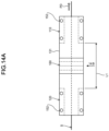
- a movable part 160 illustrated in Figs. 14A and 15 may be used.
- the movable part 160 is a stretchable portion constituting the connecting members 131 and 132 (only the connecting member 131 is illustrated in Figs. 12 and 13 ) that respectively connects the conductor members 110 and 120.
- the stretchable portion is formed of, for example, a flexible conductor such as a knitted wire.
- the stretchable portion constitutes a central portion of each of the connecting members 131 and 132 in the plate passing direction. Specifically, it connects plate portions 131A and 132A of the connecting members 131 and 132 connected to the conductor members 110 and 120.
- the stretchable portion is curved in a mountain shape toward the side opposite to the metal strip S side. As illustrated in Fig. 15 , the curved stretchable portion expands and contracts, so that the positions of the conductor members 110 and 120 in the plate passing direction move. When the positions of the conductor members 110 and 120 in the plate passing direction are changed, the movement of the conductor members 110 and 120 is simplified by disposing a roller or the like under the conductor members 110 and 120.
- the flexible conductor constituting the stretchable portion may be a water-cooled cable.
- a range D [mm] from an edge where 70% of an input power contributes to the temperature rise is represented, for example, as the following Formula (9) in relation to the induced current I.
- D ⁇ 15 ⁇ ln f + 107 mm
- the entire metal strip S in the width direction is heated only while passing under (or above) the conductor members 110 and 120 of the induction heating device 100.
- the heating range between the conductor members 110 and 120 is limited to the width-directional end portions SE of the metal strip S. This makes it possible to reduce the input power and avoid unnecessary influence on a metallographic structure. That is, in the present embodiment, the end portions SE of the metal strip S in the width direction can be efficiently heated, and the end cracking of the metal strip S at the time of cold rolling or the like can be prevented.
- the end cracking of the metal strip occurs, for example, in a pickling step or a cold rolling step after a hot rolling step. Therefore, the induction heating device 100 may be disposed, for example, at a preceding stage of a pickling device 500 in processing equipment including the pickling device 500 (see Fig. 20 ) for the metal strip S, or may be disposed at a preceding stage of a cold rolling device 510 in processing equipment including the cold rolling device 510 (see Fig. 21 ) for the metal strip S.
- the end cracking of the metal strip also occurs, for example, in a molten metal plating step.
- the induction heating device 100 may be disposed between a wiping device 522 and an alloying heating device 524 in processing equipment including, for example, a plating tank 520 in which a molten metal M (molten zinc as an example) illustrated in Fig. 22 is stored, the wiping device 522 that blows gas (for example, air) to the metal strip S to which the molten metal M is attached, and the alloying heating device 524 that raises the temperature of the molten metal M attached to the metal strip S to an alloying temperature by heating and holds the temperature to alloy the molten metal M.
- a molten metal M molten zinc as an example
- Fig. 4 is a plan view of an induction heating device for a metal strip according to a second embodiment of the disclosure.
- an induction heating device 200 according to the present embodiment is configured by a parallel circuit including conductor members 110A and 120A and connecting members 131A and 232A forming a primary closed circuit 101A, conductor members 110B and 120B and connecting members 131B and 232B forming a primary closed circuit 101B, and an AC power supply 240.
- the primary closed circuits 101A and 101B are disposed adjacent to each other in the plate passing direction (direction indicated by an arrow PD in Fig. 4 ) of the metal strip S.
- each of the primary closed circuits 101A and 101B the configurations of the conductor members 110A and 110B and the conductor members 120A and 120B are similar to those of the conductor members 110 and 120 in the first embodiment.
- the conductor member 120A constituting the primary closed circuit 101A and the conductor member 110B constituting the primary closed circuit 101B are disposed adjacent to each other in the plate passing direction of the metal strip S, and pass in-phase currents.
- the connecting members 131A and 131B connect the conductor members 110A and 120A and the conductor members 110B and 120B to each other at positions separated from the width-directional end portions SE of the metal strip S in plan view to form the primary closed circuits 101A and 101B, respectively.
- the connecting members 232A and 232B respectively connect the conductor members 110A and 120A and the conductor members 110B and 120B to each other at positions separated by a distance E from the width-directional end portions SE of the metal strip S to form the primary closed circuits 101A and 101B, and connect the primary closed circuits 101A and 101B in parallel to the AC power supply 240.
- the AC power supply 240 is connected to the primary closed circuits 101A and 101B so that the in-phase AC currents are passed to the conductor members adjacent to each other in the plate passing direction of the metal strip S, that is, the conductor member 120A and the conductor member 110B.
- the appropriate distance L can be set as the sum of the primary closed circuits 101A and 101B.
- an inductance of each primary closed circuit can be reduced to about half as compared with a case where the distance L is set with a single primary closed circuit.
- the inductance and the impedance can be reduced.
- the inductance L1 and the inductance L2 are substantially equal, the inductance is about half according to the above Formula (10).
- the parallelization makes it possible to reduce the inductance even when the required separation length is long, so that it is possible to solve the safety problem associated with the reduction of the power load and the increase in voltage.
- L is an inductance [H]
- C is a capacitor capacitance [F].
- the heating range of the width-directional end portions SE of the metal strip S can be narrowed, and the limited range of the width-directional end portions SE can be effectively heated.
- Fig. 5 is a plan view of an induction heating device for a metal strip according to another example of the second embodiment of the disclosure.
- connecting members 232C and 232D connect the primary closed circuits 101A and 101B in series to the AC power supply 240.
- in-phase AC currents are passed to the conductor member 120A and the conductor member 110B adjacent to each other in the plate passing direction of the metal strip S.
- magnitudes of the currents flowing through the primary closed circuits can be made the same.
- An oscillation condition can be changed by increasing the inductance.
- the series connection increases the inductance and decreases the frequency.
- ⁇ is a specific resistance [ ⁇ cm]
- ⁇ r is a relative permeability
- f is a frequency [Hz].
- the induction heating device 200 may manually switch between the series connection and the parallel connection of the primary closed circuits 101A and 101B, or may include a switching circuit that automatically switches between them.
- the switching circuit includes, for example, a switch that selectively connects the AC power supply 240 to any one of the connecting members 232A and 232B illustrated in Fig. 4 or the connecting members 232C and 232D illustrated in Fig. 5 .
- a switch 201A and a switch 201B illustrated in Figs. 18 and 19 may be used to switch between the parallel connection (connection in Fig. 18 ) and the series connection (connection in Fig. 19 ).
- a contact A of the switch 201A connected to the conductor member 120A and a contact B of the conductor member 110B are short-circuited.
- a contact D of the switch 201B connected to the connecting member 232A and a contact E connected to the connecting member 232B are short-circuited.
- the primary closed circuit 101A and the primary closed circuit 101B are connected in parallel.
- the contact A of the switch 201A connected to the conductor member 120A is released from the contact B of the conductor member 110B.
- the primary closed circuit 101A and the primary closed circuit 101B are connected in series by short-circuiting the contact D of the switch 201B connected to the connecting member 232A and the contact C connected to the conductor member 110B.
- Figs. 6A and 6B are cross-sectional views for explaining a third embodiment of the disclosure.
- magnetic cores 351, 352, 361, and 362 are disposed on the surfaces of the plate portions 111, 112, 121, and 122 constituting the conductor members on the sides opposite to the metal strip S.
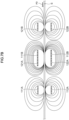
- the magnetic fluxes freely circulating on the side opposite to the metal strip S of the plate portions 111, 112, 121, and 122 constituting the conductor members pass through the magnetic cores 351, 352, 361, and 362 having high magnetic permeability in a concentrated manner as compared with the case where the magnetic cores are not disposed as illustrated in Fig.
- the magnetic fluxes generated by the currents flowing through the conductors can be concentrated on the plate portions 111, 112, 121, and 122 of the conductor members, so that the gap with the metal strip S can be increased, and for example, it can correspond to a waveform shape of the metal strip S in the thickness direction.
- the magnetic core only needs to secure an appropriate cross-sectional area that is not magnetically saturated.
- a ferrite core having a small cross-sectional area even when the saturation magnetic flux density is small may be used, and a ferromagnetic material such as a laminated electromagnetic steel plate or amorphous having a large saturation magnetic flux density may be used in the case of a relatively low frequency.
- a cooling device such as a water-cooled copper plate to cool the magnetic core.
- Figs. 7A and 7B are cross-sectional views for explaining another example of the third embodiment of the disclosure.
- Fig. 7B includes only plate portions 111A, 111B, 112A, 112B, 121A, 121B, 122A, and 122B constituting the conductor members, but in the case of Fig. 6B , which is a single closed circuit, the magnetic fluxes are freely radiated in a front-rear direction in the traveling direction (the same as the plate passing direction) of the metal strip S, so that the magnetic fluxes are less likely to concentrate.
- the magnetic fluxes generated in the plate portions 111A, 111B, 112A, and 112B cannot narrow the range in which it can fly in the front-rear direction in a longitudinal direction (the same as the plate passing direction) of the metal strip S due to the magnetic fluxes of the opposite phase generated in the plate portions 111A, 112A, 121B, and 122B, and the magnetic fluxes are confined in the vicinity of the plate portions 111A, 111B, 112A, and 112B, so that the induced currents can be efficiently concentrated.
- the magnetic cores 351, 352, 361, 362, 371, and 372 are disposed on the surface of the plate portions 111A, 111B, 112A, 112B, 121A, 121B, 122A, and 122B constituting the conductor members on the sides opposite to the metal strip S, the induced currents can be more efficiently concentrated.
- the magnetic cores 371 and 372 may be divided in the middle in the longitudinal direction and the width direction as long as they are close to each other, but it is desirable that they are disposed in common on each of the two plate portions 121A and 111B and the plate portions 122A and 122B of the conductor members adjacent to each other in the plate passing direction of the metal strip S. That is, the magnetic core 371 covers both the back sides of the plate portions 121A and 111B of the conductor member, and the magnetic core 372 covers both the back sides of the plate portions 122A and 112B of the conductor member.
- the magnetic fluxes easily enter the metal strip S as compared with the case where the magnetic cores are not disposed as illustrated in Fig. 7B .
- the metal strip S can be more effectively induction-heated.
- the gap between the conductor member and the metal strip S can be increased, and the leakage magnetic flux can be reduced similarly to the above example.
- Fig. 8A is a plan view of an induction heating device for a metal strip according to a fourth embodiment of the disclosure
- Fig. 9 is a side view of the induction heating device illustrated in Fig. 8A as viewed in a direction of an arrow 9-9.
- an induction heating device 400 according to the present embodiment includes conductor members 110 and 120 and connecting members 132 and 431 forming the primary closed circuit 101, and the AC power supply 140.
- the connecting members 431 and 132 are disposed on an upper surface or a lower surface on the end portion side of the metal strip S so as not to interfere with the metal strip S in the thickness direction of the metal strip S.
- the connecting members 431 and 132 are disposed on an upper surface or a lower surface on the end portion side of the metal strip S so as not to interfere with the metal strip S in the thickness direction of the metal strip S.
- the plate portions 111 and 121 of the conductor member on the front surface side of the metal strip S and the plate portion 112 and 122 of the conductor member on the back surface side are respectively connected by the connecting member 431, and the conductor members are not connected between the front surface side and the back surface side of the metal strip S.
- the fourth embodiment of the disclosure in addition to obtaining the effects similar to those of the first embodiment, even in a case where it is necessary to perform maintenance by removing the induction heating device 400 from the conveyance line of the metal strip S, even when the induction heating device is pulled out downward in the drawing (power supply side), it is not necessary to stop and cut the metal strip S being conveyed even during operation, and maintenance can be easily performed.
- the connecting members 131 and 132 are separated from the width-directional end portions SE of the metal strip S, but the disclosure is not limited to this configuration.
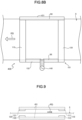
- the connecting members may overlap the width-directional end portions SE of the metal strip S in plan view (for example, the connecting members may overlap the width-directional end portions SE of the metal strip S by about several tens mm).
- the connecting members are disposed so as to partially overlap the width-directional end portions SE of the metal strip S in plan view with respect to the maximum plate width of a heated material that treats the connecting members above and below the conductor members 110 and 120. With such a configuration, it is possible to avoid contact between the connecting members and the width-directional end portions of the metal strip S.
- a width dimension of the connecting members may be a width dimension or more of the conductor members 110 and 120.
- the metal strip S which is a thin plate is used as the metal plate, but the disclosure is not limited thereto.
- a thick metal such as a thick plate or a slab may be used as the metal plate. Even in this case, the effects of the disclosure can be obtained similarly to the first embodiment.
- the heated material can also be applied in a stationary state.
- Fig. 17 illustrates a current flow on the side surface of the thick metal in a state where currents flow through the thick metal by the induction heating device of the disclosure (see Fig. 16 ).
- Figs. 10 and 11 are graphs illustrating analysis results for verifying the effects of heating the width-directional end portions of the metal strip in the embodiment of the disclosure.
- the induction heating device as described above with reference to Figs. 1 to 3 was subjected to electromagnetic field analysis by a finite element method under the following conditions to calculate a ratio between a temperature Tc at the width-directional center portion and a temperature Te at the width-directional end portion of the metal strip, and a temperature (edge temperature) at the width-directional end portion.
- a ratio L/B of the width B to the distance L of the conductor members is 1.
- the temperature Te at the width-directional end portion of the metal strip greatly exceeds the temperature Tc at the central portion.
- the edge temperature is low when the ratio L/B is in a range of 1 or more and 2 or less, but when the ratio L/B exceeds 2, the edge temperature exceeds 50°C, and the edge temperature increases as the ratio L/B increases.
- An induction heating device for a metal plate including:
- the induction heating device described in supplementary note 2 in which the first conductor member and the second conductor member are disposed at a front surface side and a back surface side of the metal plate, respectively.
- the induction heating device for a metal plate described in supplementary note 4 further including a switching circuit switchable between series connection and parallel connection of the first and second primary closed circuits.
- Processing equipment for a metal plate including:
- Processing equipment for a metal plate including:
- Processing equipment for a metal plate including:
- An induction heating method of a metal plate including:
- An induction heating device for a metal strip including:
- Processing equipment for a metal strip including:
- Processing equipment for a metal strip including:
- An induction heating method of a metal strip including:
- the entire metal strip in the width direction is heated only while passing under (or above) the conductor members, and a heating range between the conductor members is limited to the width-directional end portions of the metal strip.
- the end portions of the metal strip in the width direction can be efficiently heated, and the end cracking of the metal strip can be prevented. Since it is possible to ensure a relatively wide interval between an induction coil and a heated material, it is possible to easily cope with deformation, meandering, and the like of the heated material without additional equipment.
Landscapes
- Engineering & Computer Science (AREA)
- Mechanical Engineering (AREA)
- Chemical & Material Sciences (AREA)
- Physics & Mathematics (AREA)
- General Engineering & Computer Science (AREA)
- Thermal Sciences (AREA)
- Crystallography & Structural Chemistry (AREA)
- Materials Engineering (AREA)
- Metallurgy (AREA)
- Organic Chemistry (AREA)
- Power Engineering (AREA)
- Electromagnetism (AREA)
- Combustion & Propulsion (AREA)
- General Induction Heating (AREA)
Abstract
Description
- The present disclosure relates to an induction heating device for a metal plate, processing equipment for a metal plate, and an induction heating method of a metal plate.
- In cold rolling of a relatively hard steel material such as stainless steel or high tensile strength steel, since brittleness of the steel material is higher than usual, end cracking may occur at end portions in a width direction. For example, Japanese Patent Application Laid-Open (
JP-A) No. 2010-221224 JP-A No. 2010-221224 - In a case of a thick steel material such as a hot-rolled slab, the end portions of the steel material cool before being extracted from a heating furnace, subjected to rough rolling, and subjected to finish rolling. Therefore, in order to improve rolling dimensional accuracy and stabilize a quality of the hot-rolled material, a transverse-type induction heating device such as the C-shaped inductor as described above is usually provided before a finish rolling mill.
- In alloying of hot dip galvanizing and the like, for example, in order to prevent a decrease in an end portion temperature from resulting in poor alloying,
JP-A No. 2009-149970 -
JP-A No. 2010-221224 JP-A No. 2010-221224 - In a case where the end portions of the steel plate are heated by flame as in
JP-A No. 2009-149970 - Therefore, an object of the disclosure is to provide a technique for efficiently heating only a specific range of end portions of a metal plate in a width direction to increase a temperature of the end portions of the metal plate to stabilize a quality of the end portions even when a plate width of the metal plate is changed or the metal plate is conveyed in a meandering manner, and solving a problem caused by the temperature decrease of plate end portions such as prevention of end cracking of the metal plate, improvement of rolling dimensional accuracy, or avoidance of poor alloying.
- An aspect of the disclosure is an induction heating device for a metal plate, the induction heating device including: a first conductor member that faces at least one of a front surface or a back surface of the metal plate and that is disposed across the metal plate in a width direction; a second conductor member that is separated from the first conductor member by a first distance in a plate passing direction of the metal plate, that faces at least one of the front surface or the back surface of the metal plate, and that is disposed across the metal plate in the width direction; connecting members that connect the first conductor member and the second conductor member to each other at positions separated from width-directional end portions of the metal plate to form a primary closed circuit; and an AC power supply connected to the primary closed circuit, in which the first distance is larger than a sum of dimensions of the first conductor member and the second conductor member in the plate passing direction of the metal plate.
- Another aspect of the disclosure is an induction heating method of a metal plate, the induction heating method including: a step of passing an AC current to a primary closed circuit formed by a first conductor member that faces at least one of a front surface or a back surface of the metal plate and that is disposed across the metal plate in a width direction, a second conductor member that faces at least one of the front surface or the back surface of the metal plate, that is separated from the first conductor member by a first distance in a plate passing direction of the metal plate, and that is disposed across the metal plate in the width direction, and connecting members that connect the first conductor member and the second conductor member to each other at positions separated from width-directional end portions of the metal plate; and in the metal plate, a step of induction-heating the width-directional end portions of the metal plate by allowing a secondary closed circuit formed by induced currents generated in regions respectively facing the first conductor member and the second conductor member to pass through the width-directional end portions of the metal plate.
- According to the disclosure, it is possible to efficiently heat only a specific range of end portions of a metal plate in a width direction to increase an end portion temperature of the metal plate and stabilize a quality of the end portions even when a plate width of the metal plate is changed or the metal plate is conveyed in a meandering manner, and it is possible to solve a problem caused by a temperature decrease of plate end portions, such as prevention of end cracking of the metal plate, improvement of rolling dimensional accuracy, or avoidance of poor alloying.
-
-
Fig. 1 is a plan view of an induction heating device for a metal plate according to a first embodiment of the disclosure. -
Fig. 2A is a side view of the induction heating device illustrated inFig. 1 as viewed in a direction of anarrow 2A-2A. -
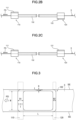
Fig. 2B is a side view (side view corresponding toFig. 2A ) illustrating a modification of the induction heating device illustrated inFig. 1 . -
Fig. 2C is a side view (side view corresponding toFig. 2A ) illustrating another modification of the induction heating device illustrated inFig. 1 . -
Fig. 3 is a view conceptually illustrating induced currents generated in a metal plate in the examples ofFigs. 1 and2A to 2C . -
Fig. 4 is a plan view of an induction heating device for a metal plate according to a second embodiment of the disclosure. -
Fig. 5 is a plan view of an induction heating device for a metal plate according to another example of the second embodiment of the disclosure. -
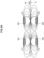
Fig. 6A is a cross-sectional view for explaining a third embodiment of the disclosure. -
Fig. 6B is a cross-sectional view for explaining the third embodiment of the disclosure. -
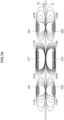
Fig. 7A is a cross-sectional view for explaining another example of the third embodiment of the disclosure. -
Fig. 7B is a cross-sectional view for explaining another example of the third embodiment of the disclosure. -
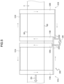
Fig. 8A is a plan view of an induction heating device for a metal plate (narrow) according to a fourth embodiment of the disclosure. -
Fig. 8B is a plan view of the induction heating device for a metal plate (wide) according to the fourth embodiment of the disclosure. -
Fig. 9 is a side view of the induction heating device illustrated inFig. 8A as viewed in a direction of an arrow 9-9. -
Fig. 10 is a graph illustrating an analysis result for verifying an effect of heating width-directional end portions of the metal plate in the embodiment of the disclosure. -
Fig. 11 is a graph illustrating an analysis result for verifying the effect of heating the width-directional end portions of the metal plate in the embodiment of the disclosure. -
Fig. 12 is a side view for explaining a movable part used in the embodiment of the disclosure. -
Fig. 13 is a side view illustrating a state in which a distance between conductor members is changed using the movable part inFig. 12 . -
Fig. 14A is a side view for explaining a modification of the movable part used in the embodiment of the disclosure. -
Fig. 14B is a view as viewed from a direction of anarrow 14B inFig. 14A . -
Fig. 15 is a side view illustrating a state in which a distance between conductor members is changed using the movable part inFig. 12 . -
Fig. 16 is a plan view of a state in which the induction heating device according to the embodiment of the disclosure is applied to a thick metal. -
Fig. 17 is a side view illustrating currents flowing through the width-directional end portions when the side surface of the thick metal illustrated inFig. 16 is viewed. -
Fig. 18 is a plan view of an induction heating device as still another example of the metal plate according to the second embodiment of the disclosure. -
Fig. 19 is a plan view illustrating a state in which a circuit of the induction heating device ofFig. 18 is switched. -
Fig. 20 is a schematic configuration view illustrating an example of processing equipment using the induction heating device for a metal plate according to the embodiment of the disclosure. -
Fig. 21 is a schematic configuration view illustrating another example of the processing equipment using the induction heating device for a metal plate according to the embodiment of the disclosure. -
Fig. 22 is a schematic configuration view illustrating another example of the processing equipment using the induction heating device for a metal plate according to the embodiment of the disclosure. - Hereinafter, an embodiment of the disclosure will be described in detail with reference to the accompanying drawings. In the present specification and the drawings, components having substantially the same functional configuration are denoted by the same reference numerals, and redundant description is omitted.
-
Fig. 1 is a plan view of an induction heating device for a metal plate according to a first embodiment of the disclosure, andFig. 2A is a side view of the induction heating device illustrated inFig. 1 as viewed in a direction of anarrow 2A-2A. As illustrated inFigs. 1 and2 , aninduction heating device 100 according to the present embodiment is a device that heats a metal strip S as a metal plate using electromagnetic induction. Here, the metal strip S used in the present embodiment is, for example, a belt-shaped thin plate, but the disclosure is not limited thereto. - The
induction heating device 100 of the present embodiment includesconductor members members AC power supply 140. Theconductor member 110 faces at least one of a front surface or a back surface of the metal strip S and is disposed across the metal strip S in the width direction. Similarly to theconductor member 110, theconductor member 120 faces at least one of the front surface or the back surface of the metal strip S and is disposed across the metal strip S in the width direction. Theconductor member 120 is separated from theconductor member 110 by a distance L in a plate passing direction (direction indicated by an arrow PD inFig. 1 ) of the metal strip S. Here, the distance L is a distance between inner sides of theconductor members conductor members - In the connecting
members conductor members closed circuit 101, and theAC power supply 140 is connected to the primaryclosed circuit 101. The connectingmembers members member 131 or the connectingmember 132. In this regard, when the distance E exceeds 12% of the maximum width Wmax, there are concerns about an increase in size of the device and an increase in an impedance of the primaryclosed circuit 101. - The
conductor members conductor members AC power supply 140 passing an AC current to the primaryclosed circuit 101 generates induced currents to be described later in the metal strip S. - Here, as illustrated in
Fig. 2A , theconductor members plate portions plate portions plate portions conductor member 110 are disposed to face the front surface and the back surface of the metal strip S, respectively, and theplate portions conductor member 120 are disposed to face the front surface and the back surface of the metal strip S, respectively. The disclosure is not limited thereto, and as in the example illustrated inFig. 2B , theplate portion 111 of theconductor member 110 may face the front surface of the metal strip S, and theplate portion 122 of theconductor member 120 may face the back surface of the metal strip S, or theplate portion 112 of theconductor member 110 may face the back surface of the metal strip S, and theplate portion 121 of theconductor member 120 may face the front surface of the metal strip S. As in the example illustrated inFig. 2C , both theplate portion 111 of theconductor member 110 and theplate portion 121 of theconductor member 120 may face only the front surface of the metal strip S, or both theplate portion 112 of theconductor member 110 and theplate portion 122 of theconductor member 120 may face only the back surface of the metal strip S. In other words, theconductor member 110 and theconductor member 120 are disposed to respectively face the same side surface of the metal strip S. - In the present embodiment, as illustrated in
Figs. 1 and 2A , theconductor members members closed circuit 101 constituted by the air-core coil is connected to theAC power supply 140. -
Fig. 3 is a view conceptually illustrating induced currents I generated in the metal strip S in the examples ofFigs. 1 and 2A . In the metal strip S, the secondaryclosed circuit 102 formed by the induced currents I generated in the regions respectively facing theconductor members induction heating device 100 flows in the width direction of the metal strip S in the regions respectively facing theconductor members closed circuit 102 circulate in the metal strip S. The induced currents I flowing through the secondaryclosed circuit 102 can suppress a calorific value because a current density is small at a central portion of the metal strip S, but the current density in a limited range from the end portion increases at the width-directional end portions SE due to a skin effect in which a high frequency current is concentrated at the end portions. As a result, the width-directional end portions SE of the metal strip S can be effectively heated. - As is clear from
Fig. 3 , in the disclosure, in the problem that a non-magnetic material cannot be heated due to a penetration depth of the current, which is a problem in a so-called LF heating method of heating a thin plate with a solenoid coil, the circulating currents do not overlap by shifting the conductors so as not to overlap each other in a traveling direction, and thus, it is possible to heat both a non-magnetic material and a magnetic material. - In addition, by separating the
conductor members conductor member 120 to when the width-directional end portions SE pass under (or above) theconductor member 110, so that a heating duration time is L/v. In this regard, at a width-directional center portion of the metal strip S, heating is performed only while passing under (or above) theconductor member 120 and while passing under (or above) theconductor member 110, so that the heating duration time is (B1 + B2)/v. Therefore, by satisfying L > B1 + B2, the heating duration time can be made longer in the width-directional end portions SE than in the width-directional center portion of the metal strip S. In this manner, a calorific value Qc of the width-directional center portion of the metal strip S and a calorific value Qe of the width-directional end portions SE can be adjusted by the distance L between theconductor members - More specifically, the calorific value Qc of the width-directional center portion of the metal strip S can be calculated by the following Formula (1) using a plate width W, a plate thickness t, a specific resistance ρ1 of a portion facing the
conductor member 110, and a specific resistance ρ2 of a portion facing theconductor member 120 of the metal strip S in addition to the above respective amounts.
[Mathematical Formula 1]
- In this regard, the calorific value Qe (sum of both sides) of the width-directional end portions SE of the metal strip S can be calculated by the following Formula (2) using a specific resistance ρe at the width-directional end portions SE of the metal strip S in addition to the above-described respective amounts.
[Mathematical Formula 2]
- A ratio between the calorific value Qc of the width-directional center portion and the calorific value Qe of the width-directional end portions SE of the metal strip S is expressed by the following Formula (3) from the above Formulas (1) and (2).
[Mathematical Formula 3]
- From the above Formula (3), the conditions for intensively heating the width-directional end portions SE while suppressing the temperature rise of the width-directional center portion of the metal strip S will be examined. When ρ1 = ρ2 = ρc in Formula (3), the following Formula (4) is obtained.
[Mathematical Formula 4]
- Here, the calorific values Qc and Qe are represented by the following Formulas (5) and (6) using a specific gravity γ of the metal strip S, specific heats Cpc and Cpe, temperature rise amounts ΔTc and ΔTe of each of the width-directional center portion and the width-directional end portions SE, and an average dimension B = (B1 + B2)/2 of the conductor members. When Formulas (5) and (6) are substituted into the Formula (4) and rearranged, Formulas (7) and (8) are obtained.

- In the above Formula (8), when B = 0.1 m and D = 0.07 m, and ΔTe of the width-directional end portions SE is set to 500°C while the temperature rise amount ΔTc of the width-directional center portion of the metal strip S is suppressed to 10°C, an appropriate distance L is obtained as follows by substituting the specific heats Cpc and Cpe and the specific resistances ρc and ρe corresponding to the respective temperature rise amounts. In order to set the appropriate distance L according to the conditions, the connecting
members induction heating device 100 may include a movable part capable of moving at least one of theconductor members movable parts 150 illustrated inFigs. 12 and13 may be used. Themovable parts 150 are a plurality of bolt holes provided in the connectingmembers 131 and 132 (only the connectingmember 131 is illustrated inFigs. 12 and13 ) that respectively connects theconductor members members conductor members conductor members bolts 152, a distance between theconductor members conductor members Fig. 12 to the positions illustrated inFig. 13 , the distance between theconductor members conductor members conductor members Fig. 12 ) or the like under theconductor members - As another example of the movable part of the disclosure, a
movable part 160 illustrated inFigs. 14A and15 may be used. Themovable part 160 is a stretchable portion constituting the connectingmembers 131 and 132 (only the connectingmember 131 is illustrated inFigs. 12 and13 ) that respectively connects theconductor members Fig. 15 , the stretchable portion constitutes a central portion of each of the connectingmembers plate portions 131A and 132A of the connectingmembers conductor members Fig. 14B , the stretchable portion is curved in a mountain shape toward the side opposite to the metal strip S side. As illustrated inFig. 15 , the curved stretchable portion expands and contracts, so that the positions of theconductor members conductor members conductor members conductor members 
- With respect to the frequency f [kHz] of the AC current, according to the results of the analysis performed by the present discloser, a range D [mm] from an edge where 70% of an input power contributes to the temperature rise is represented, for example, as the following Formula (9) in relation to the induced current I.
[Mathematical Formula 7]
- According to the configuration of the first embodiment of the disclosure as described above, the entire metal strip S in the width direction is heated only while passing under (or above) the
conductor members induction heating device 100. The heating range between theconductor members conductor members - Here, the end cracking of the metal strip occurs, for example, in a pickling step or a cold rolling step after a hot rolling step. Therefore, the
induction heating device 100 may be disposed, for example, at a preceding stage of apickling device 500 in processing equipment including the pickling device 500 (seeFig. 20 ) for the metal strip S, or may be disposed at a preceding stage of acold rolling device 510 in processing equipment including the cold rolling device 510 (seeFig. 21 ) for the metal strip S. The end cracking of the metal strip also occurs, for example, in a molten metal plating step. Therefore, theinduction heating device 100 may be disposed between a wipingdevice 522 and an alloyingheating device 524 in processing equipment including, for example, aplating tank 520 in which a molten metal M (molten zinc as an example) illustrated inFig. 22 is stored, thewiping device 522 that blows gas (for example, air) to the metal strip S to which the molten metal M is attached, and the alloyingheating device 524 that raises the temperature of the molten metal M attached to the metal strip S to an alloying temperature by heating and holds the temperature to alloy the molten metal M. -
Fig. 4 is a plan view of an induction heating device for a metal strip according to a second embodiment of the disclosure. As illustrated, aninduction heating device 200 according to the present embodiment is configured by a parallel circuit includingconductor members members closed circuit 101A,conductor members members closed circuit 101B, and anAC power supply 240. The primaryclosed circuits Fig. 4 ) of the metal strip S. In each of the primaryclosed circuits conductor members conductor members conductor members conductor member 120A constituting the primaryclosed circuit 101A and theconductor member 110B constituting the primaryclosed circuit 101B are disposed adjacent to each other in the plate passing direction of the metal strip S, and pass in-phase currents. - The connecting
members conductor members conductor members closed circuits members conductor members conductor members closed circuits closed circuits AC power supply 240. TheAC power supply 240 is connected to the primaryclosed circuits conductor member 120A and theconductor member 110B. - According to the configuration of the second embodiment of the disclosure as described above, in addition to obtaining the same effects as those of the first embodiment, the appropriate distance L can be set as the sum of the primary
closed circuits closed circuits conductor member 120A and theconductor member 110B adjacent to each other, the magnetic fluxes generated around the conductor members are in the same direction, and the magnetic fluxes are likely to concentrate on the metal strip S. - Specifically, when the primary
closed circuit 101A (inductance L1, impedance Z1) configured by one set ofconductor members closed circuit 101B (inductance L2, impedance Z2) configured by another set ofconductor members 
- In general, when the parallel connection is made, the inductance and the impedance can be reduced. When the inductance L1 and the inductance L2 are substantially equal, the inductance is about half according to the above Formula (10).
- In particular, when the plate passing speed of the metal strip S (usually a thin material) is high and a sufficient heating time cannot be taken, a separation distance of a set of conductor members to be installed becomes long, the inductance and the impedance become large, a burden of the power supply becomes large such as increase in voltage, and equipment cost increases and a safety problem occurs.
- The parallelization makes it possible to reduce the inductance even when the required separation length is long, so that it is possible to solve the safety problem associated with the reduction of the power load and the increase in voltage.
- Even in a case where large electric power is input without increasing the separation distance, the current is shunted, so that heat generation of one set of conductor members can be reduced and efficiency can be increased.
- As indicated below, a resonance frequency f of the current is increased.
[Mathematical Formula 8]
- L is an inductance [H], and C is a capacitor capacitance [F].
- When the resonance frequency increases, the heating range of the width-directional end portions SE of the metal strip S can be narrowed, and the limited range of the width-directional end portions SE can be effectively heated.
-
Fig. 5 is a plan view of an induction heating device for a metal strip according to another example of the second embodiment of the disclosure. As a difference from the above example, in the illustrated example, connectingmembers closed circuits AC power supply 240. The same applies in that in-phase AC currents are passed to theconductor member 120A and theconductor member 110B adjacent to each other in the plate passing direction of the metal strip S. By connecting the primaryclosed circuits - Specifically, when the series connection is made, a combined inductance L is expressed by the following Formula.

- The series connection increases the inductance and decreases the frequency.
- When the frequency is lowered, a penetration depth δ of the current can be deepened. Therefore, particularly in a case of a material having a large plate thickness, a heating range in a thickness direction can be widened, and a heating range from the width-directional end portions SE of the metal strip S can also be widened.
[Mathematical Formula 9]
- ρ is a specific resistance [µΩcm], µr is a relative permeability, and f is a frequency [Hz].
- Since all the currents flowing through the conductor members are the same, an amount of edge heating for each closed circuit can be the same even when the impedances are different.
- As described above, when the parallel/series connection can be freely performed, there is an advantage that the frequency, the current/power distribution, and the heating range of the width-directional end portions of the metal strip, which are appropriately required according to the load, can be relatively freely changed and a plurality of individual equipment need not be prepared.
- In general, in a case where a plate thickness is thin, a plate passing speed is fast, and a temperature change of a specific resistance is small (SUS304 or the like), since the change in the impedance is small and the power/current amount is large before and after the heating, parallel connection capable of reducing the heat generation of the conductor is desirable. In a case where there is an impedance difference before and after the heating, such as ordinary steel having a large temperature change of the specific resistance, or in a case of a thick steel material having a low plate passing speed, series connection in which the current amount between the circuits is the same, the inductance is large, and heating on the low frequency side is easy is desirable.
- The
induction heating device 200 may manually switch between the series connection and the parallel connection of the primaryclosed circuits AC power supply 240 to any one of the connectingmembers Fig. 4 or the connectingmembers Fig. 5 . As an example, a switch 201A and a switch 201B illustrated inFigs. 18 and19 may be used to switch between the parallel connection (connection inFig. 18 ) and the series connection (connection inFig. 19 ). InFig. 18 , a contact A of the switch 201A connected to theconductor member 120A and a contact B of theconductor member 110B are short-circuited. A contact D of the switch 201B connected to the connectingmember 232A and a contact E connected to the connectingmember 232B are short-circuited. As a result, the primaryclosed circuit 101A and the primaryclosed circuit 101B are connected in parallel. In this regard, inFig. 19 , the contact A of the switch 201A connected to theconductor member 120A is released from the contact B of theconductor member 110B. Then, the primaryclosed circuit 101A and the primaryclosed circuit 101B are connected in series by short-circuiting the contact D of the switch 201B connected to the connectingmember 232A and the contact C connected to theconductor member 110B. -
Figs. 6A and6B are cross-sectional views for explaining a third embodiment of the disclosure. As illustrated inFig. 6A , in the present embodiment,magnetic cores plate portions plate portions magnetic cores Fig. 6B , so that the magnetic fluxes concentrate and easily enter the metal strip S immediately below theconductor members plate portions - The magnetic core only needs to secure an appropriate cross-sectional area that is not magnetically saturated. For example, in the case of using a high frequency, a ferrite core having a small cross-sectional area even when the saturation magnetic flux density is small may be used, and a ferromagnetic material such as a laminated electromagnetic steel plate or amorphous having a large saturation magnetic flux density may be used in the case of a relatively low frequency. When heat generation is concerned, it is desirable to appropriately provide a cooling device such as a water-cooled copper plate to cool the magnetic core.
-
Figs. 7A and7B are cross-sectional views for explaining another example of the third embodiment of the disclosure.Fig. 7B includesonly plate portions Fig. 6B , which is a single closed circuit, the magnetic fluxes are freely radiated in a front-rear direction in the traveling direction (the same as the plate passing direction) of the metal strip S, so that the magnetic fluxes are less likely to concentrate. On the other hand, in another example of the third embodiment, in a case where in-phase currents are caused to flow through theplate portions plate portions plate portions plate portions Fig. 7A , in the present embodiment, when themagnetic cores plate portions magnetic cores plate portions plate portions magnetic core 371 covers both the back sides of theplate portions magnetic core 372 covers both the back sides of theplate portions Figs. 4 and5 , the magnetic fluxes easily enter the metal strip S as compared with the case where the magnetic cores are not disposed as illustrated inFig. 7B . As a result, the metal strip S can be more effectively induction-heated. The gap between the conductor member and the metal strip S can be increased, and the leakage magnetic flux can be reduced similarly to the above example. -
Fig. 8A is a plan view of an induction heating device for a metal strip according to a fourth embodiment of the disclosure, andFig. 9 is a side view of the induction heating device illustrated inFig. 8A as viewed in a direction of an arrow 9-9. As illustrated, aninduction heating device 400 according to the present embodiment includesconductor members members closed circuit 101, and theAC power supply 140. As a difference from the first embodiment, in the present embodiment, the connectingmembers Fig. 9 , theplate portions plate portion member 431, and the conductor members are not connected between the front surface side and the back surface side of the metal strip S. - According to the fourth embodiment of the disclosure as described above, in addition to obtaining the effects similar to those of the first embodiment, even in a case where it is necessary to perform maintenance by removing the
induction heating device 400 from the conveyance line of the metal strip S, even when the induction heating device is pulled out downward in the drawing (power supply side), it is not necessary to stop and cut the metal strip S being conveyed even during operation, and maintenance can be easily performed. - In the above-described embodiment, the connecting
members Fig. 8B , the connecting members may overlap the width-directional end portions SE of the metal strip S in plan view (for example, the connecting members may overlap the width-directional end portions SE of the metal strip S by about several tens mm). Specifically, the connecting members are disposed so as to partially overlap the width-directional end portions SE of the metal strip S in plan view with respect to the maximum plate width of a heated material that treats the connecting members above and below theconductor members conductor members - In the above embodiment, the metal strip S which is a thin plate is used as the metal plate, but the disclosure is not limited thereto. A thick metal such as a thick plate or a slab may be used as the metal plate. Even in this case, the effects of the disclosure can be obtained similarly to the first embodiment. Although the case where the heated material is moving has been exemplified, the heated material can also be applied in a stationary state.
Fig. 17 illustrates a current flow on the side surface of the thick metal in a state where currents flow through the thick metal by the induction heating device of the disclosure (seeFig. 16 ). -
Figs. 10 and11 are graphs illustrating analysis results for verifying the effects of heating the width-directional end portions of the metal strip in the embodiment of the disclosure. The induction heating device as described above with reference toFigs. 1 to 3 was subjected to electromagnetic field analysis by a finite element method under the following conditions to calculate a ratio between a temperature Tc at the width-directional center portion and a temperature Te at the width-directional end portion of the metal strip, and a temperature (edge temperature) at the width-directional end portion. - · Plate width W of metal strip = 1200 mm
- · Thickness t of metal strip = 2 mm
- · Width B of conductor member = 200 mm
- · Frequency f of AC current = 10 kHz
- · Magnitude of AC current = 10 kA
- · Distance L between conductor members = variable between 200 mm and 600 mm
- · Temperature T0 of the metal strip before heating = 0°C
- In the above analysis, when the distance L between the conductor members is minimized (100 mm), a ratio L/B of the width B to the distance L of the conductor members is 1. As illustrated in the graph of
Fig. 10 , when the ratio L/B is in a range of 1 or more, the temperature Te at the width-directional end portion of the metal strip greatly exceeds the temperature Tc at the central portion. In this regard, as illustrated in the graph ofFig. 11 , the edge temperature is low when the ratio L/B is in a range of 1 or more and 2 or less, but when the ratio L/B exceeds 2, the edge temperature exceeds 50°C, and the edge temperature increases as the ratio L/B increases. The fact that the ratio L/B exceeds 2 (L/B > 2) is equivalent to the fact that the distance L exceeds a total width of the two conductor members (L > 2B). Under such conditions, the induction heating device can efficiently heat the end portions of the metal strip in the width direction. - The preferred embodiments of the disclosure have been described in detail above with reference to the accompanying drawings, but the disclosure is not limited to these examples. It is obvious that a person skilled in the art to which the disclosure belongs can conceive various changes or modifications within the scope of the technical idea described in the claims, and it is naturally understood that these also belong to the technical scope of the disclosure.
- With regard to the above embodiments, the following supplementary notes are further disclosed.
- An induction heating device for a metal plate, the induction heating device including:
- a first conductor member that faces at least one of a front surface or a back surface of the metal plate and that is disposed across the metal plate in a width direction;
- a second conductor member that is separated from the first conductor member by a first distance in a plate passing direction of the metal plate, that faces at least one of the front surface or the back surface of the metal plate, and that is disposed across the metal plate in the width direction;
- connecting members that connect the first conductor member and the second conductor member to each other to form a primary closed circuit; and
- an AC power supply connected to the primary closed circuit, wherein
- the first distance is larger than a sum of dimensions of the first conductor member and the second conductor member in the plate passing direction of the metal plate.
- The induction heating device described in
supplementary note 1, in which the first conductor member and the second conductor member are disposed to face a same side surface of the metal plate. - The induction heating device described in
supplementary note 2, in which the first conductor member and the second conductor member are disposed at a front surface side and a back surface side of the metal plate, respectively. - The induction heating device for a metal plate described in any one of
supplementary notes 1 to 3, in which - first and second primary closed circuits each formed by the first conductor member, the second conductor member, and the connecting members are disposed adjacent to each other in the plate passing direction of the metal plate, and
- the AC power supply passes in-phase AC currents to conductor members adjacent to each other in the plate passing direction of the metal plate in the first and second primary closed circuits.
- The induction heating device for a metal plate described in
supplementary note 4, further including a switching circuit switchable between series connection and parallel connection of the first and second primary closed circuits. - The induction heating device for a metal plate described in any one of
supplementary notes 1 to 5, further including a magnetic core disposed on a surface of at least one conductor member of the first conductor member or the second conductor member on a side opposite to the metal plate. - The induction heating device for a metal plate described in any one of
supplementary notes 1 to 6, in which the connecting members are disposed on at least one side of the metal plate in the width direction so as not to interfere with the metal plate in a thickness direction of the metal plate. - The induction heating device for a metal plate described in any one of
supplementary notes 1 to 7, in which the connecting members includes a movable part capable of moving at least one conductor member of the first conductor member or the second conductor member in the plate passing direction of the metal plate. - Processing equipment for a metal plate, the processing equipment including:
- a pickling device for the metal plate; and
- the induction heating device for a metal plate described in any one of
supplementary notes 1 to 8, the induction heating device being disposed at a preceding stage of the pickling device. - Processing equipment for a metal plate, the processing equipment including:
- a cold rolling device for the metal plate; and
- the induction heating device for a metal plate described in any one of
supplementary notes 1 to 8, the induction heating device being disposed at a preceding stage of the cold rolling device. - Processing equipment for a metal plate, the processing equipment including:
- a wiping device that blows a gas to a metal plate to which a molten metal is attached;
- an alloying heating device that alloys, by heating, the molten metal attached to the metal plate; and
- the induction heating device for a metal plate described in any one of
supplementary notes 1 to 8, the induction heating device being disposed between the wiping device and the alloying heating device. - An induction heating method of a metal plate, the induction heating method including:
- a step of passing an AC current to a primary closed circuit formed by a first conductor member that faces at least one of a front surface or a back surface of the metal plate and that is disposed across the metal plate in a width direction, a second conductor member that faces at least one of the front surface or the back surface of the metal plate, that is separated from the first conductor member by a first distance in a plate passing direction of the metal plate, and that is disposed across the metal plate in the width direction, and connecting members that connect the first conductor member and the second conductor member to each other; and
- in the metal plate, a step of induction-heating width-directional end portions of the metal plate by allowing a secondary closed circuit formed by induced currents generated in regions respectively facing the first conductor member and the second conductor member to pass through the width-directional end portions of the metal plate.
- An induction heating device for a metal strip, the induction heating device including:
- a first conductor member that faces a front surface or a back surface of the metal strip and is disposed across the metal strip in a width direction;
- a second conductor member that is positioned to be separated from the first conductor member by a first distance in a plate passing direction of the metal strip, faces the front surface or the back surface of the metal strip, and is disposed across the metal strip in the width direction;
- connecting members that connect the first conductor member and the second conductor member to each other at positions separated from width-directional end portions of the metal strip to form a primary closed circuit; and
- an AC power supply connected to the primary closed circuit, wherein
- the first distance is larger than a sum of dimensions of the first conductor member and the second conductor member in the plate passing direction of the metal strip.
- The induction heating device for a metal strip described in supplementary note 13, in which
- first and second primary closed circuits each formed by the first conductor member, the second conductor member, and the connecting member are disposed adjacent to each other in the plate passing direction of the metal strip, and
- the AC power supply passes in-phase AC currents to conductor members adjacent to each other in the plate passing direction of the metal strip in the first and second primary closed circuits.
- The induction heating device for a metal strip described in supplementary note 14, further including a switching circuit switchable between series connection and parallel connection of the first and second primary closed circuits.
- The induction heating device for a metal strip described in any one of supplementary notes 13 to 15, further including a magnetic core disposed on a surface of at least one of the first conductor member or the second conductor member on a side opposite to the metal strip.
- The induction heating device for a metal strip described in any one of supplementary notes 13 to 16, in which the connecting members are disposed on at least one side of the metal strip in the width direction so as not to interfere with the metal strip in the thickness direction of the metal strip.
- The induction heating device for a metal strip described in any one of supplementary notes 13 to 17, in which the connecting members includes a movable part capable of moving at least one of the first conductor member or the second conductor member in the plate passing direction of the metal strip.
- Processing equipment for a metal strip, the processing equipment including:
- a pickling device for a metal strip; and
- the induction heating device for a metal strip described in any one of supplementary notes 13 to 18, the induction heating device being disposed at a preceding stage of the pickling device.
- Processing equipment for a metal strip, the processing equipment including:
- a cold rolling device for a metal strip; and
- the induction heating device for a metal strip described in any one of supplementary notes 13 to 18, the induction heating device being disposed at a preceding stage of the cold rolling device.
- An induction heating method of a metal strip, the induction heating method including:
- a step of passing an AC current to a primary closed circuit formed by a first conductor member that faces a front surface or a back surface of the metal strip and is disposed across the metal strip in a width direction, a second conductor member that faces the front surface or the back surface of the metal strip, is separated from the first conductor member by a first distance in a plate passing direction of the metal strip, and is disposed across the metal strip in the width direction, and connecting members that connect the first conductor member and the second conductor member to each other at positions separated from width-directional end portions of the metal strip; and
- in the metal strip, a step of induction-heating the width-directional end portions of the metal strip by allowing a secondary closed circuit formed by induced currents generated in regions respectively facing the first conductor member and the second conductor member to pass through the width-directional end portions of the metal strip.
- According to the above configuration, the entire metal strip in the width direction is heated only while passing under (or above) the conductor members, and a heating range between the conductor members is limited to the width-directional end portions of the metal strip. As a result, the end portions of the metal strip in the width direction can be efficiently heated, and the end cracking of the metal strip can be prevented. Since it is possible to ensure a relatively wide interval between an induction coil and a heated material, it is possible to easily cope with deformation, meandering, and the like of the heated material without additional equipment.
-
- 100, 200, 400 Induction heating device
- 101, 101A, 101B Primary closed circuit
- 102 Secondary closed circuit
- 110, 110A, 110B, 120, 120A, 120B Conductor member
- 131, 131A, 131B, 132, 232A, 232B, 232C, 232D, 431 Connecting member
- 140, 240 AC power supply
- 351, 352, 361, 362, 371, 372 Magnetic core
-
Pickling device 500 -
Cold rolling device 510 - Wiping
device 522 -
Alloying heating device 524 - S Metal strip
Claims (12)
- An induction heating device for a metal plate, the induction heating device comprising:a first conductor member that faces at least one of a front surface or a back surface of the metal plate and that is disposed across the metal plate in a width direction;a second conductor member that is separated from the first conductor member by a first distance in a plate passing direction of the metal plate, that faces at least one of the front surface or the back surface of the metal plate, and that is disposed across the metal plate in the width direction;connecting members that connect the first conductor member and the second conductor member to each other at positions separated from width-directional end portions of the metal plate to form a primary closed circuit; andan AC power supply connected to the primary closed circuit, wherein:
the first distance is larger than a sum of dimensions of the first conductor member and the second conductor member in the plate passing direction of the metal plate. - The induction heating device according to claim 1, wherein the first conductor member and the second conductor member are disposed to face a same side surface of the metal plate.
- The induction heating device according to claim 2, wherein the first conductor member and the second conductor member are disposed at a front surface side and a back surface side of the metal plate, respectively.
- The induction heating device for a metal plate according to any one of claims 1 to 3, wherein:first and second primary closed circuits each formed by the first conductor member, the second conductor member, and the connecting members are disposed adjacent to each other in the plate passing direction of the metal plate, andthe AC power supply passes in-phase AC currents to conductor members adjacent to each other in the plate passing direction of the metal plate in the first and second primary closed circuits.
- The induction heating device for a metal plate according to claim 4, further comprising a switching circuit switchable between series connection and parallel connection of the first and second primary closed circuits.
- The induction heating device for a metal plate according to any one of claims 1 to 5, further comprising a magnetic core disposed on a surface of at least one conductor member of the first conductor member or the second conductor member, on a side opposite to the metal plate.
- The induction heating device for a metal plate according to any one of claims 1 to 6, wherein the connecting members are disposed on at least one side of the metal plate in the width direction so as not to interfere with the metal plate in a thickness direction of the metal plate.
- The induction heating device for a metal plate according to any one of claims 1 to 7, wherein the connecting members includes a movable part capable of moving at least one conductor member of the first conductor member or the second conductor member in the plate passing direction of the metal plate.
- Processing equipment for a metal plate, the processing equipment comprising:a pickling device for the metal plate; andthe induction heating device for a metal plate according to any one of claims 1 to 8, the induction heating device being disposed at a preceding stage of the pickling device.
- Processing equipment for a metal plate, the processing equipment comprising:a cold rolling device for the metal plate; andthe induction heating device for a metal plate according to any one of claims 1 to 8, the induction heating device being disposed at a preceding stage of the cold rolling device.
- Processing equipment for a metal plate, the processing equipment comprising:a wiping device that blows a gas to a metal plate to which a molten metal is attached;an alloying heating device that alloys, by heating, the molten metal attached to the metal plate; andthe induction heating device for a metal plate according to any one of claims 1 to 8, the induction heating device being disposed between the wiping device and the alloying heating device.
- An induction heating method of a metal plate, the induction heating method comprising: a step of passing an AC current to a primary closed circuit formed by a first conductor member that faces at least one of a front surface or a back surface of the metal plate and that is disposed across the metal plate in a width direction, a second conductor member that faces at least one of the front surface or the back surface of the metal plate, that is separated from the first conductor member by a first distance in a plate passing direction of the metal plate, and that is disposed across the metal plate in the width direction, and connecting members that connect the first conductor member and the second conductor member to each other at positions separated from width-directional end portions of the metal plate; and in the metal plate, a step of induction-heating the width-directional end portions of the metal plate by allowing a secondary closed circuit formed by induced currents generated in regions respectively facing the first conductor member and the second conductor member to pass through the width-directional end portions of the metal plate.
Applications Claiming Priority (1)
| Application Number | Priority Date | Filing Date | Title |
|---|---|---|---|
| PCT/JP2022/029400 WO2024024117A1 (en) | 2022-07-29 | 2022-07-29 | Induction heating device for metal sheet, processing equipment for metal sheet, and induction heating method for metal sheet |
Publications (2)
| Publication Number | Publication Date |
|---|---|
| EP4563256A1 true EP4563256A1 (en) | 2025-06-04 |
| EP4563256A4 EP4563256A4 (en) | 2025-10-08 |
Family
ID=89705945
Family Applications (1)
| Application Number | Title | Priority Date | Filing Date |
|---|---|---|---|
| EP22953205.6A Pending EP4563256A4 (en) | 2022-07-29 | 2022-07-29 | Induction heating device for sheet metal, processing equipment for sheet metal and induction heating process for sheet metal |
Country Status (6)
| Country | Link |
|---|---|
| US (1) | US20260016227A1 (en) |
| EP (1) | EP4563256A4 (en) |
| JP (1) | JPWO2024024117A1 (en) |
| KR (1) | KR20250024076A (en) |
| CN (1) | CN119585058A (en) |
| WO (1) | WO2024024117A1 (en) |
Family Cites Families (10)
| Publication number | Priority date | Publication date | Assignee | Title |
|---|---|---|---|---|
| JPH0616470Y2 (en) * | 1987-05-11 | 1994-04-27 | 株式会社明電舎 | Flat plate induction heating coil device |
| JP2982601B2 (en) * | 1993-12-28 | 1999-11-29 | 日本鋼管株式会社 | High speed pickling apparatus and method for thin steel plate |
| JP2964911B2 (en) * | 1995-04-21 | 1999-10-18 | 住友金属工業株式会社 | Alloying hot-dip galvanizing method for P-added high-strength steel |
| JP4115904B2 (en) * | 2003-08-01 | 2008-07-09 | 菊池プレス工業株式会社 | Induction heating apparatus and induction heating method for thin plate article |
| JP2006310144A (en) * | 2005-04-28 | 2006-11-09 | Shimada Phys & Chem Ind Co Ltd | Induction heating apparatus and method for suppressing heating by high-frequency current leakage magnetic flux |
| KR100931167B1 (en) | 2006-12-26 | 2009-12-11 | 주식회사 포스코 | Apparatus for instantaneous rapid heating and alloying of both edges of hot-dip steel sheet |
| JP5391762B2 (en) * | 2009-03-19 | 2014-01-15 | Jfeスチール株式会社 | Induction heating method for steel plate edge |
| WO2016035893A1 (en) * | 2014-09-05 | 2016-03-10 | 新日鐵住金株式会社 | Induction heating device for metal strip |
| EP3439430B1 (en) * | 2016-03-30 | 2023-08-23 | Nippon Steel Corporation | Induction heating device and induction heating method |
| CN110300633B (en) * | 2017-02-28 | 2020-12-29 | 杰富意钢铁株式会社 | Cold rolling mill and cold rolling method |
-
2022
- 2022-07-29 EP EP22953205.6A patent/EP4563256A4/en active Pending
- 2022-07-29 WO PCT/JP2022/029400 patent/WO2024024117A1/en not_active Ceased
- 2022-07-29 CN CN202280098471.3A patent/CN119585058A/en active Pending
- 2022-07-29 KR KR1020257001442A patent/KR20250024076A/en active Pending
- 2022-07-29 US US18/995,162 patent/US20260016227A1/en active Pending
- 2022-07-29 JP JP2024536757A patent/JPWO2024024117A1/ja active Pending
Also Published As
| Publication number | Publication date |
|---|---|
| JPWO2024024117A1 (en) | 2024-02-01 |
| US20260016227A1 (en) | 2026-01-15 |
| CN119585058A (en) | 2025-03-07 |
| WO2024024117A1 (en) | 2024-02-01 |
| EP4563256A4 (en) | 2025-10-08 |
| KR20250024076A (en) | 2025-02-18 |
Similar Documents
| Publication | Publication Date | Title |
|---|---|---|
| US6248984B1 (en) | Method and apparatus for joining metal pieces | |
| JP5909562B2 (en) | Heating apparatus and heating method | |
| CA2683538C (en) | Induction heating system and induction heating method of metal plate | |
| US7087869B2 (en) | Transverse induction heating apparatus | |
| EP4563256A1 (en) | Induction heating device for metal sheet, processing equipment for metal sheet, and induction heating method for metal sheet | |
| US6285015B1 (en) | Induction heater with a unit for preventing generation of sparks | |
| TWI827179B (en) | Induction heating device of metal sheet, metal sheet processing equipment, and induction heating method of metal sheet | |
| JP6812999B2 (en) | Induction heating device for metal strips, manufacturing method for metal strips, and manufacturing method for alloyed hot-dip galvanized steel sheets | |
| KR101940887B1 (en) | Induction-heating apparatus | |
| JP2002043042A (en) | Single turn induction heating coil | |
| JP3482342B2 (en) | Induction heating device on the side of metal plate | |
| JP3236422B2 (en) | Continuous casting method of steel using magnetic field | |
| JP2995141B2 (en) | Induction heating device for metal plate | |
| JPH0616471Y2 (en) | Induction heating device | |
| JP6790660B2 (en) | Alloying method of hot-dip galvanized layer | |
| JP5815116B2 (en) | Stationary induction equipment | |
| JP6763261B2 (en) | Continuous hot-dip galvanized steel sheet and manufacturing method of alloyed hot-dip galvanized steel sheet | |
| JPWO2024024117A5 (en) | ||
| JP4369332B2 (en) | Transverse induction heating apparatus and transverse induction heating system | |
| RU2025103285A (en) | INDUCTION HEATING DEVICE FOR METAL PLATE, PROCESSING EQUIPMENT FOR METAL PLATE AND INDUCTION HEATING METHOD FOR METAL PLATE | |
| JPH1092561A (en) | Induction heating device | |
| JP2006093029A (en) | Induction heating device |
Legal Events
| Date | Code | Title | Description |
|---|---|---|---|
| STAA | Information on the status of an ep patent application or granted ep patent |
Free format text: STATUS: THE INTERNATIONAL PUBLICATION HAS BEEN MADE |
|
| PUAI | Public reference made under article 153(3) epc to a published international application that has entered the european phase |
Free format text: ORIGINAL CODE: 0009012 |
|
| STAA | Information on the status of an ep patent application or granted ep patent |
Free format text: STATUS: REQUEST FOR EXAMINATION WAS MADE |
|
| 17P | Request for examination filed |
Effective date: 20250215 |
|
| AK | Designated contracting states |
Kind code of ref document: A1 Designated state(s): AL AT BE BG CH CY CZ DE DK EE ES FI FR GB GR HR HU IE IS IT LI LT LU LV MC MK MT NL NO PL PT RO RS SE SI SK SM TR |
|
| A4 | Supplementary search report drawn up and despatched |
Effective date: 20250904 |
|
| RIC1 | Information provided on ipc code assigned before grant |
Ipc: B21B 45/00 20060101AFI20250829BHEP Ipc: H05B 6/10 20060101ALI20250829BHEP Ipc: F27B 9/06 20060101ALI20250829BHEP Ipc: F27D 11/06 20060101ALI20250829BHEP Ipc: B21B 45/06 20060101ALI20250829BHEP Ipc: C21D 1/10 20060101ALI20250829BHEP Ipc: C21D 1/42 20060101ALI20250829BHEP Ipc: C21D 9/46 20060101ALI20250829BHEP Ipc: C21D 9/60 20060101ALI20250829BHEP |
|
| DAV | Request for validation of the european patent (deleted) | ||
| DAX | Request for extension of the european patent (deleted) | ||
| STAA | Information on the status of an ep patent application or granted ep patent |
Free format text: STATUS: EXAMINATION IS IN PROGRESS |