EP4560268A1 - Resolver - Google Patents
Resolver Download PDFInfo
- Publication number
- EP4560268A1 EP4560268A1 EP23211749.9A EP23211749A EP4560268A1 EP 4560268 A1 EP4560268 A1 EP 4560268A1 EP 23211749 A EP23211749 A EP 23211749A EP 4560268 A1 EP4560268 A1 EP 4560268A1
- Authority
- EP
- European Patent Office
- Prior art keywords
- resolver
- hub
- housing
- windings
- elements
- Prior art date
- Legal status (The legal status is an assumption and is not a legal conclusion. Google has not performed a legal analysis and makes no representation as to the accuracy of the status listed.)
- Granted
Links
Images
Classifications
-
- G—PHYSICS
- G01—MEASURING; TESTING
- G01D—MEASURING NOT SPECIALLY ADAPTED FOR A SPECIFIC VARIABLE; ARRANGEMENTS FOR MEASURING TWO OR MORE VARIABLES NOT COVERED IN A SINGLE OTHER SUBCLASS; TARIFF METERING APPARATUS; MEASURING OR TESTING NOT OTHERWISE PROVIDED FOR
- G01D5/00—Mechanical means for transferring the output of a sensing member; Means for converting the output of a sensing member to another variable where the form or nature of the sensing member does not constrain the means for converting; Transducers not specially adapted for a specific variable
- G01D5/12—Mechanical means for transferring the output of a sensing member; Means for converting the output of a sensing member to another variable where the form or nature of the sensing member does not constrain the means for converting; Transducers not specially adapted for a specific variable using electric or magnetic means
- G01D5/14—Mechanical means for transferring the output of a sensing member; Means for converting the output of a sensing member to another variable where the form or nature of the sensing member does not constrain the means for converting; Transducers not specially adapted for a specific variable using electric or magnetic means influencing the magnitude of a current or voltage
- G01D5/20—Mechanical means for transferring the output of a sensing member; Means for converting the output of a sensing member to another variable where the form or nature of the sensing member does not constrain the means for converting; Transducers not specially adapted for a specific variable using electric or magnetic means influencing the magnitude of a current or voltage by varying inductance, e.g. by a movable armature
- G01D5/204—Mechanical means for transferring the output of a sensing member; Means for converting the output of a sensing member to another variable where the form or nature of the sensing member does not constrain the means for converting; Transducers not specially adapted for a specific variable using electric or magnetic means influencing the magnitude of a current or voltage by varying inductance, e.g. by a movable armature by influencing the mutual induction between two or more coils
-
- H—ELECTRICITY
- H02—GENERATION; CONVERSION OR DISTRIBUTION OF ELECTRIC POWER
- H02K—DYNAMO-ELECTRIC MACHINES
- H02K24/00—Machines adapted for the instantaneous transmission or reception of the angular displacement of rotating parts, e.g. synchro, selsyn
-
- G—PHYSICS
- G01—MEASURING; TESTING
- G01D—MEASURING NOT SPECIALLY ADAPTED FOR A SPECIFIC VARIABLE; ARRANGEMENTS FOR MEASURING TWO OR MORE VARIABLES NOT COVERED IN A SINGLE OTHER SUBCLASS; TARIFF METERING APPARATUS; MEASURING OR TESTING NOT OTHERWISE PROVIDED FOR
- G01D5/00—Mechanical means for transferring the output of a sensing member; Means for converting the output of a sensing member to another variable where the form or nature of the sensing member does not constrain the means for converting; Transducers not specially adapted for a specific variable
- G01D5/12—Mechanical means for transferring the output of a sensing member; Means for converting the output of a sensing member to another variable where the form or nature of the sensing member does not constrain the means for converting; Transducers not specially adapted for a specific variable using electric or magnetic means
- G01D5/14—Mechanical means for transferring the output of a sensing member; Means for converting the output of a sensing member to another variable where the form or nature of the sensing member does not constrain the means for converting; Transducers not specially adapted for a specific variable using electric or magnetic means influencing the magnitude of a current or voltage
- G01D5/20—Mechanical means for transferring the output of a sensing member; Means for converting the output of a sensing member to another variable where the form or nature of the sensing member does not constrain the means for converting; Transducers not specially adapted for a specific variable using electric or magnetic means influencing the magnitude of a current or voltage by varying inductance, e.g. by a movable armature
- G01D5/204—Mechanical means for transferring the output of a sensing member; Means for converting the output of a sensing member to another variable where the form or nature of the sensing member does not constrain the means for converting; Transducers not specially adapted for a specific variable using electric or magnetic means influencing the magnitude of a current or voltage by varying inductance, e.g. by a movable armature by influencing the mutual induction between two or more coils
- G01D5/2086—Mechanical means for transferring the output of a sensing member; Means for converting the output of a sensing member to another variable where the form or nature of the sensing member does not constrain the means for converting; Transducers not specially adapted for a specific variable using electric or magnetic means influencing the magnitude of a current or voltage by varying inductance, e.g. by a movable armature by influencing the mutual induction between two or more coils by movement of two or more coils with respect to two or more other coils
-
- H—ELECTRICITY
- H02—GENERATION; CONVERSION OR DISTRIBUTION OF ELECTRIC POWER
- H02K—DYNAMO-ELECTRIC MACHINES
- H02K5/00—Casings; Enclosures; Supports
- H02K5/02—Casings or enclosures characterised by the material thereof
Definitions
- the invention relates to a resolver with a modular structure according to claim 1.
- a resolver is an electromagnetic measuring transducer used to convert the angular position of a rotor into an electrical quantity or signal.
- the term resolver also includes measuring transducers known as synchro-transducers, resolvers, or RVDTs (rotary variable differential transformers).
- a brushless resolver often has multiple windings arranged in a housing. These windings include, on the one hand, resolver windings, consisting of stator windings and rotor windings, and, on the other hand, transformer windings, which are arranged on the rotor and the stator. To minimize unwanted magnetic flux between the resolver windings and transformer windings, the resolver windings are located in a first distal region of the resolver, while the transformer windings are located as far away as possible, in the opposite second distal area of the resolver.
- resolvers are usually produced in large quantities, so that simple and, if possible, fully automated production is desired.
- resolver comprises a one-piece rotor hub and a multi-piece stator housing, with the rotor hub and stator housing made of an identical material. Magnetic interference between the resolver windings and the transformer windings is minimized by an additional shielding structure.
- Such a setup has disadvantages in terms of measurement accuracy and is also relatively difficult to manufacture and assemble.
- the invention is based on the object of creating a resolver which has a comparatively increased measuring accuracy and can also be manufactured comparatively optimally in large quantities.
- the resolver comprises two structural units rotatable relative to one another about an axis, wherein the resolver is suitable for determining the relative angular position between the two structural units. At least one of the two structural units has a plurality of resolver windings and transformer windings.
- the first structural unit comprises a first housing element and a second housing element.
- the second structural unit comprises a first hub element and a second hub element.
- the first and second housing elements are connected at at least one connection point, which extends in the circumferential direction of the first and second housing elements, are coupled or connected to one another. Additionally or alternatively, the first and second hub elements are also coupled to one another at at least one further connection point extending in the circumferential direction of the first and second hub elements.
- the coupling between the first and second housing elements or between the first and second hub elements prevents axial displacement of the coupled elements.
- the aim is to prevent a relative axial displacement of the first housing element relative to the second housing element or a relative axial displacement of the first hub element relative to the second hub element.
- first housing element and, additionally or alternatively, the first hub element are made of a first material.
- second housing element and, additionally or alternatively, the second hub element are made of a second material.
- the first material is a non-magnetic material and the second material is a magnetic material.
- a magnetic material or magnetic substance is meant in particular a ferromagnetic material which has a high permeability and a low remanence.
- An amagnetic material is a non-ferromagnetic material that is largely non-magnetizable, i.e. it has low permeability and high remanence.
- the coupling between the first and second housing elements is designed to be anti-rotational or non-rotational. Additionally or alternatively, the coupling between the first and second hub elements is also or only designed to be anti-rotational or non-rotational.
- the coupling between the first and second housing elements is formed by a positive-locking, non-positive-locking, and additionally or alternatively, a material-locking connection technique.
- the coupling between the first and second hub elements is also formed by a positive-locking, non-positive-locking, and additionally or alternatively, a material-locking connection technique.
- At least the first and second hub elements are rotationally symmetrical.
- the transformer windings are arranged in the region of the second housing element and the second hub element and the resolver windings are arranged in the region of the first housing element and the first hub element.
- the area of the first housing element and the first hub element is understood to mean the arrangement of the resolver windings on the components themselves, or an arrangement of the resolver windings within a cavity formed by one or more of these components.
- the area of the second housing element and the second hub element is understood to mean an arrangement of the transformer windings on the components themselves or an arrangement of the transformer windings within a cavity formed by these components.
- the housing elements and the hub elements are designed and arranged such that an air gap is formed between the structural units and at least the resolver windings and the transformer windings are shielded from all sides by the housing elements and the hub elements.
- each resolver is modular and comprises two components rotatable relative to one another about an axis.
- Each resolver of the series is suitable for determining the relative angular position of its two components during operation. At least one of the two components always has several resolver windings and transformer windings.
- the first structural unit always comprises a first housing element and a second housing element.
- the second structural unit always comprises a first hub element and a second hub element.
- the first and second housing elements are coupled to one another at at least one connection point extending in the circumferential direction of the first and second housing elements.
- the first and second hub elements can also be coupled to one another at at least one further connection point extending in the circumferential direction of the first and second hub elements.
- Resolvers within the series are assembled according to the modular principle, with subcomponents being selected from a range of different designs as required.
- the invention is based on the finding that in brushless resolvers, in which both transformer windings and resolver windings are arranged directly adjacent within the resolver housing, a so-called "crosstalk" occurs.
- the electromagnetic fields of the transformer windings interfere with the resolver windings, resulting in a loss of measurement accuracy.
- the invention now simplifies the process by selecting suitable materials and designing the housing and hub elements of the stator and rotor. Production as well as decoupling or shielding of the transformer magnetic field from the resolver windings and thus a reduction of crosstalk is achieved.
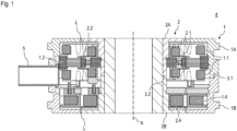
- the modular resolver 4 comprises two structural units rotatable about an axis A, namely a stator 1 as the first structural unit and a rotor 2 as the second structural unit.
- An air gap L is formed between the stator 1 and the rotor 2.
- the stator 1 has a first housing element 1A and a second housing element 1B, which are coupled to one another to prevent relative axial displacement and torsion.
- the first housing element 1A comprises a receptacle for a laminated core 1.2.
- Resolver windings 1.1 for example made of copper wire, which serve as receiver coils are arranged on this laminated core 1.2.
- the stator 1 has transformer windings 1.4, which are arranged in the region of the second housing element 1B.
- the relative angular position between stator 1 and rotor 2 can be determined using a corresponding resolver 4.
- the transformer windings 1.4 of stator 1 are supplied with a sinusoidal alternating current, which induces an alternating voltage with a predetermined transformation ratio in the transformer windings 2.4 of rotor 2.
- This alternating voltage is then also applied to the resolver windings 2.1 of the rotor, so that corresponding output voltages are induced in the resolver windings 1.1 of stator 1, which surround the resolver windings 2.1 of rotor 2.
- two resolver windings 1.1 of stator 1 offset by 90° two voltage signals can be tapped that are 90° out of phase and depend on the relative angular position between stator 1 and rotor 2.
- the present Resolver 4 is therefore designed as a brushless or slip-ring-free resolver.
- the Fig.1 The electrical supply and discharge lines (not shown) from the resolver windings 1.1 and the transformer windings 1.4 are led outwards through a bore or a guide sleeve 5 partially arranged in the bore from the inside of the first and second housing elements 1A, 1B led.
- the rotor 2 has a first hub element 2A and a second hub element 2B, which are also coupled to one another to prevent relative axial displacement and to prevent rotation.
- the first and second hub elements 2A, 2B are coupled to a hollow shaft, which can be fixed in a rotationally fixed manner, for example, to a motor shaft (not shown), the angular position of which is to be determined.
- the first hub element 2A comprises a receptacle for a laminated core 2.2, on which the resolver windings 2.1 are arranged.
- the rotor 2 has transformer windings 2.4, which are arranged in the region of the second hub element 2B.
- the resolver windings 2.1 together with the laminated core 2.2 are usually potted.
- the potting compound is not shown in the drawing for the sake of clarity. Fig. 1 shown.
- the coupling between the first housing element 1A and the second housing element 1B, or between the first hub element 2A and the second hub element 2B, is achieved, for example, by a positive and non-positive connection technique.
- a material connection technique is used for the coupling of the housing elements 1A, 1B, or for the coupling of the hub elements 2A, 2B, for example, by laser welding or adhesive bonding.
- the resolver 4 shown is a resolver with a modular design, meaning it can be assembled and manufactured according to the building block principle. Almost every subcomponent of the resolver 4 is available in different embodiments, with all embodiments of a subcomponent not exceeding a predefined installation space and adhering to other standards.
- the resolver windings 1.1 and 1.2 can include embodiments with different winding patterns.
- first housing element 1A and the second housing element 1B are made of different materials, and the first hub element 2A and the second hub element 2B are made of different materials. In this way, the propagation of the magnetic flux emanating from the current-carrying transformer windings 1.4 and 2.4 can be specifically influenced within the resolver 4.
- the first housing element 1A and the first hub element 2A are made of an identical, amagnetic, i.e., non-magnetic, material. Suitable materials include, for example, amagnetic steels, aluminum, aluminum alloys, or plastics.
- the second housing element 1B and the second hub element 2B are made of an identical material that is magnetic. Magnetic steels, for example, are suitable for this purpose.
- the transformer magnetic field remains primarily in the area of the transformer windings 1.4, 2.4, as it is preferably coupled into the magnetic second housing element 1B and the magnetic second hub element 2B.
- the non-magnetic first housing element 1A and the non-magnetic first hub element 2A conduct the magnetic flux of the transformer magnetic field to little or no extent, whereby this part of the resolver 4, with the resolver windings 1.1, 1.2, is magnetically decoupled. This eliminates the need for an additional shielding element between the transformer windings 1.4, 2.4 and the resolver windings 1.1, 2.1.
- the housing elements 1A, 1B and the hub elements 2A, 2B shield the resolver windings 1.1, 2.1 and the transformer windings 1.4, 2.4, respectively, so that the interior of the resolver 4 is protected from contamination from all sides.
- the housing elements 1A, 1B and the hub elements 2A, 2B are largely rotationally symmetrical and have a largely identical longitudinal extension in the axial direction, relative to the axis A. This allows the use of semi-finished products or blanks for these subcomponents, with the final finished part being produced only during final processing by forming the subcomponent-specific features. In this way, either a first housing element 1A or a second housing element 1B can be manufactured from a corresponding semi-finished product.
- the first housing element 1A and the first hub element 2A can be made of a non-magnetic material
- the second housing element 1B and the second hub element 2B can be made of a magnetic material.
- the resolver windings 1.1, 2.1 would be primarily protected from external magnetic interference fields.
- an external magnetic interference field would couple into the second housing element 1B and the second hub element 2B, and the magnetic flux would remain therein.
- resolvers within a series can be manufactured and assembled in a standardized manner, even if individual components of the finished resolvers are not identical.
Landscapes
- Engineering & Computer Science (AREA)
- Power Engineering (AREA)
- Physics & Mathematics (AREA)
- General Physics & Mathematics (AREA)
- Transmission And Conversion Of Sensor Element Output (AREA)
Abstract
Description
- Die Erfindung betrifft ein Resolver mit modularem Aufbau gemäß dem Patentanspruch 1.
- Als Resolver bezeichnet man in der Elektrotechnik einen elektromagnetischen Messumformer zur Umwandlung der Winkellage eines Rotors in eine elektrische Größe bzw. in elektrische Signale. Der Begriff Resolver umfasst in dieser Anwendung auch Messumformer, die als Synchro oder Drehmelder oder als RVDT (rotary variable differential transformer) bezeichnet werden.
- Häufig sind bei einem bürstenlosen Resolver in einem Gehäuse mehrere Wicklungen angeordnet. Diese Wicklungen umfassen zum einen Resolverwicklungen, bestehend aus Statorwicklungen und Rotorwicklungen und zum anderen Transformatorwicklungen, welche auf dem Rotor sowie auf dem Stator angeordnet sind. Um einen unerwünschten Magnetfluss zwischen Resolverwicklungen und Transformatorwicklungen zu minimieren, befinden sich die Resolverwicklungen in einem ersten distalen Bereich des Resolvers, während sich die Transformatorwicklungen möglichst weit entfernt, im gegenüberliegenden zweiten distalen Bereich des Resolvers befinden.
- Solche Resolver werden in der Regel in großen Stückzahlen hergestellt, so dass eine einfache und möglichst vollautomatische Fertigung erwünscht ist.
- Aus der Offenlegungsschrift
EP1667313 A1 ist ein Resolver bekannt, welcher eine einteilige Rotornabe und ein mehrteiliges Statorgehäuse umfasst, wobei Rotornabe und Statorgehäuse aus einem identischen Werkstoff gefertigt sind. Magnetische Störreinflüsse zwischen Resolverwicklungen sowie Transformatorwicklungen werden über eine zusätzliche Abschirmstruktur minimiert. - Ein solcher Aufbau hat Nachteile hinsichtlich der Messgenauigkeit und ist zudem nur mit relativ großem Aufwand herzustellen bzw. zu montieren.
- Der Erfindung liegt die Aufgabe zugrunde ein Resolver zu schaffen, welcher eine vergleichsweise erhöhte Messgenauigkeit aufweist und sich zusätzlich vergleichsweise optimal in großen Stückzahlen fertigen lässt.
- Diese Aufgabe wird erfindungsgemäß durch die Merkmale des Anspruchs 1 gelöst. Vorteilhafte Ausgestaltungen und Weiterbildungen sind in den jeweils abhängigen Ansprüchen angegeben.
- Der erfindungsgemäße Resolver umfasst zwei um eine Achse relativ zueinander drehbare Baueinheiten, wobei der Resolver zur Bestimmung der relativen Winkellage zwischen den beiden Baueinheiten geeignet ist. Zumindest eine der beiden Baueinheiten weist mehrere Resolverwicklungen und Transformatorwicklungen auf. Die erste Baueinheit umfasst ein erstes Gehäuseelement und ein zweites Gehäuseelement. Die zweite Baueinheit umfasst ein erstes Nabenelement und ein zweites Nabenelement. Das ersten und zweite Gehäuseelement sind an zumindest einer Verbindungsstelle, welche sich in die Umfangsrichtung des ersten und zweiten Gehäuseelements erstreckt, miteinander gekoppelt bzw. miteinander verbunden. Ergänzend oder alternativ sind auch das erste und zweite Nabenelement an zumindest einer weiteren Verbindungsstelle, welche sich in die Umfangsrichtung des ersten und zweiten Nabenelements erstreckt, miteinander gekoppelt.
- Die Kopplung zwischen dem ersten und zweiten Gehäuseelement bzw. zwischen dem ersten und zweiten Nabenelement verhindert insbesondere eine axiale Verschiebung der miteinander gekoppelten Elemente. Es soll dabei eine relative axiale Verschiebung von erstem Gehäuseelement zum zweiten Gehäuseelement verhindert werden bzw. eine relative axiale Verschiebung von erstem Nabenelement zum zweiten Nabenelement.
- In weiterer Ausgestaltung ist bzw. sind das erste Gehäuseelement und ergänzend oder alternativ das erste Nabenelement aus einem ersten Material hergestellt. Zusätzlich ist bzw. sind das zweite Gehäuseelement und ergänzend oder alternativ das zweite Nabenelement aus einem zweiten Material hergestellt.
- Mit Vorteil ist das erste Material ein amagnetischer Werkstoff und das zweite Material ein magnetischer Werkstoff.
- Mit einem magnetischen Material bzw. magnetischen Werkstoff ist hierbei insbesondere ein ferromagnetischer Werkstoff gemeint, welcher eine hohe Permeabilität sowie eine geringe Remanenz aufweist.
- Mit einem amagnetischen Material bzw. amagnetischen Werkstoff ist ein nicht ferromagnetischer Werkstoff gemeint, welcher weitestgehend nicht magnetisierbar ist, d. h. eine geringe Permeabilität sowie eine hohe Remanenz aufweist.
- Gemäß einer vorteilhaften Weiterbildung der Erfindung ist die Kopplung zwischen dem ersten und zweiten Gehäuseelement verdrehsicher bzw. drehfest ausgebildet. Ergänzend oder alternativ ist auch bzw. nur die Kopplung zwischen dem ersten und zweiten Nabenelement verdrehsicher bzw. drehfest ausgebildet.
- Mit Vorteil ist die Kopplung zwischen dem ersten und zweiten Gehäuseelement durch eine formschlüssige, kraftschlüssige und ergänzend oder alternativ stoffschlüssige Verbindungstechnik ausgebildet. Ergänzend oder alternativ ist auch bzw. nur die Kopplung zwischen dem ersten und zweiten Nabenelement durch eine formschlüssige, kraftschlüssige und ergänzend oder alternativ stoffschlüssige Verbindungstechnik ausgebildet.
- Mit Vorteil sind zumindest das erste und zweite Nabenelement rotationssymmetrisch ausgebildet.
- Gemäß einer vorteilhaften Weiterbildung der Erfindung sind die Transformatorwicklungen im Bereich des zweiten Gehäuseelements und des zweiten Nabenelements angeordnet und die Resolverwicklungen im Bereich des ersten Gehäuseelements und des ersten Nabenelements.
- Unter dem Bereich des ersten Gehäuseelements und des ersten Nabenelements ist die Anordnung der Resolverwicklungen auf den Bauteilen selbst zu verstehen, oder eine Anordnung der Resolverwicklungen innerhalb einer Kavität, welche durch eines oder mehrerer diese Bauteile ausgebildet wird. Analog hierzu ist unter dem Bereich des zweiten Gehäuseelements und des zweiten Nabenelements eine Anordnung der Transformatorwicklungen auf den Bauteilen selbst oder eine Anordnung der Transformatorwicklungen innerhalb eines durch diese Bauteile ausgebildeten Kavität zu verstehen.
- In weiterer Ausgestaltung sind die Gehäuseelemente und die Nabenelemente derart ausgebildet und angeordnet, dass zwischen den Baueinheiten ein Luftspalt ausgebildet ist und zumindest die Resolverwicklungen und die Transformatorwicklungen durch die Gehäuseelemente und die Nabenelemente von allen Seiten abgeschirmt werden.
- Gemäß einem weiteren Aspekt umfasst die Erfindung eine Resolver-Baureihe. Demnach ist jeder Resolver modular aufgebaut und umfasst zwei um eine Achse relativ zueinander drehbare Baueinheiten. Jeder Resolver der Baureihe ist im Betrieb zur Bestimmung der relativen Winkellage seiner beiden Baueinheiten geeignet. Zumindest eine der beiden Baueinheiten weist stets mehrere Resolverwicklungen und Transformatorwicklungen auf. Die erste Baueinheit umfasst stets ein erstes Gehäuseelement und ein zweites Gehäuseelement. Die zweite Baueinheit umfasst stets ein erstes Nabenelement und ein zweites Nabenelement. Die ersten und zweiten Gehäuseelemente sind an zumindest einer Verbindungsstelle, welche sich in die Umfangsrichtung des ersten und zweiten Gehäuseelements erstreckt, miteinander gekoppelt. Ergänzend können auch das erste und zweite Nabenelement an zumindest einer weiteren Verbindungsstelle, welche sich in die Umfangsrichtung des ersten und zweiten Nabenelements erstreckt, miteinander gekoppelt sein.
- Resolver innerhalb der Baureihe werden gemäß dem Baukastenprinzip zusammengebaut, wobei Teilkomponenten bedarfsabhängig aus einer Reihe an unterschiedlichen Ausführungsformen ausgewählt werden.
- Zusätzliche vorteilhafte Ausgestaltungen der Erfindung sind den abhängigen Ansprüchen zu entnehmen.
- Es zeigt die
- Fig. 1
- eine Längsschnittdarstellung eines Resolvers.
- Die Erfindung wird nachstehend auch hinsichtlich weiterer Merkmale und Vorteile anhand der Beschreibung eines Ausführungsbeispiels und unter Bezugnahme auf die beiliegende, schematische Zeichnung näher erläutert.
- Der Erfindung liegt die Erkenntnis zugrunde, dass bei bürstenlosen Resolvern, bei denen innerhalb des Resolvergehäuses sowohl Transformatorwicklungen als auch Resolverwicklungen unmittelbar benachbart angeordnet sind, ein sogenanntes "Übersprechen" auftritt. Dabei wirken die elektromagnetischen Felder der Transformatorwicklungen als Störeinfluss auf die Resolverwicklungen, was Einbußen bei der Messgenauigkeit zur Folge hat. Mit der Erfindung wird nun durch geeignete Materialwahl und konstruktive Gestaltung der Gehäuse- und Nabenelemente von Stator und Rotor eine vereinfachte Herstellung sowie eine Entkopplung bzw. Abschirmung des Transformatormagnetfeldes gegenüber den Resolverwicklungen und damit eine Reduzierung des Übersprechens erreicht.
- Gemäß der
Fig. 1 umfasst der modular aufgebaute Resolver 4 zwei um eine Achse A drehbare Baueinheiten, nämlich einen Stator 1 als erste Baueinheit und einen Rotor 2 als zweite Baueinheit. Zwischen Stator 1 und Rotor 2 ist ein Luftspalt L ausgebildet. Der Stator 1 weist ein erstes Gehäuseelement 1A und ein zweites Gehäuseelement 1B auf, welche gegen eine relative Axialverschiebung sowie verdrehsicher miteinander gekoppelt sind. Das erste Gehäuseelement 1A umfasst eine Aufnahme für ein Blechpaket 1.2. An diesem Blechpaket 1.2 sind Resolverwicklungen 1.1, beispielsweise aus Kupferdraht, angeordnet, die als Empfängerspulen dienen. Ferner weist der Stator 1 Transformatorwicklungen 1.4 auf, welche im Bereich des zweiten Gehäuseelements 1B angeordnet sind. - Durch einen entsprechenden Resolver 4 kann die relative Winkellage zwischen dem Stator 1 und dem Rotor 2 bestimmt werden. Dazu werden die Transformatorwicklungen 1.4 des Stators 1 mit einem sinusförmigen Wechselstrom beaufschlagt, der in den Transformatorwicklungen 2.4 des Rotors 2 eine Wechselspannung mit einem vorgegebenen Transformationsverhältnis induziert. Diese Wechselspannung liegt damit dann auch an den Resolverwicklungen 2.1 des Rotors an, sodass in den Resolverwicklungen 1.1 des Stators 1, welche die Resolverwicklungen 2.1 des Rotors 2 umschließen, entsprechende Ausgangsspannungen induziert werden. Bei Verwendung von zwei um 90° versetzten Resolverwicklungen 1.1 des Stators 1 können dann zwei um 90° phasenverschobene Spannungssignale abgegriffen werden, die von der relativen Winkellage zwischen Stator 1 und Rotor 2 abhängen. Der vorliegende Resolver 4 ist somit als bürstenloser bzw. schleifringloser Resolver ausgeführt.
- Die in
Fig.1 nicht dargestellten elektrischen Zu- bzw. Ableitungen aus den Resolverwicklungen 1.1 und den Transformatorwicklungen 1.4 werden durch eine Bohrung bzw. eine in der Bohrung teilweise angeordnete Führungstülle 5 vom Inneren des ersten und zweiten Gehäuseelements 1A, 1B nach außen geführt. - Der Rotor 2 weist ein erstes Nabenelement 2A und ein zweites Nabenelement 2B auf, welche ebenfalls gegen eine relative Axialverschiebung sowie verdrehsicher miteinander gekoppelt sind. Im gezeigten Ausführungsbeispiel sind das erste und das zweite Nabenelement 2A, 2B mit einer Hohlwelle gekoppelt, welche beispielsweise mit einer nicht dargestellten Motorwelle, deren Winkellage zu bestimmen ist, drehfest fixiert werden kann. Das erste Nabenelement 2A umfasst eine Aufnahme für ein Blechpaket 2.2, an dem die Resolverwicklungen 2.1 angeordnet sind. Ferner weist der Rotor 2 Transformatorwicklungen 2.4 auf, welche im Bereich des zweiten Nabenelements 2B angeordnet sind. Üblicherweise werden die Resolverwicklungen 2.1 samt Blechpaket 2.2 vergossen. Die Vergussmasse ist der Übersichtlichkeit halber nicht in
Fig. 1 dargestellt. - Statt dem Blechpaket 1.2 und dem Blechpaket 2.2 können auch alternative Teilkomponenten genutzt werden, welche eine Bündelung elektromagnetischer Wellen begünstigen.
- Die Kopplung zwischen dem ersten Gehäuseelement 1A und dem zweiten Gehäuseelement 1B bzw. zwischen dem ersten Nabenelement 2A und dem zweiten Nabenelement 2B erfolgt beispielsweise durch eine form- und kraftschlüssige Verbindungstechnik. Vorzugsweise kommt bei der Kopplung der Gehäuseelemente 1A, 1B bzw. bei der Kopplung der Nabenelemente 2A, 2B eine stoffschlüssige Verbindungstechnik zum Einsatz, beispielsweise durch Laserschweißen oder durch Verkleben.
- Bei dem in
Fig. 1 gezeigten Resolver 4 handelt es sich um einen Resolver mit modularem Aufbau, d. h. dieser kann nach dem Baukastenprinzip zusammengestellt und hergestellt werden. Nahezu jede Teilkomponente des Resolvers 4 liegt in unterschiedlichen Ausführungsformen vor, wobei alle Ausführungsformen einer Teilkomponente einen vordefinierten Bauraum nicht überschreiten und weitere Standards einhalten. So können beispielsweise die Resolverwicklungen 1.1, 1.2 Ausführungsformen mit unterschiedlichen Wicklungsschemata umfassen. - Durch die gezielte Wahl der Ausführungsformen einzelner Teilkomponenten können auch vorteilhafte synergetische Effekte erzielt werden. So ist es besonders vorteilhaft, wenn das erste Gehäuseelement 1A und das zweite Gehäuseelement 1B aus unterschiedlichen Materialen bestehen und das erste Nabenelement 2A und das zweite Nabenelement 2B aus unterschiedlichen Materialen bestehen. Auf diese Weise kann die Ausbreitung des magnetischen Flusses, welcher von den stromdurchflossenen Transformatorwicklungen 1.4 und 2.4 ausgeht, innerhalb des Resolvers 4 gezielt beeinflusst werden.
- Im vorliegenden Ausführungsbeispiel in
Fig. 1 bestehen das erste Gehäuseelement 1A und das erste Nabenelement 2A aus einem identischen, amagnetischen, d. h. nichtmagnetischen, Werkstoff. Hierfür geeignet sind beispielsweise amagnetische Stähle, Aluminium, Aluminiumlegierungen oder Kunststoffe. - Das zweite Gehäuseelement 1B und das zweite Nabenelement 2B besteht aus einem identischen Werkstoff, welcher magnetisch ist. Hierfür geeignet sind beispielsweise magnetische Stähle.
- Durch diese Ausgestaltung verbleibt das Transformator-Magnetfeld primär im Bereich der Transformatorwicklungen 1.4, 2.4, da es sich bevorzugt in das magnetische zweite Gehäuseelement 1B und das magnetische zweite Nabenelement 2B einkoppelt. Das amagnetische erste Gehäuseelement 1A und das amagnetische erste Nabenelement 2A leiten den magnetischen Fluss des Transformator-Magnetfelds kaum bis gar nicht, wodurch dieser Teil des Resolvers 4, mit den Resolverwicklungen 1.1, 1.2, magnetisch entkoppelt ist. Auf diese Weise kann auf ein zusätzliches Abschirmelement zwischen den Transformatorwicklungen 1.4, 2.4 und den Resolverwicklungen 1.1, 2.1 verzichtet werden.
- Die Gehäuseelemente 1A, 1B und die Nabenelemente 2A, 2B schirmen die Resolverwicklungen 1.1, 2.1 bzw. die Transformatorwicklungen 1.4, 2.4 ab, sodass das Innere des Resolvers 4 von allen Seiten gegen Verschmutzung geschützt ist.
- Im Vorgestellten Ausführungsbeispiel sind die Gehäuseelemente 1A, 1B bzw. die Nabenelemente 2A, 2B weitestgehend rotationssymmetrisch ausgebildet und weisen weitestgehend eine identische Längserstreckung in axialer Richtung, bezüglich der Achse A, auf. Dies ermöglich die Verwendung von Halbzeugen oder Rohlingen für diese Teilkomponenten, wobei erst bei der Endverarbeitung durch Ausbilden der Teilkomponenten-spezifischen Merkmale das finale Fertigteil hergestellt wird. Auf diese Weise kann entweder ein erstes Gehäuseelement 1A oder ein zweites Gehäuseelement 1B aus einem entsprechenden Halbzeug hergestellt werden.
- Alternativ kann auch das erste Gehäuseelement 1A und das erste Nabenelement 2A aus einem amagnetischen Werkstoff bestehen und das zweite Gehäuseelement 1B und das zweite Nabenelement 2B aus einem magnetischen Werkstoff. In diesem Fall wären die Resolverwicklungen 1.1, 2.1 primär gegenüber externen Störmagnetfeldern geschützt. Bei dieser alternativen Ausführungsform würde sich ein externes Störmagnetfeld in das zweite Gehäuseelement 1B und das zweite Nabenelement 2B einkoppeln und der magnetische Fluss darin verbleiben.
- Ein weiterer Vorteil ist, dass die Resolver innerhalb einer Baureihe standardisiert gefertigt und zusammengebaut werden können, auch wenn einzelne Teilkomponenten der fertigen Resolver nicht identisch sind.
Claims (8)
- Modular aufgebauter Resolver (4) umfassend zwei um eine Achse (A) relativ zueinander drehbare Baueinheiten (1; 2), wobei der Resolver (4) zur Bestimmung der relativen Winkellage zwischen den beiden Baueinheiten (1; 2) geeignet ist und zumindest eine der Baueinheiten (1; 2) Resolverwicklungen (1.1; 2.1) und Transformatorwicklungen (1.4; 2.4) aufweist,wobei die erste Baueinheit (1) ein erstes Gehäuseelement (1A) und ein zweites Gehäuseelement (1B) umfasst,wobei die zweite Baueinheit (2) ein erstes Nabenelement (2A) und ein zweites Nabenelement (2B) umfasst,wobei das erste und zweite Gehäuseelement (1A; 1B) an zumindest einer sich in Umfangsrichtung erstreckenden Verbindungsstelle (3.1) gekoppelt sind und/oder das erste und zweite Nabenelement (2A; 2B) an zumindest einer sich in Umfangsrichtung erstreckenden weiteren Verbindungsstelle (3.2) gekoppelt sind.
- Resolver gemäß Anspruch 1, wobei das erste Gehäuseelement (1A) und/oder das erste Nabenelement (2A) aus einem ersten Material hergestellt ist/sind und das zweite Gehäuseelement (1B) und/oder das zweite Nabenelement (2B) aus einem zweiten Material.
- Resolver gemäß Anspruch 2, wobei das erste Material ein amagnetischer Werkstoff und das zweite Material ein magnetischer Werkstoff ist.
- Resolver gemäß zumindest einem der vorhergehenden Ansprüche, wobei die Kopplung zwischen dem ersten und zweiten Gehäuseelement (1A, 1B) verdrehsicher ausgebildet ist und/oder die Kopplung zwischen dem ersten und zweiten Nabenelement (2A, 2B) verdrehsicher ausgebildet ist.
- Resolver gemäß zumindest einem der vorhergehenden Ansprüche, wobei die Kopplung zwischen dem ersten und zweiten Gehäuseelement (1A, 1B) formschlüssig, kraftschlüssig und/oder stoffschlüssig ausgebildet ist und/oder
die Kopplung zwischen dem ersten und zweiten Nabenelement (2A, 2B) formschlüssig, kraftschlüssig und/oder stoffschlüssig ausgebildet ist. - Resolver gemäß zumindest einem der vorhergehenden Ansprüche, wobei zumindest das erste und zweite Nabenelement (2A; 2B) rotationssymmetrisch ausgebildet sind.
- Resolver gemäß zumindest einem der vorhergehenden Ansprüche, wobei die Transformatorwicklungen (1.4; 2.4) im Bereich des zweiten Gehäuseelements (1B) und des zweiten Nabenelements (2B) angeordnet sind und die Resolverwicklungen (1.1; 2.1) im Bereich des ersten Gehäuseelements (1A) und des ersten Nabenelements (2A).
- Resolver gemäß zumindest einem der vorhergehenden Ansprüche, wobei die Gehäuseelemente (1A; 1B) und Nabenelemente (2A; 2B) derart ausgebildet und angeordnet sind, dass zwischen den Baueinheiten (1; 2) ein Luftspalt (L) ausgebildet ist und zumindest die Resolverwicklungen und die Transformatorwicklungen durch die Gehäuseelemente (1A, 1B) und die Nabenelemente (2A, 2B) von allen Seiten abgeschirmt werden.
Priority Applications (5)
| Application Number | Priority Date | Filing Date | Title |
|---|---|---|---|
| EP23211749.9A EP4560268B1 (de) | 2023-11-23 | 2023-11-23 | Resolver |
| DE102024003359.9A DE102024003359A1 (de) | 2023-11-23 | 2024-10-15 | Resolver |
| JP2024188852A JP2025085069A (ja) | 2023-11-23 | 2024-10-28 | レゾルバ |
| US18/944,239 US20250175066A1 (en) | 2023-11-23 | 2024-11-12 | Resolver |
| CN202411665646.1A CN120027834A (zh) | 2023-11-23 | 2024-11-20 | 分解器 |
Applications Claiming Priority (1)
| Application Number | Priority Date | Filing Date | Title |
|---|---|---|---|
| EP23211749.9A EP4560268B1 (de) | 2023-11-23 | 2023-11-23 | Resolver |
Publications (3)
| Publication Number | Publication Date |
|---|---|
| EP4560268A1 true EP4560268A1 (de) | 2025-05-28 |
| EP4560268A8 EP4560268A8 (de) | 2025-10-22 |
| EP4560268B1 EP4560268B1 (de) | 2026-05-20 |
Family
ID=88965286
Family Applications (1)
| Application Number | Title | Priority Date | Filing Date |
|---|---|---|---|
| EP23211749.9A Active EP4560268B1 (de) | 2023-11-23 | 2023-11-23 | Resolver |
Country Status (5)
| Country | Link |
|---|---|
| US (1) | US20250175066A1 (de) |
| EP (1) | EP4560268B1 (de) |
| JP (1) | JP2025085069A (de) |
| CN (1) | CN120027834A (de) |
| DE (1) | DE102024003359A1 (de) |
Citations (3)
| Publication number | Priority date | Publication date | Assignee | Title |
|---|---|---|---|---|
| EP1667313A1 (de) | 2003-09-24 | 2006-06-07 | Tamagawa Seiki Co. Ltd. | Rotationsdetektor-abschirmstruktur des bürstenlosen typs |
| DE102009020327A1 (de) * | 2009-05-07 | 2010-11-11 | Ltn Servotechnik Gmbh | Resolver |
| DE102014224081A1 (de) * | 2014-02-27 | 2015-08-27 | Ltn Servotechnik Gmbh | Resolver |
Family Cites Families (2)
| Publication number | Priority date | Publication date | Assignee | Title |
|---|---|---|---|---|
| JP3643960B2 (ja) * | 2002-10-09 | 2005-04-27 | ミネベア株式会社 | 回転トランス型レゾルバの巻線固定構造 |
| JP7625873B2 (ja) * | 2020-01-27 | 2025-02-04 | 日本精工株式会社 | モータ |
-
2023
- 2023-11-23 EP EP23211749.9A patent/EP4560268B1/de active Active
-
2024
- 2024-10-15 DE DE102024003359.9A patent/DE102024003359A1/de active Pending
- 2024-10-28 JP JP2024188852A patent/JP2025085069A/ja active Pending
- 2024-11-12 US US18/944,239 patent/US20250175066A1/en active Pending
- 2024-11-20 CN CN202411665646.1A patent/CN120027834A/zh active Pending
Patent Citations (3)
| Publication number | Priority date | Publication date | Assignee | Title |
|---|---|---|---|---|
| EP1667313A1 (de) | 2003-09-24 | 2006-06-07 | Tamagawa Seiki Co. Ltd. | Rotationsdetektor-abschirmstruktur des bürstenlosen typs |
| DE102009020327A1 (de) * | 2009-05-07 | 2010-11-11 | Ltn Servotechnik Gmbh | Resolver |
| DE102014224081A1 (de) * | 2014-02-27 | 2015-08-27 | Ltn Servotechnik Gmbh | Resolver |
Also Published As
| Publication number | Publication date |
|---|---|
| EP4560268A8 (de) | 2025-10-22 |
| US20250175066A1 (en) | 2025-05-29 |
| CN120027834A (zh) | 2025-05-23 |
| DE102024003359A1 (de) | 2025-05-28 |
| EP4560268B1 (de) | 2026-05-20 |
| JP2025085069A (ja) | 2025-06-04 |
Similar Documents
| Publication | Publication Date | Title |
|---|---|---|
| DE69908786T2 (de) | Bürstenlosen Motor mit Vorrichtung zur Ermittlung der Rotorstellung | |
| DE69204771T2 (de) | Einrichtung zur Messung der Winkellage eines Rotors in bezüglich eines Stators. | |
| EP1670121B1 (de) | Elektrische Maschine, insbesondere bürstenloser Gleichstrommotor | |
| EP2449276B1 (de) | Lager mit energieerzeugungseinheit | |
| EP0554900A1 (de) | Induktiv arbeitender Stellungsdetektor für einen Elektromotor | |
| DE60215414T2 (de) | Apparat zur Erfassung einer relativen Winkelpositionsänderung | |
| DE102004056049A1 (de) | Sensor und Verfahren zur Herstellung eines Sensors | |
| DE102013204871A1 (de) | Verfahren und Winkelsensor zur kontaktlosen Messung eines Winkels | |
| WO2009015496A1 (de) | Elektromotor mit rotorpositionssensoranordnung | |
| DE102019125309A1 (de) | Sensorsystem zur Erfassung einer Winkellage und eines Linearwegs | |
| DE10027095B4 (de) | Drehmomentdetektoranordnung | |
| WO2023072736A1 (de) | System mit elektrischem drehtransformator | |
| EP2149784B1 (de) | Magnetisches Wegsensorsystem | |
| DE102022104387A1 (de) | Resolver mit variabler Reluktanz | |
| DE102012102855A1 (de) | Verfahren und Anordnung zur Positionsbestimmung eines Bauteils sowie Sensor | |
| DE102024003359A1 (de) | Resolver | |
| DE4013429C2 (de) | Spannungsdetektor | |
| EP2427732B1 (de) | Resolver | |
| EP3714532B1 (de) | Verfahren und anordnung zum bestimmen von mindestens einer eigenschaft einer elektrischen maschine | |
| DE102018108019B4 (de) | Messanordnung zur Messung einer Drehlage und/oder einer Drehzahl einer Kurbelwelle | |
| DE102017222402B4 (de) | Drehwinkelmesseinrichtung | |
| EP2940432B1 (de) | Winkelsensor | |
| EP2376872B1 (de) | Resolverbauteil und damit ausgestatteter resolver | |
| DE102019124226A1 (de) | Elektrische Maschine mit Schultern zwischen mehreren Leitern und Laschen eines Wicklungsaufnahmebereiches eines Stators oder eines Rotors | |
| DE102022208616A1 (de) | Induktive Sensoranordnung zur Ermittlung eines Drehwinkels oder eines Differenzwinkels |
Legal Events
| Date | Code | Title | Description |
|---|---|---|---|
| STAA | Information on the status of an ep patent application or granted ep patent |
Free format text: STATUS: EXAMINATION IS IN PROGRESS |
|
| PUAI | Public reference made under article 153(3) epc to a published international application that has entered the european phase |
Free format text: ORIGINAL CODE: 0009012 |
|
| 17P | Request for examination filed |
Effective date: 20231123 |
|
| AK | Designated contracting states |
Kind code of ref document: A1 Designated state(s): AL AT BE BG CH CY CZ DE DK EE ES FI FR GB GR HR HU IE IS IT LI LT LU LV MC ME MK MT NL NO PL PT RO RS SE SI SK SM TR |
|
| GRAP | Despatch of communication of intention to grant a patent |
Free format text: ORIGINAL CODE: EPIDOSNIGR1 |
|
| STAA | Information on the status of an ep patent application or granted ep patent |
Free format text: STATUS: GRANT OF PATENT IS INTENDED |
|
| RIN1 | Information on inventor provided before grant (corrected) |
Inventor name: SCHUECK, ADRIAN |
|
| INTG | Intention to grant announced |
Effective date: 20250708 |
|
| GRAS | Grant fee paid |
Free format text: ORIGINAL CODE: EPIDOSNIGR3 |
|
| GRAA | (expected) grant |
Free format text: ORIGINAL CODE: 0009210 |
|
| STAA | Information on the status of an ep patent application or granted ep patent |
Free format text: STATUS: THE PATENT HAS BEEN GRANTED |
|
| RAP1 | Party data changed (applicant data changed or rights of an application transferred) |
Owner name: DR. JOHANNES HEIDENHAIN GMBH |
|
| AK | Designated contracting states |
Kind code of ref document: B1 Designated state(s): AL AT BE BG CH CY CZ DE DK EE ES FI FR GB GR HR HU IE IS IT LI LT LU LV MC ME MK MT NL NO PL PT RO RS SE SI SK SM TR |
|
| REG | Reference to a national code |
Ref country code: CH Ref legal event code: F10 Free format text: ST27 STATUS EVENT CODE: U-0-0-F10-F00 (AS PROVIDED BY THE NATIONAL OFFICE) Effective date: 20260520 Ref country code: GB Ref legal event code: FG4D Free format text: NOT ENGLISH |
|
| REG | Reference to a national code |
Ref country code: DE Ref legal event code: R096 Ref document number: 502023004157 Country of ref document: DE |