EP1667313A1 - Brush-less type rotation detector shielding structure - Google Patents
Brush-less type rotation detector shielding structure Download PDFInfo
- Publication number
- EP1667313A1 EP1667313A1 EP04773202A EP04773202A EP1667313A1 EP 1667313 A1 EP1667313 A1 EP 1667313A1 EP 04773202 A EP04773202 A EP 04773202A EP 04773202 A EP04773202 A EP 04773202A EP 1667313 A1 EP1667313 A1 EP 1667313A1
- Authority
- EP
- European Patent Office
- Prior art keywords
- section
- rotor
- stator
- shielding
- iron core
- Prior art date
- Legal status (The legal status is an assumption and is not a legal conclusion. Google has not performed a legal analysis and makes no representation as to the accuracy of the status listed.)
- Withdrawn
Links
Images


Classifications
-
- H—ELECTRICITY
- H02—GENERATION; CONVERSION OR DISTRIBUTION OF ELECTRIC POWER
- H02K—DYNAMO-ELECTRIC MACHINES
- H02K29/00—Motors or generators having non-mechanical commutating devices, e.g. discharge tubes or semiconductor devices
- H02K29/06—Motors or generators having non-mechanical commutating devices, e.g. discharge tubes or semiconductor devices with position sensing devices
- H02K29/08—Motors or generators having non-mechanical commutating devices, e.g. discharge tubes or semiconductor devices with position sensing devices using magnetic effect devices, e.g. Hall-plates, magneto-resistors
-
- H—ELECTRICITY
- H02—GENERATION; CONVERSION OR DISTRIBUTION OF ELECTRIC POWER
- H02K—DYNAMO-ELECTRIC MACHINES
- H02K11/00—Structural association of dynamo-electric machines with electric components or with devices for shielding, monitoring or protection
- H02K11/01—Structural association of dynamo-electric machines with electric components or with devices for shielding, monitoring or protection for shielding from electromagnetic fields, i.e. structural association with shields
- H02K11/012—Shields associated with rotating parts, e.g. rotor cores or rotary shafts
-
- H—ELECTRICITY
- H02—GENERATION; CONVERSION OR DISTRIBUTION OF ELECTRIC POWER
- H02K—DYNAMO-ELECTRIC MACHINES
- H02K11/00—Structural association of dynamo-electric machines with electric components or with devices for shielding, monitoring or protection
- H02K11/01—Structural association of dynamo-electric machines with electric components or with devices for shielding, monitoring or protection for shielding from electromagnetic fields, i.e. structural association with shields
- H02K11/014—Shields associated with stationary parts, e.g. stator cores
Definitions
- the present invention relates to a shielding structure for a brushless type rotation detector for detecting a rotation angle of a rotarymachine, and more particularly, to a shielding structure for a brushless type rotation detector capable of reducing interference of magnetic flux leaking from a rotation transformer with a stator iron core or a rotor iron core, and restraining a reduction in angle detection accuracy.
- Brushless type rotation detectors such as brushless resolvers or brushless synchros transmit signals using a rotation transformer constituted by a stator transformer and a rotor transformer instead of a brush.
- Figure 5 is a half section showing a structure for a brushless resolver as an example of a conventional brushless type rotation detector.
- the conventional brushless resolver includes a signal modulation section (constituted by 51 and 52, or the like described later) for modulating an output voltage induced by an excitation voltage according to a rotation angle to be detected, and a case 55 that houses the signal modulation section, and the signal modulation section includes a rotor iron core 51, a stator iron core 52, a rotor transformer 53, and a stator transformer 54, around each of which a coil is wound.
- Conventional resolvers including such a structure are disclosed in Figure 2 of the invention of "a resolver" disclosed in Japanese Patent Laid-Open No. 11-322662 (the entire document and Figure 2), and many other patent documents.
- a general conventional brushless type rotation detector is reliable.
- a rotation transformer used has a gap, which causes leakage of magnetic flux, and the magnetic flux interferes with a stator iron core or a rotor iron core to reduce angle detection accuracy of the rotation detector.
- An object of the present invention is to provide a shielding structure for a brushless type rotation detector capable of solving the problem of the above described conventional technique, reducing interference of magnetic flux leaking from a rotation transformer with a stator iron core or a rotor iron core, and restraining a reduction in angle detection accuracy.
- the inventor of the application has studied the above described problem, and found that the problem can be solved by providing a magnetic shielding plate between a rotation transformer and a stator iron core, leading to the present invention.
- the invention claimed or at least disclosed in the application as means for solving the problem is as described below.
- a magnetic shielding plate is provided between the rotation transformer and the stator iron core to reduce interference of magnetic flux leaking from the rotation transformer with the stator iron core or the rotor iron core, and restrain a reduction in angle detection accuracy of the brushless type rotation detector.
- the shielding structure for a brushless type rotation detector according to the present invention is configured as described above. This reduces interference of magnetic flux leaking from the rotation transformer with the stator iron core or the rotor iron core, and restrains a reduction in angle detection accuracy.
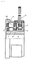
- FIG. 1 is a half section showing a configuration of a shielding structure for a brushless type rotation detector according to the present invention taking a brushless resolver as an example.
- the shielding structure is a shielding structure for a brushless type rotation detector including a signal modulation section including a rotation transformer constituted by a rotor transformer 3 and a stator transformer 4, a stator iron core 2, and a rotor iron core 1, for modulating an output voltage induced by an excitation voltage according to a rotation angle to be detected, and a case 5 that houses the signal modulation section, wherein the shielding structure includes a stator magnetic shielding section 44 that provides a magnetic shield between the stator iron core 2 and the stator transformer 4 that constitute the signal modulation section.
- stator magnetic shielding section 44 magnetic flux leaking from the stator transformer 4 toward the stator iron core 2 is shielded by the stator magnetic shielding section 44, thereby reducing interference of the magnetic flux leaking from the stator transformer 4 with the stator iron core 2, and restraining a reduction in angle detection accuracy.
- a magnetic shielding effect is prominently produced mainly in the stator iron core 2, but the magnetic shielding effect also covers the rotor iron core 1.
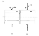
- Figure 2 is a section showing the example of the shielding structure according to the present invention.
- the shielding structure is a ring-shaped structure including a stator magnetic shielding section 44a and a securing section 40 for mounting the structure to an inner surface of the case (5) in addition to the configuration described with reference to Figure 1,
- the securing section 40 is formed into a flange shape and has an insertion hole section 48 into which a lead from the stator iron core (2) is inserted, and the stator magnetic shielding section 44a has the same height as the stator transformer (4) and the stator iron core (2) and is formed without a hole section.
- the shielding structure maybe mounted to the inside of the case of the brushless type rotation detector such as the brushless resolver by the securing section 40, thereby producing the above described magnetic shielding effect with the stator magnetic shielding section 44a.
- the lead from the stator iron core is passed through the insertion hole section 48 provided in the securing section 40.
- the shielding structure may have a ring-shaped structure with the stator magnetic shielding section integrally formed with the case.
- the stator magnetic shielding section may have the same height as the stator transformer and the stator iron core and be formed without a hole section.
- Figure 2 (b) is a section showing a shielding structure according to the present invention having a ring-shaped structure taking an example different from the example in Figure 2(a).
- the shielding structure is characterized in that a stator magnetic shielding section 44b has a height capable of also providing a shield between the rotor transformer and the rotor iron core.
- the magnetic flux leaking from the rotor transformer 3 toward the rotor iron core 1 in Figure 1 is also shielded by the stator magnetic shielding section 44b in this figure, thereby reducing interference of the magnetic flux leaking from the rotor transformer 3 with the rotor iron core 2, and restraining a reduction in angle detection accuracy.
- This provides a more effective shieldof the magnetic flux leaking from the rotation transformer to increase a reduction restraining effect of the angle detection accuracy.
- Such a configuration may be similarly used in the shielding structure integrally formed with the case besides the shielding structure as a separate component as shown in Figure 2(b).
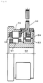
- Figure 3 is a half section showing another configuration of a shielding structure for a brushless type rotation detector according to the present invention taking a brushless resolver as an example.
- the shielding structure is a shielding structure for a brushless type rotation detector including a signal modulation section (including 3, 4, 2, and 1) for modulating an output voltage induced by an excitation voltage according to a rotation angle to be detected, and a case 5 that houses the signal modulation section, wherein the shielding structure includes a rotor magnetic shielding section 34 that provides a magnetic shield between a rotor iron core 1 and a rotor transformer 3 that constitute the signal modulation section.
- Figure 4 is a section showing the example of the shielding structure according to the present invention.
- the shielding structure is a ring-shaped structure including a rotor magnetic shielding section 34a, and a securing section 30 for mounting the structure to a surface of a rotor 18 in addition to the configuration described with reference to Figure 3, the securing section 30 is formed into a flange shape, and the rotor magnetic shielding section 34a has the same height as the rotor transformer and the rotor iron core.
- the shielding structure may be mounted to the rotor 18 of the brushless type rotation detector such as the brushless resolver by the securing section 30, thereby producing the above described magnetic shielding effect with the rotor magnetic shielding section 34a.
- the shielding structure may have a ring-shaped structure with the rotor magnetic shielding section integrally formed with the rotor.
- the rotor magnetic shielding section may have the same height as the rotor transformer and the rotor iron core.
- Figure 4 (b) is a section showing a shielding structure according to the present invention having a ring-shaped structure taking an example different from the example in Figure 4(a).
- the shielding structure is characterized in that a rotor magnetic shielding section 34b has a height capable of also providing a shield between the stator transformer and the stator iron core.
- the magnetic flux leaking from the stator transformer 4 toward the stator iron core 2 in Figure 3 is also shielded by the rotor magnetic shielding section 34b in this figure, thereby reducing interference of the magnetic flux leaking from the stator transformer 4 with the stator iron core 1, and restraining a reduction in angle detection accuracy.
- This provides a more effective shield of the magnetic flux leaking from the rotation transformer to increase a reduction restraining effect of the angle detection accuracy.
- Such a configuration may be similarly used in the shielding structure integrally formed with the rotor besides the shielding structure as a separate component as shown in Figure 4(b).
- the shielding structure for a brushless type rotation detector may include both a stator section shielding structure 44 having the stator magnetic shielding section that can provide the magnetic shield between the stator iron core 2 and the stator transformer 4 that constitute the signal modulation section, and a rotor section shielding structure 34 having the rotormagnetic shielding section that canprovide the magnetic shield between the rotor iron core 1 and the rotor transformer 3 that constitute the signal modulation section.
- a stator section shielding structure 44 having the stator magnetic shielding section that can provide the magnetic shield between the stator iron core 2 and the stator transformer 4 that constitute the signal modulation section
- a rotor section shielding structure 34 having the rotormagnetic shielding section that canprovide the magnetic shield between the rotor iron core 1 and the rotor transformer 3 that constitute the signal modulation section.
- the shielding structure for a brushless type rotation detector according to the present invention described above maybe used in a one phase excitation/two phase output brushless resolver, a two phase excitation/one phase output brushless resolver, or a two phase excitation/two phase output brushless resolver.
- the present invention includes various configurations for producing the magnetic shielding effect, and an appropriate configuration of the shielding structure may be selected therefrom according to individual specifications, use, or cost efficiency including detection accuracy required by the rotation detector to which the shielding structure is applied.
- the shielding structure for a brushless type rotation detector according to the present invention is configured as described above, thereby reducing interference of the magnetic flux leaking from the rotation transformer with the stator iron core or the rotor iron core, and restraining a reduction in angle detection accuracy.
- the shielding structure may be easily used for a brushless type rotation detector such as a brushless resolver or a brushless synchro, and is an industrially applicable invention.
Landscapes
- Engineering & Computer Science (AREA)
- Power Engineering (AREA)
- Physics & Mathematics (AREA)
- Electromagnetism (AREA)
- Transmission And Conversion Of Sensor Element Output (AREA)
Abstract
It is possible to provide a brush-less type rotation detector shielding structure capable of reducing the interference of magnetic flux leaking from a rotation transformer to a stator iron core and rotor iron core and suppressing lowering of the angle detection accuracy. As shown in Fig. 1, the shielding structure is used for a brush-less type rotation detector including: a rotation transformer having a rotor transformer (3) and stator transformer (4) ; a signal modulation section having a stator iron core (2) and a rotor iron core (1) ; and a case (5) for containing them. The shielding structure has a main configuration having a stator magnetic shielding section (44) capable of magnetically shielding between the stator iron core (2) constituting the signal modulation section and the stator transformer (4).
Description
- The present invention relates to a shielding structure for a brushless type rotation detector for detecting a rotation angle of a rotarymachine, and more particularly, to a shielding structure for a brushless type rotation detector capable of reducing interference of magnetic flux leaking from a rotation transformer with a stator iron core or a rotor iron core, and restraining a reduction in angle detection accuracy.
- Brushless type rotation detectors such as brushless resolvers or brushless synchros transmit signals using a rotation transformer constituted by a stator transformer and a rotor transformer instead of a brush.
Figure 5 is a half section showing a structure for a brushless resolver as an example of a conventional brushless type rotation detector. In the figure, the conventional brushless resolver includes a signal modulation section (constituted by 51 and 52, or the like described later) for modulating an output voltage induced by an excitation voltage according to a rotation angle to be detected, and acase 55 that houses the signal modulation section, and the signal modulation section includes arotor iron core 51, astator iron core 52, arotor transformer 53, and astator transformer 54, around each of which a coil is wound. Conventional resolvers including such a structure are disclosed in Figure 2 of the invention of "a resolver" disclosed in Japanese Patent Laid-Open No. 11-322662 (the entire document and Figure 2), and many other patent documents. - Disclosure of the Invention
- A general conventional brushless type rotation detector is reliable. However, a rotation transformer used has a gap, which causes leakage of magnetic flux, and the magnetic flux interferes with a stator iron core or a rotor iron core to reduce angle detection accuracy of the rotation detector.
- An object of the present invention is to provide a shielding structure for a brushless type rotation detector capable of solving the problem of the above described conventional technique, reducing interference of magnetic flux leaking from a rotation transformer with a stator iron core or a rotor iron core, and restraining a reduction in angle detection accuracy.
- The inventor of the application has studied the above described problem, and found that the problem can be solved by providing a magnetic shielding plate between a rotation transformer and a stator iron core, leading to the present invention. Specifically, the invention claimed or at least disclosed in the application as means for solving the problem is as described below.
-
- (1) A shielding structure for a brushless type rotation detector including: a signal modulation section for modulating an output voltage induced by an excitation voltage according to a rotation angle to be detected; and a case that houses the signal modulation section, characterized in that the shielding structure includes a stator magnetic shielding section that can provide a magnetic shield between a stator iron core and a stator transformer that constitute the signal modulation section.
- (2) The shielding structure for a brushless type rotation detector according to (1), characterized in that the shielding structure is a ring-shaped structure including the stator magnetic shielding section and a securing section for mounting the structure to an inner surface of the case, the securing section is formed into a flange shape and has an insertion hole section into which a lead from the stator iron core is inserted, and the stator magnetic shielding section has the same height as the stator transformer and the stator iron core and is formed without a hole section.
- (3) The shielding structure for a brushless type rotation detector according to (1), characterized in that the shielding structure is a ring-shaped structure including the stator magnetic shielding section integrally formed with the case, and the stator magnetic shielding section has the same height as the stator transformer and the stator iron core and is formed without a hole section.
- (4) The shielding structure for a brushless type rotation detector according to (2) or (3), characterized in that the stator magnetic shielding section has a height capable of also providing a shield between the rotor transformer and the rotor iron core.
-
- (5) A shielding structure for a brushless type rotation detector including: a signal modulation section for modulating an output voltage induced by an excitation voltage according to a rotation angle to be detected; and a case that houses the signal modulation section, characterized in that the shielding structure includes a rotor magnetic shielding section that can provide a magnetic shield between a rotor iron core and a rotor transformer that constitute the signal modulation section.
- (6) The shielding structure for a brushless type rotation detector according to (5), characterized in that the shielding structure is a ring-shaped structure including the rotor magnetic shielding section and a securing section for mounting the structure to a surface of the rotor, the securing section is formed into a flange shape, and the rotor magnetic shielding section has the same height as the rotor transformer and the rotor iron core.
- (7) The shielding structure for a brushless type rotation detector according to (5), characterized in that the shielding structure is a ring-shaped structure including the rotor magnetic shielding section integrally formed with the rotor, and the rotor magnetic shielding section has the same height as the rotor transformer and the rotor iron core.
- (8) The shielding structure for a brushless type rotation detector according to (6) or (7), characterized in that the rotor magnetic shielding section has a height capable of also providing a shield between the stator transformer and the stator iron core.
-
- (9) A shielding structure for a brushless type rotation detector including: a signal modulation section for modulating an output voltage induced by an excitation voltage according to a rotation angle to be detected; and a case that houses the signal modulation section, characterized in that the shielding structure includes a stator section shielding structure having a stator magnetic shielding section that can provide a magnetic shield between a stator iron core and a stator transformer that constitute the signal modulation section, and a rotor section shielding structure having a rotor magnetic shielding section that can provide a magnetic shield between a rotor iron core and a rotor transformer that constitute the signal modulation section.
- (10) The shielding structure for a brushless type rotation detector according to any of (1) to (9) that can be used in a one phase excitation/two phase output brushless resolver, a two phase excitation/one phase output brushless resolver, or a two phase excitation/two phase output brushless resolver.
- Specifically, according to the present invention, a magnetic shielding plate is provided between the rotation transformer and the stator iron core to reduce interference of magnetic flux leaking from the rotation transformer with the stator iron core or the rotor iron core, and restrain a reduction in angle detection accuracy of the brushless type rotation detector.
- The shielding structure for a brushless type rotation detector according to the present invention is configured as described above. This reduces interference of magnetic flux leaking from the rotation transformer with the stator iron core or the rotor iron core, and restrains a reduction in angle detection accuracy.
-
- Figure 1 is a half sect ion showing an example of a shielding structure for a brushless type rotation detector according to the present invention;
- Figure 2 is a section showing essential portions of the shielding structure in Figure 1;
- Figure 3 is a half section showing another example of a shielding structure for a brushless type rotation detector according to the present invention;
- Figure 4 is a section showing essential portions of the shielding structure in Figure 3; and
- Figure 5 is a half section showing an example of a conventional brushless type rotation detector.
- 1 ... rotor iron core, 2 ... stator iron core, 3 ... rotor transformer, 4 ... stator transformer, 5 ... case, 6 ... input/output signal wire, 8 ... axis, 18
... rotor
51 ... rotor iron core, 52 ... stator iron core, 53 ... rotor transformer, 54 ... stator transformer, 55 ... case, 56 ... input/output signal wire, 58 ... axis - Now, the present invention will be described in detail with reference to the drawings.
Figure 1 is a half section showing a configuration of a shielding structure for a brushless type rotation detector according to the present invention taking a brushless resolver as an example. In the figure, the shielding structure is a shielding structure for a brushless type rotation detector including a signal modulation section including a rotation transformer constituted by arotor transformer 3 and astator transformer 4, astator iron core 2, and arotor iron core 1, for modulating an output voltage induced by an excitation voltage according to a rotation angle to be detected, and acase 5 that houses the signal modulation section, wherein the shielding structure includes a statormagnetic shielding section 44 that provides a magnetic shield between thestator iron core 2 and thestator transformer 4 that constitute the signal modulation section. - In the figure, with such a configuration of the shielding structure, magnetic flux leaking from the
stator transformer 4 toward thestator iron core 2 is shielded by the statormagnetic shielding section 44, thereby reducing interference of the magnetic flux leaking from thestator transformer 4 with thestator iron core 2, and restraining a reduction in angle detection accuracy. A magnetic shielding effect is prominently produced mainly in thestator iron core 2, but the magnetic shielding effect also covers therotor iron core 1. - Figure 2 is a section showing the example of the shielding structure according to the present invention. In Figure 2 (a), the shielding structure is a ring-shaped structure including a stator
magnetic shielding section 44a and asecuring section 40 for mounting the structure to an inner surface of the case (5) in addition to the configuration described with reference to Figure 1, thesecuring section 40 is formed into a flange shape and has aninsertion hole section 48 into which a lead from the stator iron core (2) is inserted, and the statormagnetic shielding section 44a has the same height as the stator transformer (4) and the stator iron core (2) and is formed without a hole section. - In the figure, with such a configuration of the shielding structure, the shielding structure maybe mounted to the inside of the case of the brushless type rotation detector such as the brushless resolver by the securing
section 40, thereby producing the above described magnetic shielding effect with the statormagnetic shielding section 44a. Also, the lead from the stator iron core is passed through theinsertion hole section 48 provided in the securingsection 40. Thus, there is no need for providing a hole section in the statormagnetic shielding section 44a, and the entire stator magnetic shielding section is formed to have a uniform shielding effect, thereby preventing a reduction in magnetic shielding effect. - Irrespective of the configuration shown in Figure 2 (a), the shielding structure may have a ring-shaped structure with the stator magnetic shielding section integrally formed with the case. In this case, like Figure 2 (a), the stator magnetic shielding section may have the same height as the stator transformer and the stator iron core and be formed without a hole section. With such a configuration, the shielding structure according to the present invention may be obtained in an integral manner with the case in a case manufacturing process, which eliminates the need for a later mounting process as compared with the case where the shielding structure is manufactured as a separate component.
- Figure 2 (b) is a section showing a shielding structure according to the present invention having a ring-shaped structure taking an example different from the example in Figure 2(a). In the figure, the shielding structure is
characterized in that a statormagnetic shielding section 44b has a height capable of also providing a shield between the rotor transformer and the rotor iron core. With such a configuration, the magnetic flux leaking from thestator transformer 4 toward thestator iron core 2 as described with reference to Figure 1 is shielded by the statormagnetic shielding section 44b in this figure, thereby reducing interference of the magnetic flux leaking from thestator transformer 4 with thestator iron core 2, and restraining a reduction in angle detection accuracy. Further, the magnetic flux leaking from therotor transformer 3 toward therotor iron core 1 in Figure 1 is also shielded by the statormagnetic shielding section 44b in this figure, thereby reducing interference of the magnetic flux leaking from therotor transformer 3 with therotor iron core 2, and restraining a reduction in angle detection accuracy. This provides a more effective shieldof the magnetic flux leaking from the rotation transformer to increase a reduction restraining effect of the angle detection accuracy. Such a configuration may be similarly used in the shielding structure integrally formed with the case besides the shielding structure as a separate component as shown in Figure 2(b). - Figure 3 is a half section showing another configuration of a shielding structure for a brushless type rotation detector according to the present invention taking a brushless resolver as an example. In the figure, the shielding structure is a shielding structure for a brushless type rotation detector including a signal modulation section (including 3, 4, 2, and 1) for modulating an output voltage induced by an excitation voltage according to a rotation angle to be detected, and a
case 5 that houses the signal modulation section, wherein the shielding structure includes a rotormagnetic shielding section 34 that provides a magnetic shield between arotor iron core 1 and arotor transformer 3 that constitute the signal modulation section. - In the figure, with such a configuration of the shielding structure, magnetic flux leaking from the
rotor transformer 3 toward therotor iron core 1 is shielded by the rotormagnetic shielding section 44, thereby reducing interference of the magnetic flux leaking from therotor transformer 3 with therotor iron core 1, and restraining a reduction in angle detection accuracy. A magnetic shielding effect is prominently produced mainly in therotor iron core 1, but the magnetic shielding effect also covers thestator iron core 2. - Figure 4 is a section showing the example of the shielding structure according to the present invention. In Figure 4 (a), the shielding structure is a ring-shaped structure including a rotor
magnetic shielding section 34a, and asecuring section 30 for mounting the structure to a surface of arotor 18 in addition to the configuration described with reference to Figure 3, thesecuring section 30 is formed into a flange shape, and the rotormagnetic shielding section 34a has the same height as the rotor transformer and the rotor iron core. - In the figure, with such a configuration of the shielding structure, the shielding structure may be mounted to the
rotor 18 of the brushless type rotation detector such as the brushless resolver by the securingsection 30, thereby producing the above described magnetic shielding effect with the rotormagnetic shielding section 34a. - Irrespective of the configuration shown in Figure 4 (a), the shielding structure may have a ring-shaped structure with the rotor magnetic shielding section integrally formed with the rotor. In this case, like Figure 4 (a), the rotor magnetic shielding section may have the same height as the rotor transformer and the rotor iron core. With such a configuration, the shielding structure according to the present invention may be obtained in an integral manner with the rotor in a rotor manufacturing process, which eliminates the need for a later mounting process as compared with the case where the shielding structure is manufactured as a separate component.
- Figure 4 (b) is a section showing a shielding structure according to the present invention having a ring-shaped structure taking an example different from the example in Figure 4(a). In the figure, the shielding structure is characterized in that a rotor
magnetic shielding section 34b has a height capable of also providing a shield between the stator transformer and the stator iron core. With such a configuration, the magnetic flux leaking from therotor transformer 3 toward therotor iron core 1 as described with reference to Figure 3 is shielded by the rotormagnetic shielding section 34b in this figure, thereby reducing interference of the magnetic flux leaking from therotor transformer 3 with therotor iron core 2, and restraining a reduction in angle detection accuracy. Further, the magnetic flux leaking from thestator transformer 4 toward thestator iron core 2 in Figure 3 is also shielded by the rotormagnetic shielding section 34b in this figure, thereby reducing interference of the magnetic flux leaking from thestator transformer 4 with thestator iron core 1, and restraining a reduction in angle detection accuracy. This provides a more effective shield of the magnetic flux leaking from the rotation transformer to increase a reduction restraining effect of the angle detection accuracy. Such a configuration may be similarly used in the shielding structure integrally formed with the rotor besides the shielding structure as a separate component as shown in Figure 4(b). - As shown in Figure 3, the shielding structure for a brushless type rotation detector according to the present invention may include both a stator
section shielding structure 44 having the stator magnetic shielding section that can provide the magnetic shield between thestator iron core 2 and thestator transformer 4 that constitute the signal modulation section, and a rotorsection shielding structure 34 having the rotormagnetic shielding section that canprovide the magnetic shield between therotor iron core 1 and therotor transformer 3 that constitute the signal modulation section. With such a conf igurat ion, the magnetic flux leaking from the rotation transformer is effectively shielded both on the rotor side and the stator side, thereby producing a higher reduction restraining effect of the angle detection accuracy. - The shielding structure for a brushless type rotation detector according to the present invention described above maybe used in a one phase excitation/two phase output brushless resolver, a two phase excitation/one phase output brushless resolver, or a two phase excitation/two phase output brushless resolver. The present invention includes various configurations for producing the magnetic shielding effect, and an appropriate configuration of the shielding structure may be selected therefrom according to individual specifications, use, or cost efficiency including detection accuracy required by the rotation detector to which the shielding structure is applied.
- The shielding structure for a brushless type rotation detector according to the present invention is configured as described above, thereby reducing interference of the magnetic flux leaking from the rotation transformer with the stator iron core or the rotor iron core, and restraining a reduction in angle detection accuracy. The shielding structure may be easily used for a brushless type rotation detector such as a brushless resolver or a brushless synchro, and is an industrially applicable invention.
Claims (10)
- A shielding structure for a brushless type rotation detector comprising:a signal modulation section for modulating an output voltage induced by an excitation voltage according to a rotation angle to be detected; anda case that houses the signal modulation section,characterized in that said shielding structure includes a statormagnetic shielding section that canprovide a magnetic shield between a stator iron core and a stator transformer that constitute said signal modulation section.
- The shielding structure for a brushless type rotation detector according to claim 1, characterized in that said shielding structure is a ring-shaped structure including said stator magnetic shielding section and a securing section for mounting the structure to an inner surface of said case, said securing section is formed into a flange shape and has an insertion hole section into which a lead from said stator iron core is inserted, and said stator magnetic shielding section has the same height as said stator transformer and the stator iron core and is formed without a hole section.
- The shielding structure for a brushless type rotation detector according to claim 1, characterized in that said shielding structure is a ring-shaped structure including said stator magnetic shielding section integrally formed with said case, and said stator magnetic shielding section has the same height as said stator transformer and the stator iron core and is formed without a hole section.
- The shielding structure for a brushless type rotation detector according to claim 2 or 3, characterized in that said stator magnetic shielding section has a height capable of also providing a shield between the rotor transformer and the rotor iron core.
- A shielding structure for a brushless type rotation detector comprising:a signal modulation section for modulating an output voltage induced by an excitation voltage according to a rotation angle to be detected; anda case that houses the signal modulation section,characterized in that said shielding structure includes a rotor magnetic shielding section that can provide a magnetic shield between a rotor iron core and a rotor transformer that constitute said signal modulation section.
- The shielding structure for a brushless type rotation detector according to claim 5, characterized in that said shielding structure is a ring-shaped structure including said rotor magnetic shielding section and a securing section for mounting the structure to a surface of said rotor, said securing section is formed into a flange shape, and said rotor magnetic shielding section has the same height as said rotor transformer and the rotor iron core.
- The shielding structure for a brushless type rotation detector according to claim 5, characterized in that said shielding structure is a ring-shaped structure including said rotor magnetic shielding section integrally formed with said rotor, and said rotor magnetic shielding section has the same height as said rotor transformer and the rotor iron core.
- The shielding structure for a brushless type rotation detector according to claim 6 or 7, characterized in that said rotor magnetic shielding section has a height capable of also providing a shield between said stator transformer and the stator iron core.
- A shielding structure for a brushless type rotation detector comprising:a signal modulation section for modulating an output voltage induced by an excitation voltage according to a rotation angle to be detected; anda case that houses the signal modulation section,characterized in that said shielding structure includes a stator section shielding structure having a stator magnetic shielding section that can provide a magnetic shield between a stator iron core and a stator transformer that constitute said signal modulation section, and a rotor section shielding structure having a rotor magnetic shielding section that can provide a magnetic shield between a rotor iron core and a rotor transformer that constitute said signal modulation section.
- The shielding structure for a brushless type rotation detector according to any of claims 1 to 9 that can be used in a one phase excitation/two phase output brushless resolver, a two phase excitation/one phase output brushless resolver, or a two phase excitation/two phase output brushless resolver.
Applications Claiming Priority (2)
| Application Number | Priority Date | Filing Date | Title |
|---|---|---|---|
| JP2003331084A JP2005102374A (en) | 2003-09-24 | 2003-09-24 | Brushless type rotation detector shielding structure |
| PCT/JP2004/013556 WO2005029685A1 (en) | 2003-09-24 | 2004-09-16 | Brush-less type rotation detector shielding structure |
Publications (2)
| Publication Number | Publication Date |
|---|---|
| EP1667313A1 true EP1667313A1 (en) | 2006-06-07 |
| EP1667313A4 EP1667313A4 (en) | 2011-06-15 |
Family
ID=34373035
Family Applications (1)
| Application Number | Title | Priority Date | Filing Date |
|---|---|---|---|
| EP04773202A Withdrawn EP1667313A4 (en) | 2003-09-24 | 2004-09-16 | SHIELD STRUCTURE FOR BROKEN TYPE ROTATION DETECTOR |
Country Status (4)
| Country | Link |
|---|---|
| US (1) | US7595576B2 (en) |
| EP (1) | EP1667313A4 (en) |
| JP (1) | JP2005102374A (en) |
| WO (1) | WO2005029685A1 (en) |
Cited By (4)
| Publication number | Priority date | Publication date | Assignee | Title |
|---|---|---|---|---|
| WO2009015496A1 (en) * | 2007-07-31 | 2009-02-05 | Thyssenkrupp Presta Ag | Electric motor with rotor position sensor arrangement |
| CN103441587A (en) * | 2013-08-23 | 2013-12-11 | 中国核动力研究设计院 | Shielding structure for shielding stator core of motor and stator closed slot threading technology |
| WO2014083791A1 (en) * | 2012-11-28 | 2014-06-05 | 日本航空電子工業株式会社 | Stator |
| EP4560268A1 (en) | 2023-11-23 | 2025-05-28 | LTN Servotechnik GmbH | Resolver |
Families Citing this family (7)
| Publication number | Priority date | Publication date | Assignee | Title |
|---|---|---|---|---|
| JP5007389B2 (en) * | 2006-09-29 | 2012-08-22 | 多摩川精機株式会社 | Brushless rotation detector |
| JP2008086178A (en) * | 2006-09-29 | 2008-04-10 | Tamagawa Seiki Co Ltd | Brushless rotation detector |
| US20110062805A1 (en) * | 2009-09-17 | 2011-03-17 | Caterpillar Inc. | Switched reluctance machine with eddy current loss dampener |
| US9154019B2 (en) * | 2012-06-12 | 2015-10-06 | GM Global Technology Operations LLC | Rotor hub assembly with non-magnetic resolver shielding ring |
| WO2014039783A1 (en) * | 2012-09-07 | 2014-03-13 | Remy Technologies, Llc | Resolver with mounting structure and method |
| JP6212734B2 (en) * | 2013-11-26 | 2017-10-18 | 多摩川精機株式会社 | Resolver |
| JP2015186416A (en) * | 2014-03-26 | 2015-10-22 | 多摩川精機株式会社 | resolver coil cover |
Family Cites Families (19)
| Publication number | Priority date | Publication date | Assignee | Title |
|---|---|---|---|---|
| JPS62161573A (en) | 1986-01-13 | 1987-07-17 | Seiko Epson Corp | Print head positioning adjustment mechanism |
| JPH0619292Y2 (en) * | 1986-04-04 | 1994-05-18 | 山洋電気株式会社 | Brushless resolver |
| JPH0634565B2 (en) * | 1986-10-02 | 1994-05-02 | 工業技術院長 | Resolver Stator fixing method |
| JP2530811Y2 (en) * | 1990-07-16 | 1997-04-02 | 多摩川精機株式会社 | Case structure for rotation detector |
| JPH04326709A (en) * | 1991-04-26 | 1992-11-16 | Matsushita Electric Ind Co Ltd | Rotary transformer |
| JP2507695Y2 (en) * | 1991-06-14 | 1996-08-14 | 多摩川精機株式会社 | Resolver |
| US5394760A (en) * | 1992-06-03 | 1995-03-07 | Trw Inc. | Torque sensor for a power assist steering system |
| DE4227439C2 (en) * | 1992-08-19 | 1994-06-01 | Litton Precision Prod Int | Magnetic shield resolver |
| DE19527156C1 (en) * | 1995-07-25 | 1996-08-01 | Siemens Ag | Hollow shaft resolver with phase shift compensation |
| US6118201A (en) * | 1997-03-07 | 2000-09-12 | American Precision Industries Inc. | Resolver with leakage flux absorber |
| US6512437B2 (en) * | 1997-07-03 | 2003-01-28 | The Furukawa Electric Co., Ltd. | Isolation transformer |
| JP2001141516A (en) | 1999-11-12 | 2001-05-25 | Tamagawa Seiki Co Ltd | Resolver |
| JP2001191931A (en) * | 2000-01-06 | 2001-07-17 | Nsk Ltd | Electric power steering device |
| JP2001272204A (en) | 2000-03-24 | 2001-10-05 | Samutaku Kk | Torsion measurement device |
| JP3831841B2 (en) * | 2001-09-26 | 2006-10-11 | ミネベア株式会社 | High precision torque measuring device |
| JP2003174751A (en) * | 2001-12-06 | 2003-06-20 | Matsushita Electric Ind Co Ltd | Electric motor |
| JP2003294487A (en) * | 2002-04-02 | 2003-10-15 | Minebea Co Ltd | Rotor transformer positioning mechanism |
| JP3643960B2 (en) * | 2002-10-09 | 2005-04-27 | ミネベア株式会社 | Winding fixing structure of rotary transformer type resolver |
| JP4221253B2 (en) * | 2003-07-17 | 2009-02-12 | ミネベア株式会社 | Rotation angle sensor |
-
2003
- 2003-09-24 JP JP2003331084A patent/JP2005102374A/en active Pending
-
2004
- 2004-09-16 WO PCT/JP2004/013556 patent/WO2005029685A1/en not_active Ceased
- 2004-09-16 US US10/574,020 patent/US7595576B2/en not_active Expired - Fee Related
- 2004-09-16 EP EP04773202A patent/EP1667313A4/en not_active Withdrawn
Cited By (4)
| Publication number | Priority date | Publication date | Assignee | Title |
|---|---|---|---|---|
| WO2009015496A1 (en) * | 2007-07-31 | 2009-02-05 | Thyssenkrupp Presta Ag | Electric motor with rotor position sensor arrangement |
| WO2014083791A1 (en) * | 2012-11-28 | 2014-06-05 | 日本航空電子工業株式会社 | Stator |
| CN103441587A (en) * | 2013-08-23 | 2013-12-11 | 中国核动力研究设计院 | Shielding structure for shielding stator core of motor and stator closed slot threading technology |
| EP4560268A1 (en) | 2023-11-23 | 2025-05-28 | LTN Servotechnik GmbH | Resolver |
Also Published As
| Publication number | Publication date |
|---|---|
| WO2005029685A1 (en) | 2005-03-31 |
| US20070216242A1 (en) | 2007-09-20 |
| EP1667313A4 (en) | 2011-06-15 |
| US7595576B2 (en) | 2009-09-29 |
| JP2005102374A (en) | 2005-04-14 |
Similar Documents
| Publication | Publication Date | Title |
|---|---|---|
| EP3509187B1 (en) | Stator, and motor comprising same | |
| CN108880013B (en) | Stator structure and rotary transformer | |
| US7595576B2 (en) | Brush-less type rotation detector shielding structure | |
| US5877574A (en) | Dynamoelectric machine | |
| EP1895637A2 (en) | Electric motor | |
| WO2001045248A8 (en) | Method for determining angular position of a permanent magnet rotor of a polyphase electric motor | |
| JP2007014184A (en) | ELECTRIC MACHINE, STATOR STRUCTURE FOR ELECTRIC MACHINE, ITS MANUFACTURING METHOD, AND DC MOTOR, BRUSHLES DIRECTED MOTOR | |
| US7157820B2 (en) | Resolver | |
| US9441942B2 (en) | Resolver and multiple-rotation detector | |
| JP4924158B2 (en) | Stator and its gap winding motor | |
| CN109687677B (en) | resolver stator | |
| US20180299298A1 (en) | Brushless resolver and rotation-angle detection device | |
| JP4550496B2 (en) | Electric motor rotor | |
| US20170219385A1 (en) | Motor and resolver thereof | |
| CN105393440B (en) | Motor | |
| KR102547569B1 (en) | Motor | |
| EP2833099A1 (en) | Resolver | |
| JP4491544B2 (en) | Resolver stator structure | |
| US11552534B2 (en) | Resolver device and rotating electrical machine with resolver device | |
| US20100097055A1 (en) | Angle detector | |
| EP2466725B1 (en) | Synchronous motor with permanent magnets | |
| JP3984213B2 (en) | Tandem rotation detector | |
| US20250219519A1 (en) | Rotation angle calculation system, rotation angle calculation method, and storage medium | |
| JP2005121501A (en) | Tandem rotation detector | |
| JP2007181360A (en) | Resolver structure |
Legal Events
| Date | Code | Title | Description |
|---|---|---|---|
| PUAI | Public reference made under article 153(3) epc to a published international application that has entered the european phase |
Free format text: ORIGINAL CODE: 0009012 |
|
| 17P | Request for examination filed |
Effective date: 20060316 |
|
| AK | Designated contracting states |
Kind code of ref document: A1 Designated state(s): AT BE BG CH CY CZ DE DK EE ES FI FR GB GR HU IE IT LI LU MC NL PL PT RO SE SI SK TR |
|
| DAX | Request for extension of the european patent (deleted) | ||
| A4 | Supplementary search report drawn up and despatched |
Effective date: 20110516 |
|
| 17Q | First examination report despatched |
Effective date: 20120410 |
|
| STAA | Information on the status of an ep patent application or granted ep patent |
Free format text: STATUS: THE APPLICATION IS DEEMED TO BE WITHDRAWN |
|
| 18D | Application deemed to be withdrawn |
Effective date: 20120821 |