EP4560246A1 - Heat exchanger - Google Patents
Heat exchanger Download PDFInfo
- Publication number
- EP4560246A1 EP4560246A1 EP23842906.2A EP23842906A EP4560246A1 EP 4560246 A1 EP4560246 A1 EP 4560246A1 EP 23842906 A EP23842906 A EP 23842906A EP 4560246 A1 EP4560246 A1 EP 4560246A1
- Authority
- EP
- European Patent Office
- Prior art keywords
- heat exchanger
- protruding portion
- flat tube
- fin
- plate portion
- Prior art date
- Legal status (The legal status is an assumption and is not a legal conclusion. Google has not performed a legal analysis and makes no representation as to the accuracy of the status listed.)
- Pending
Links
Images




Classifications
-
- F—MECHANICAL ENGINEERING; LIGHTING; HEATING; WEAPONS; BLASTING
- F28—HEAT EXCHANGE IN GENERAL
- F28F—DETAILS OF HEAT-EXCHANGE AND HEAT-TRANSFER APPARATUS, OF GENERAL APPLICATION
- F28F1/00—Tubular elements; Assemblies of tubular elements
- F28F1/10—Tubular elements and assemblies thereof with means for increasing heat-transfer area, e.g. with fins, with projections, with recesses
- F28F1/12—Tubular elements and assemblies thereof with means for increasing heat-transfer area, e.g. with fins, with projections, with recesses the means being only outside the tubular element
- F28F1/24—Tubular elements and assemblies thereof with means for increasing heat-transfer area, e.g. with fins, with projections, with recesses the means being only outside the tubular element and extending transversely
- F28F1/32—Tubular elements and assemblies thereof with means for increasing heat-transfer area, e.g. with fins, with projections, with recesses the means being only outside the tubular element and extending transversely the means having portions engaging further tubular elements
- F28F1/325—Fins with openings
-
- F—MECHANICAL ENGINEERING; LIGHTING; HEATING; WEAPONS; BLASTING
- F28—HEAT EXCHANGE IN GENERAL
- F28F—DETAILS OF HEAT-EXCHANGE AND HEAT-TRANSFER APPARATUS, OF GENERAL APPLICATION
- F28F1/00—Tubular elements; Assemblies of tubular elements
- F28F1/10—Tubular elements and assemblies thereof with means for increasing heat-transfer area, e.g. with fins, with projections, with recesses
- F28F1/12—Tubular elements and assemblies thereof with means for increasing heat-transfer area, e.g. with fins, with projections, with recesses the means being only outside the tubular element
- F28F1/24—Tubular elements and assemblies thereof with means for increasing heat-transfer area, e.g. with fins, with projections, with recesses the means being only outside the tubular element and extending transversely
- F28F1/32—Tubular elements and assemblies thereof with means for increasing heat-transfer area, e.g. with fins, with projections, with recesses the means being only outside the tubular element and extending transversely the means having portions engaging further tubular elements
-
- F—MECHANICAL ENGINEERING; LIGHTING; HEATING; WEAPONS; BLASTING
- F28—HEAT EXCHANGE IN GENERAL
- F28F—DETAILS OF HEAT-EXCHANGE AND HEAT-TRANSFER APPARATUS, OF GENERAL APPLICATION
- F28F17/00—Removing ice or water from heat-exchange apparatus
-
- F—MECHANICAL ENGINEERING; LIGHTING; HEATING; WEAPONS; BLASTING
- F28—HEAT EXCHANGE IN GENERAL
- F28F—DETAILS OF HEAT-EXCHANGE AND HEAT-TRANSFER APPARATUS, OF GENERAL APPLICATION
- F28F17/00—Removing ice or water from heat-exchange apparatus
- F28F17/005—Means for draining condensates from heat exchangers, e.g. from evaporators
-
- F—MECHANICAL ENGINEERING; LIGHTING; HEATING; WEAPONS; BLASTING
- F28—HEAT EXCHANGE IN GENERAL
- F28F—DETAILS OF HEAT-EXCHANGE AND HEAT-TRANSFER APPARATUS, OF GENERAL APPLICATION
- F28F2215/00—Fins
- F28F2215/12—Fins with U-shaped slots for laterally inserting conduits
-
- F—MECHANICAL ENGINEERING; LIGHTING; HEATING; WEAPONS; BLASTING
- F28—HEAT EXCHANGE IN GENERAL
- F28F—DETAILS OF HEAT-EXCHANGE AND HEAT-TRANSFER APPARATUS, OF GENERAL APPLICATION
- F28F2265/00—Safety or protection arrangements; Arrangements for preventing malfunction
- F28F2265/06—Safety or protection arrangements; Arrangements for preventing malfunction by using means for draining heat exchange media from heat exchangers
-
- F—MECHANICAL ENGINEERING; LIGHTING; HEATING; WEAPONS; BLASTING
- F28—HEAT EXCHANGE IN GENERAL
- F28F—DETAILS OF HEAT-EXCHANGE AND HEAT-TRANSFER APPARATUS, OF GENERAL APPLICATION
- F28F2265/00—Safety or protection arrangements; Arrangements for preventing malfunction
- F28F2265/22—Safety or protection arrangements; Arrangements for preventing malfunction for draining
Definitions
- the present disclosure relates to a heat exchanger.
- a fin of a heat exchanger has a water guiding area disposed above and below each of a plurality of flat tubes, and a water drainage area disposed on a portion of one side of each of the plurality of flat tubes.
- the water guiding area has water guiding structures that guide water to the water drainage area
- the water drainage area has water drainage structures that guide water in the gravity direction.
- a heat exchanger of a first aspect includes a plurality of flat tubes and a fin.
- the flat tubes are arranged in a first direction.
- the fin is joined to the flat tubes.
- the heat exchanger causes heat exchange between a refrigerant that flows inside the flat tube and air that flows outside the flat tube along a second direction that intersects the first direction.
- the fin includes a first joint portion and a first plate portion.
- the first joint portion is joined to a first flat tube.
- the first plate portion is positioned between an air flow downstream end of the fin and the first joint portion.
- the first plate portion is formed with a first protruding portion for causing water to flow in the first direction in a vicinity of the first flat tube.
- the first protruding portion can cause water located in the vicinity of the first flat tube to flow in the first direction. This can reduce the time required to drain, in the first direction, the water that is on the fin and is in the vicinity of the flat tube.
- a heat exchanger of a second aspect is the heat exchanger of the first aspect, in which the first protruding portion extends in the first direction.
- the water can be transported along the first protruding portion. This can further reduce the time required to drain, in the first direction, the water that is on the fin and is in the vicinity of the flat tube.
- a heat exchanger of a third aspect is the heat exchanger of the first or second aspect, in which a distance in the second direction between an air flow downstream end of the first flat tube and the first protruding portion is less than a distance in the second direction between the air flow downstream end of the fin and the first protruding portion.
- the first protruding portion is disposed in the first plate portion, on the upstream side near the flat tube. Therefore, splashing of water from the heat exchanger can be suppressed.
- a heat exchanger of a fourth aspect is the heat exchanger of any one of the first to third aspects, in which the fin further includes a second joint portion and a second plate portion.
- the second joint portion is joined to a second flat tube that is disposed adjacent to the first flat tube in the first direction.
- the second plate portion is positioned between the first joint portion and the second joint portion.
- the second plate portion is formed with a second protruding portion extending in a direction inclined with respect to the first direction and the second direction.
- the second protruding portion can drain the water between the first flat tube and the second flat tube.
- a heat exchanger of a fifth aspect is the heat exchanger of the fourth aspect, in which the first protruding portion extends in an up-down direction.
- the second protruding portion extends obliquely downward from a vicinity of an air flow downstream portion of the first flat tube.
- the second protruding portion can cause the water below and on the downstream side of the first flat tube to flow downward.
- a heat exchanger of a sixth aspect is the heat exchanger of the fourth aspect, in which the first protruding portion extends in an up-down direction.
- the second protruding portion extends obliquely downward from a vicinity of an air flow upstream portion of the first flat tube.
- the second protruding portion can cause the water below and on the upstream side of the first flat tube to flow downward.
- a heat exchanger of a seventh aspect is the heat exchanger of any one of the first to sixth aspects, in which the fin further includes a second joint portion, a second plate portion, and a third plate portion.
- the second joint portion is joined to a second flat tube that is disposed adjacent to the first flat tube in the first direction.
- the second plate portion is positioned between the first joint portion and the second joint portion.
- the third plate portion is positioned between the air flow downstream end of the fin and the second plate portion.
- the third plate portion is formed with a third protruding portion that is continuous with the first protruding portion.
- the first protruding portion and the third protruding portion can cause the water located in the vicinity of the first flat tube to flow in the first direction to the second flat tube.
- a heat exchanger of an eighth aspect is the heat exchanger of any one of the first to seventh aspects, in which the fin further includes a second joint portion and a second plate portion.
- the second joint portion is joined to a second flat tube that is disposed adjacent to the first flat tube in the first direction.
- the second plate portion is positioned between the first joint portion and the second joint portion.
- the second plate portion is formed with a notch for enhancing heat transfer.
- the notch can enhance heat transfer between air and the fin.
- a heat exchanger of a ninth aspect is the heat exchanger of any one of the first to eighth aspect, in which a plurality of the fins are arranged in an extending direction of the flat tube.
- a fin pitch of the fins is greater than or equal to 1.2 mm and less than or equal to 1.4 mm.
- a height of the first protruding portion is greater than or equal to 0.1 mm and less than or equal to 0.6 mm.
- the first protruding portion can easily realize a reduction in the time required to drain water in the first direction.
- a heat exchanger of a tenth aspect is the heat exchanger of any one of the first to ninth aspect, in which the heat exchanger is included in an indoor unit of an air-conditioning apparatus.
- the heat exchanger of the tenth aspect can be applied to a heat exchanger of the indoor unit of the air-conditioning apparatus.
- an air-conditioning apparatus 200 is an apparatus used for cooling and heating the inside of a room in a building or the like by performing a vapor compression refrigeration cycle operation.
- the air-conditioning apparatus 200 mainly includes an outdoor unit 220, an indoor unit 230, and a liquid-refrigerant connection pipe 240 and a gas-refrigerant connection pipe 250 that connect the outdoor unit 220 and the indoor unit 230 to each other.
- a vapor compression refrigerant circuit 210 of the air-conditioning apparatus 200 is configured by connecting the outdoor unit 220 and the indoor unit 230 via the liquid-refrigerant connection pipe 240 and the gas-refrigerant connection pipe 250.
- the outdoor unit 220 is installed outdoors.
- the outdoor unit 220 mainly includes a compressor 221, a flow path switching mechanism 222, an outdoor heat exchanger 223, and an expansion mechanism 224.
- the compressor 221 is a mechanism that compresses a low-pressure refrigerant in the refrigeration cycle until the pressure of the refrigerant becomes high.
- the flow path switching mechanism 222 is a mechanism that switches the flow direction of a refrigerant when switching between a cooling operation and a heating operation. During the cooling operation, the flow path switching mechanism 222 connects a discharge side of the compressor 221 and a gas side of the outdoor heat exchanger 223, and connects a gas side of an indoor heat exchanger 231 (described later) and a suction side of the compressor 221 to each other via the gas-refrigerant connection pipe 250 (see solid lines in the flow path switching mechanism 222 in Fig. 1 ).
- the flow path switching mechanism 222 connects the discharge side of the compressor 221 and the gas side of the indoor heat exchanger 231 to each other via the gas-refrigerant connection pipe 250, and connects the gas side of the outdoor heat exchanger 223 and the suction side of the compressor 221 to each other (see broken lines in the flow path switching mechanism 222 in Fig. 1 ).
- the outdoor heat exchanger 223 is a heat exchanger that functions as a radiator for a refrigerant during the cooling operation, and functions as an evaporator for the refrigerant during the heating operation.
- the outdoor heat exchanger 223 has a liquid side connected to the expansion mechanism 224, and has the gas side connected to the flow path switching mechanism 222.
- the expansion mechanism 224 is a mechanism that decompresses a high pressure liquid refrigerant that has radiated heat in the outdoor heat exchanger 223 before the refrigerant is sent to the indoor heat exchanger 231 during the cooling operation, and decompresses a high pressure liquid refrigerant that has radiated heat in the indoor heat exchanger 231 before the refrigerant is sent to the outdoor heat exchanger 223 during the heating operation.
- the outdoor unit 220 is provided with an outdoor fan 225 for sucking outdoor air into the outdoor unit 220, supplying the outdoor air to the outdoor heat exchanger 223, and then discharging the outdoor air to the outside of the outdoor unit 220.
- the indoor unit 230 is installed indoors.
- the indoor unit 230 mainly includes the indoor heat exchanger 231 and an indoor fan 232.
- the indoor heat exchanger 231 is a heat exchanger that functions as an evaporator for a refrigerant during the cooling operation, and functions as a radiator for the refrigerant during the heating operation.
- the indoor heat exchanger 231 has a liquid side connected to the liquid-refrigerant connection pipe 240, and has the gas side connected to the gas-refrigerant connection pipe 250.
- the indoor unit 230 is provided with the indoor fan 232 for sucking indoor air into the indoor unit 230, supplying the indoor air to the indoor heat exchanger 231, and then discharging the indoor air to the outside of the indoor unit 230.
- a low-pressure refrigerant in the refrigeration cycle is sucked into the compressor 221, is compressed until the pressure of the refrigerant becomes high in the refrigeration cycle, and is then discharged.
- the high-pressure refrigerant discharged from the compressor 221 is sent to the outdoor heat exchanger 223 through the flow path switching mechanism 222.
- the high-pressure refrigerant sent to the outdoor heat exchanger 223 exchanges heat with outdoor air supplied by the outdoor fan 225 and radiates heat in the outdoor heat exchanger 223.
- the high-pressure refrigerant that has radiated heat in the outdoor heat exchanger 223 is sent to the expansion mechanism 224, and is decompressed until the pressure of the refrigerant becomes low in the refrigeration cycle.
- the low-pressure refrigerant decompressed in the expansion mechanism 224 is sent to the indoor heat exchanger 231 through the liquid-refrigerant connection pipe 240.
- the low-pressure refrigerant sent to the indoor heat exchanger 231 exchanges heat with indoor air supplied by the indoor fan 232 and evaporates in the indoor heat exchanger 231. As a result, the indoor air is cooled and blown into the room.
- the low-pressure refrigerant that has evaporated in the indoor heat exchanger 231 is sucked again into the compressor 221 through the gas-refrigerant connection pipe 250 and the flow path switching mechanism 222.
- a low-pressure refrigerant in the refrigeration cycle is sucked into the compressor 221, is compressed until the pressure of the refrigerant becomes high in the refrigeration cycle, and is then discharged.
- the high-pressure refrigerant discharged from the compressor 221 is sent to the indoor heat exchanger 231 through the flow path switching mechanism 222 and the gas-refrigerant connection pipe 250.
- the high-pressure refrigerant sent to the indoor heat exchanger 231 exchanges heat with indoor air supplied by the indoor fan 232 and radiates heat in the indoor heat exchanger 231. As a result, the indoor air is heated and blown into the room.
- the high-pressure refrigerant that has radiated heat in the indoor heat exchanger 231 is sent to the expansion mechanism 224 through the liquid-refrigerant connection pipe 240, and is decompressed until the pressure of the refrigerant becomes low in the refrigeration cycle.
- the low-pressure refrigerant decompressed in the expansion mechanism 224 is sent to the outdoor heat exchanger 223.
- the low-pressure refrigerant sent to the outdoor heat exchanger 223 exchanges heat with outdoor air supplied by the indoor fan 232 and evaporates in the outdoor heat exchanger 223.
- the low-pressure refrigerant that has evaporated in the outdoor heat exchanger 223 is sucked again into the compressor 221 through the flow path switching mechanism 222.
- a heat exchanger 10 according to an embodiment of the present disclosure will be described with reference to Figs. 1 to 5 .
- the heat exchanger 10 of the present embodiment is included in the indoor unit 230 of the air-conditioning apparatus 200 in Fig. 1 .
- the heat exchanger 10 is the indoor heat exchanger 231 illustrated in Fig. 1 .
- the heat exchanger 10 includes a plurality of flat tubes 20 and a plurality of fins 30.
- the flat tubes 20 are arranged in a first direction.
- the fins 30 are joined to the flat tubes 20.
- the heat exchanger 10 causes heat exchange between a refrigerant that flows inside the flat tubes 20 and air that flows outside the flat tubes 20.
- the heat exchanger 10 causes heat exchange between air and the refrigerant without mixing the air and the refrigerant with each other.
- the first direction is the up-down (vertical) direction.
- the second direction is orthogonal to the first direction.
- the second direction is the left-right direction.
- the left side is the upstream side of the air flow
- the right side is the downstream side of the air flow.
- a plurality of the flat tubes 20 are disposed parallel to each other at an interval along the first direction.
- the flat tubes 20 extend in a third direction.
- the third direction intersects the first direction and the second direction.
- the third direction is orthogonal to the first direction and the second direction.
- the third direction is the front-rear direction.
- the cross-sectional shape of the flat tube 20 is a flat oval shape or a rectangular shape with rounded corners.
- the length (width) of the flat tube 20 in the second direction is greater than the length (thickness) of the flat tube 20 in the first direction.
- the flat tube 20 is made of, for example, aluminum or an aluminum alloy.
- the flat tube 20 is a heat transfer tube in which a refrigerant flows.
- the flat tube 20 is formed with a plurality of through holes 21 arranged in the second direction.
- the refrigerant that exchanges heat with air in the heat exchanger 10 passes through the through holes 21.
- These plurality of through holes extend through the flat tube 20 along the third direction.
- the fins 30 are joined to the plurality of flat tubes 20.
- the flat tubes 20 and the fins 30 are joined to each other by brazing.
- the fins 30 increase the heat transfer area between the flat tubes 20 and air, and enhance heat exchange between the refrigerant and the air.
- the plurality of fins 30 are disposed parallel to each other at intervals along the third direction.
- the fins 30 extend in the first direction.
- the fins 30 are disposed so as to intersect (here, orthogonal to) an extending direction of the flat tubes 20.
- the plurality of fins 30 are disposed in parallel and at equal intervals.
- the plurality of fins 30 are arranged in the third direction at a predetermined fin pitch P.
- the fin pitch P is greater than or equal to 1.2 mm and less than or equal to 1.4 mm.
- the fin 30 has a flat plate shape.
- the fin 30 is formed by press working or the like.
- the fin 30 is made of, for example, aluminum or an aluminum alloy.
- the fin 30 is formed with a plurality of insertion portions 31 for inserting the flat tubes 20.
- the insertion portion 31 is notched in the second direction from an air flow upstream end 30a toward an air flow downstream end 30b side.
- the plurality of insertion portions 31 are arranged at intervals along the first direction.
- the fin 30 includes a first joint portion 32, a first plate portion 33, a second joint portion 34, a second plate portion 35, and a third plate portion 36.
- first flat tube 20a the flat tube 20 positioned on the upper side
- second flat tube 20b the flat tube 20 positioned on the lower side
- the first flat tube 20a and the second flat tube 20b are disposed adjacent to each other in the first direction.
- the first joint portion 32 is joined to the first flat tube 20a.
- the first joint portion 32 has a U shape as viewed in cross section.
- the first joint portion 32 is a collar portion.
- the first joint portion 32 extends so as to protrude in the third direction from the insertion portion 31 on one surface (front surface) side of the fin 30 toward the other surface (rear surface) of an adjacent fin 30.
- the first plate portion 33 is positioned between an air flow downstream end 30b and the first joint portion 32.
- the first plate portion 33 is continuous with the first joint portion 32.
- the first plate portion 33 is formed with a first protruding portion 133 and a rib 134.
- the first protruding portion 133 causes water to flow in the first direction in the vicinity of the first flat tube 20a.
- the first protruding portion 133 is a water-guiding rib that causes water located in the vicinity of the first flat tube 20a to flow in the first direction.
- a distance L1 in the second direction between an air flow downstream end 120a of the first flat tube 20a and the first protruding portion 133 is less than a distance L2 in the second direction between the air flow downstream end 30b of the fin 30 and the first protruding portion 133.
- the distance L1 is preferably 1/3 or less of the distance L2, and more preferably 1/5 or less of the distance L2.
- the first protruding portion 133 extends in the first direction. In Figs. 3 to 5 , the first protruding portion 133 extends in the up-down direction. In the present embodiment, the first protruding portion 133 extends in the gravity (vertical) direction. With such a configuration, in the present embodiment, the first protruding portion 133 causes water to flow downward by the weight of the water in the vicinity of the downstream side of the first joint portion 32 joined to the first flat tube 20a.
- the height of the first protruding portion 133 is not limited, but is greater than or equal to 0.1 mm and less than or equal to 0.6 mm, for example. Note that the height is a protruding distance (distance in the third direction) from one surface of the fin 30 toward the other surface of the adjacent fin 30.
- the rib 134 is a rib for enhancing heat transfer.
- the rib 134 protrudes from one surface of the fin 30 toward the other surface of the adjacent fin 30.
- the rib 134 has a rectangular shape as viewed in cross section. In Figs. 3 to 5 , the length (width) of the rib 134 in the second direction is greater than the length (width) of the first protruding portion 133 in the second direction.
- the second joint portion 34 is joined to the second flat tube 20b.
- the second joint portion 34 has the same shape as the first joint portion 32.
- the second plate portion 35 is positioned between the first joint portion 32 and the second joint portion 34.
- the second plate portion 35 is continuous with the first joint portion 32 and the second joint portion 34.
- the second plate portion 35 is formed with a second protruding portion 135 and notches 37.
- the second protruding portion 135 extends in a direction inclined with respect to the first direction and the second direction. In Figs. 3 to 5 , the second protruding portion 135 extends from an upper end portion of the second plate portion 35 toward the lower right.
- the second protruding portion 135 is a water-guiding rib that drains water between the first flat tube 20a and the second flat tube 20b.
- the second protruding portion 135 extends obliquely downward from the vicinity of an air flow downstream portion of the first flat tube 20a. Specifically, the second protruding portion 135 extends from the vicinity of the downstream end 120a toward the downstream side of the air flow so as to be connected to a third protruding portion 136.
- the second protruding portion 135 provided here is a water-guiding rib that drains water located in the vicinity of the air flow downstream portion of the first flat tube 20a between the first flat tube 20a and the second flat tube 20b toward the lower right.
- a distance L3 in the second direction between the air flow downstream end 120a of the first flat tube 20a and one end (left end in Fig. 4 ) of the second protruding portion 135 in the second direction is less than a distance L4 in the second direction between the air flow upstream end 30a of the fin 30 and one end (left end in Fig. 4 ) of the second protruding portion 135 in the second direction.
- the distance L3 is preferably 1/3 or less of the distance L4, and more preferably 1/5 or less of the distance L4.
- the height of the second protruding portion 135 may be equal to, less than, or greater than the height of the first protruding portion 133.
- the height of the second protruding portion 135 is, for example, greater than or equal to 0.1 mm and less than or equal to 0.6 mm.
- the notches 37 are the notches 37 for enhancing heat transfer.
- a plurality of (three in Fig. 3 ) notches 37 are arranged in the second direction.
- the notch 37 extends in the first direction.
- the notch 37 is recessed from the other surface of the fin 30 toward one surface of an adjacent fin 30.
- the third plate portion 36 is positioned between the air flow downstream end 30b and the second plate portion 35.
- the third plate portion 36 is continuous with the first plate portion 33 and the second plate portion 35.
- the third plate portion 36 is formed with the third protruding portion 136 that is continuous with the first protruding portion 133.
- the third protruding portion 136 is a water-guiding rib that causes water from the first protruding portion 133 to flow in the first direction.
- the third protruding portion 136 extends in the first direction. In Figs. 3 to 5 , the third protruding portion 136 extends in the up-down direction. In the present embodiment, the third protruding portion 136 extends in the gravity (vertical) direction. With such a configuration, in the present embodiment, the third protruding portion 136 causes water from the first protruding portion 133 to flow downward.
- the position of the third protruding portion 136 in the second direction is the same as that of the first protruding portion 133.
- the first protruding portion 133 and the third protruding portion 136 are linearly continuous in the up-down (vertical) direction.
- the height of the third protruding portion 136 may be equal to, less than, or greater than the height of the first protruding portion 133.
- the height of the third protruding portion 136 is the same as that of the first protruding portion 133.
- the fin 30 does not have a shape that hinders the guiding of water by the first protruding portion 133, the second protruding portion 135, and the third protruding portion 136.
- Fig. 3 illustrates an area in which the fin 30 is joined to the first flat tube 20a and the second flat tube 20b, but as illustrated in Fig. 2 , in the present embodiment, the fin 30 is joined to three or more flat tubes 20. Furthermore, the linear rib formed by the continuity of the first protruding portion 133 and the third protruding portion 136 extends from the upper end portion to the lower end portion of the fin 30.
- a refrigerant is sent to the flat tubes 20 of the heat exchanger 10 that serves as the indoor heat exchanger 231 in the refrigerant circuit 210.
- the refrigerant flows through the plurality of through holes 21 of the flat tubes 20.
- the refrigerant that flows inside the flat tubes 20 exchanges heat with indoor air that flows outside the flat tubes 20.
- condensation water may be generated around the joint portions of the fins 30 joined to the flat tubes 20.
- water W as condensation water that is accumulated on an upper portion of the first flat tube 20a moves along the first joint portion 32. Specifically, the water W moves in an arc shape along a curved portion of the first protruding portion 133.
- the water moved along the first protruding portion 133 and water W accumulated on a lower portion of the first flat tube 20a move in a direction inclined with respect to the first direction and the second direction (toward the lower right side in Fig. 5 ) along the second protruding portion 135.
- the water W moves in the first direction (downward in Fig. 5 ) along the third protruding portion 136 that is connected to the second protruding portion 135 and is continuous with the first protruding portion 133.
- the water W generated around the first flat tube 20a is directly drawn into the first protruding portion 133 and the second protruding portion 135, and is drained downward along the third protruding portion 136.
- the water W is drained downward by flowing along the first protruding portion 133, the second protruding portion 135, and the third protruding portion 136. This prevents the water W generated around the first flat tube 20a from getting caught at any point along the way, and increases the drainage rate.
- the water W may flow on the left side of the first protruding portion 133 and the third protruding portion 136 in Fig. 5 .
- the water W mainly flows on the right side of the first protruding portion 133 and the third protruding portion 136.
- the water W mainly flows on the left side of the first protruding portion 133 and the third protruding portion 136.
- the heat exchanger 10 includes a plurality of flat tubes 20 and one or more fins 30.
- the flat tubes 20 are arranged in the first direction.
- the fins 30 are joined to the flat tubes 20.
- the heat exchanger 10 causes heat exchange between a refrigerant that flows inside the flat tubes 20 and air that flows outside the flat tubes 20 along the second direction that intersects the first direction.
- the fin 30 includes the first joint portion 32 and the first plate portion 33.
- the first joint portion 32 is joined to the first flat tube 20a.
- the first plate portion 33 is positioned between the air flow downstream end 30b and the first joint portion 32.
- the first plate portion 33 is formed with the first protruding portion 133 for causing water to flow in the first direction in the vicinity of the first flat tube 20a.
- the first protruding portion 133 can cause the water W located in the vicinity of the first flat tube 20a to flow in the first direction. This can reduce the time required to drain, in the first direction, the water that is on the fin 30 and is in the vicinity of the first flat tube 20a.
- the heat exchanger 10 drains water generated around the first flat tube 20a using the first protruding portion 133 in the vicinity of the first flat tube 20a without transporting the water to the air flow downstream end 30b of the fin 30. Therefore, splashing of water from the fin 30 can be suppressed.
- the first protruding portion 133 is disposed near the first flat tube 20a and on the upstream side of the air flow. Therefore, splashing of water from the heat exchanger 10 can be further suppressed.
- the fin 30 further includes the second joint portion 34 and the second plate portion 35.
- the second joint portion 34 is joined to the second flat tube 20b that is disposed adjacent to the first flat tube 20a in the first direction.
- the second plate portion 35 is positioned between the first joint portion 32 and the second joint portion 34.
- the second plate portion 35 is formed with the second protruding portion 135 extending in the direction inclined with respect to the first direction and the second direction.
- the second protruding portion 135 can drain the water W between the first flat tube 20a and the second flat tube 20b.
- the first protruding portion 133 extends in the up-down direction.
- the second protruding portion 135 extends obliquely downward from the vicinity of the air flow downstream portion of the first flat tube 20a.
- the second protruding portion 135 can cause the water W below and on the downstream side of the first flat tube 20a to flow downward.
- the fin 30 further includes the second joint portion 34, the second plate portion 35, and the third plate portion 36.
- the second joint portion 34 is joined to the second flat tube 20b that is disposed adjacent to the first flat tube 20a in the first direction.
- the second plate portion 35 is positioned between the first joint portion 32 and the second joint portion 34.
- the third plate portion 36 is positioned between the air flow downstream end 30b and the second plate portion 35.
- the third plate portion 36 is formed with the third protruding portion 136 that is continuous with the first protruding portion 133.
- the first protruding portion 133 and the third protruding portion 136 can cause the water W located in the vicinity of the first flat tube 20a to flow in the first direction to the second flat tube 20b.
- the second protruding portion 135 can guide the water W below and on the downstream side of the first flat tube 20a to the third protruding portion 136, and the third protruding portion 136 can cause the water W to flow further downward.
- the fin 30 further includes the second joint portion 34 and the second plate portion 35.
- the second joint portion 34 is joined to the second flat tube 20b that is disposed adjacent to the first flat tube 20a in the first direction.
- the second plate portion 35 is positioned between the first joint portion 32 and the second joint portion 34.
- the second plate portion 35 is formed with the notches 37 for enhancing heat transfer.
- the notches 37 can enhance heat transfer between air and the fin 30. This can enhance heat exchange between the refrigerant that flows inside the flat tubes 20 and air that flows outside the fins 30.
- the plurality of fins 30 are arranged in the extending direction of the flat tubes 20.
- the fin pitch P of the fins 30 is greater than or equal to 1.2 mm and less than or equal to 1.4 mm.
- the height of the first protruding portion 133 is greater than or equal to 0.1 mm and less than or equal to 0.6 mm.
- the first protruding portion 133 can easily realize a reduction in the time required to drain water in the first direction.
- the heat exchanger 10 of the present embodiment is included in the indoor unit 230 of the air-conditioning apparatus 200.
- the heat exchanger 10 of the present embodiment can be applied to the indoor unit 230 of the air-conditioning apparatus 200.
- the heat exchanger 10 of the present embodiment can reduce the time required to drain water and can suppress the splashing of the water from the fin 30. Therefore, the heat exchanger 10 is suitably used for the indoor heat exchanger 231 disposed indoors.
- the second protruding portion 135 extends obliquely downward from the vicinity of the air flow downstream portion of the first flat tube 20a, but the present invention is not limited thereto.
- the second protruding portion 135 extends obliquely downward from the vicinity of an air flow upstream portion 120b of the first flat tube 20a.
- the second protruding portion 135 extends from the vicinity of an air flow upstream end of the first joint portion 32 toward the lower right.
- a distance in the second direction between the air flow downstream end 120a of the first flat tube 20a and one end (left end in Fig. 6 ) of the second protruding portion 135 in the second direction is greater than a distance in the second direction between the air flow upstream end 30a of the fin 30 and one end (left end in Fig. 6 ) of the second protruding portion 135 in the second direction.
- the water W accumulated on the lower portion of the first flat tube 20a moves from the upstream side of the air flow in the direction inclined with respect to the first direction and the second direction (toward the lower right side in Fig. 6 ) along the second protruding portion 135. Then, the water W moves in the first direction (downward in Fig. 6 ) along the third protruding portion 136 that is connected to the second protruding portion 135.
- the first protruding portion 133 extends in the up-down (vertical) direction.
- the second protruding portion 135 extends obliquely downward from the vicinity of the air flow upstream portion 120b of the first flat tube 20a.
- the second protruding portion 135 can cause the water W below and on the upstream side of the first flat tube 20a to flow downward.
- the first protruding portion 133 and the third protruding portion 136 are formed as water-guiding ribs for causing water to flow in the first direction, but another water-guiding rib may be further formed.
- a heat exchanger 12 of the present modification is further formed with a fourth protruding portion 138 for causing water to flow in the first direction.
- the fourth protruding portion 138 is formed on the downstream side of the first protruding portion 133 and the third protruding portion 136 in the air flow.
- the fourth protruding portion 138 is formed in the vicinity of the air flow downstream end 30b of the fin 30 so as to extend in the first direction.
- the fourth protruding portion 138 continuously extends from the upper end portion to the lower end portion of the fin 30.
- the fourth protruding portion 138 is parallel and liner to the first protruding portion 133 and the third protruding portion 136.
- the fin 30 is formed with the notches 37, ribs 134, and the like for enhancing heat transfer, but the present invention is not limited thereto. Notches, ribs, and the like for enhancing heat transfer are formed as appropriate. In the present modification, ribs for enhancing heat transfer are further formed on both sides of the third protruding portion 136. The ribs formed on both sides are, for example, L-shaped as viewed in cross section.
- the heat exchanger 10 is applied to the indoor heat exchanger 231, but the present invention is not limited thereto. In the present modification, the heat exchanger 10 is applied to the outdoor heat exchanger 223.
- the heat exchanger 10 is applied to the air-conditioning apparatus 200, but the present invention is not limited thereto.
- the heat exchanger 10 may be applied to a hot water supply apparatus, a floor heating apparatus, and a refrigeration apparatus such as a refrigerating device.
Landscapes
- Engineering & Computer Science (AREA)
- Physics & Mathematics (AREA)
- Thermal Sciences (AREA)
- Mechanical Engineering (AREA)
- General Engineering & Computer Science (AREA)
- Geometry (AREA)
- Heat-Exchange Devices With Radiators And Conduit Assemblies (AREA)
Abstract
Description
- The present disclosure relates to a heat exchanger.
- Conventionally, a heat exchanger including flat tubes and fins has been known. An example of such a heat exchanger is disclosed in International Publication No.
2018/003123 (PTL 1). - In PTL 1, a fin of a heat exchanger has a water guiding area disposed above and below each of a plurality of flat tubes, and a water drainage area disposed on a portion of one side of each of the plurality of flat tubes. In addition, the water guiding area has water guiding structures that guide water to the water drainage area, and the water drainage area has water drainage structures that guide water in the gravity direction.
- In the above-described PTL 1, water generated around the flat tubes is drawn into the water guiding area, and then is transported to the water drainage area. Since the drainage is performed in two stages in this manner, it takes time for the water to be drained.
- A heat exchanger of a first aspect includes a plurality of flat tubes and a fin. The flat tubes are arranged in a first direction. The fin is joined to the flat tubes. The heat exchanger causes heat exchange between a refrigerant that flows inside the flat tube and air that flows outside the flat tube along a second direction that intersects the first direction. The fin includes a first joint portion and a first plate portion. The first joint portion is joined to a first flat tube. The first plate portion is positioned between an air flow downstream end of the fin and the first joint portion. The first plate portion is formed with a first protruding portion for causing water to flow in the first direction in a vicinity of the first flat tube.
- In the heat exchanger of the first aspect, the first protruding portion can cause water located in the vicinity of the first flat tube to flow in the first direction. This can reduce the time required to drain, in the first direction, the water that is on the fin and is in the vicinity of the flat tube.
- A heat exchanger of a second aspect is the heat exchanger of the first aspect, in which the first protruding portion extends in the first direction.
- In the heat exchanger of the second aspect, since the first protruding portion extends in the first direction, the water can be transported along the first protruding portion. This can further reduce the time required to drain, in the first direction, the water that is on the fin and is in the vicinity of the flat tube.
- A heat exchanger of a third aspect is the heat exchanger of the first or second aspect, in which a distance in the second direction between an air flow downstream end of the first flat tube and the first protruding portion is less than a distance in the second direction between the air flow downstream end of the fin and the first protruding portion.
- In the heat exchanger of the third aspect, the first protruding portion is disposed in the first plate portion, on the upstream side near the flat tube. Therefore, splashing of water from the heat exchanger can be suppressed.
- A heat exchanger of a fourth aspect is the heat exchanger of any one of the first to third aspects, in which the fin further includes a second joint portion and a second plate portion. The second joint portion is joined to a second flat tube that is disposed adjacent to the first flat tube in the first direction. The second plate portion is positioned between the first joint portion and the second joint portion. The second plate portion is formed with a second protruding portion extending in a direction inclined with respect to the first direction and the second direction.
- In the heat exchanger of the fourth aspect, the second protruding portion can drain the water between the first flat tube and the second flat tube.
- A heat exchanger of a fifth aspect is the heat exchanger of the fourth aspect, in which the first protruding portion extends in an up-down direction. The second protruding portion extends obliquely downward from a vicinity of an air flow downstream portion of the first flat tube.
- In the heat exchanger of the fifth aspect, the second protruding portion can cause the water below and on the downstream side of the first flat tube to flow downward.
- A heat exchanger of a sixth aspect is the heat exchanger of the fourth aspect, in which the first protruding portion extends in an up-down direction. The second protruding portion extends obliquely downward from a vicinity of an air flow upstream portion of the first flat tube.
- In the heat exchanger of the sixth aspect, the second protruding portion can cause the water below and on the upstream side of the first flat tube to flow downward.
- A heat exchanger of a seventh aspect is the heat exchanger of any one of the first to sixth aspects, in which the fin further includes a second joint portion, a second plate portion, and a third plate portion. The second joint portion is joined to a second flat tube that is disposed adjacent to the first flat tube in the first direction. The second plate portion is positioned between the first joint portion and the second joint portion. The third plate portion is positioned between the air flow downstream end of the fin and the second plate portion. The third plate portion is formed with a third protruding portion that is continuous with the first protruding portion.
- In the heat exchanger of the seventh aspect, the first protruding portion and the third protruding portion can cause the water located in the vicinity of the first flat tube to flow in the first direction to the second flat tube.
- A heat exchanger of an eighth aspect is the heat exchanger of any one of the first to seventh aspects, in which the fin further includes a second joint portion and a second plate portion. The second joint portion is joined to a second flat tube that is disposed adjacent to the first flat tube in the first direction. The second plate portion is positioned between the first joint portion and the second joint portion. The second plate portion is formed with a notch for enhancing heat transfer.
- In the heat exchanger of the eighth aspect, the notch can enhance heat transfer between air and the fin.
- A heat exchanger of a ninth aspect is the heat exchanger of any one of the first to eighth aspect, in which a plurality of the fins are arranged in an extending direction of the flat tube. A fin pitch of the fins is greater than or equal to 1.2 mm and less than or equal to 1.4 mm. A height of the first protruding portion is greater than or equal to 0.1 mm and less than or equal to 0.6 mm.
- In the heat exchanger of the ninth aspect, in the heat exchanger where the plurality of fins are stacked, the first protruding portion can easily realize a reduction in the time required to drain water in the first direction.
- A heat exchanger of a tenth aspect is the heat exchanger of any one of the first to ninth aspect, in which the heat exchanger is included in an indoor unit of an air-conditioning apparatus.
- The heat exchanger of the tenth aspect can be applied to a heat exchanger of the indoor unit of the air-conditioning apparatus.
-
- [
Fig. 1] Fig. 1 is a schematic configuration diagram of an air-conditioning apparatus including a heat exchanger according to an embodiment of the present disclosure. - [
Fig. 2] Fig. 2 is a perspective view of the heat exchanger according to an embodiment of the present disclosure. - [
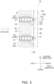
Fig. 3] Fig. 3 is a cross-sectional view of the heat exchanger according to an embodiment of the present disclosure. - [
Fig. 4] Fig. 4 is an enlarged view of a fin constituting the heat exchanger. - [
Fig. 5] Fig. 5 is a diagram for describing a flow of water. - [
Fig. 6] Fig. 6 is an enlarged view of a fin constituting a heat exchanger according to a modification. - [
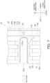
Fig. 7] Fig. 7 is an enlarged view of a fin constituting a heat exchanger according to another modification. - An air-conditioning apparatus including a heat exchanger according to an embodiment of the present disclosure will be described with reference to
Fig. 1 . As illustrated inFig. 1 , an air-conditioning apparatus 200 is an apparatus used for cooling and heating the inside of a room in a building or the like by performing a vapor compression refrigeration cycle operation. - The air-
conditioning apparatus 200 mainly includes anoutdoor unit 220, anindoor unit 230, and a liquid-refrigerant connection pipe 240 and a gas-refrigerant connection pipe 250 that connect theoutdoor unit 220 and theindoor unit 230 to each other. In addition, a vaporcompression refrigerant circuit 210 of the air-conditioning apparatus 200 is configured by connecting theoutdoor unit 220 and theindoor unit 230 via the liquid-refrigerant connection pipe 240 and the gas-refrigerant connection pipe 250. - The
outdoor unit 220 is installed outdoors. Theoutdoor unit 220 mainly includes acompressor 221, a flowpath switching mechanism 222, anoutdoor heat exchanger 223, and anexpansion mechanism 224. - The
compressor 221 is a mechanism that compresses a low-pressure refrigerant in the refrigeration cycle until the pressure of the refrigerant becomes high. - The flow
path switching mechanism 222 is a mechanism that switches the flow direction of a refrigerant when switching between a cooling operation and a heating operation. During the cooling operation, the flowpath switching mechanism 222 connects a discharge side of thecompressor 221 and a gas side of theoutdoor heat exchanger 223, and connects a gas side of an indoor heat exchanger 231 (described later) and a suction side of thecompressor 221 to each other via the gas-refrigerant connection pipe 250 (see solid lines in the flowpath switching mechanism 222 inFig. 1 ). On the other hand, during the heating operation, the flowpath switching mechanism 222 connects the discharge side of thecompressor 221 and the gas side of theindoor heat exchanger 231 to each other via the gas-refrigerant connection pipe 250, and connects the gas side of theoutdoor heat exchanger 223 and the suction side of thecompressor 221 to each other (see broken lines in the flowpath switching mechanism 222 inFig. 1 ). - The
outdoor heat exchanger 223 is a heat exchanger that functions as a radiator for a refrigerant during the cooling operation, and functions as an evaporator for the refrigerant during the heating operation. Theoutdoor heat exchanger 223 has a liquid side connected to theexpansion mechanism 224, and has the gas side connected to the flowpath switching mechanism 222. - The
expansion mechanism 224 is a mechanism that decompresses a high pressure liquid refrigerant that has radiated heat in theoutdoor heat exchanger 223 before the refrigerant is sent to theindoor heat exchanger 231 during the cooling operation, and decompresses a high pressure liquid refrigerant that has radiated heat in theindoor heat exchanger 231 before the refrigerant is sent to theoutdoor heat exchanger 223 during the heating operation. - In addition, the
outdoor unit 220 is provided with anoutdoor fan 225 for sucking outdoor air into theoutdoor unit 220, supplying the outdoor air to theoutdoor heat exchanger 223, and then discharging the outdoor air to the outside of theoutdoor unit 220. - The
indoor unit 230 is installed indoors. Theindoor unit 230 mainly includes theindoor heat exchanger 231 and anindoor fan 232. - The
indoor heat exchanger 231 is a heat exchanger that functions as an evaporator for a refrigerant during the cooling operation, and functions as a radiator for the refrigerant during the heating operation. Theindoor heat exchanger 231 has a liquid side connected to the liquid-refrigerant connection pipe 240, and has the gas side connected to the gas-refrigerant connection pipe 250. - In addition, the
indoor unit 230 is provided with theindoor fan 232 for sucking indoor air into theindoor unit 230, supplying the indoor air to theindoor heat exchanger 231, and then discharging the indoor air to the outside of theindoor unit 230. - In a case where the air-
conditioning apparatus 200 performs the cooling operation, a low-pressure refrigerant in the refrigeration cycle is sucked into thecompressor 221, is compressed until the pressure of the refrigerant becomes high in the refrigeration cycle, and is then discharged. The high-pressure refrigerant discharged from thecompressor 221 is sent to theoutdoor heat exchanger 223 through the flowpath switching mechanism 222. The high-pressure refrigerant sent to theoutdoor heat exchanger 223 exchanges heat with outdoor air supplied by theoutdoor fan 225 and radiates heat in theoutdoor heat exchanger 223. The high-pressure refrigerant that has radiated heat in theoutdoor heat exchanger 223 is sent to theexpansion mechanism 224, and is decompressed until the pressure of the refrigerant becomes low in the refrigeration cycle. The low-pressure refrigerant decompressed in theexpansion mechanism 224 is sent to theindoor heat exchanger 231 through the liquid-refrigerant connection pipe 240. The low-pressure refrigerant sent to theindoor heat exchanger 231 exchanges heat with indoor air supplied by theindoor fan 232 and evaporates in theindoor heat exchanger 231. As a result, the indoor air is cooled and blown into the room. The low-pressure refrigerant that has evaporated in theindoor heat exchanger 231 is sucked again into thecompressor 221 through the gas-refrigerant connection pipe 250 and the flowpath switching mechanism 222. - In a case where the air-
conditioning apparatus 200 performs the heating operation, a low-pressure refrigerant in the refrigeration cycle is sucked into thecompressor 221, is compressed until the pressure of the refrigerant becomes high in the refrigeration cycle, and is then discharged. The high-pressure refrigerant discharged from thecompressor 221 is sent to theindoor heat exchanger 231 through the flowpath switching mechanism 222 and the gas-refrigerant connection pipe 250. The high-pressure refrigerant sent to theindoor heat exchanger 231 exchanges heat with indoor air supplied by theindoor fan 232 and radiates heat in theindoor heat exchanger 231. As a result, the indoor air is heated and blown into the room. The high-pressure refrigerant that has radiated heat in theindoor heat exchanger 231 is sent to theexpansion mechanism 224 through the liquid-refrigerant connection pipe 240, and is decompressed until the pressure of the refrigerant becomes low in the refrigeration cycle. The low-pressure refrigerant decompressed in theexpansion mechanism 224 is sent to theoutdoor heat exchanger 223. The low-pressure refrigerant sent to theoutdoor heat exchanger 223 exchanges heat with outdoor air supplied by theindoor fan 232 and evaporates in theoutdoor heat exchanger 223. The low-pressure refrigerant that has evaporated in theoutdoor heat exchanger 223 is sucked again into thecompressor 221 through the flowpath switching mechanism 222. - A
heat exchanger 10 according to an embodiment of the present disclosure will be described with reference toFigs. 1 to 5 . Theheat exchanger 10 of the present embodiment is included in theindoor unit 230 of the air-conditioning apparatus 200 inFig. 1 . Specifically, theheat exchanger 10 is theindoor heat exchanger 231 illustrated inFig. 1 . - As illustrated in
Figs. 2 to 5 , theheat exchanger 10 includes a plurality offlat tubes 20 and a plurality offins 30. Theflat tubes 20 are arranged in a first direction. Thefins 30 are joined to theflat tubes 20. Theheat exchanger 10 causes heat exchange between a refrigerant that flows inside theflat tubes 20 and air that flows outside theflat tubes 20. Theheat exchanger 10 causes heat exchange between air and the refrigerant without mixing the air and the refrigerant with each other. - Air flows outside the
flat tubes 20 along a second direction that intersects the first direction. Here, the first direction is the up-down (vertical) direction. The second direction is orthogonal to the first direction. Specifically, the second direction is the left-right direction. In addition, as illustrated inFigs. 2 to 5 , air flows in a direction from the left to the right. In other words, the left side is the upstream side of the air flow, and the right side is the downstream side of the air flow. - As illustrated in
Fig. 3 , a plurality of theflat tubes 20 are disposed parallel to each other at an interval along the first direction. As illustrated inFig. 2 , theflat tubes 20 extend in a third direction. The third direction intersects the first direction and the second direction. Here, the third direction is orthogonal to the first direction and the second direction. Specifically, the third direction is the front-rear direction. - As illustrated in
Figs. 2 to 5 , the cross-sectional shape of theflat tube 20 is a flat oval shape or a rectangular shape with rounded corners. The length (width) of theflat tube 20 in the second direction is greater than the length (thickness) of theflat tube 20 in the first direction. Theflat tube 20 is made of, for example, aluminum or an aluminum alloy. - The
flat tube 20 is a heat transfer tube in which a refrigerant flows. Theflat tube 20 is formed with a plurality of throughholes 21 arranged in the second direction. The refrigerant that exchanges heat with air in theheat exchanger 10 passes through the through holes 21. These plurality of through holes extend through theflat tube 20 along the third direction. - The
fins 30 are joined to the plurality offlat tubes 20. Here, theflat tubes 20 and thefins 30 are joined to each other by brazing. Thefins 30 increase the heat transfer area between theflat tubes 20 and air, and enhance heat exchange between the refrigerant and the air. - As illustrated in
Fig. 2 , the plurality offins 30 are disposed parallel to each other at intervals along the third direction. Thefins 30 extend in the first direction. Thefins 30 are disposed so as to intersect (here, orthogonal to) an extending direction of theflat tubes 20. In the present embodiment, the plurality offins 30 are disposed in parallel and at equal intervals. In other words, the plurality offins 30 are arranged in the third direction at a predetermined fin pitch P. In the present embodiment, the fin pitch P is greater than or equal to 1.2 mm and less than or equal to 1.4 mm. - The
fin 30 has a flat plate shape. Thefin 30 is formed by press working or the like. Thefin 30 is made of, for example, aluminum or an aluminum alloy. - As illustrated in
Figs. 3 to 5 , thefin 30 is formed with a plurality ofinsertion portions 31 for inserting theflat tubes 20. Theinsertion portion 31 is notched in the second direction from an air flowupstream end 30a toward an air flowdownstream end 30b side. The plurality ofinsertion portions 31 are arranged at intervals along the first direction. - The
fin 30 includes a firstjoint portion 32, afirst plate portion 33, a secondjoint portion 34, asecond plate portion 35, and athird plate portion 36. Hereinafter, inFig. 3 , theflat tube 20 positioned on the upper side will be described as a firstflat tube 20a, and theflat tube 20 positioned on the lower side will be described as a secondflat tube 20b. The firstflat tube 20a and the secondflat tube 20b are disposed adjacent to each other in the first direction. - As illustrated in
Fig. 3 , the firstjoint portion 32 is joined to the firstflat tube 20a. Here, the firstjoint portion 32 has a U shape as viewed in cross section. In the present embodiment, the firstjoint portion 32 is a collar portion. Specifically, the firstjoint portion 32 extends so as to protrude in the third direction from theinsertion portion 31 on one surface (front surface) side of thefin 30 toward the other surface (rear surface) of anadjacent fin 30. - The
first plate portion 33 is positioned between an air flowdownstream end 30b and the firstjoint portion 32. Thefirst plate portion 33 is continuous with the firstjoint portion 32. Thefirst plate portion 33 is formed with a first protrudingportion 133 and arib 134. - The first protruding
portion 133 causes water to flow in the first direction in the vicinity of the firstflat tube 20a. In other words, the first protrudingportion 133 is a water-guiding rib that causes water located in the vicinity of the firstflat tube 20a to flow in the first direction. - As illustrated in
Fig. 4 , a distance L1 in the second direction between an air flowdownstream end 120a of the firstflat tube 20a and the first protrudingportion 133 is less than a distance L2 in the second direction between the air flowdownstream end 30b of thefin 30 and the first protrudingportion 133. The distance L1 is preferably 1/3 or less of the distance L2, and more preferably 1/5 or less of the distance L2. - The first protruding
portion 133 extends in the first direction. InFigs. 3 to 5 , the first protrudingportion 133 extends in the up-down direction. In the present embodiment, the first protrudingportion 133 extends in the gravity (vertical) direction. With such a configuration, in the present embodiment, the first protrudingportion 133 causes water to flow downward by the weight of the water in the vicinity of the downstream side of the firstjoint portion 32 joined to the firstflat tube 20a. - The height of the first protruding
portion 133 is not limited, but is greater than or equal to 0.1 mm and less than or equal to 0.6 mm, for example. Note that the height is a protruding distance (distance in the third direction) from one surface of thefin 30 toward the other surface of theadjacent fin 30. - The
rib 134 is a rib for enhancing heat transfer. Therib 134 protrudes from one surface of thefin 30 toward the other surface of theadjacent fin 30. Therib 134 has a rectangular shape as viewed in cross section. InFigs. 3 to 5 , the length (width) of therib 134 in the second direction is greater than the length (width) of the first protrudingportion 133 in the second direction. - The second
joint portion 34 is joined to the secondflat tube 20b. The secondjoint portion 34 has the same shape as the firstjoint portion 32. - The
second plate portion 35 is positioned between the firstjoint portion 32 and the secondjoint portion 34. Thesecond plate portion 35 is continuous with the firstjoint portion 32 and the secondjoint portion 34. Thesecond plate portion 35 is formed with a second protrudingportion 135 andnotches 37. - The second protruding
portion 135 extends in a direction inclined with respect to the first direction and the second direction. InFigs. 3 to 5 , the second protrudingportion 135 extends from an upper end portion of thesecond plate portion 35 toward the lower right. The second protrudingportion 135 is a water-guiding rib that drains water between the firstflat tube 20a and the secondflat tube 20b. - In the present embodiment, the second protruding
portion 135 extends obliquely downward from the vicinity of an air flow downstream portion of the firstflat tube 20a. Specifically, the second protrudingportion 135 extends from the vicinity of thedownstream end 120a toward the downstream side of the air flow so as to be connected to a third protrudingportion 136. With such a configuration, the second protrudingportion 135 provided here is a water-guiding rib that drains water located in the vicinity of the air flow downstream portion of the firstflat tube 20a between the firstflat tube 20a and the secondflat tube 20b toward the lower right. - As illustrated in
Fig. 4 , a distance L3 in the second direction between the air flowdownstream end 120a of the firstflat tube 20a and one end (left end inFig. 4 ) of the second protrudingportion 135 in the second direction is less than a distance L4 in the second direction between the air flowupstream end 30a of thefin 30 and one end (left end inFig. 4 ) of the second protrudingportion 135 in the second direction. The distance L3 is preferably 1/3 or less of the distance L4, and more preferably 1/5 or less of the distance L4. - The height of the second protruding
portion 135 may be equal to, less than, or greater than the height of the first protrudingportion 133. Here, the height of the second protrudingportion 135 is, for example, greater than or equal to 0.1 mm and less than or equal to 0.6 mm. - The
notches 37 are thenotches 37 for enhancing heat transfer. A plurality of (three inFig. 3 )notches 37 are arranged in the second direction. In addition, thenotch 37 extends in the first direction. Here, thenotch 37 is recessed from the other surface of thefin 30 toward one surface of anadjacent fin 30. - The
third plate portion 36 is positioned between the air flowdownstream end 30b and thesecond plate portion 35. Thethird plate portion 36 is continuous with thefirst plate portion 33 and thesecond plate portion 35. - The
third plate portion 36 is formed with the third protrudingportion 136 that is continuous with the first protrudingportion 133. The thirdprotruding portion 136 is a water-guiding rib that causes water from the first protrudingportion 133 to flow in the first direction. - The third
protruding portion 136 extends in the first direction. InFigs. 3 to 5 , the third protrudingportion 136 extends in the up-down direction. In the present embodiment, the third protrudingportion 136 extends in the gravity (vertical) direction. With such a configuration, in the present embodiment, the third protrudingportion 136 causes water from the first protrudingportion 133 to flow downward. - The position of the third protruding
portion 136 in the second direction is the same as that of the first protrudingportion 133. In other words, the first protrudingportion 133 and the third protrudingportion 136 are linearly continuous in the up-down (vertical) direction. - The height of the third protruding
portion 136 may be equal to, less than, or greater than the height of the first protrudingportion 133. Here, the height of the third protrudingportion 136 is the same as that of the first protrudingportion 133. - Note that, in the present embodiment, the
fin 30 does not have a shape that hinders the guiding of water by the first protrudingportion 133, the second protrudingportion 135, and the third protrudingportion 136. - In addition,
Fig. 3 illustrates an area in which thefin 30 is joined to the firstflat tube 20a and the secondflat tube 20b, but as illustrated inFig. 2 , in the present embodiment, thefin 30 is joined to three or moreflat tubes 20. Furthermore, the linear rib formed by the continuity of the first protrudingportion 133 and the third protrudingportion 136 extends from the upper end portion to the lower end portion of thefin 30. - During the operation such as the cooling operation and the heating operation of the air-
conditioning apparatus 200 illustrated inFig. 1 , a refrigerant is sent to theflat tubes 20 of theheat exchanger 10 that serves as theindoor heat exchanger 231 in therefrigerant circuit 210. The refrigerant flows through the plurality of throughholes 21 of theflat tubes 20. Then, the refrigerant that flows inside theflat tubes 20 exchanges heat with indoor air that flows outside theflat tubes 20. During this operation, condensation water may be generated around the joint portions of thefins 30 joined to theflat tubes 20. - As illustrated in
Fig. 5 , water W as condensation water that is accumulated on an upper portion of the firstflat tube 20a moves along the firstjoint portion 32. Specifically, the water W moves in an arc shape along a curved portion of the first protrudingportion 133. - In addition, the water moved along the first protruding
portion 133 and water W accumulated on a lower portion of the firstflat tube 20a move in a direction inclined with respect to the first direction and the second direction (toward the lower right side inFig. 5 ) along the second protrudingportion 135. - Then, the water W moves in the first direction (downward in
Fig. 5 ) along the third protrudingportion 136 that is connected to the second protrudingportion 135 and is continuous with the first protrudingportion 133. - In this manner, the water W generated around the first
flat tube 20a is directly drawn into the first protrudingportion 133 and the second protrudingportion 135, and is drained downward along the third protrudingportion 136. In other words, the water W is drained downward by flowing along the first protrudingportion 133, the second protrudingportion 135, and the third protrudingportion 136. This prevents the water W generated around the firstflat tube 20a from getting caught at any point along the way, and increases the drainage rate. - Note that, in some cases, depending on the amount of the water W, the heights of the first protruding
portion 133, the second protrudingportion 135, and the third protrudingportion 136, and the like, the water W may flow on the left side of the first protrudingportion 133 and the third protrudingportion 136 inFig. 5 . For example, in a case where the height of the second protrudingportion 135 is greater than the heights of the first protrudingportion 133 and the third protrudingportion 136, the water W mainly flows on the right side of the first protrudingportion 133 and the third protrudingportion 136. On the other hand, in a case where the height of the second protrudingportion 135 is less than or equal to the heights of the first protrudingportion 133 and the third protrudingportion 136, the water W mainly flows on the left side of the first protrudingportion 133 and the third protrudingportion 136. - (3-1)
Theheat exchanger 10 according to the present embodiment includes a plurality offlat tubes 20 and one ormore fins 30. Theflat tubes 20 are arranged in the first direction. Thefins 30 are joined to theflat tubes 20. Theheat exchanger 10 causes heat exchange between a refrigerant that flows inside theflat tubes 20 and air that flows outside theflat tubes 20 along the second direction that intersects the first direction. Thefin 30 includes the firstjoint portion 32 and thefirst plate portion 33. The firstjoint portion 32 is joined to the firstflat tube 20a. Thefirst plate portion 33 is positioned between the air flowdownstream end 30b and the firstjoint portion 32. Thefirst plate portion 33 is formed with the first protrudingportion 133 for causing water to flow in the first direction in the vicinity of the firstflat tube 20a. - In the
heat exchanger 10 of the present embodiment, the first protrudingportion 133 can cause the water W located in the vicinity of the firstflat tube 20a to flow in the first direction. This can reduce the time required to drain, in the first direction, the water that is on thefin 30 and is in the vicinity of the firstflat tube 20a. - In addition, in the present embodiment, the
heat exchanger 10 drains water generated around the firstflat tube 20a using the first protrudingportion 133 in the vicinity of the firstflat tube 20a without transporting the water to the air flowdownstream end 30b of thefin 30. Therefore, splashing of water from thefin 30 can be suppressed. - (3-2)
In theheat exchanger 10 of the present embodiment, the first protrudingportion 133 extends in the first direction. With such a configuration, the water W can be transported along the first protrudingportion 133. This can further reduce the time required to drain, in the first direction, the water W that is on thefin 30 and is in the vicinity of the firstflat tube 20a. - (3-3)
In theheat exchanger 10 of the present embodiment, the distance L1 in the second direction between the air flowdownstream end 120a of the firstflat tube 20a and the first protrudingportion 133 is less than the distance L2 in the second direction between the air flowdownstream end 30b of thefin 30 and the first protrudingportion 133. - With such a configuration, in the
first plate portion 33, the first protrudingportion 133 is disposed near the firstflat tube 20a and on the upstream side of the air flow. Therefore, splashing of water from theheat exchanger 10 can be further suppressed. - (3-4)
In theheat exchanger 10 of the present embodiment, thefin 30 further includes the secondjoint portion 34 and thesecond plate portion 35. The secondjoint portion 34 is joined to the secondflat tube 20b that is disposed adjacent to the firstflat tube 20a in the first direction. Thesecond plate portion 35 is positioned between the firstjoint portion 32 and the secondjoint portion 34. Thesecond plate portion 35 is formed with the second protrudingportion 135 extending in the direction inclined with respect to the first direction and the second direction. - Here, the second protruding
portion 135 can drain the water W between the firstflat tube 20a and the secondflat tube 20b. - (3-5)
In theheat exchanger 10 of the present embodiment, the first protrudingportion 133 extends in the up-down direction. The second protrudingportion 135 extends obliquely downward from the vicinity of the air flow downstream portion of the firstflat tube 20a. - Here, the second protruding
portion 135 can cause the water W below and on the downstream side of the firstflat tube 20a to flow downward. - (3-6)
In theheat exchanger 10 of the present embodiment, thefin 30 further includes the secondjoint portion 34, thesecond plate portion 35, and thethird plate portion 36. The secondjoint portion 34 is joined to the secondflat tube 20b that is disposed adjacent to the firstflat tube 20a in the first direction. Thesecond plate portion 35 is positioned between the firstjoint portion 32 and the secondjoint portion 34. Thethird plate portion 36 is positioned between the air flowdownstream end 30b and thesecond plate portion 35. Thethird plate portion 36 is formed with the third protrudingportion 136 that is continuous with the first protrudingportion 133. - Here, the first protruding
portion 133 and the third protrudingportion 136 can cause the water W located in the vicinity of the firstflat tube 20a to flow in the first direction to the secondflat tube 20b. - In addition, the second protruding
portion 135 can guide the water W below and on the downstream side of the firstflat tube 20a to the third protrudingportion 136, and the third protrudingportion 136 can cause the water W to flow further downward. - (3-7)
In theheat exchanger 10 of the present embodiment, thefin 30 further includes the secondjoint portion 34 and thesecond plate portion 35. The secondjoint portion 34 is joined to the secondflat tube 20b that is disposed adjacent to the firstflat tube 20a in the first direction. Thesecond plate portion 35 is positioned between the firstjoint portion 32 and the secondjoint portion 34. Thesecond plate portion 35 is formed with thenotches 37 for enhancing heat transfer. - Here, the
notches 37 can enhance heat transfer between air and thefin 30. This can enhance heat exchange between the refrigerant that flows inside theflat tubes 20 and air that flows outside thefins 30. - (3-8)
In theheat exchanger 10 of the present embodiment, the plurality offins 30 are arranged in the extending direction of theflat tubes 20. The fin pitch P of thefins 30 is greater than or equal to 1.2 mm and less than or equal to 1.4 mm. The height of the first protrudingportion 133 is greater than or equal to 0.1 mm and less than or equal to 0.6 mm. - With such a configuration, in the
heat exchanger 10 where the plurality offins 30 are stacked, the first protrudingportion 133 can easily realize a reduction in the time required to drain water in the first direction. - (3-9)
Theheat exchanger 10 of the present embodiment is included in theindoor unit 230 of the air-conditioning apparatus 200. In other words, theheat exchanger 10 of the present embodiment can be applied to theindoor unit 230 of the air-conditioning apparatus 200. Theheat exchanger 10 of the present embodiment can reduce the time required to drain water and can suppress the splashing of the water from thefin 30. Therefore, theheat exchanger 10 is suitably used for theindoor heat exchanger 231 disposed indoors. - In the above-described embodiment, the second protruding
portion 135 extends obliquely downward from the vicinity of the air flow downstream portion of the firstflat tube 20a, but the present invention is not limited thereto. In aheat exchanger 11 of the present modification, as illustrated inFig. 6 , the second protrudingportion 135 extends obliquely downward from the vicinity of an air flowupstream portion 120b of the firstflat tube 20a. Here, the second protrudingportion 135 extends from the vicinity of an air flow upstream end of the firstjoint portion 32 toward the lower right. - As illustrated in
Fig. 6 , a distance in the second direction between the air flowdownstream end 120a of the firstflat tube 20a and one end (left end inFig. 6 ) of the second protrudingportion 135 in the second direction is greater than a distance in the second direction between the air flowupstream end 30a of thefin 30 and one end (left end inFig. 6 ) of the second protrudingportion 135 in the second direction. - In the present modification, the water W accumulated on the lower portion of the first
flat tube 20a moves from the upstream side of the air flow in the direction inclined with respect to the first direction and the second direction (toward the lower right side inFig. 6 ) along the second protrudingportion 135. Then, the water W moves in the first direction (downward inFig. 6 ) along the third protrudingportion 136 that is connected to the second protrudingportion 135. - As described above, in the
heat exchanger 11 of the present modification, the first protrudingportion 133 extends in the up-down (vertical) direction. The second protrudingportion 135 extends obliquely downward from the vicinity of the air flowupstream portion 120b of the firstflat tube 20a. - Here, the second protruding
portion 135 can cause the water W below and on the upstream side of the firstflat tube 20a to flow downward. - In the above-described embodiment, the first protruding
portion 133 and the third protrudingportion 136 are formed as water-guiding ribs for causing water to flow in the first direction, but another water-guiding rib may be further formed. As illustrated inFig. 7 , aheat exchanger 12 of the present modification is further formed with a fourth protrudingportion 138 for causing water to flow in the first direction. The fourth protrudingportion 138 is formed on the downstream side of the first protrudingportion 133 and the third protrudingportion 136 in the air flow. - Specifically, the fourth protruding
portion 138 is formed in the vicinity of the air flowdownstream end 30b of thefin 30 so as to extend in the first direction. The fourth protrudingportion 138 continuously extends from the upper end portion to the lower end portion of thefin 30. The fourth protrudingportion 138 is parallel and liner to the first protrudingportion 133 and the third protrudingportion 136. - In the above-described embodiment, the
fin 30 is formed with thenotches 37,ribs 134, and the like for enhancing heat transfer, but the present invention is not limited thereto. Notches, ribs, and the like for enhancing heat transfer are formed as appropriate. In the present modification, ribs for enhancing heat transfer are further formed on both sides of the third protrudingportion 136. The ribs formed on both sides are, for example, L-shaped as viewed in cross section. - In the above-described embodiment, the
heat exchanger 10 is applied to theindoor heat exchanger 231, but the present invention is not limited thereto. In the present modification, theheat exchanger 10 is applied to theoutdoor heat exchanger 223. - In the above-described embodiment, the
heat exchanger 10 is applied to the air-conditioning apparatus 200, but the present invention is not limited thereto. Theheat exchanger 10 may be applied to a hot water supply apparatus, a floor heating apparatus, and a refrigeration apparatus such as a refrigerating device. - The embodiment of the present disclosure has been described heretofore, and it will be understood that a variety of modifications in mode and detail may be made without departing from the gist and scope of the present disclosure as set forth in claims.
-
- 1 AIR-CONDITIONING APPARATUS
- 10, 11, 12 HEAT EXCHANGER
- 20, 20a, 20b FLAT TUBE
- 30 FIN
- 30b, 120a DOWNSTREAM END
- 32 FIRST JOINT PORTION
- 33 FIRST PLATE PORTION
- 34 SECOND JOINT PORTION
- 35 SECOND PLATE PORTION
- 36 THIRD PLATE PORTION
- 37 NOTCH
- 133 FIRST PROTRUDING PORTION
- 135 SECOND PROTRUDING PORTION
- 136 THIRD PROTRUDING PORTION
- 200 AIR-CONDITIONING APPARATUS
- 210 REFRIGERANT CIRCUIT
- 230 INDOOR UNIT
- PTL 1: International Publication No.
2018/003123
Claims (10)
- A heat exchanger (10), comprising:a plurality of flat tubes (20) arranged in a first direction; anda fin (30) joined to the flat tubes, andthe heat exchanger causing heat exchange between a refrigerant that flows inside the flat tube and air that flows outside the flat tube along a second direction that intersects the first direction, whereinthe fin includes:a first joint portion (32) joined to a first flat tube included in the flat tubes; anda first plate portion (33) positioned between an air flow downstream end and the first joint portion, andthe first plate portion is formed with a first protruding portion (133) for causing water to flow in the first direction in a vicinity of the first flat tube.
- The heat exchanger according to claim 1, wherein the first protruding portion extends in the first direction.
- The heat exchanger according to claim 1 or 2, wherein a distance (L1) in the second direction between an air flow downstream end (120a) of the first flat tube and the first protruding portion is less than a distance (L2) in the second direction between the air flow downstream end (30b) of the fin and the first protruding portion.
- The heat exchanger according to any one of claims 1 to 3, wherein
the fin further includes:a second joint portion (34) joined to a second flat tube that is included in the flat tubes and is disposed adjacent to the first flat tube in the first direction; anda second plate portion (35) positioned between the first joint portion and the second joint portion, andthe second plate portion is formed with a second protruding portion (135) extending in a direction inclined with respect to the first direction and the second direction. - The heat exchanger according to claim 4, whereinthe first protruding portion extends in an up-down direction, andthe second protruding portion extends obliquely downward from a vicinity of an air flow downstream portion of the first flat tube.
- The heat exchanger according to claim 4, whereinthe first protruding portion extends in an up-down direction, andthe second protruding portion extends obliquely downward from a vicinity of an air flow upstream portion of the first flat tube.
- The heat exchanger according to any one of claims 1 to 6, wherein
the fin further includes:a second joint portion (34) joined to a second flat tube that is included in the flat tubes and is disposed adjacent to the first flat tube in the first direction;a second plate portion (35) positioned between the first joint portion and the second joint portion; anda third plate portion (36) positioned between the air flow downstream end and the second plate portion, andthe third plate portion is formed with a third protruding portion (136) that is continuous with the first protruding portion. - The heat exchanger according to any one of claims 1 to 7, wherein
the fin further includes:a second joint portion (34) joined to a second flat tube that is included in the flat tubes and is disposed adjacent to the first flat tube in the first direction; anda second plate portion (35) positioned between the first joint portion and the second joint portion, andthe second plate portion is formed with a notch (37) for enhancing heat transfer. - The heat exchanger according to any one of claims 1 to 8, whereina plurality of the fins are arranged in an extending direction of the flat tube, anda fin pitch (P) of the fins is greater than or equal to 1.2 mm and less than or equal to 1.4 mm, anda height of the first protruding portion is greater than or equal to 0.1 mm and less than or equal to 0.6 mm.
- The heat exchanger according to any one of claims 1 to 9, wherein the heat exchanger is included in an indoor unit (230) of an air-conditioning apparatus (200).
Applications Claiming Priority (2)
| Application Number | Priority Date | Filing Date | Title |
|---|---|---|---|
| JP2022114818A JP7530003B2 (en) | 2022-07-19 | 2022-07-19 | Heat exchanger |
| PCT/JP2023/025837 WO2024018983A1 (en) | 2022-07-19 | 2023-07-13 | Heat exchanger |
Publications (3)
| Publication Number | Publication Date |
|---|---|
| EP4560246A1 true EP4560246A1 (en) | 2025-05-28 |
| EP4560246A8 EP4560246A8 (en) | 2025-07-09 |
| EP4560246A4 EP4560246A4 (en) | 2025-10-15 |
Family
ID=89617839
Family Applications (1)
| Application Number | Title | Priority Date | Filing Date |
|---|---|---|---|
| EP23842906.2A Pending EP4560246A4 (en) | 2022-07-19 | 2023-07-13 | Heat exchanger |
Country Status (5)
| Country | Link |
|---|---|
| US (1) | US20250146766A1 (en) |
| EP (1) | EP4560246A4 (en) |
| JP (1) | JP7530003B2 (en) |
| CN (1) | CN119497812A (en) |
| WO (1) | WO2024018983A1 (en) |
Family Cites Families (14)
| Publication number | Priority date | Publication date | Assignee | Title |
|---|---|---|---|---|
| JPS58180U (en) * | 1981-06-18 | 1983-01-05 | 松下電器産業株式会社 | Tube heat exchanger with fins |
| JPH0590173U (en) * | 1992-04-20 | 1993-12-07 | 住友軽金属工業株式会社 | Fin tube heat exchanger |
| JP2006153327A (en) * | 2004-11-26 | 2006-06-15 | Daikin Ind Ltd | Heat exchanger |
| KR101521371B1 (en) * | 2011-01-21 | 2015-05-19 | 다이킨 고교 가부시키가이샤 | Heat exchanger and air conditioner |
| KR101313347B1 (en) * | 2011-01-21 | 2013-10-01 | 다이킨 고교 가부시키가이샤 | Heat exchanger and air conditioner |
| EP2725311B1 (en) * | 2012-10-29 | 2018-05-09 | Samsung Electronics Co., Ltd. | Heat exchanger |
| EP3306251B1 (en) * | 2015-05-29 | 2022-07-13 | Mitsubishi Electric Corporation | Heat exchanger |
| JP6380449B2 (en) * | 2016-04-07 | 2018-08-29 | ダイキン工業株式会社 | Indoor heat exchanger |
| WO2017208493A1 (en) | 2016-06-03 | 2017-12-07 | 日立ジョンソンコントロールズ空調株式会社 | Air conditioner |
| WO2018003123A1 (en) | 2016-07-01 | 2018-01-04 | 三菱電機株式会社 | Heat exchanger and refrigeration cycle apparatus |
| CN106288911B (en) | 2016-09-07 | 2018-08-14 | 珠海格力电器股份有限公司 | Fin and radiator comprising same |
| WO2018073898A1 (en) | 2016-10-18 | 2018-04-26 | 三菱電機株式会社 | Heat exchanger, outdoor unit, and manufacturing device and manufacturing method for heat exchanger |
| JP6466631B1 (en) * | 2018-03-13 | 2019-02-06 | 日立ジョンソンコントロールズ空調株式会社 | Heat exchanger and air conditioner equipped with the same |
| JP7752953B2 (en) | 2021-03-24 | 2025-10-14 | 日本キヤリア株式会社 | heat exchanger |
-
2022
- 2022-07-19 JP JP2022114818A patent/JP7530003B2/en active Active
-
2023
- 2023-07-13 EP EP23842906.2A patent/EP4560246A4/en active Pending
- 2023-07-13 WO PCT/JP2023/025837 patent/WO2024018983A1/en not_active Ceased
- 2023-07-13 CN CN202380052356.7A patent/CN119497812A/en active Pending
-
2025
- 2025-01-07 US US19/011,902 patent/US20250146766A1/en active Pending
Also Published As
| Publication number | Publication date |
|---|---|
| JP2024012956A (en) | 2024-01-31 |
| EP4560246A4 (en) | 2025-10-15 |
| WO2024018983A1 (en) | 2024-01-25 |
| CN119497812A (en) | 2025-02-21 |
| JP7530003B2 (en) | 2024-08-07 |
| US20250146766A1 (en) | 2025-05-08 |
| EP4560246A8 (en) | 2025-07-09 |
Similar Documents
| Publication | Publication Date | Title |
|---|---|---|
| US10267527B2 (en) | Outdoor unit for an air-conditioning device | |
| EP3306252A1 (en) | Heat exchanger and refrigeration cycle apparatus | |
| CN104011471B (en) | air conditioner | |
| EP3128263B1 (en) | Heat exchanger and air conditioner | |
| EP3650798B1 (en) | Heat exchanger | |
| US20110120177A1 (en) | Heat exchanger for shedding water | |
| JPWO2018225252A1 (en) | Heat exchanger and refrigeration cycle device | |
| US20170292720A1 (en) | Indoor unit for air-conditioning apparatus | |
| JP6318371B2 (en) | Outdoor unit and refrigeration cycle apparatus using the same | |
| US20250146766A1 (en) | Heat exchanger | |
| JP6415597B2 (en) | Refrigeration cycle equipment | |
| US7673468B2 (en) | High efficiency evaporatively cooled condenser | |
| EP3825628A1 (en) | Refrigeration cycle device | |
| WO2020070869A1 (en) | Heat exchanger and refrigeration cycle device | |
| CN113544458B (en) | Gas header, heat exchanger, and refrigeration cycle device | |
| US11384970B2 (en) | Heat exchanger and refrigeration cycle apparatus | |
| US20220099312A1 (en) | Heat exchanger and air conditioning apparatus | |
| EP4571233A1 (en) | Heat exchanger | |
| KR100829185B1 (en) | Air conditioner | |
| JP7436895B1 (en) | Heat exchanger | |
| JP2015227754A (en) | Heat exchanger | |
| US20240255199A1 (en) | Air conditioner | |
| EP3467391A1 (en) | Outdoor unit for air conditioning device | |
| EP4006474A1 (en) | Heat exchanger and refrigeration cycle device | |
| JPH11325642A (en) | Air conditioner |
Legal Events
| Date | Code | Title | Description |
|---|---|---|---|
| STAA | Information on the status of an ep patent application or granted ep patent |
Free format text: STATUS: THE INTERNATIONAL PUBLICATION HAS BEEN MADE |
|
| PUAI | Public reference made under article 153(3) epc to a published international application that has entered the european phase |
Free format text: ORIGINAL CODE: 0009012 |
|
| STAA | Information on the status of an ep patent application or granted ep patent |
Free format text: STATUS: REQUEST FOR EXAMINATION WAS MADE |
|
| 17P | Request for examination filed |
Effective date: 20250205 |
|
| AK | Designated contracting states |
Kind code of ref document: A1 Designated state(s): AL AT BE BG CH CY CZ DE DK EE ES FI FR GB GR HR HU IE IS IT LI LT LU LV MC ME MK MT NL NO PL PT RO RS SE SI SK SM TR |
|
| RIN1 | Information on inventor provided before grant (corrected) |
Inventor name: UCHIDA, KENGO Inventor name: ZHENG, CHEN Inventor name: ANDOU, TOORU Inventor name: HIROKAWA, TOMOKI Inventor name: SATOU, KEN Inventor name: OKUNO, AYA |
|
| P01 | Opt-out of the competence of the unified patent court (upc) registered |
Free format text: CASE NUMBER: UPC_APP_3796_4560246/2025 Effective date: 20250820 |
|
| A4 | Supplementary search report drawn up and despatched |
Effective date: 20250916 |
|
| RIC1 | Information provided on ipc code assigned before grant |
Ipc: F28F 1/32 20060101AFI20250910BHEP Ipc: F28F 17/00 20060101ALI20250910BHEP |
|
| DAV | Request for validation of the european patent (deleted) | ||
| DAX | Request for extension of the european patent (deleted) | ||
| STAA | Information on the status of an ep patent application or granted ep patent |
Free format text: STATUS: THE APPLICATION IS DEEMED TO BE WITHDRAWN |