EP4560165A1 - Gearshift lever assembly with magnetic feeling for a motor vehicle - Google Patents
Gearshift lever assembly with magnetic feeling for a motor vehicle Download PDFInfo
- Publication number
- EP4560165A1 EP4560165A1 EP24213929.3A EP24213929A EP4560165A1 EP 4560165 A1 EP4560165 A1 EP 4560165A1 EP 24213929 A EP24213929 A EP 24213929A EP 4560165 A1 EP4560165 A1 EP 4560165A1
- Authority
- EP
- European Patent Office
- Prior art keywords
- magnet
- pole
- lever body
- path
- magnetic
- Prior art date
- Legal status (The legal status is an assumption and is not a legal conclusion. Google has not performed a legal analysis and makes no representation as to the accuracy of the status listed.)
- Pending
Links
Images




Classifications
-
- F—MECHANICAL ENGINEERING; LIGHTING; HEATING; WEAPONS; BLASTING
- F16—ENGINEERING ELEMENTS AND UNITS; GENERAL MEASURES FOR PRODUCING AND MAINTAINING EFFECTIVE FUNCTIONING OF MACHINES OR INSTALLATIONS; THERMAL INSULATION IN GENERAL
- F16H—GEARING
- F16H59/00—Control inputs to control units of change-speed- or reversing-gearings for conveying rotary motion
- F16H59/02—Selector apparatus
- F16H59/08—Range selector apparatus
-
- F—MECHANICAL ENGINEERING; LIGHTING; HEATING; WEAPONS; BLASTING
- F16—ENGINEERING ELEMENTS AND UNITS; GENERAL MEASURES FOR PRODUCING AND MAINTAINING EFFECTIVE FUNCTIONING OF MACHINES OR INSTALLATIONS; THERMAL INSULATION IN GENERAL
- F16H—GEARING
- F16H59/00—Control inputs to control units of change-speed- or reversing-gearings for conveying rotary motion
- F16H59/02—Selector apparatus
- F16H59/08—Range selector apparatus
- F16H59/10—Range selector apparatus comprising levers
-
- G—PHYSICS
- G05—CONTROLLING; REGULATING
- G05G—CONTROL DEVICES OR SYSTEMS INSOFAR AS CHARACTERISED BY MECHANICAL FEATURES ONLY
- G05G5/00—Means for preventing, limiting or returning the movements of parts of a control mechanism, e.g. locking controlling member
- G05G5/06—Means for preventing, limiting or returning the movements of parts of a control mechanism, e.g. locking controlling member for holding members in one or a limited number of definite positions only
-
- F—MECHANICAL ENGINEERING; LIGHTING; HEATING; WEAPONS; BLASTING
- F16—ENGINEERING ELEMENTS AND UNITS; GENERAL MEASURES FOR PRODUCING AND MAINTAINING EFFECTIVE FUNCTIONING OF MACHINES OR INSTALLATIONS; THERMAL INSULATION IN GENERAL
- F16H—GEARING
- F16H59/00—Control inputs to control units of change-speed- or reversing-gearings for conveying rotary motion
- F16H59/02—Selector apparatus
- F16H59/08—Range selector apparatus
- F16H2059/081—Range selector apparatus using knops or discs for rotary range selection
-
- F—MECHANICAL ENGINEERING; LIGHTING; HEATING; WEAPONS; BLASTING
- F16—ENGINEERING ELEMENTS AND UNITS; GENERAL MEASURES FOR PRODUCING AND MAINTAINING EFFECTIVE FUNCTIONING OF MACHINES OR INSTALLATIONS; THERMAL INSULATION IN GENERAL
- F16H—GEARING
- F16H61/00—Control functions within control units of change-speed- or reversing-gearings for conveying rotary motion ; Control of exclusively fluid gearing, friction gearing, gearings with endless flexible members or other particular types of gearing
- F16H61/24—Providing feel, e.g. to enable selection
-
- G—PHYSICS
- G05—CONTROLLING; REGULATING
- G05G—CONTROL DEVICES OR SYSTEMS INSOFAR AS CHARACTERISED BY MECHANICAL FEATURES ONLY
- G05G2505/00—Means for preventing, limiting or returning the movements of parts of a control mechanism, e.g. locking controlling member
Definitions
- the invention relates to a gearshift lever assembly for a motor vehicle, in particular for controlling a manual or automatic transmission of the motor vehicle.
- a motor vehicle generally has a gearshift lever to control a transmission, which could be, more specifically, a manual, automatic or semi-automatic transmission.
- the transmission and the relative gearshift lever are also present in fully electric motor vehicles, as well as in hybrid motor vehicles and motor vehicle exclusively having a heat engine.
- the transmission of fully electric motor vehicles is not normally mechanically connected to the lever, but the position of the latter is determined by means of sensors, whose signals permit an electronic control of the transmission.
- the transmission could be of any type, including a continuously variable transmission (CVT) that can change through a continuous range of gear ratios, or it can even be incorporated in an electric motor of the motor vehicle or be defined by the electric motor itself.
- CVT continuously variable transmission
- the gearshift lever has a plurality of predetermined positions corresponding to respective gears (including the reverse gear) or to operating states, such as a neutral state or a park state, as it is known for automatic transmissions.
- the lever In the predetermined positions, the lever should conveniently be stable; in other words, a driver of the motor vehicle should exceed at least a minimum effort threshold to move the lever from one position in order to move it to another position.
- the driver first receives a feeling of resistance to removing the lever from its current position, immediately followed by a feeling of release or liberation when the lever leaves the current position.
- the driver receives a feeling of engagement when the lever reaches the other desired position.
- gearshift levers need to be improved, specifically in terms of a reduced noise associated with the movements of the lever and of a greater pleasantness of the feelings received, with particular reference to the overall fluidity of the movements of the lever.
- the object of the invention is to fulfil at least one of the needs discussed above, preferably in a simple and repeatable fashion.
- reference number 1 is used to indicate, as a whole, a motor vehicle.
- the motor vehicle 1 could have any type of propulsion apparatus with any type of powertrain, for example an internal combustion engine, an electric motor or other known types of powertrain assemblies.
- the motor vehicle 1 has a plurality of wheels 2 that allow it to be used. In order to cause the rotation of the wheels 2, the motor vehicle 1 also has a transmission, for example of a known type and not shown herein, which transmits the output motion generated by the engine to the wheels 2.
- the transmission sets a gear ratio, namely a ratio of the respective speeds, between the engine and the wheels 2.
- the transmission could comprise a gearbox with a plurality of gears that can be selected to vary the gear ratio.
- the gearbox can be controlled to vary the gear ratio, for example by selectively engaging the gears.
- the gearbox could have a limited number of gears or even have a substantially infinite number of gears, thus defining a continuously variable transmission (CVT).
- CVT continuously variable transmission
- the gearbox could also be absent, whereby the gear ratio could be fixed rather than variable.
- the rotation speed of the wheels 2 would be determined by the engine, which could still be controllable in speed.
- the motor vehicle 1 also has a passenger compartment 3 to accommodate a driver ( figure 2 ).
- the motor vehicle 1 Inside the passenger compartment 3, the motor vehicle 1 comprises a gearshift lever assembly 4.
- the gearshift lever assembly 4 is configured to allow the driver to control or select a state of the transmission of motion from the engine to the wheels 2, in particular by means of the transmission.
- the gearshift lever assembly 4 is configured to control a control unit of the motor vehicle 1, which, in turn, controls the state of the transmission of motion in a consequent manner, namely in a manner consequent to the selection made by the driver by means of the gearshift lever assembly 4.
- the gearbox of the transmission is of an automatic type, whereby the control unit adjusts the gear ratio, for example by selecting the engagement of a specific gear or by controlling a continuously variable transmission, based on the operation of the engine.
- control unit extracts information on the operation of the engine from specific transducers coupled to the control unit and configured to monitor the operation of the engine.
- the state of the transmission of motion could be selected by means of the gearshift lever assembly 4, for example from a park state P, a reverse state R, a neutral state N and a drive state D.
- each gear would define a respective state of transmission of motion, in addition to the aforementioned reverse and neutral states N, D.
- the states of transmission of motion that can be selected by means of the gearshift lever assembly 4 could include further states respectively associated with the engagement of specific gears of the gearshift or, more generally, with specific gear ratios between the engine and the wheels 2, including the reverse gear ratios.
- the assembly 4 comprises a support base 5, which, in particular, is fixed to a body 6 of the motor vehicle 1.
- the assembly 4 comprises a lever body 7 graspable by the driver and coupled to the base 5 in a movable manner along a path 8.
- the lever body 7 is movable along the path 8 in a continuous manner, namely the lever body 7 can reach any point of the path 8, which can be geometrically represented by a continuous line, i.e. without interruptions.
- the path 8 comprises a plurality of predetermined positions relative to the base 5; the predetermined positions specifically correspond to the selection of the motion transmission states.
- the path 8 or the assembly 4 have four positions corresponding to the selection of the park state, the reverse state, the neutral state and the drive state, respectively.
- the base 5 comprises a guide device 9 configured to guide the lever body 7 along the path 8.
- the lever body 7 comprises one or more slides 10 coupled to the guide device 9 in a sliding manner along the path 8.
- the guide device 9 comprises at least two guides 11, more in particular comprising respective beams with a C-shaped cross section facing one another other.
- the guides 11 substantially extend according to the path 8 and are engaged in a sliding manner by two respective slides 10 of the lever body 7.
- the path 8 extends on a plane according to a line, in particular consisting of one or more straight segments.
- the line of the path 8 is defined, more in particular, by two straight line sections or segments, perpendicular to one another and having two respective coincident end points. Therefore, in other words, the line of the path 8 is L-shaped, in that one of the two segments is in particular shorter than the other.
- the path 8 could clearly have been different and, for example, even be defined by two H-shaped portions adjacent to one another and with a coincident long branch, i.e. similarly to the path of some known gearshift levers for controlling a five-speed manual transmission with additional reverse gear.
- the assembly 4 further comprises a magnet 12 fixed relative to the lever body 7, namely carried by the lever body 7 in a fixed position.
- the magnet 12 has two opposite magnetic poles 12a, 12b, which are in particular aligned along a magnetic axis or direction or axis 12c, more in particular of the straight kind.
- the magnetic axis 12c is perpendicular to the path 8 or, more precisely, to the plane of the path 8.
- the assembly 4 comprises a number of further magnets 13 at least equal to the predetermined positions.
- the magnets 13 are carried by the base 5 in respective fixed positions, namely they are fixed relative to the base 5.
- the magnets 13 are arranged or distributed along or according to the path 8, in particular at the predetermined positions.
- one or each one of the magnets 13 also has two opposite magnetic poles 13a, 12b, which are in particular aligned along a magnetic axis or direction or axis 12c, more in particular of the straight kind.
- the magnetic axes 13c are parallel to the magnetic axis 12c.
- the poles 13b are (magnetically) opposite relative to the pole 12b.
- Each one of the magnets 13 is arranged so that the relative pole 13b magnetically cooperates with the pole 12b in a corresponding one of the predetermined positions of the lever body 7, namely when the lever body 7 is in said predetermined position. In this way, the corresponding magnet 13 exerts a magnetic attraction upon the magnet 12; indeed, the opposite poles 12b, 13b attract one another.
- the magnet 12 when the lever body 7 reaches one of the predetermined positions, the magnet 12 cooperates or interacts with a corresponding one of the magnets 13.
- the magnet 12, more precisely, is attracted by the corresponding magnet 13.
- the magnets 13 corresponding to two adjacent or successive predetermined positions according to the path 8 are spaced apart from one another along the path 8 (namely, parallel to it) by means of an empty space or in any case without magnets.
- each one of the magnetic axes 13c forms acute angles with the magnetic axis 12c, when the lever body 7 is in the corresponding predetermined position.
- the magnetic axis 12c is inclined with respect to the magnetic axis 13c of the corresponding magnet 13 and incident thereto.
- two magnets 13 could correspond to a predetermined position; indeed, in the example of figures 6, 7 , two magnets 13 correspond to the predetermined position associated with the neutral state.
- the adjacent or successive magnets 13 along the path have the respective magnetic axes 13b that form, between them, a relative acute angle by meeting towards the lever body 7.
- the two magnets 13 corresponding to one single predetermined position have the relative magnetic axes 13c that form, between them, a relative acute angle by meeting on the opposite side with respect to the one where the lever body 7 is located.
- the two adjacent magnets 13 respectively corresponding to the two predetermined positions form a depression or a V-shaped configuration towards the lever body 7 according to the direction of the magnetic axis 12c.
- the magnet 12 and the one or two magnets 13 corresponding to the predetermined position in question have a minimum distance from one another along the magnetic axis 12c.
- both the two magnets 13 have a minimum distance from the magnet 12 along the magnetic axis 12c, when the lever body 7 is in said predetermined position.
- the two magnets 13 form a wedge or an upside-down V-shaped configuration towards the lever body 7.
- the magnetic attraction gradually decreases as the lever body 7 moves away from each one of the predetermined positions.
- the magnetic attraction increases again as the lever body 7 approaches the adjacent or successive predetermined position according to the path 8, until the maximum magnetic attraction is reached when the lever body 7 reaches the adjacent or successive predetermined position.
- the magnet 12 and the magnet 13 corresponding to the predetermined position respectively have the magnetic poles 12a, 13a respectively opposite the magnetic poles 12b, 13b, as well as, in turn, respectively aligned with the magnetic poles 12b, 13b according to the respective magnetic axes 12c, 13c.
- the magnetic axis 12c forms an acute angle with the magnetic axis 13c of the magnet 13 corresponding to the predetermined position. Furthermore, here (when the lever body 7 is in a predetermined position), the magnet 12 and the magnet 13 corresponding to the predetermined position have a minimum distance from one another along the magnetic axis 12c, such that the magnetic attraction (between the magnets 12, 13) gradually decreases as the lever body 7 moves away from the predetermined position.
- the magnet 12 and each magnet 13 respectively have the magnetic pole 12a and the corresponding magnetic pole 13a respectively opposite the magnetic pole 12b and the relative magnetic pole 13b, as well as, in turn, respectively aligned with the magnetic pole 12b and the relative magnetic pole 13b according to the magnetic axis 12c and the corresponding magnetic axis 13c.
- the magnetic axis 12c forms a relative acute angle with each magnetic axis 13c when the lever body 7 is in the corresponding predetermined position, where the magnet 12 and the corresponding magnet 13 have a minimum distance from one another along the magnetic axis 12c, such that the magnetic attraction gradually decreases as the lever body 7 moves away from the corresponding predetermined position.
- the magnets 13 are distributed along the path 8 in a substantially continuous manner, i.e. such that a magnetic attraction continuously subsists during a movement of the lever body 7 traversing the whole path 8.
- the magnets 13 define a path of their own identical to the path 8 but arranged on a different plane parallel to that of the path 8. For this reason, the two paths can be considered, as a whole, as path 8.
- the term substantially used above relates to the fact that a physical separation may exist between adjacent magnets 13, but the gap between the adjacent magnets 13 remains negligible in the sense that the magnetic attraction is not interrupted by the passage of the lever body 7 from one predetermined position to another adjacent or successive one.
- the magnetic attraction rises and falls in a wave-like manner with magnetic attraction peaks at the predetermined positions.
- the assembly 4 comprises further magnets 14, each having, just like each one of the magnets 13, two opposite magnetic poles 14a, 14b, which, in particular, are aligned along a magnetic axis or direction or axis 14c, more in particular of the straight kind.
- the magnetic axes 14c are parallel to the magnetic axis 12c, as well as to the magnetic axes 13c.
- the poles 13b are (magnetically) concordant relative to the pole 12b.
- the magnets 14 are carried by the base 5 in respective fixed positions; each one of the magnets 14 is arranged so that the relative pole 14b magnetically cooperates with the pole 12b when the lever body 7 is in a corresponding intermediate position along the path 8 between two adjacent or successive predetermined positions, so that the magnet 14 exerts a magnetic repulsion upon the magnet 12 during a transit of the lever body between the two adjacent or successive predetermined positions.
- each magnet 14 is arranged between two corresponding magnets 13 that are adjacent or successive to one another along the path 8.
- each magnet 14 is aligned with the magnet 12 along the magnetic axis 12c when the lever body 7 moves to the corresponding intermediate position.
- the magnets 13, 14 are distributed along the path 8 (or along the path of the magnets 13 mentioned above) according to an alternated sequence. In other words, each magnet 13 is followed by a magnet 14 according to the path 8 and vice versa.
- the magnets 13, 14 are distributed in a substantially continuous manner, i.e. such that the magnetic cooperation or interaction of the magnets 13, 14 with the magnet 12 continuously subsists during a movement of the lever body 7 traversing the whole path 8.
- the term substantially relates to the fact that a physical separation may exist between two successive magnets 13, 14 but the gap between the successive magnets 13, 14 remains negligible in the sense that the magnetic interaction of the magnet 12 is not interrupted by the passage of the lever body 7 from one predetermined position to another adjacent or successive one.
- the magnetic interaction of the magnet 12 during the travel of the lever body 7 along the entire path 8 consists of an alternation between attraction with each one of the magnets 13, whenever the lever body 7 reaches the corresponding predetermined position, and repulsion with each one of the magnets 14, whenever the lever body 7 moves between two adjacent or successive corresponding predetermined positions.
- the lever body 7 comprises a knob 70 that can rotate relative to the base 5 around a rotation axis 71.
- the path 8 is circular, i.e. it is defined by an arc of a circle.
- the magnetic axes 12c, 13c, 14c (where the magnets 14 are optionally provided, even though they are not shown in figure 9 ) are directed radially relative to the rotation axis 71.
- figure 11 is similar to the one of figure 10 , so that it will be described only in the aspects that distinguish it therefrom, possibly using the same reference symbols to indicate the same components.
- the lever body 7 is coupled to the base 5 by means of a ball coupling, such that, in particular, the lever body 7 and the base 5 form part of a ball joint.
- the path 8 extends along a spherical surface, instead of extending on a plane as is the case in other embodiments described and shown herein.
- the spherical surface is virtually defined by the ball coupling.
- the magnetic axes 12c, 13c, 14c (where the magnets 14 are optionally provided, even though they are not shown in figure 10 ) are directed radially relative to the centre of the spherical surface.
- the magnetic attraction of the magnet 12 with the respective magnets 13 in the corresponding predetermined positions is perfectly suitable for returning feelings to the driver that are similar to those provided by the mechanical members of known solutions.
- the magnetic cooperation is not noisy and does not involve wear of parts in mechanical contact.
- the alternation between magnetic attraction and repulsion guaranteed by the alternation between the magnets 13, 14, as shown in the variant of figures 8, 9 is particularly advantageous as it corresponds to a greater feeling of fluidity of the movement of the lever body 7 for the driver, as well as to a more energetic engagement/disengagement feeling.
- gearshift lever assembly 4 can clearly be subject to changes and variants, which, though, do not go beyond the scope of protection defined by the appended claims.
Landscapes
- Engineering & Computer Science (AREA)
- General Engineering & Computer Science (AREA)
- Mechanical Engineering (AREA)
- Physics & Mathematics (AREA)
- General Physics & Mathematics (AREA)
- Automation & Control Theory (AREA)
- Arrangement Or Mounting Of Control Devices For Change-Speed Gearing (AREA)
Abstract
A gearshift lever assembly (4) includes a support base (5), a lever body (7) coupled to the support base (5) in a movable manner along a path (8) comprising a plurality of predetermined positions relative to the support base (5), a first magnet (12) fixed with respect to the lever body (7) and having a first magnetic pole (12b), and at least one corresponding second magnet (13) for each one of said predetermined positions, the second magnet (13) having a relative second magnetic pole (13b) opposite the first magnetic pole (12b) and being carried by the support base (5) in a relative fixed position, such that said second pole (13b) magnetically co-operates with the first pole (12b) when the lever body (7) is in the corresponding predetermined position between said predetermined positions, so that the corresponding second magnet (13) exerts a magnetic attraction upon the first magnet (12).
Description
- This patent application claims priority from
Italian patent application no. 102023000024669 filed on November 21, 2023 - The invention relates to a gearshift lever assembly for a motor vehicle, in particular for controlling a manual or automatic transmission of the motor vehicle.
- As it is known, a motor vehicle generally has a gearshift lever to control a transmission, which could be, more specifically, a manual, automatic or semi-automatic transmission.
- The transmission and the relative gearshift lever are also present in fully electric motor vehicles, as well as in hybrid motor vehicles and motor vehicle exclusively having a heat engine. The transmission of fully electric motor vehicles is not normally mechanically connected to the lever, but the position of the latter is determined by means of sensors, whose signals permit an electronic control of the transmission.
- The transmission could be of any type, including a continuously variable transmission (CVT) that can change through a continuous range of gear ratios, or it can even be incorporated in an electric motor of the motor vehicle or be defined by the electric motor itself.
- In any case, the gearshift lever has a plurality of predetermined positions corresponding to respective gears (including the reverse gear) or to operating states, such as a neutral state or a park state, as it is known for automatic transmissions.
- In the predetermined positions, the lever should conveniently be stable; in other words, a driver of the motor vehicle should exceed at least a minimum effort threshold to move the lever from one position in order to move it to another position.
- In this operation, in practice, the driver first receives a feeling of resistance to removing the lever from its current position, immediately followed by a feeling of release or liberation when the lever leaves the current position.
- Then, the driver receives a feeling of engagement when the lever reaches the other desired position.
- These feelings are typically ensured by friction or mechanical cooperation between transmission members that allow the lever to move between its predetermined positions.
- In the automotive industry, known gearshift levers need to be improved, specifically in terms of a reduced noise associated with the movements of the lever and of a greater pleasantness of the feelings received, with particular reference to the overall fluidity of the movements of the lever.
- Furthermore, there is also a need to reduce the overall dimensions associated with the transmission members or, more in general, with the mechanical members that allow the lever to be moved between its predetermined positions.
- The object of the invention is to fulfil at least one of the needs discussed above, preferably in a simple and repeatable fashion.
- The object is reached by a gearshift lever assembly as defined in claim 1.
- The dependent claims disclose special embodiments of the invention.
- Hereinafter, an embodiment of the invention will be described, in order to allow the latter to be better understood, by way of non-limiting example and with reference to the accompanying drawings, wherein:
-
figure 1 is a perspective view of a motor vehicle comprising a gearshift lever assembly according to an embodiment of the invention, -
figure 2 is a perspective view, on a larger scale, of a passenger compartment of the motor vehicle offigure 1 , -
figure 3 is a view from the top, with parts removed for greater clarity, of the gearshift lever assembly offigure 2 ; -
figures 4, 5 are respective cross sections, with some schematic parts, of the gearshift lever assembly offigure 3 according to section planes represented by lines IV-IV and V-V infigure 3 , -
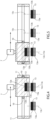
figures 6, 7 are similar tofigures 4, 5 and relate to a first variant of the gearshift lever assembly offigure 3 , -
figures 8, 9 are similar tofigures 4, 5 and relate to a second variant of the gearshift lever assembly offigure 3 , and -
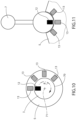
figures 10, 11 are schematic representations of respective alternative embodiments of the gearshift lever assembly according to the invention. - In
figure 1 , reference number 1 is used to indicate, as a whole, a motor vehicle. - For the purposes of the invention, the motor vehicle 1 could have any type of propulsion apparatus with any type of powertrain, for example an internal combustion engine, an electric motor or other known types of powertrain assemblies.
- The motor vehicle 1 has a plurality of
wheels 2 that allow it to be used. In order to cause the rotation of thewheels 2, the motor vehicle 1 also has a transmission, for example of a known type and not shown herein, which transmits the output motion generated by the engine to thewheels 2. - The transmission sets a gear ratio, namely a ratio of the respective speeds, between the engine and the
wheels 2. - The transmission could comprise a gearbox with a plurality of gears that can be selected to vary the gear ratio.
- In other words, the gearbox can be controlled to vary the gear ratio, for example by selectively engaging the gears.
- The gearbox could have a limited number of gears or even have a substantially infinite number of gears, thus defining a continuously variable transmission (CVT).
- Continuously variable transmissions, as well as gearboxes with a limited number of gears, are generally known per se in the automotive industry, so that they will not be described in greater detail or shown in a specific manner.
- The gearbox could also be absent, whereby the gear ratio could be fixed rather than variable. In this case, the rotation speed of the
wheels 2 would be determined by the engine, which could still be controllable in speed. - The motor vehicle 1 also has a passenger compartment 3 to accommodate a driver (
figure 2 ). - Inside the passenger compartment 3, the motor vehicle 1 comprises a gearshift lever assembly 4.
- Generally speaking, the gearshift lever assembly 4 is configured to allow the driver to control or select a state of the transmission of motion from the engine to the
wheels 2, in particular by means of the transmission. - More in detail, the gearshift lever assembly 4 is configured to control a control unit of the motor vehicle 1, which, in turn, controls the state of the transmission of motion in a consequent manner, namely in a manner consequent to the selection made by the driver by means of the gearshift lever assembly 4.
- Specifically, the gearbox of the transmission is of an automatic type, whereby the control unit adjusts the gear ratio, for example by selecting the engagement of a specific gear or by controlling a continuously variable transmission, based on the operation of the engine.
- In particular, the control unit extracts information on the operation of the engine from specific transducers coupled to the control unit and configured to monitor the operation of the engine.
- Here, i.e. with the automatic gearbox, the state of the transmission of motion could be selected by means of the gearshift lever assembly 4, for example from a park state P, a reverse state R, a neutral state N and a drive state D.
- These states of the transmission of motion are typical for motor vehicles with an automatic gearbox, so they will not be explained in detail, nor will the operation of the control unit for each one of the states of the motion transmission.
- The same states of the transmission of motion mentioned above could be selectable by means of the gearshift lever assembly 4 even if the gearbox were absent, as for example is the case in some fully electric motor vehicles, although with a known gearshift lever assembly that is different from the specific assembly 4 according to the invention.
- This is however not limiting, since the gearshift lever assembly 4 could have been used to select a specific gear of the gearbox, which in this case would have been manually operated. Here, each gear would define a respective state of transmission of motion, in addition to the aforementioned reverse and neutral states N, D.
- Therefore, in addition to one or more of the aforementioned states of transmission of motion, the states of transmission of motion that can be selected by means of the gearshift lever assembly 4 could include further states respectively associated with the engagement of specific gears of the gearshift or, more generally, with specific gear ratios between the engine and the
wheels 2, including the reverse gear ratios. - The assembly 4 comprises a
support base 5, which, in particular, is fixed to a body 6 of the motor vehicle 1. - Furthermore, the assembly 4 comprises a
lever body 7 graspable by the driver and coupled to thebase 5 in a movable manner along apath 8. - The
lever body 7 is movable along thepath 8 in a continuous manner, namely thelever body 7 can reach any point of thepath 8, which can be geometrically represented by a continuous line, i.e. without interruptions. - The
path 8 comprises a plurality of predetermined positions relative to thebase 5; the predetermined positions specifically correspond to the selection of the motion transmission states. - More specifically, the
path 8 or the assembly 4 have four positions corresponding to the selection of the park state, the reverse state, the neutral state and the drive state, respectively. - In the embodiment of
figure 3 , thebase 5 comprises aguide device 9 configured to guide thelever body 7 along thepath 8. - More in detail, the
lever body 7 comprises one ormore slides 10 coupled to theguide device 9 in a sliding manner along thepath 8. - In particular, the
guide device 9 comprises at least twoguides 11, more in particular comprising respective beams with a C-shaped cross section facing one another other. Theguides 11 substantially extend according to thepath 8 and are engaged in a sliding manner by tworespective slides 10 of thelever body 7. - With reference to
figure 3 , thepath 8 extends on a plane according to a line, in particular consisting of one or more straight segments. - The line of the
path 8 is defined, more in particular, by two straight line sections or segments, perpendicular to one another and having two respective coincident end points. Therefore, in other words, the line of thepath 8 is L-shaped, in that one of the two segments is in particular shorter than the other. - The
path 8 could clearly have been different and, for example, even be defined by two H-shaped portions adjacent to one another and with a coincident long branch, i.e. similarly to the path of some known gearshift levers for controlling a five-speed manual transmission with additional reverse gear. - The assembly 4 further comprises a
magnet 12 fixed relative to thelever body 7, namely carried by thelever body 7 in a fixed position. - The
magnet 12 has two oppositemagnetic poles axis 12c, more in particular of the straight kind. - In the specific example of
figures 4, 5 , as well as in the variants offigures 6-9 , themagnetic axis 12c is perpendicular to thepath 8 or, more precisely, to the plane of thepath 8. - Furthermore, the assembly 4 comprises a number of
further magnets 13 at least equal to the predetermined positions. - The
magnets 13 are carried by thebase 5 in respective fixed positions, namely they are fixed relative to thebase 5. - Furthermore, although they are fixed to the
base 5, themagnets 13 are arranged or distributed along or according to thepath 8, in particular at the predetermined positions. - Just like the
magnet 12, one or each one of themagnets 13 also has two oppositemagnetic poles axis 12c, more in particular of the straight kind. In the example offigures 4, 5 , themagnetic axes 13c are parallel to themagnetic axis 12c. - The
poles 13b are (magnetically) opposite relative to thepole 12b. - Each one of the
magnets 13 is arranged so that therelative pole 13b magnetically cooperates with thepole 12b in a corresponding one of the predetermined positions of thelever body 7, namely when thelever body 7 is in said predetermined position. In this way, the correspondingmagnet 13 exerts a magnetic attraction upon themagnet 12; indeed, theopposite poles - Therefore, in other words, when the
lever body 7 reaches one of the predetermined positions, themagnet 12 cooperates or interacts with a corresponding one of themagnets 13. Themagnet 12, more precisely, is attracted by the correspondingmagnet 13. - This guarantees a stability of each one of the predetermined positions, since the driver has to overcome the magnetic attraction between the
magnet 12 and the corresponding one of themagnets 13 in order to move thelever body 7 from the relevant predetermined position. Therefore, while moving thelever body 7 from any one of the predetermined positions, the driver receives a feeling of resistance due to the magnetic attraction between themagnet 12 and thecorresponding magnet 13. - In the example of
figures 4, 5 , when thelever body 7 is in each one of the predetermined positions, thepole 12b and thepole 13b of thecorresponding magnet 13 are aligned along themagnetic axis 13c or themagnetic axis 12c, here coinciding with one another. - Still in this last example, the
magnets 13 corresponding to two adjacent or successive predetermined positions according to thepath 8 are spaced apart from one another along the path 8 (namely, parallel to it) by means of an empty space or in any case without magnets. - Furthermore, in this last example, for each predetermined position there is one and only one corresponding
magnet 13, which faces and, more precisely, is aligned with themagnet 12 according to themagnetic axes lever body 7 is in the corresponding predetermined position. - The variant of
figures 6, 7 is similar to that offigures 3 ,4 , so that only the distinctive aspects thereof will be described using, where possible, the same reference symbols to indicate components shared by both variants. - In the example of
figures 6, 7 , each one of themagnetic axes 13c forms acute angles with themagnetic axis 12c, when thelever body 7 is in the corresponding predetermined position. In other words, for each one of the predetermined positions, themagnetic axis 12c is inclined with respect to themagnetic axis 13c of thecorresponding magnet 13 and incident thereto. - In particular, two
magnets 13 could correspond to a predetermined position; indeed, in the example offigures 6, 7 , twomagnets 13 correspond to the predetermined position associated with the neutral state. - Except for the predetermined position with two corresponding
magnets 13, the adjacent orsuccessive magnets 13 along the path have the respectivemagnetic axes 13b that form, between them, a relative acute angle by meeting towards thelever body 7. The twomagnets 13 corresponding to one single predetermined position have the relativemagnetic axes 13c that form, between them, a relative acute angle by meeting on the opposite side with respect to the one where thelever body 7 is located. - In this way, in practice, at a portion of the
path 8 between two adjacent or successive predetermined positions along thepath 8, the twoadjacent magnets 13 respectively corresponding to the two predetermined positions form a depression or a V-shaped configuration towards thelever body 7 according to the direction of themagnetic axis 12c. - In each predetermined position of the
lever body 7, themagnet 12 and the one or twomagnets 13 corresponding to the predetermined position in question have a minimum distance from one another along themagnetic axis 12c. - Indeed, in the case of the predetermined position with two corresponding
magnets 13, both the twomagnets 13 have a minimum distance from themagnet 12 along themagnetic axis 12c, when thelever body 7 is in said predetermined position. Here, the twomagnets 13 form a wedge or an upside-down V-shaped configuration towards thelever body 7. - In this way, the magnetic attraction gradually decreases as the
lever body 7 moves away from each one of the predetermined positions. In particular, on the other hand, the magnetic attraction increases again as thelever body 7 approaches the adjacent or successive predetermined position according to thepath 8, until the maximum magnetic attraction is reached when thelever body 7 reaches the adjacent or successive predetermined position. - To sum up, for a predetermined position, the
magnet 12 and themagnet 13 corresponding to the predetermined position respectively have themagnetic poles magnetic poles magnetic poles magnetic axes - Furthermore, in particular, when the
lever body 7 is in a predetermined position, themagnetic axis 12c forms an acute angle with themagnetic axis 13c of themagnet 13 corresponding to the predetermined position. Furthermore, here (when thelever body 7 is in a predetermined position), themagnet 12 and themagnet 13 corresponding to the predetermined position have a minimum distance from one another along themagnetic axis 12c, such that the magnetic attraction (between themagnets 12, 13) gradually decreases as thelever body 7 moves away from the predetermined position. - Alternatively or in addition, the
magnet 12 and eachmagnet 13 respectively have themagnetic pole 12a and the correspondingmagnetic pole 13a respectively opposite themagnetic pole 12b and the relativemagnetic pole 13b, as well as, in turn, respectively aligned with themagnetic pole 12b and the relativemagnetic pole 13b according to themagnetic axis 12c and the correspondingmagnetic axis 13c. Furthermore, in particular, themagnetic axis 12c forms a relative acute angle with eachmagnetic axis 13c when thelever body 7 is in the corresponding predetermined position, where themagnet 12 and thecorresponding magnet 13 have a minimum distance from one another along themagnetic axis 12c, such that the magnetic attraction gradually decreases as thelever body 7 moves away from the corresponding predetermined position. - Still with reference to the example of
figures 6, 7 , themagnets 13 are distributed along thepath 8 in a substantially continuous manner, i.e. such that a magnetic attraction continuously subsists during a movement of thelever body 7 traversing thewhole path 8. - More precisely, the
magnets 13 define a path of their own identical to thepath 8 but arranged on a different plane parallel to that of thepath 8. For this reason, the two paths can be considered, as a whole, aspath 8. - The term substantially used above relates to the fact that a physical separation may exist between
adjacent magnets 13, but the gap between theadjacent magnets 13 remains negligible in the sense that the magnetic attraction is not interrupted by the passage of thelever body 7 from one predetermined position to another adjacent or successive one. - Rather, the magnetic attraction rises and falls in a wave-like manner with magnetic attraction peaks at the predetermined positions.
- The variant of
figures 8, 9 is similar to that offigures 3 ,4 , so that only the distinctive aspects thereof will be described using, where possible, the same reference symbols to indicate components shared by both variants. - In the variant of
figures 8, 9 , the assembly 4 comprisesfurther magnets 14, each having, just like each one of themagnets 13, two oppositemagnetic poles axis 14c, more in particular of the straight kind. - In the example of
figures 8, 9 , themagnetic axes 14c are parallel to themagnetic axis 12c, as well as to themagnetic axes 13c. - The
poles 13b are (magnetically) concordant relative to thepole 12b. - The
magnets 14 are carried by thebase 5 in respective fixed positions; each one of themagnets 14 is arranged so that therelative pole 14b magnetically cooperates with thepole 12b when thelever body 7 is in a corresponding intermediate position along thepath 8 between two adjacent or successive predetermined positions, so that themagnet 14 exerts a magnetic repulsion upon themagnet 12 during a transit of the lever body between the two adjacent or successive predetermined positions. - More in detail, each
magnet 14 is arranged between twocorresponding magnets 13 that are adjacent or successive to one another along thepath 8. - Specifically, each
magnet 14 is aligned with themagnet 12 along themagnetic axis 12c when thelever body 7 moves to the corresponding intermediate position. - Therefore, in particular, the
magnets magnets 13 mentioned above) according to an alternated sequence. In other words, eachmagnet 13 is followed by amagnet 14 according to thepath 8 and vice versa. - Preferably, the
magnets magnets magnet 12 continuously subsists during a movement of thelever body 7 traversing thewhole path 8. - Again, the term substantially relates to the fact that a physical separation may exist between two
successive magnets successive magnets magnet 12 is not interrupted by the passage of thelever body 7 from one predetermined position to another adjacent or successive one. - In practice, the magnetic interaction of the
magnet 12 during the travel of thelever body 7 along theentire path 8 consists of an alternation between attraction with each one of themagnets 13, whenever thelever body 7 reaches the corresponding predetermined position, and repulsion with each one of themagnets 14, whenever thelever body 7 moves between two adjacent or successive corresponding predetermined positions. - The embodiment of
figure 10 will be described below. This last embodiment is similar to the one offigure 3 , whereby all the variants offigures 3-8 can also be applied to the embodiment offigure 10 , even though they are not explicitly repeated for the sake of conciseness. The embodiment offigure 10 will be described only in what distinguishes it from that offigure 3 , possibly using the same reference symbols to indicate the same components. - In the embodiment of
figure 10 , thelever body 7 comprises aknob 70 that can rotate relative to thebase 5 around arotation axis 71. - Therefore, the
path 8 is circular, i.e. it is defined by an arc of a circle. - Furthermore, the
magnetic axes magnets 14 are optionally provided, even though they are not shown infigure 9 ) are directed radially relative to therotation axis 71. - The embodiment of
figure 11 is similar to the one offigure 10 , so that it will be described only in the aspects that distinguish it therefrom, possibly using the same reference symbols to indicate the same components. - Again, the contents of the variants of
figures 6-9 are applicable to the embodiment offigure 11 , even though they are not explicitly repeated for the sake of conciseness. - In the embodiment of
figure 11 , thelever body 7 is coupled to thebase 5 by means of a ball coupling, such that, in particular, thelever body 7 and thebase 5 form part of a ball joint. - Therefore, in this case, the
path 8 extends along a spherical surface, instead of extending on a plane as is the case in other embodiments described and shown herein. The spherical surface is virtually defined by the ball coupling. - Furthermore, the
magnetic axes magnets 14 are optionally provided, even though they are not shown infigure 10 ) are directed radially relative to the centre of the spherical surface. - Owing to the above, the advantages of the gearshift lever assembly 4 according to the invention are evident.
- The magnetic attraction of the
magnet 12 with therespective magnets 13 in the corresponding predetermined positions is perfectly suitable for returning feelings to the driver that are similar to those provided by the mechanical members of known solutions. - In addition, the magnetic cooperation is not noisy and does not involve wear of parts in mechanical contact.
- Furthermore, the alternation between magnetic attraction and repulsion guaranteed by the alternation between the
magnets figures 8, 9 , is particularly advantageous as it corresponds to a greater feeling of fluidity of the movement of thelever body 7 for the driver, as well as to a more energetic engagement/disengagement feeling. - Finally, the gearshift lever assembly 4 according to the invention can clearly be subject to changes and variants, which, though, do not go beyond the scope of protection defined by the appended claims.
- In particular, the number and shape of the components described and shown herein could be different.
Claims (11)
- - Gearshift lever assembly (4) for a motor vehicle (1), the assembly comprising,- a support base (5),- a lever body (7) graspable by a driver of the motor vehicle and movably coupled to the support base (5) along a path (8) comprising a plurality of predetermined positions relative to the support base (5),- a first magnet (12) fixed relative to the lever body (7) and having a first magnetic pole (12b), and- at least one corresponding second magnet (13) for each of said predetermined positions, the second magnet (13) having a relative second magnetic pole (13b) opposite to the first magnetic pole (12b) and being carried by the support base (5) in a relative fixed position, such that said second pole (13b) magnetically cooperates with the first pole (12b) when the lever body (7) is in the corresponding predetermined position of said predetermined positions, so that the corresponding second magnet (13) exerts a magnetic attraction on the first magnet (12).
- - The gearshift assembly according to claim 1, wherein the first pole (12b) and the second pole (13b) are aligned along a straight direction (12c, 13c) when the lever body (7) is in said corresponding predetermined position.
- - gearshift lever assembly according to claim 1, wherein the first magnet (12) and each second magnet (13) respectively have a third magnetic pole (12a) and a fourth magnetic pole (13a) respectively opposite the first pole and the second pole (12b, 13b), as well as in turn aligned with the first pole and the second pole (12b, 13b) respectively according to a first rectilinear direction (12c) and a second rectilinear direction (13c,) the first rectilinear direction (12c) forming with the second rectilinear direction (13c) an acute angle when the lever body (7) is in the corresponding predetermined position, the first and the second magnets (12, 13) having a minimum distance between each other along the first rectilinear direction (12c) when the lever body (7) is in the corresponding predetermined position, such that the magnetic attraction gradually decreases with a departure of the lever body (7) from the corresponding predetermined position.
- - The gearshift lever assembly according to claim 3, wherein the second magnets (13) are distributed along the path (8) such that the second rectilinear directions (13c) of second magnets (13) adjacent to each other form a further relative acute angle.
- - The gearshift lever assembly according to any one of the preceding claims, further comprising a third magnet (14) having a fifth magnetic pole (14b) concordant with the first pole (12b) and carried by the support base (5) in a relative fixed position such that the fifth pole (14b) magnetically co-operates with the first pole (12b) when the lever body (7) is in a corresponding intermediate position along the path (8) between two adjacent predetermined positions of said predetermined positions, so that the third magnet (14) exerts magnetic repulsion on the first magnet (12) during a transit of the lever body (7) between said two adjacent predetermined positions.
- - The gearshift lever assembly according to claim 4, wherein the second magnets (13) are distributed along the path (8) in a substantially continuous manner, such that magnetic attraction subsists continuously during a movement of the lever body (7) traversing the whole path (8).
- - The gearshift lever assembly according to claim 5, comprising one or more further third magnets (14) in addition to said third magnet (14), wherein the second and third magnets (13, 14) are distributed along the path (8) in an alternating sequence and preferably in a substantially continuous manner, such that a magnetic interaction with the first magnet (12) subsists continuously during a movement of the lever body (7) traversing the entire path (8).
- - The gearshift lever assembly according to any one of the preceding claims, wherein the path (8) extends on a plane according to a L-shaped line.
- - The gearshift lever assembly according to any one of claims 1 to 7, wherein the lever body (7) comprises a knob (70) rotatable with respect to the support base (5) about a rotational axis (71), wherein the path (8) is circular about the rotational axis (71).
- - The gearshift lever assembly according to any one of claims 1 to 7, wherein the lever body (7) is coupled to the support base (5) by a spherical coupling, whereby the path (8) extends along a spherical surface virtually defined by the spherical coupling.
- - Motor vehicle (1) comprising a gearshift lever assembly (4) according to any one of the preceding claims.
Applications Claiming Priority (1)
| Application Number | Priority Date | Filing Date | Title |
|---|---|---|---|
| IT202300024669 | 2023-11-21 |
Publications (1)
| Publication Number | Publication Date |
|---|---|
| EP4560165A1 true EP4560165A1 (en) | 2025-05-28 |
Family
ID=89897652
Family Applications (1)
| Application Number | Title | Priority Date | Filing Date |
|---|---|---|---|
| EP24213929.3A Pending EP4560165A1 (en) | 2023-11-21 | 2024-11-19 | Gearshift lever assembly with magnetic feeling for a motor vehicle |
Country Status (3)
| Country | Link |
|---|---|
| US (1) | US20250164006A1 (en) |
| EP (1) | EP4560165A1 (en) |
| CN (1) | CN120027194A (en) |
Citations (6)
| Publication number | Priority date | Publication date | Assignee | Title |
|---|---|---|---|---|
| JPH02105651U (en) * | 1989-02-09 | 1990-08-22 | ||
| KR102152702B1 (en) * | 2014-05-23 | 2020-09-07 | 에스엘 주식회사 | electronic control transmission |
| IT201900005726A1 (en) * | 2019-04-12 | 2020-10-12 | Tecno Elett Ravasi S R L | Trigger for a manually operated controller |
| EP3658799B1 (en) * | 2017-08-31 | 2021-10-13 | Küster Holding GmbH | Shifting device with a magnetic locking mechanism |
| CN113803453A (en) * | 2020-06-11 | 2021-12-17 | 广州汽车集团股份有限公司 | Knob-type shifting mechanism and system |
| KR102449851B1 (en) * | 2017-11-20 | 2022-10-04 | 현대자동차주식회사 | Shift lever assembly for automatic transmission vehicle |
Family Cites Families (8)
| Publication number | Priority date | Publication date | Assignee | Title |
|---|---|---|---|---|
| DE3138827A1 (en) * | 1981-09-30 | 1983-04-14 | Wabco Westinghouse Fahrzeugbremsen GmbH, 3000 Hannover | GEAR SELECTOR FOR A GEARBOX |
| SE457680B (en) * | 1987-01-15 | 1989-01-16 | Toecksfors Verkstads Ab | ELECTRONIC SWITCH INCLUDING ONE IN A MUCH MOVABLE MANUAL |
| DE4109544A1 (en) * | 1991-03-22 | 1992-09-24 | Kirsten Elektrotech | Multipurpose electric switch - has pivotable actuator lever and magnet arrangements of alternately poled magnets concentrically around pivot axis |
| JP2002254949A (en) * | 2001-03-02 | 2002-09-11 | Tokai Rika Co Ltd | Shift device |
| JP2006244885A (en) * | 2005-03-04 | 2006-09-14 | Shin Caterpillar Mitsubishi Ltd | Dial operating tool |
| DE102006002634B4 (en) * | 2005-07-19 | 2009-11-26 | Preh Gmbh | Control element with tilt-feel |
| DE102006012890A1 (en) * | 2006-03-13 | 2007-09-20 | Valeo Schalter Und Sensoren Gmbh | Switch, in particular vehicle switch, evaluation unit therefor and associated switch unit |
| DE102012216548B4 (en) * | 2011-11-30 | 2017-02-09 | Preh Gmbh | Control element with magnetic haptic generation |
-
2024
- 2024-11-11 US US18/943,097 patent/US20250164006A1/en active Pending
- 2024-11-19 EP EP24213929.3A patent/EP4560165A1/en active Pending
- 2024-11-19 CN CN202411657219.9A patent/CN120027194A/en active Pending
Patent Citations (6)
| Publication number | Priority date | Publication date | Assignee | Title |
|---|---|---|---|---|
| JPH02105651U (en) * | 1989-02-09 | 1990-08-22 | ||
| KR102152702B1 (en) * | 2014-05-23 | 2020-09-07 | 에스엘 주식회사 | electronic control transmission |
| EP3658799B1 (en) * | 2017-08-31 | 2021-10-13 | Küster Holding GmbH | Shifting device with a magnetic locking mechanism |
| KR102449851B1 (en) * | 2017-11-20 | 2022-10-04 | 현대자동차주식회사 | Shift lever assembly for automatic transmission vehicle |
| IT201900005726A1 (en) * | 2019-04-12 | 2020-10-12 | Tecno Elett Ravasi S R L | Trigger for a manually operated controller |
| CN113803453A (en) * | 2020-06-11 | 2021-12-17 | 广州汽车集团股份有限公司 | Knob-type shifting mechanism and system |
Also Published As
| Publication number | Publication date |
|---|---|
| US20250164006A1 (en) | 2025-05-22 |
| CN120027194A (en) | 2025-05-23 |
Similar Documents
| Publication | Publication Date | Title |
|---|---|---|
| CN101985978B (en) | Shifting apparatus for double clutch transmission | |
| US5689997A (en) | Electric gearshift mechanism for change-speed gearboxes of motor vehicles | |
| US4570765A (en) | Gearshift system for an automobile | |
| US7886627B2 (en) | Coupling device and transmission system including the coupling device | |
| EP0443424A1 (en) | Transmission control system for cars comprising a variable speed drive | |
| KR20190056124A (en) | Automotive transmission | |
| EP4560165A1 (en) | Gearshift lever assembly with magnetic feeling for a motor vehicle | |
| KR101971187B1 (en) | Gear Actuator of Automated Manual Transmission | |
| KR101846670B1 (en) | Gear shifting device for vehicles | |
| US10088041B2 (en) | Apparatus for controlling shift of manual transmission | |
| US4565108A (en) | Gearshift apparatus for an automobile | |
| US20040159171A1 (en) | Gearshift operating device | |
| JP2016044745A (en) | Automatic transmission device of transmission | |
| CN103671865A (en) | Apparatus for shifting gears of a transmission | |
| KR20180032948A (en) | Shift lever apparatus for electronic shift system | |
| KR101795734B1 (en) | Gear actuator of Dual clutch transmission | |
| KR101682191B1 (en) | A transmission controller for vehicle | |
| KR100558299B1 (en) | Vehicle shift control | |
| KR102289737B1 (en) | Automotive transmission | |
| CN103089982A (en) | Shifter assembly for providing mechanical and electronic actuation to a transmission of a vehicle and a method of operating the shifter assembly | |
| JP2020159364A (en) | Shift control device | |
| US20250273410A1 (en) | Inhibitor switch | |
| KR100188753B1 (en) | Shift control structure of manual transmission for automobile | |
| KR20190064871A (en) | Automotive transmission | |
| KR20200081587A (en) | Shift apparatus of transmisson |
Legal Events
| Date | Code | Title | Description |
|---|---|---|---|
| PUAI | Public reference made under article 153(3) epc to a published international application that has entered the european phase |
Free format text: ORIGINAL CODE: 0009012 |
|
| STAA | Information on the status of an ep patent application or granted ep patent |
Free format text: STATUS: THE APPLICATION HAS BEEN PUBLISHED |
|
| AK | Designated contracting states |
Kind code of ref document: A1 Designated state(s): AL AT BE BG CH CY CZ DE DK EE ES FI FR GB GR HR HU IE IS IT LI LT LU LV MC ME MK MT NL NO PL PT RO RS SE SI SK SM TR |
|
| STAA | Information on the status of an ep patent application or granted ep patent |
Free format text: STATUS: REQUEST FOR EXAMINATION WAS MADE |
|
| 17P | Request for examination filed |
Effective date: 20251125 |
|
| STAA | Information on the status of an ep patent application or granted ep patent |
Free format text: STATUS: EXAMINATION IS IN PROGRESS |