EP4560071A1 - Konische refinerfüllung - Google Patents
Konische refinerfüllung Download PDFInfo
- Publication number
- EP4560071A1 EP4560071A1 EP24215464.9A EP24215464A EP4560071A1 EP 4560071 A1 EP4560071 A1 EP 4560071A1 EP 24215464 A EP24215464 A EP 24215464A EP 4560071 A1 EP4560071 A1 EP 4560071A1
- Authority
- EP
- European Patent Office
- Prior art keywords
- refining
- filling
- conical
- refiner
- stator
- Prior art date
- Legal status (The legal status is an assumption and is not a legal conclusion. Google has not performed a legal analysis and makes no representation as to the accuracy of the status listed.)
- Pending
Links
Images


Classifications
-
- D—TEXTILES; PAPER
- D21—PAPER-MAKING; PRODUCTION OF CELLULOSE
- D21D—TREATMENT OF THE MATERIALS BEFORE PASSING TO THE PAPER-MAKING MACHINE
- D21D1/00—Methods of beating or refining; Beaters of the Hollander type
- D21D1/20—Methods of refining
- D21D1/22—Jordans
- D21D1/24—Jordan rolls
-
- D—TEXTILES; PAPER
- D21—PAPER-MAKING; PRODUCTION OF CELLULOSE
- D21D—TREATMENT OF THE MATERIALS BEFORE PASSING TO THE PAPER-MAKING MACHINE
- D21D1/00—Methods of beating or refining; Beaters of the Hollander type
- D21D1/20—Methods of refining
- D21D1/22—Jordans
Definitions
- the invention relates to conical refiners for refining fibrous material and especially to a conical refining filling for a conical refiner for refining fibrous material.
- Conical refiners used for refining fibrous material i.e., pulp suspension or pulp being a mixture comprising at least water and virgin fibrous material and/or recycled fibrous material
- Conical refiners used for refining fibrous material comprise typically two conical refining elements that are arranged within each other opposite to each other such that there is a refining gap therebetween, and to turn relative to each other, i.e., one or both is/are rotating.
- the refining elements comprise refining surfaces provided with refining bars and refining grooves therebetween, the refining bars being intended to defibre and refine the fibrous material to be refined and the refining grooves being intended to convey the material to be refined forward along the refining surfaces.
- Figure 1 discloses schematically a prior art refining system with three conical refiners 1, 2, 3 in series with each other.
- a problem with the prior art refining system of Figure 1 is a controllability of the refining system in view of for example a pressure control of the refining system.
- each single refiner 1, 2, 3 causes in its part a pressure increase in the refining system.
- This pressure increase may be with smaller refiners about 1 to 1.5 bars per each refiner but with larger refiners, such as with refiners having a diameter of about 1 metre at the larger end thereof, even up to 2 to 2.5 bars per each refiner.
- a maximum pressure typically allowed in the refining systems is about 6 to 7 bars due to a durability of refiner structures, additional measures may be needed for the pressure control in the refining system.
- One possible additional measure for the pressure control of the refining system may be a recirculation system, such as the recirculation line 4 of Figure 1 , for recirculating at least part of the material already refined back to the series of the refiners to refine it again.
- a problem with the recirculation system is however an increase in the cost of the refining system due to additional piping and flow control devices and instrumentation required for controlling the recirculation.
- Another problem of the recirculation system is also an increase in the amount of energy used per each ton of the produced refined fibrous material, which amount of energy used for refining is the higher the higher is the proportion of the recirculated fibrous material of the whole amount of the fibrous material to be refined.
- An object of the present invention is to provide a novel conical refining filling for a conical refiner for refining fibrous material as well as a novel method for refining fibrous material.
- the invention is based on the idea of arranging in the conical refiner at least one recirculation flow that is internal to the refiner for recirculating at least one flow of the fibrous material from a refiner chamber of the refiner back to a refining gap of the refiner.
- An advantage of the invention is a reduced pressure increase in the refiner because the recirculation flow of the fibrous material from the refiner chamber back to the refining gap decreases a pressure build-up in the refiner, i.e., limits the pressure built from the refiner, thereby eliminating too high pressure at the outlet of the refiner.
- This reduced pressure build-up in a single refiner provides a possibility to arrange a higher number of refiners in series without exceeding a maximum allowable pressure in the refining system, i.e., allows to run several refiners without having too high pressures.
- FIG. 2 shows schematically a side view of a conical refiner 10 in partial cross-section.
- the refiner 10 may be used for refining fibrous material, such as a wood material containing lignocellulose or another fibrous material suitable to be used for manufacturing paper or paperboard, for example.
- the fibrous material is fed into the refiner 10 in a form of a pulp suspension, i.e., pulp, that is a mixture comprising at least water and virgin fibrous material and/or recycled fibrous material and possibly some additives.
- the consistency of the fibrous material to be refined is typically between 2-6%.
- the refiner 10 of Figure 2 comprises a main frame 20, a refiner chamber 30 supported to the main frame 20, a feed end frame 40 supported to the refiner chamber 30, a stationary refining element 50, i.e., a stator 50, a rotatable refining element 60, i.e., a rotor 60, and a shaft 70 connected to the rotor 60 for rotating the rotor 60.
- the shaft 70 is supported at least to the main frame 20 by appropriate not-shown bearings.
- the stator 50 and the rotor 60 are arranged at least partly within each other opposite to each other such that the rotor 60 is at least partly inside the stator 50, i.e., the stator 50 at least partly surrounds the rotor 60.
- the stator 50 forms an outer refining element and the rotor 60 forms an inner refining element arranged inside the stator 50.
- the fibrous material is refined in the refining gap 12, i.e., the fibrous material is subjected to the refining effect in the refining gap 12 when the refiner 10 is in operation and the rotor 60 rotates relative to the stator 50.
- the stator 50 comprises a conical refining filling 80.
- the conical stator refining filling 80 i.e., a conical stationary refining filling 80, is a solid one-piece-element configured to form at least part of the stator 50 and intended to subject for its part the refining effect to the fibrous material to be refined.
- Figures 2 and 3 show a schematic cross-sectional side view of a conical stator refining filling 80 according to the disclosed solution.
- Figure 4 is a schematic front view of a conical stator refining filling 80 intended to form at least part of the conical stator refining element in a conical refiner.
- stator refining filling 80 has a longitudinal direction LD and a circumferential direction CD and, in the longitudinal direction LD, a first end 80a of smaller diameter and a second end 80b of larger diameter.
- the stator refining filling 80 has an inner circumference 80IC to be directed towards the rotor 60, and the inner circumference 80IC of the stator refining filling 80 comprises a refining surface 82 provided with refining bars 84 and refining grooves 86 therebetween.
- the refining bars 84 are intended to defibre and refine the fibrous material to be refined and the refining grooves 86 are intended to convey the material to be refined forward along the refining surface 82.
- the stator refining filling 80 has an outer circumference 80OC to be directed away from the rotor 60, i.e., towards the feed end frame 40.
- the stator refining filling 80 may for example be supported to the refiner chamber 30 and/or to the feed end frame 40.
- the rotor 60 comprises a frame 62, that may also be called a hub 62, and a conical rotor refining filling 90, i.e., a conical rotatable refining filling 90, supported to the hub 62 of the rotor 60.
- the conical rotor refining filling 90 is also a solid one-piece-element configured to form a part of the rotor 60 and intended to subject for its part the refining effect to the fibrous material to be refined.
- the rotor refining filling 90 also has, resembling the structure of the stator refining filling 80, a longitudinal direction and a circumferential direction and, in the longitudinal direction, a first end 90a of smaller diameter and a second end 90b of larger diameter.
- the rotor refining filling 90 has an inner circumference 90IC to be directed towards the hub 62 of the rotor 60 and an outer circumference 90OC to be directed towards the stator 50.
- the outer circumference 90OC of the rotor refining filling 90 comprises a refining surface 92 provided with refining bars and refining grooves therebetween.
- the rotor 60 is connected to a not-shown driving motor by the shaft 70 so that the rotor 60 can be rotated relative to the stator 50 to an intended rotation direction.
- the refiner 10 typically also comprises a not-shown loading device which can be used for moving the rotor 60 attached to the shaft 70 back and forth in the longitudinal direction of the rotor 60 to adjust a size of the refining gap 12 between the stator 50 and the rotor 60.
- the fibrous material is fed into the refiner 10, i.e., into the refining gap 12 therein, through an inlet 14 in a manner shown schematically by arrow IF.
- the inlet 14 and the volume between the inlet 14 and the refining gap 12 forms a feed or a feed section of the refiner 10 for supplying the fibrous material to be refined into the refining gap 12.
- the fibrous material flows through the refining gap 12, as shown schematically by arrows F, and the refining effect is subjected to the fibrous material in the refining gap 12, when the rotor 60 rotates relative to the stator 50.
- the refined fibrous material flows out of the refiner 10 through an outlet 16 in a manner shown schematically by arrow OF.
- a general construction and an operation of conical refiners are generally known to a person skilled in the art and they are therefore not considered herein in more detail.
- a pressure increase takes place in the refining system.
- This pressure increase is caused in its part by each one or more refiner forming at least part of the refining system.
- one reason for the pressure increase is the geometry of the conical refiner, i.e., the increasing diameter of the stator and the rotor.
- An amount of this pressure increase depends for example on the steepness of the conical geometry of the stator and the rotor.
- a second reason for the pressure increase is a rotational speed of the rotor, i.e., the higher the rotational speed of the rotor, the higher the pressure increase taking place in the refiner.
- a third reason for the pressure increase is a geometry of the refining surfaces in the stator and the rotor, i.e., a geometry of the refining bars and the refining grooves in the stator and the rotor.
- the geometry of the refining bars and the refining grooves is designed such that the refining bars and the refining grooves promote the flow of the fibrous material to be refined towards the second ends of the stator and the rotor, i.e., in other words, the refining bars and the refining grooves are designed to pump the fibrous material to be refined towards the second ends of the stator and the rotor.
- This further increases a pressure increase towards the second ends of the stator and the rotor. At least these reasons cause the pressure increase from an inlet of the refiner towards an outlet of the refiner in the conical refiners.
- This pressure increase may be about 1 to 1.5 bars per each refiner in smaller refiners but with larger refiners, such as with refiners having a diameter of about 1 metre at the larger end of the stator/rotor, the pressure increase may be even up to 2 to 2.5 bars per each refiner. Because a maximum pressure typically allowed in the refining systems is about 6 to 7 bars, additional measures may be needed for the pressure control in refining systems especially with two or more refiners in series with each other.
- Figure 2 further discloses an embodiment to solve the problem of the pressure increase in a single refiner and thereby to the problem of the pressure increase in a refining system comprising two or more refiners connected in series with each other.
- the refiner 10 of Figure 2 is arranged to provide at least one recirculation flow of the fibrous material to be refined between the refiner chamber 30 and the first end 12a of the refining gap 12 for recirculating at least one flow of the fibrous material from the refiner chamber 30 back to the refining gap 12.
- Figure 2 further, together with Figures 3 and 4 and the related description below, discloses an embodiment for arranging the at least one recirculation flow RF between the refiner chamber 30 and the first end 12a of the refining gap 12 in the refiner 10.
- the conical stator refining filling 80 comprises, on its outer circumference 80OC, at least one flange 110 projecting away from the outer circumference 80OC of the refining filling 80 and extending over the outer circumference 80OC of the refining filling 80 in the circumferential direction CD of the refining filling 80.
- the flange 110 comprises a first side surface 110a facing at least partly towards the first end 80a of the refining filling 80, a second side surface 110b facing at least partly towards the second end 80b of the refining filling 80 and open sections, in the embodiment of the Figures 2 to 4 holes 120, extending through the flange 110 between the first side surface 110a and the second side surface 110b of the flange 110.
- the refiner 10 In response to the introduction of the at least one open section, such as a hole 120, through the flange 110, the refiner 10 is arranged to form the at least one recirculation flow RF flowing from the refiner chamber 30 to the first end 12a of the refining gap 12, or in other words from the refiner chamber 30 to the feed of the refiner, for recirculating at least one recirculation flow RF of the fibrous material from the refiner chamber 30 back to the refining gap 12 along an outer circumference of the conical stator refining filling 80.
- An effect of the disclosed solution is a reduced pressure increase in the refiner because the recirculation flow of the fibrous material from the refiner chamber back to the refining gap decreases a pressure build-up in the refiner, thereby eliminating too high pressure at the outlet of the refiner.
- This reduced pressure build-up in a single refiner provides a possibility to arrange a higher number of refiners in series without exceeding a maximum allowable pressure in the refining system.
- the disclosed solution provides a self-balancing or self-regulating solution for the pressure control in the refiner and for the recirculation of the fibrous material such that the higher is the flow-pressure build-up in the refiner, the higher is the proportion of the recirculated flow of the fibrous material of the whole amount of the flow of the fibrous material to be refined in the refiner, which efficiently reduces the pressure build-up in the refiner.
- the size and number of the open sections, such as the size and number of the holes 120, can be varied to adjust a pressure build-up level in the refiner and the amount of recirculation flow of the fibrous material to be refined.
- the diameter of the larger end of the refining filling 80 may for example be 460mm to 1m
- the outer diameter of the flange 110 may for example be 500mm to 1100 mm
- the diameter of the holes 120 may be for example up to 30mm of whatever shape. The bigger the refiner the bigger the holes.
- the disclosed solution eliminates the need for the additional piping for recirculating the fibrous material to be refined as well as the need for the flow control devices and instrumentation required for controlling the recirculation. This has a remarkable decreasing effect, even a decrease of several tens of thousands of euros, in the expenses of refining systems with two or more refiners in series.
- the disclosed solution is also expected to provide a more heterogeneous refining because a portion of the fibrous material to be refined may recirculate even several times through one or more refiners in a series of at least two refiners. This may have a positive effect on some characteristics of the refined fibrous material, such as providing a higher tear index as generally expected with heterogeneous refining, but still not having any remarkable effect on some other characteristics of the refined fibrous material, such as a drainability or tensile index of the refined fibrous material. This provides a possibility to design different refining applications for various paper grades.
- One effect is also a reduced energy consumption per each ton of the produced refined fibrous material because of avoiding recirculating the fibrous material through external piping system.
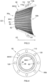
- Figures 5a and 5b show schematically some test results of a test run, wherein the operation of the disclosed solution was compared with the operation of a prior art solution in a refining system of a single refiner.
- the fibrous material to be refined in the test run was a bleached long fibre kraft pulp.
- a cutting-edge-length of the refining fillings in the refiner applied was 3.7 km per revolution and the flange of the stator refining filling comprised 18 holes with a diameter of 20 millimetres.
- Figure 5a shows the pressure increase in the refiner as a function of a forward flow of the fibrous material to be refined in the refiner.
- the lower diagram in Figure 5a shows the pressure increase when the holes in the stator refining filling were open, i.e., the recirculation flow of the fibrous material from the refiner chamber back to the feed of the refiner was enabled.
- the upper diagram in Figure 5a shows the pressure increase when the holes in the stator refining filling were plugged, i.e., the recirculation flow of the fibrous material from the refiner chamber back to the feed of the refiner was disabled.
- the upper diagram of Figure 5a thus shows the pressure increase taking place in an operating situation of a prior art refiner.
- Figure 5a shows a remarkable decrease in the pressure increase in the single refiner when the disclosed solution was applied.
- Figure 5b shows a relationship of a forward flow, a recirculation flow, and a total flow of the fibrous material to be refined as a function of the forward flow in a single refiner.
- Figure 5b indicates, together with Figure 5a , that the smaller the forward flow in the refiner, the higher is the recirculation flow in the refiner and the more remarkable is the decrease in the pressure increase in the refiner.
- Figures 5a and 5b show that the disclosed solution very efficiently decreases the pressure build-up taking place in the refiner, which in turn, provides for example a possibility to arrange a higher number of refiners in series without exceeding a maximum allowable pressure in the refining system, i.e., the solution allows to run several refiners without having too high pressures, or a possibility to optimize a structure of the refiner in view of its serviceable life. Furthermore, as a result of the disclosed solution a variety of different refining applications may be designed for producing various paper grades.
- the flange 110 projecting away from the outer circumference 80OC of the refining filling 80 is arranged to extend from the outer circumference 80OC of the refining filling 80 up to the refiner chamber 30 and the feed end frame 40 such that an outer circumference of the flange 110 is arranged between the refiner chamber 30 and the feed end frame 40.
- the flange 110 is arranged to form a support element that is used to support the refining filling 80 in the refiner 10 in place at least in the longitudinal direction LD of the refining filling 80, but in practice the flange 110 may also form a support element for supporting the refining filling 80 in place also in the direction of a diameter of the refining filling.
- flange 110 there is only one flange 110 but the number of the flanges 110 may also be higher than one if considered expedient for example in view of supporting the stator refining filling 80 against the feed end frame 40.
- the flange 110 is arranged in the longitudinal direction LD of the refining filling 80 closer to the second end 80b of the refining filling 80 than the first end 80a of the refining filling 80. This has the effect that the extension of flange 110 in the direction away from the outer circumference 80OC of the refining filling 80 may be minimized, which increases a strength of the structure of the flange 110.
- the open sections extending through the flange 110 between the first side surface 110a and the second side surface 110b of the flange 110 are holes 120, i.e., apertures 120, arranged in the flange 110.
- the open sections may for example be grooves extending from an outer circumference of the flange 110 towards a root of the flange 110.
- the holes 120 are arranged at the flange 110 along a same circumferential line at a standard distance from each other. This has the effect of providing substantially similar flow characteristics of the recirculation flow RF around the stator refining filling 80.
- Other kind of placing of the holes 120 or other open sections is, however, possible.
- the holes 120 are arranged at a root of the flange 110, i.e., as close to the root of the flange 110 as possible without jeopardizing the strength of the structure of the flange 110.
- This has the effect that the extension of the flange 110 in the direction perpendicular to the outer circumference 80OC of the refining filling 80 may be minimized.
- This has also the effect that the recirculation flow RF of the fibrous material can thereby be easily guided along the outer circumference 80OC of the refining filling 80 without causing excessive turbulence in the recirculation flow RF when it flows through the open sections in the flange 110, what could disturb an efficient flow of the recirculating fibrous material.
- the hole 120 has a cross-sectional shape of a circle, which is flow-technically typically the most efficient shape for a flow channel.
- Other cross-sectional shapes of the hole 120 are, however, possible.
- the flange 110 may be a piece originally separate from the stator refining filling 80 but arranged at the outer circumference 80OC of the stator refining filling 80 for example by applying a shrink fit and/or welding between the flange 110 and the outer circumference 80OC of the stator refining filling 80.
- the stator refining filling 80 with the flange 110 is a solid one-piece element, whereby the construction of the stator refining filling 80 with the flange 110 is uniform, which may be advantageous in view of the strength of the structure of the stator refining filling 80.
- the stator refining filling 80 with the flange 110 is a casted solid one-piece element, whereby the stator refining filling 80 with the flange 110 and holes 120 or other open sections therein are easy to manufacture.
- the stator refining filling 80 may, however, be manufactured in another way, such as by 3D-printing, such that the stator refining filling is a solid one-piece element.
- the flange 110 forms at the outer circumference of the stator refining filling 80 a kind of a projecting part that projects away from the outer circumference 80OC of the refining filling 80 and extends at least partly over the outer circumference 80OC of the refining filling 80 in at least partly circumferential direction CD of the refining filling 80, and which projecting part comprises a first side surface facing at least partly towards the first end 80a of the refining filling 80, a second side surface facing at least partly towards the second end 80b of the refining filling 80 and open sections, such as the holes 120, extending through the projecting part between the first side surface and the second side surface of the projecting part.
- a flange also other kind of projecting parts may be applied on the outer circumference of the stator refining filling 80 for providing the disclosed solution.
- FIG. 6 An embodiment of another conical stator refining filling 80 is shown schematically in Figure 6 .
- the conical refining filling 80 of Figure 2 is otherwise substantially like that shown in Figures 3 and 4 , but the flange 110 shown in Figures 3 and 4 is replaced with a number of wings 115 that project away from the outer circumference 80OC of the refining filling 80 and have a first side surface 115a facing at least partly towards the first end 80a of the refining filling 80 and a second side surface 115b facing at least partly towards the second end 80b of the refining filling 80.
- Each wing 115 has a finite length in the circumferential direction CD of the refining filling 80. Each wing 115 thus extends only partly over the outer circumference 80OC of the refining filling 80 in the circumferential direction CD of the refining filling 80 such that there are open sections, having a form of frees spaces 125, between the neighbouring wings 115, which open sections extend past the wings 115 on the outer circumference 80OC of the refining filling 80.
- the recirculation flow RF flowing from the refiner chamber 30 to the feed of the refiner may thus flow through the free spaces 125 past the wings for recirculating at least one recirculation flow RF of the fibrous material from the refiner chamber 30 back to the refining gap 12 along an outer circumference of the conical stator refining filling 80.
- the wings 115 may also comprise open section having a form of holes 120 or apertures extending through the wings 115 between the first side surface 115a and the second side surface 115b of the wing 115.
- This kind of embodiment provides a possibility to design even more different combinations of projecting parts and open sections in view of the implementation of the recirculation flows RF and structural durability of the refining filling 80.
- Figures 2 , 3 , 4 and 6 disclose some embodiments of the conical refining filling 80 for implementing the solution disclosed.
- the conical refining filling 80 implementing the solution disclosed comprises a first end 80a of smaller diameter and a second end 80b of larger diameter, an inner circumference 80IC comprising a refining surface 82 provided with refining bars 84 and refining grooves 86, an outer circumference 80OC and at the outer circumference 80OC at least one projecting part 110, 115 projecting away from the outer circumference 80OC and extending at least partly over the outer circumference 80OC in at least partly circumferential direction CD of the refining filling 80, and at least one open section extending through or past the at least one projecting part 110, 115.
- the projecting part 110 may thus also be a flange that extends over the outer circumference 80OC of the conical refining filling 80, but comprises at least one recess or groove that provides at least one open section extending from an outer circumference of the flange towards the groove of the flange, and possibly even up to the outer circumference 80OC of the conical refining filling 80, such that at least one recirculation flow RF may flow past the flange.
- stator refining filling 80 have been provided with the disclosed projecting part(s) and the open sections therethrough or therebetween, but a similar type refining filling structure could also be applied in a rotor to provide at least one recirculation flow RF in the refiner 10. Therefore, the features of the stator refining filling 80 disclosed above may be applied, as applicable, in a refining filling 90 to be applied in a rotor.
Landscapes
- Paper (AREA)
- Crushing And Grinding (AREA)
Applications Claiming Priority (1)
| Application Number | Priority Date | Filing Date | Title |
|---|---|---|---|
| FI20236306A FI20236306A1 (en) | 2023-11-27 | 2023-11-27 | Conical refining piece |
Publications (1)
| Publication Number | Publication Date |
|---|---|
| EP4560071A1 true EP4560071A1 (de) | 2025-05-28 |
Family
ID=93655850
Family Applications (1)
| Application Number | Title | Priority Date | Filing Date |
|---|---|---|---|
| EP24215464.9A Pending EP4560071A1 (de) | 2023-11-27 | 2024-11-26 | Konische refinerfüllung |
Country Status (4)
| Country | Link |
|---|---|
| US (1) | US20250171959A1 (de) |
| EP (1) | EP4560071A1 (de) |
| CN (1) | CN120042085A (de) |
| FI (1) | FI20236306A1 (de) |
Citations (4)
| Publication number | Priority date | Publication date | Assignee | Title |
|---|---|---|---|---|
| DE601134C (de) * | 1930-04-01 | 1934-08-09 | Charles Whitney Morden | Kegelmuehle mit Stoffruecklauf fuer die Papierindustrie |
| US2547830A (en) * | 1947-01-11 | 1951-04-03 | Morden Machines Company | Treating and refining machine for pulp materials |
| US3452939A (en) * | 1967-03-03 | 1969-07-01 | Bolton Emerson | Rough cast segmental fillings for pulp refiners |
| WO2010139856A1 (en) * | 2009-06-05 | 2010-12-09 | Metso Minerals, Inc. | Method for coating a wear part, use of a wear part coated according to the method, wear part and refiner |
Family Cites Families (2)
| Publication number | Priority date | Publication date | Assignee | Title |
|---|---|---|---|---|
| US2741954A (en) * | 1954-01-20 | 1956-04-17 | Black Clawson Co | Refining paper pulp |
| US6648500B2 (en) * | 1999-04-13 | 2003-11-18 | International Process Equipment And Technology, Inc. | Rotary pulsation device |
-
2023
- 2023-11-27 FI FI20236306A patent/FI20236306A1/en unknown
-
2024
- 2024-10-31 US US18/933,951 patent/US20250171959A1/en active Pending
- 2024-11-26 EP EP24215464.9A patent/EP4560071A1/de active Pending
- 2024-11-27 CN CN202411714462.XA patent/CN120042085A/zh active Pending
Patent Citations (4)
| Publication number | Priority date | Publication date | Assignee | Title |
|---|---|---|---|---|
| DE601134C (de) * | 1930-04-01 | 1934-08-09 | Charles Whitney Morden | Kegelmuehle mit Stoffruecklauf fuer die Papierindustrie |
| US2547830A (en) * | 1947-01-11 | 1951-04-03 | Morden Machines Company | Treating and refining machine for pulp materials |
| US3452939A (en) * | 1967-03-03 | 1969-07-01 | Bolton Emerson | Rough cast segmental fillings for pulp refiners |
| WO2010139856A1 (en) * | 2009-06-05 | 2010-12-09 | Metso Minerals, Inc. | Method for coating a wear part, use of a wear part coated according to the method, wear part and refiner |
Also Published As
| Publication number | Publication date |
|---|---|
| FI20236306A1 (en) | 2025-05-28 |
| US20250171959A1 (en) | 2025-05-29 |
| CN120042085A (zh) | 2025-05-27 |
Similar Documents
| Publication | Publication Date | Title |
|---|---|---|
| USRE39688E1 (en) | Tangential discharge disk refiner | |
| EP2414586B1 (de) | Veredelunsgsoberfläche für einen veredler | |
| EP2198082B1 (de) | Refiner | |
| EP3212842B1 (de) | Lamelle für refiner | |
| US11891758B2 (en) | Refiner blade element | |
| EP2664709B1 (de) | Mahlgarnitur für den konischen Teilbereichs eines Stators | |
| EP4560071A1 (de) | Konische refinerfüllung | |
| EP4150149A1 (de) | Klingenelement für refiner | |
| US7726596B2 (en) | Refiner with spiral inlet and dual tangential discharge outlet | |
| US20110253327A1 (en) | Method for refining cellulose fibers in aqueous suspension as well as refiner filling to implement said method | |
| BR102024024420A2 (pt) | Enchimento de refino cônico para um refinador cônico para refinar material fibroso, refinador cônico para refinar material fibroso, e, método para refinar material fibroso em um refinador cônico | |
| JP2021063329A (ja) | リファイナ | |
| EP4083316A1 (de) | Klingenlelement | |
| EP4165244B1 (de) | Mahlgarnitursegment für einen refiner | |
| US20250043510A1 (en) | Refining Segment for Refiner | |
| US20250059708A1 (en) | Adjusting Blade Gap in Processing Equipment for Processing Fibrous Material | |
| CN115702273A (zh) | 用于精磨机的刀片节段 |
Legal Events
| Date | Code | Title | Description |
|---|---|---|---|
| PUAI | Public reference made under article 153(3) epc to a published international application that has entered the european phase |
Free format text: ORIGINAL CODE: 0009012 |
|
| STAA | Information on the status of an ep patent application or granted ep patent |
Free format text: STATUS: THE APPLICATION HAS BEEN PUBLISHED |
|
| AK | Designated contracting states |
Kind code of ref document: A1 Designated state(s): AL AT BE BG CH CY CZ DE DK EE ES FI FR GB GR HR HU IE IS IT LI LT LU LV MC ME MK MT NL NO PL PT RO RS SE SI SK SM TR |
|
| STAA | Information on the status of an ep patent application or granted ep patent |
Free format text: STATUS: REQUEST FOR EXAMINATION WAS MADE |
|
| 17P | Request for examination filed |
Effective date: 20251029 |