EP4559780A1 - Structure for attaching airbag module to steering wheel - Google Patents
Structure for attaching airbag module to steering wheel Download PDFInfo
- Publication number
- EP4559780A1 EP4559780A1 EP23857141.8A EP23857141A EP4559780A1 EP 4559780 A1 EP4559780 A1 EP 4559780A1 EP 23857141 A EP23857141 A EP 23857141A EP 4559780 A1 EP4559780 A1 EP 4559780A1
- Authority
- EP
- European Patent Office
- Prior art keywords
- steering wheel
- engaging
- airbag module
- mounting
- hole
- Prior art date
- Legal status (The legal status is an assumption and is not a legal conclusion. Google has not performed a legal analysis and makes no representation as to the accuracy of the status listed.)
- Pending
Links
Images






Classifications
-
- B—PERFORMING OPERATIONS; TRANSPORTING
- B60—VEHICLES IN GENERAL
- B60R—VEHICLES, VEHICLE FITTINGS, OR VEHICLE PARTS, NOT OTHERWISE PROVIDED FOR
- B60R21/00—Arrangements or fittings on vehicles for protecting or preventing injuries to occupants or pedestrians in case of accidents or other traffic risks
- B60R21/02—Occupant safety arrangements or fittings, e.g. crash pads
- B60R21/16—Inflatable occupant restraints or confinements designed to inflate upon impact or impending impact, e.g. air bags
- B60R21/20—Arrangements for storing inflatable members in their non-use or deflated condition; Arrangement or mounting of air bag modules or components
- B60R21/203—Arrangements for storing inflatable members in their non-use or deflated condition; Arrangement or mounting of air bag modules or components in steering wheels or steering columns
- B60R21/2035—Arrangements for storing inflatable members in their non-use or deflated condition; Arrangement or mounting of air bag modules or components in steering wheels or steering columns using modules containing inflator, bag and cover attachable to the steering wheel as a complete sub-unit
- B60R21/2037—Arrangements for storing inflatable members in their non-use or deflated condition; Arrangement or mounting of air bag modules or components in steering wheels or steering columns using modules containing inflator, bag and cover attachable to the steering wheel as a complete sub-unit the module or a major component thereof being yieldably mounted, e.g. for actuating the horn switch or for protecting the driver in a non-deployment situation
-
- B—PERFORMING OPERATIONS; TRANSPORTING
- B62—LAND VEHICLES FOR TRAVELLING OTHERWISE THAN ON RAILS
- B62D—MOTOR VEHICLES; TRAILERS
- B62D7/00—Steering linkage; Stub axles or their mountings
- B62D7/22—Arrangements for reducing or eliminating reaction, e.g. vibration, from parts, e.g. wheels, of the steering system
- B62D7/222—Arrangements for reducing or eliminating reaction, e.g. vibration, from parts, e.g. wheels, of the steering system acting on the steering wheel
Definitions
- the present invention relates to a mounting structure for mounting an airbag module to a steering wheel, which is easy to assemble and enables reliable mounting.
- Patent Document 1 There are various known configurations for mounting an airbag module provided with a driver's seat airbag on a steering wheel, and one example is disclosed in Patent Document 1.
- the "Steering wheel damper mechanism and vehicle steering wheel device" of Patent Document 1 is configured with two damper units that are provided between the steering wheel and an airbag module that serves as a damper mass, and that dampens vibrations of the steering wheel, and an engaging mechanism (plate-shaped damper hook) that is provided in parallel with the damper unit between the steering wheel and the airbag module, and retains the steering wheel and the airbag module while enabling relative displacement therebetween.
- Patent Document 1 Japanese Unexamined Patent Application 2020-026263
- the hook of a plate-shaped damper provided on the airbag module is structured to engage with the steering wheel, and the airbag module can be securely attached to the steering wheel with excellent operability.
- an object of the present invention is to provide a mounting structure for mounting an airbag module to a steering wheel with superior operability and that enables reliable attachment.
- a mounting structure for mounting an airbag module to a steering wheel according to the present invention includes:
- the engaging member is preferably formed of a plate material having the engaging hole formed therethrough and capable of bending elastically deforming
- the engaging protrusion is preferably formed with an inclined surface along which a tip end of the engaging member slides along the mounting direction of the airbag module mounting to the steering wheel, the engaging member preferably slides along the inclined surface and undergoes bending elastic deformation, and when the engaging hole reaches an end edge of the inclined surface, the engaging member preferably elastically restores the original shape thereof and the engaging protrusion is inserted into the engaging hole.
- the core metal of the steering wheel is preferably formed by a casting mold which is molded at a parting line, and the parting line is set so as to cross the inclined surface.
- the housing of the airbag module and the core metal of the steering wheel form a conductive circuit.
- the airbag module is preferably a damper mass, and a damper unit for damping vibrations of the steering wheel is provided between the steering wheel and the airbag module in parallel with the engaging member.
- the mounting structure for mounting an airbag module to a steering wheel according to the present invention exhibits superior assembly operability and ensures reliable mounting.
- FIG. 1 to FIG. 5 depict a steering wheel 1 for a vehicle and an airbag module 2 attached thereto.
- FIG. 1 is a perspective view depicting an outline of a steering wheel 1 to which an airbag module 2 is attached.
- each direction is illustrated assuming that the steering position of the steering wheel 1 mounted on the vehicle is in a neutral position.
- the neutral steering position refers to a position where the steering angle of the steering wheel 1 is "zero" and the steering front wheels face in a straight line.
- the direction of the Z axis of the three-dimensional coordinate system is along a steering shaft (not shown), with the direction toward the front wheels being downward and the direction toward the steering wheel 1 being upward.
- the direction of the X-axis of the three-dimensional coordinate system is from the 3 o'clock direction (right) to the 9 o'clock direction (left) of an analog clock on a plane perpendicular to the Z-axis
- the direction of the Y-axis is from the 12 o'clock direction (up) to the 6 o'clock direction (down) on the same plane.
- the side seen from the side of the driver shall be described as the front side and the opposite side as the back side.
- the steering wheel 1 is installed on the driver's seat of the vehicle, is connected to the steering shaft, and transmits the operating force of the driver to the steering gear and the like.
- An airbag module 2 that functions as a driver's seat airbag in the event of an emergency is provided in the center of the steering wheel 1.
- the airbag module 2 also functions as a horn switch under normal operation that a driver pushes to cause the horn to sound.
- the airbag module 2 further functions as a module damper for damping vibrations of the steering wheel 1.
- the base portion of the steering wheel 1 is made of a core metal 3 produced by casting.
- the core metal 3 is roughly configured to include a boss area 5 having a central boss hole 4, a rim 6 that is gripped by the driver, and spokes 7, 8 that connect the boss area 5 and the rim 6.
- a steering shaft is connected to the boss hole 4.
- a bridge part 9 is provided that connects the base parts of the left and right spokes 7 and is spaced a distance from the boss hole 4 on the 6 o'clock side, which is downward in the vertical direction (Y-axis direction).
- the structure of the airbag module 2 will now be briefly described with reference to FIG. 1 and FIG. 3 to FIG. 5 .
- the airbag module 2 on the driver side is covered with a horn cover 10 made of resin which functions as a design surface.
- a locking plate 12 is provided to which a damper unit 11, which will be described later, is fixed.
- An airbag cushion 13 that expands and deploys in an emergency is folded to be accommodated inside the horn cover 10.
- An inflator 14 is attached to the locking plate 12 and is stowed in the airbag cushion 13.
- inflator gas is supplied from inflator 14 to the airbag cushion 13.
- the airbag cushion 13 to which the inflation gas is supplied ruptures the horn cover 10 and expands and deploys into the vehicle interior space to restrain and protect the driver.
- the airbag module 2 is composed of a metal locking plate 12, a metal housing 15 formed in a dish shape with a peripheral wall 15a provided on the surface side and provided in two layers on the surface of the locking plate 12, two hollow cylindrical damper units 11, a pin 16 slidably inserted into the hollow interior of the damper unit 11, an inflator 14, a metal retainer ring 17 having a bolt 17a to which a nut 18 is fastened and which fixes the airbag cushion 13, the inflator 14, and the like to the housing 15, and the horn cover 10 which stows the airbag cushion 13.
- the airbag cushion 13 has an insertion hole formed therein into which the inflator 14 is inserted.
- a bolt insertion hole for the retainer ring 17 is formed around the insertion hole.
- the retainer ring 17 is provided inside the airbag cushion 13.
- the retainer ring 17 is aligned with the insertion hole of the airbag cushion 13 so that the bolt 17a projects from the bolt insertion hole.
- the locking plate 12 has a hole part 12a formed in the center thereof, through which the inflator 14 is inserted.
- Two lock holes 12c for mounting and securing the two damper units 11 are formed in the recess part 12b on both sides of the hole part 12a.
- a hole part 15b is formed inside a peripheral wall 15a of the dish-shaped housing 15, into which the inflator 14 inserted into the hole part 12a of the locking plate 12 is inserted.
- the airbag cushion 13 is installed in the housing 15 with the insertion hole aligned with the hole part 15b.
- the periphery of the insertion hole of the airbag cushion 13 is sandwiched between the retainer ring 17 and the housing 15.
- the damper unit 11 is attached to the inside of the recess part 12b from the front side (housing 15 side) of the locking plate 12, and is secured to the locking plate 12 via the lock hole 12c.
- the pin 16 has a head part 16a at one end, and is inserted into the damper unit 11 from the housing 15 side and passes through the lock hole 12c of the locking plate 12.
- the head part 16a of the pin 16 is sandwiched between the housing 15 and the locking plate 12 and is retained therebetween.
- the inflator 14 has an outer peripheral flange 14a that abuts against the rear surface of the locking plate 12.
- the inflator 14 is inserted into the insertion hole of the airbag cushion 13 through the hole part 12a of the locking plate 12, the hole part 15b of the housing 15, and the retainer ring 17.
- the bolt 17a of the retainer ring 17 protruding from the airbag cushion 13 passes through the housing 15, the locking plate 12, and the outer peripheral flange 14a of the inflator 14, and is fastened to the nut 18 on the back side of the locking plate 12.
- the horn cover 10 has an engaging part 10a at an opening edge part that is engaged with an engaged part 15c formed on the peripheral wall 15a of the housing 15.
- the engaging part 10a of the horn cover 10 is further sandwiched and retained between the pressing part 12d of the locking plate 12 and the engaged part 15c of the housing 15 (see FIG. 7 ).
- the damper unit 11 provided in the airbag module 2 is a member for elastically mounting the airbag module 2 to the core metal 3 of the steering wheel 1, and forms the center of the module damper.
- the damper unit 11 is configured by housing a ring-shaped elastic body 19 for damping vibration inside a holder 20, and engaging an insulator plate 21 superimposed on one end of the elastic body 19 with a sleeve 22 that is inserted into and retained within the elastic body 19.
- the pin 16 is inserted into a sleeve 22.
- the holder 20 is inserted into the lock hole 12c of the locking plate 12 and secured to the locking plate 12 by being rotated relative to the lock hole 12c.
- the two damper units 11 are arranged side by side in the X-axis direction with the neutral position of the steering wheel 1 as a reference, and are disposed on both the left and right sides of the airbag module 2.
- a pin 16 protrudes from the damper unit 11 in the Z-axis direction toward the boss area 5 of the core bar 3.
- the airbag module 2 is attached and connected to the steering wheel 1 in the Z-axis direction via the damper unit 11.
- a damper unit 11 for damping vibrations of the steering wheel 1 is disposed between the airbag module 2 and the steering wheel 1.
- the pin 16 is inserted through a coil-shaped horn spring 23 and then into a collar member 24 provided on the core bar 3.
- the pin 16 is attached to and retained by the core bar 3 with a collar member 24 (see FIG. 7 ).
- the horn spring 23 is provided between the core metal 3 and the airbag module 2, and ensures a gap between the core metal 3 and the airbag module 2 for operating the horn.
- the airbag module 2 is elastically supported by the horn spring 23 relative to the steering wheel 1 and is connected to the damper unit 11 so as to be movable toward the steering wheel 1, in other words, is capable of being pressed.
- the vibration of the steering wheel 1 is transmitted to the damper unit 11 via the pin 16.
- the transmitted vibrations act as a damper mass using the airbag module 2 and are damped by the elastic body 19 of the damper unit 11.
- the hardness of the elastic body 19 is preferably increased, and the Shore A rubber hardness is preferably set to HS18 to HS80.
- the entire airbag module 2 including the damper unit 11 slides against the pin 16 retained by the collar member 24 of the core metal 3, and the horn spring 23 is elastically compressed and deformed.
- the contacts provided on the housing 15 of the airbag module 2 and the core metal 3 are electrically connected, causing the horn to sound.
- the horn spring 23 is elastically restored such that the airbag module 2 is retracted, and thereby the contact points are separated from each other such that sounding is stopped.
- the housing 15 of the airbag module 2 and the core metal 3 of the steering wheel 1 form a conductive circuit.
- an embossment (not shown) be provided on the outside edge of the housing 15 as the contact point on the airbag module 2 side, and a copper rivet 25 be provided on the core metal 3 as the contact point on the steering wheel 1 side, as depicted in FIG. 2 .
- an engaging member 26 is provided on the housing 15 and an engaging protrusion 27 is provided on the core 3, as depicted in FIG. 6 to FIG. 10 .
- the engaging member 26 is provided between the steering wheel 1 and the airbag module 2 in parallel with the damper unit 11 described above.
- the engaging member 26 is formed of a plate material that is elastically deformable in the direction of the thickness thereof.
- the engaging member 26 has a base end 26a, which is a first end in the longitudinal direction, joined to the peripheral wall 15a of the housing 15, and is thereby provided on the airbag module 2 side.
- An engaging hole 28 is formed in the engaging member 26 at a tip end 26b side, which is the other end in the length direction, so as to penetrate therethrough in the plate thickness direction.
- the engaging hole 28 is formed in a substantially rectangular shape in the longitudinal direction of the engaging member 26.
- a pair of left and right ribs 26c are provided on the tip end 26b side of the engaging member 26 and are bent toward the housing 15 side so as to sandwich the engaging hole 28 from both sides in the width direction of the engaging member 26.
- stainless steel is most preferable in terms of a balance of elasticity, strength, and cost, and of these, SUS301 CSP 3/4H t0.6 is most preferable.
- the base end 26a of the engaging member 26 is joined to the peripheral wall 15a of the housing 15 by rivets 29 at two locations in the width direction of the engaging member 26 in order to ensure high rigidity against the tensile load generated between the airbag module 1 and the airbag module 2.
- the engaging protrusion 27 is integrally provided on the bridge part 9 of the boss area 5 formed by the core metal 3 of the steering wheel 1 so as to protrude from the bridge part 9.
- the engaging protrusion 27 is formed so as to protrude upward from a position on the lower side of the steering wheel 1 in the vertical direction, in other words, from the bridge part 9 on the 6 o'clock side which is below the boss hole 4, based on the neutral position of the steering wheel 1, toward the boss hole 4 which is the center of the steering wheel 1. As a result, the engaging protrusion 27 is positioned between the bridge part 9 and the boss hole 4.
- the engaging protrusion 27 is formed by an inclined surface 30 that appears on the front side of the bridge part 9 in the Z-axis direction, with the bridge part 9 (front side) as the starting point 30a and extending diagonally upward toward the boss hole 4.
- the surface of the engaging protrusion 27 that appears on the back side of the bridge part 9 is a flat engaging surface 31 that extends downward from the end edge 30bb of the inclined surface 30 to the back side of the bridge part 9. That is, the engaging protrusion 27 is formed in a substantially right-angled triangle shape when viewed from the X-axis direction.
- the inclined surface 30 is formed toward the Z-axis direction, which is the mounting direction of the airbag module 2 to the steering wheel 1.
- the tip end 26b of the engaging member 26 is slid on the inclined surface 30.
- the width dimension of the engaging protrusion 27 in the X-axis direction is set so as to enable insertion thereof into the engaging hole 28 of the engaging member 26.
- the rectangular engaging hole 28 has a leading edge 28a close to the tip end 26b of the engaging member 26 that moves first, and a trailing edge 28b closer to the base end 26a of the engaging member 26 that moves second.
- the tip end 26b of the engaging member 26 is first positioned on the starting point 30a side of the inclined surface 30, as depicted in FIG. 8(a) .
- the inclined surface 30 allows the engaging member 26 to be smoothly bent and elastically deformed.
- the core metal 3 of the steering wheel 1 having the spokes 7, 8, and the like, the bridge part 9, and the boss area 5 including the engaging protrusion 27 are formed by pouring metal into a casting mold which is divided by a parting line P.
- the parting line P is set to cross the inclined surface 30 so as to prevent burrs or chips from being formed on the upper and lower ends of the engaging protrusion 27.
- the inclined surface 30 may be polished or otherwise treated to make the inclined surface more slippery. In this manner, even if the parting line P remains, elastic deformation of the engaging member 26 can be smooth.
- an insulating member 32 is provided as a covering material to prevent contact between the engaging protrusion 27 and the engaging hole 28 engaged with the engaging protrusion 27, thereby insulating them from electrical conduction.
- the insulating member 32 is provided on an engaging member 26 having an engaging hole 28.
- the insulating member 32 is formed out of a non-conductive material such as a synthetic resin material.
- the insulating member 32 is provided to match the position of the rib 26c of the engaging member 26.
- the insulating member 32 covers the front and back of the engaging member 26, including the rib 26c, and is mated with a folded part 28c of the leading edge 28a of the engaging hole 28 that engages with the engaging surface 31 of the engaging protrusion 27, thereby covering the leading edge 28a.
- the trailing edge 28b side of the engaging hole 28 may or may not be covered by the insulating member 32.
- FIG. 9 depicts the state in which the engaging hole 28 is engaged with the engaging protrusion 27.
- An insulating member 32 provided on the front edge 28a of the engaging hole 28 including the rib 26c and the folded part 28c is engaged with the engaging surface 31 of the engaging protrusion 27.
- the insulating member 32 can ensure noise reduction, wear resistance, and impact resistance at the engaging portions in all X, Y, and Z axis directions at low cost.
- the airbag module 2 is provided on the core metal 3 of the steering wheel 1 and receives the elasticity effect of the horn spring 23.
- the locking plate 12 of the airbag module 2 is provided with a pair of coil springs 33 on both sides of the engaging member 26 in the X-axis direction via bushings 34 (see FIG. 5 ).
- These coil springs 33 ensure a support structure from the core 3 side of the airbag module 2 around the engaging member 26 located on the 6 o'clock side, in other words, stable support of the airbag module 2 when the horn is not operated, and favorable press operability of the airbag module 2 when the horn is operated.
- the airbag module 2 is pressed in the Z-axis direction toward the core metal 3, and the engaging member 26 is caused to move along the inclined surface 30 of the engaging protrusion 27, thereby undergoing bending elastic deformation.
- the engaging member 26 joined to the housing 15 of the airbag module 2 surrounds the engaging protrusion 27 with the leading edge 28a of the engaging hole 28 engaging with the engaging surface 31 of the engaging protrusion 27, and the airbag module 2 is attached to the core 3 of the steering wheel 1.
- the damper unit 11 is coupled to the collar member 24 of the boss area 5 via the pin 16, completing the connection between the airbag module 2 and the steering wheel 1 via the damper unit 11.
- the mounting is performed by inserting the engaging protrusion 27 into the engaging hole 28, that is, by the engaging action in which the engaging protrusion 27 is surrounded by the engaging hole 28.
- the engaging portions between the engaging members 26 and the engaging protrusions 27 can ensure a reliable attachment without any rattling in any direction in the X, Y, and Z axial directions.
- the engaging member 26 is provided with an insulating member 32 that covers the leading edge 28a and surrounding area of the engaging hole 28. This ensures electrical insulation between the engaging member 26 provided on the housing 15 and the core metal 3 on which the engaging protrusion 27 is formed, allowing the horn to operate properly.
- the engaging member 26 is elastically bent and deformed by the inclined surface 30 of the engaging protrusion 27.
- the engaging protrusion 27 and the engaging hole 28 can be engaged simply by pressing the airbag module 2, making the installation operation extremely simple and providing superior assembly workability.
- the mounting structure for mounting the airbag module 2 to the steering wheel 1 includes: an engaging member 26, the base end side being joined to the housing 15 of the airbag module 2, having an engaging hole 28 at the tip end thereof; an engaging protrusion 27 formed on the core 3 of the steering wheel 1 so as to protrude upward from a vertical lower position of the steering wheel 1 toward the center of the steering wheel 1, with the neutral position of the steering wheel 1 as a reference, and which is inserted into the engaging hole 28 of the engaging member 26 to mount the airbag module 2 to the steering wheel 1; and an insulating member 32 provided between the engaging protrusion 27 and the engaging hole 28 for preventing contact between the engaging protrusion 27 and the engaging hole 28 engaged with the engaging protrusion 27.
- the engaging member 26 is formed of a plate material having an engaging hole 28 formed therethrough and capable of bending elastically deforming, and the engaging protrusion 27 is formed with an inclined surface 30 along which the tip end 26b of the engaging member 26 slides along the mounting direction of the airbag module 2 mounting to the steering wheel 1, the engaging member 26 slides along the inclined surface 30 and undergoes bending elastic deformation, and when the engaging hole 28 reaches the end edge 30b of the inclined surface 30, the engaging member 26 elastically restores its original shape, and the engaging protrusion 27 may be inserted into the engaging hole 28.
- the core metal 3 of the steering wheel 1 is formed by a casting mold which is molded at a parting line P, and the parting line P is set so as to cross the inclined surface 30.
- the housing 15 of the airbag module 2 and the core metal 3 of the steering wheel 1 may form a conductive circuit.
- the airbag module 2 is a damper mass, and a damper unit 11 for damping vibrations of the steering wheel 1 may be provided between the steering wheel 1 and the airbag module 2 in parallel with the engaging member 26.
Landscapes
- Engineering & Computer Science (AREA)
- Mechanical Engineering (AREA)
- Air Bags (AREA)
- Steering Controls (AREA)
Abstract
Description
- The present invention relates to a mounting structure for mounting an airbag module to a steering wheel, which is easy to assemble and enables reliable mounting.
- There are various known configurations for mounting an airbag module provided with a driver's seat airbag on a steering wheel, and one example is disclosed in
Patent Document 1. - The "Steering wheel damper mechanism and vehicle steering wheel device" of
Patent Document 1 is configured with two damper units that are provided between the steering wheel and an airbag module that serves as a damper mass, and that dampens vibrations of the steering wheel, and an engaging mechanism (plate-shaped damper hook) that is provided in parallel with the damper unit between the steering wheel and the airbag module, and retains the steering wheel and the airbag module while enabling relative displacement therebetween. - [Patent Document 1]
Japanese Unexamined Patent Application 2020-026263 - In
Patent Document 1, the hook of a plate-shaped damper provided on the airbag module is structured to engage with the steering wheel, and the airbag module can be securely attached to the steering wheel with excellent operability. - There was a demand for further improvements in the way the airbag module is attached to the steering wheel.
- In light of the problem described above, an object of the present invention is to provide a mounting structure for mounting an airbag module to a steering wheel with superior operability and that enables reliable attachment.
- A mounting structure for mounting an airbag module to a steering wheel according to the present invention includes:
- an engaging member, a base end side being joined to housing of the airbag module, having an engaging hole at the tip end thereof;
- an engaging protrusion formed on a core of the steering wheel so as to protrude upward from a vertical lower position of the steering wheel toward the center of the steering wheel, with the neutral position of the steering wheel as a reference, and which is inserted into an engaging hole of the engaging member to mount the airbag module to the steering wheel; and
- an insulating member provided between the engaging protrusion and the engaging hole for preventing contact between the engaging protrusion and the engaging hole engaged with the engaging protrusion.
- The engaging member is preferably formed of a plate material having the engaging hole formed therethrough and capable of bending elastically deforming, the engaging protrusion is preferably formed with an inclined surface along which a tip end of the engaging member slides along the mounting direction of the airbag module mounting to the steering wheel, the engaging member preferably slides along the inclined surface and undergoes bending elastic deformation, and when the engaging hole reaches an end edge of the inclined surface, the engaging member preferably elastically restores the original shape thereof and the engaging protrusion is inserted into the engaging hole.
- The core metal of the steering wheel is preferably formed by a casting mold which is molded at a parting line, and the parting line is set so as to cross the inclined surface.
- The housing of the airbag module and the core metal of the steering wheel form a conductive circuit.
- The airbag module is preferably a damper mass, and a damper unit for damping vibrations of the steering wheel is provided between the steering wheel and the airbag module in parallel with the engaging member.
- The mounting structure for mounting an airbag module to a steering wheel according to the present invention exhibits superior assembly operability and ensures reliable mounting.
-
-
FIG. 1 is a perspective view depicting an example of a steering wheel to which the mounting structure of an airbag module is applied to a steering wheel according to the present invention. -
FIG. 2 is a view depicting a main part of a core metal of a steering wheel in a preferred embodiment of the mounting structure for mounting an airbag module to a steering wheel according to the present invention, as viewed from the Z-axis direction. -
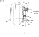
FIG. 3 is an explanatory diagram of an airbag module in a preferred embodiment of the mounting structure for mounting an airbag module to a steering wheel according to the present invention, as viewed from the X-axis direction. -
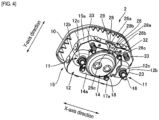
FIG. 4 is an explanatory diagram depicting the back side of the airbag module depicted inFIG. 3 . -
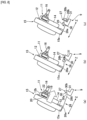
FIG. 5 is an exploded perspective view of the airbag module depicted inFIG. 3 . -
FIG. 6 is an enlarged perspective view of an engaging member provided with an insulating member, which is provided in the airbag module depicted inFIG. 3 . -
FIG. 7 is a schematic explanatory diagram (as viewed from the direction of line A-A inFIG. 2 ) depicting an initial state of attachment of a preferred embodiment of the mounting structure for mounting an airbag module to a steering wheel according to the present invention. -
FIG. 8 is an explanatory diagram illustrating an engagement between an engaging member of the airbag module depicted inFIG. 3 and an engaging protrusion of the core metal. -
FIG. 9 is an enlarged cross-sectional view of a main part depicting an engaged state between an engaging protrusion and an engaging hole provided with an insulating member, which are engaged by the engagement action indicated inFIG. 8 . -
FIG. 10 is a perspective view of a main part depicting a mounting state of the core metal depicted inFIG. 2 and the airbag module depicted inFIG. 3 . - A preferred embodiment of a mounting structure for mounting an airbag module to a steering wheel according to the present invention will be described in detail below with reference to the accompanying drawings.
-
FIG. 1 to FIG. 5 depict asteering wheel 1 for a vehicle and anairbag module 2 attached thereto. -
FIG. 1 is a perspective view depicting an outline of asteering wheel 1 to which anairbag module 2 is attached. - In the following drawings, including in
FIG. 1 , each direction is illustrated assuming that the steering position of thesteering wheel 1 mounted on the vehicle is in a neutral position. - The neutral steering position refers to a position where the steering angle of the
steering wheel 1 is "zero" and the steering front wheels face in a straight line. - In the figure, the direction of the Z axis of the three-dimensional coordinate system is along a steering shaft (not shown), with the direction toward the front wheels being downward and the direction toward the
steering wheel 1 being upward. - Similarly, the direction of the X-axis of the three-dimensional coordinate system is from the 3 o'clock direction (right) to the 9 o'clock direction (left) of an analog clock on a plane perpendicular to the Z-axis, and the direction of the Y-axis is from the 12 o'clock direction (up) to the 6 o'clock direction (down) on the same plane. Otherwise, the side seen from the side of the driver shall be described as the front side and the opposite side as the back side.
- The
steering wheel 1 is installed on the driver's seat of the vehicle, is connected to the steering shaft, and transmits the operating force of the driver to the steering gear and the like. - An
airbag module 2 that functions as a driver's seat airbag in the event of an emergency is provided in the center of thesteering wheel 1. - The
airbag module 2 also functions as a horn switch under normal operation that a driver pushes to cause the horn to sound. - The
airbag module 2 further functions as a module damper for damping vibrations of thesteering wheel 1. - The base portion of the
steering wheel 1 is made of acore metal 3 produced by casting. - The
core metal 3 is roughly configured to include aboss area 5 having acentral boss hole 4, arim 6 that is gripped by the driver, andspokes boss area 5 and therim 6. A steering shaft is connected to theboss hole 4. - As depicted in
FIG. 2 , in theboss area 5, when thesteering wheel 1 is in the neutral position, abridge part 9 is provided that connects the base parts of the left andright spokes 7 and is spaced a distance from theboss hole 4 on the 6 o'clock side, which is downward in the vertical direction (Y-axis direction). - The structure of the
airbag module 2 will now be briefly described with reference toFIG. 1 andFIG. 3 toFIG. 5 . Theairbag module 2 on the driver side is covered with ahorn cover 10 made of resin which functions as a design surface. - At the rear of the
horn cover 10, alocking plate 12 is provided to which adamper unit 11, which will be described later, is fixed. - An
airbag cushion 13 that expands and deploys in an emergency is folded to be accommodated inside thehorn cover 10. - An
inflator 14 is attached to thelocking plate 12 and is stowed in theairbag cushion 13. - When a signal is sent from the vehicle sensors during an emergency, inflator gas is supplied from
inflator 14 to theairbag cushion 13. - The
airbag cushion 13 to which the inflation gas is supplied ruptures thehorn cover 10 and expands and deploys into the vehicle interior space to restrain and protect the driver. - The
airbag module 2 is composed of ametal locking plate 12, ametal housing 15 formed in a dish shape with aperipheral wall 15a provided on the surface side and provided in two layers on the surface of thelocking plate 12, two hollowcylindrical damper units 11, apin 16 slidably inserted into the hollow interior of thedamper unit 11, aninflator 14, ametal retainer ring 17 having abolt 17a to which anut 18 is fastened and which fixes theairbag cushion 13, theinflator 14, and the like to thehousing 15, and thehorn cover 10 which stows theairbag cushion 13. - Although not depicted, the
airbag cushion 13 has an insertion hole formed therein into which theinflator 14 is inserted. A bolt insertion hole for theretainer ring 17 is formed around the insertion hole. - The
retainer ring 17 is provided inside theairbag cushion 13. Theretainer ring 17 is aligned with the insertion hole of theairbag cushion 13 so that thebolt 17a projects from the bolt insertion hole. - The
locking plate 12 has ahole part 12a formed in the center thereof, through which theinflator 14 is inserted. Twolock holes 12c for mounting and securing the twodamper units 11 are formed in therecess part 12b on both sides of thehole part 12a. - A
hole part 15b is formed inside aperipheral wall 15a of the dish-shaped housing 15, into which theinflator 14 inserted into thehole part 12a of thelocking plate 12 is inserted. - The
airbag cushion 13 is installed in thehousing 15 with the insertion hole aligned with thehole part 15b. The periphery of the insertion hole of theairbag cushion 13 is sandwiched between theretainer ring 17 and thehousing 15. - The
damper unit 11 is attached to the inside of therecess part 12b from the front side (housing 15 side) of the lockingplate 12, and is secured to the lockingplate 12 via thelock hole 12c. - The
pin 16 has ahead part 16a at one end, and is inserted into thedamper unit 11 from thehousing 15 side and passes through thelock hole 12c of the lockingplate 12. - The
head part 16a of thepin 16 is sandwiched between thehousing 15 and the lockingplate 12 and is retained therebetween. - The inflator 14 has an outer
peripheral flange 14a that abuts against the rear surface of the lockingplate 12. - The inflator 14 is inserted into the insertion hole of the
airbag cushion 13 through thehole part 12a of the lockingplate 12, thehole part 15b of thehousing 15, and theretainer ring 17. - The
bolt 17a of theretainer ring 17 protruding from theairbag cushion 13 passes through thehousing 15, the lockingplate 12, and the outerperipheral flange 14a of the inflator 14, and is fastened to thenut 18 on the back side of the lockingplate 12. - As a result, the
airbag cushion 18 and the inflator 14 are secured to thehousing 15, and thedamper unit 11 is assembled onto the lockingplate 12. - As depicted in
FIG. 5 andFIG. 7 , thehorn cover 10 has anengaging part 10a at an opening edge part that is engaged with anengaged part 15c formed on theperipheral wall 15a of thehousing 15. - When the locking
plate 12 is attached to thehousing 15, theengaging part 10a of thehorn cover 10 is further sandwiched and retained between thepressing part 12d of the lockingplate 12 and theengaged part 15c of the housing 15 (seeFIG. 7 ). - The
damper unit 11 provided in theairbag module 2 is a member for elastically mounting theairbag module 2 to thecore metal 3 of thesteering wheel 1, and forms the center of the module damper. - Briefly, as depicted in
FIG. 5 , thedamper unit 11 is configured by housing a ring-shapedelastic body 19 for damping vibration inside aholder 20, and engaging aninsulator plate 21 superimposed on one end of theelastic body 19 with asleeve 22 that is inserted into and retained within theelastic body 19. Thepin 16 is inserted into asleeve 22. - The
holder 20 is inserted into thelock hole 12c of the lockingplate 12 and secured to the lockingplate 12 by being rotated relative to thelock hole 12c. - As depicted in
FIG. 2 , the twodamper units 11 are arranged side by side in the X-axis direction with the neutral position of thesteering wheel 1 as a reference, and are disposed on both the left and right sides of theairbag module 2. - As depicted in
FIG. 3 , apin 16 protrudes from thedamper unit 11 in the Z-axis direction toward theboss area 5 of thecore bar 3. - By attaching this
pin 16 to thecore metal 3, theairbag module 2 is attached and connected to thesteering wheel 1 in the Z-axis direction via thedamper unit 11. - As a result, a
damper unit 11 for damping vibrations of thesteering wheel 1 is disposed between theairbag module 2 and thesteering wheel 1. - The
pin 16 is inserted through a coil-shapedhorn spring 23 and then into acollar member 24 provided on thecore bar 3. Thepin 16 is attached to and retained by thecore bar 3 with a collar member 24 (seeFIG. 7 ). - That is, the
horn spring 23 is provided between thecore metal 3 and theairbag module 2, and ensures a gap between thecore metal 3 and theairbag module 2 for operating the horn. - As a result, the
airbag module 2 is elastically supported by thehorn spring 23 relative to thesteering wheel 1 and is connected to thedamper unit 11 so as to be movable toward thesteering wheel 1, in other words, is capable of being pressed. - The vibration of the
steering wheel 1 is transmitted to thedamper unit 11 via thepin 16. The transmitted vibrations act as a damper mass using theairbag module 2 and are damped by theelastic body 19 of thedamper unit 11. - In the present embodiment, in order to achieve vibration damping by the
damper units 11 provided at two locations on theairbag module 2, the hardness of theelastic body 19 is preferably increased, and the Shore A rubber hardness is preferably set to HS18 to HS80. - Regarding the horn function, when the
airbag module 2 is pressed in the Z-axis direction toward thesteering wheel 1, theentire airbag module 2 including thedamper unit 11 slides against thepin 16 retained by thecollar member 24 of thecore metal 3, and thehorn spring 23 is elastically compressed and deformed. - As a result, the contacts provided on the
housing 15 of theairbag module 2 and thecore metal 3 are electrically connected, causing the horn to sound. - When pressing of the
airbag module 2 is lifted, thehorn spring 23 is elastically restored such that theairbag module 2 is retracted, and thereby the contact points are separated from each other such that sounding is stopped. - Therefore, the
housing 15 of theairbag module 2 and thecore metal 3 of thesteering wheel 1 form a conductive circuit. - In order to reliably activate the horn, it is preferable that an embossment (not shown) be provided on the outside edge of the
housing 15 as the contact point on theairbag module 2 side, and acopper rivet 25 be provided on thecore metal 3 as the contact point on thesteering wheel 1 side, as depicted inFIG. 2 . - Further, in the present embodiment, as a configuration for attaching the
airbag module 2 to thesteering wheel 1 in the Z-axis direction, an engagingmember 26 is provided on thehousing 15 and an engagingprotrusion 27 is provided on thecore 3, as depicted inFIG. 6 to FIG. 10 . - The engaging
member 26 is provided between thesteering wheel 1 and theairbag module 2 in parallel with thedamper unit 11 described above. - As depicted in
FIG. 6 andFIG. 8 , the engagingmember 26 is formed of a plate material that is elastically deformable in the direction of the thickness thereof. - The engaging
member 26 has abase end 26a, which is a first end in the longitudinal direction, joined to theperipheral wall 15a of thehousing 15, and is thereby provided on theairbag module 2 side. - An engaging
hole 28 is formed in the engagingmember 26 at atip end 26b side, which is the other end in the length direction, so as to penetrate therethrough in the plate thickness direction. In the illustrated example, the engaginghole 28 is formed in a substantially rectangular shape in the longitudinal direction of the engagingmember 26. - A pair of left and
right ribs 26c are provided on thetip end 26b side of the engagingmember 26 and are bent toward thehousing 15 side so as to sandwich the engaginghole 28 from both sides in the width direction of the engagingmember 26. - As a material used for the engaging
member 26, stainless steel is most preferable in terms of a balance of elasticity, strength, and cost, and of these,SUS301 CSP 3/4H t0.6 is most preferable. - The
base end 26a of the engagingmember 26 is joined to theperipheral wall 15a of thehousing 15 byrivets 29 at two locations in the width direction of the engagingmember 26 in order to ensure high rigidity against the tensile load generated between theairbag module 1 and theairbag module 2. - The engaging
protrusion 27 is integrally provided on thebridge part 9 of theboss area 5 formed by thecore metal 3 of thesteering wheel 1 so as to protrude from thebridge part 9. - The engaging
protrusion 27 is formed so as to protrude upward from a position on the lower side of thesteering wheel 1 in the vertical direction, in other words, from thebridge part 9 on the 6 o'clock side which is below theboss hole 4, based on the neutral position of thesteering wheel 1, toward theboss hole 4 which is the center of thesteering wheel 1. As a result, the engagingprotrusion 27 is positioned between thebridge part 9 and theboss hole 4. - As depicted in
FIG. 2 andFIG. 7 , the engagingprotrusion 27 is formed by aninclined surface 30 that appears on the front side of thebridge part 9 in the Z-axis direction, with the bridge part 9 (front side) as thestarting point 30a and extending diagonally upward toward theboss hole 4. - The surface of the engaging
protrusion 27 that appears on the back side of thebridge part 9 is a flatengaging surface 31 that extends downward from the end edge 30bb of theinclined surface 30 to the back side of thebridge part 9. That is, the engagingprotrusion 27 is formed in a substantially right-angled triangle shape when viewed from the X-axis direction. - The
inclined surface 30 is formed toward the Z-axis direction, which is the mounting direction of theairbag module 2 to thesteering wheel 1. - As depicted in
FIG. 7 andFIG. 8 , thetip end 26b of the engagingmember 26 is slid on theinclined surface 30. - The width dimension of the engaging
protrusion 27 in the X-axis direction is set so as to enable insertion thereof into the engaginghole 28 of the engagingmember 26. - When the
tip end 26b side of the engagingmember 26 slides along theinclined surface 30, the rectangular engaginghole 28 has aleading edge 28a close to thetip end 26b of the engagingmember 26 that moves first, and a trailingedge 28b closer to thebase end 26a of the engagingmember 26 that moves second. - When the
airbag module 2 is attached to thesteering wheel 1 in the Z-axis direction, thetip end 26b of the engagingmember 26 is first positioned on thestarting point 30a side of theinclined surface 30, as depicted inFIG. 8(a) . - When the
airbag module 2 is subsequently pressed toward thesteering wheel 1, as shown inFIG. 8(b) , thetip end 26b of the engagingmember 26 slides along theinclined surface 30 and is displaced toward theboss hole 4, so that the engagingmember 26 is elastically bent and deformed. - As depicted in
FIG. 8C , when theleading edge 28a of the engaginghole 28 reaches theend edge 30b and passes over theend edge 30b of theinclined surface 30, the engagingmember 26 elastically returns to its original shape, and the engagingprotrusion 27 is inserted into the engaginghole 28. - Then, as depicted in
FIG. 9 andFIG. 10 , theleading edge 28a of the engaginghole 28 into which the engagingprotrusion 27 is inserted is engaged with the engagingsurface 31 of the engagingprotrusion 27. - As a result, the engaging
protrusion 27 and the engaginghole 28 are engaged with each other, and theairbag module 2 is attached to thecore metal 3 of thesteering wheel 1. - The
inclined surface 30 allows the engagingmember 26 to be smoothly bent and elastically deformed. - The
core metal 3 of thesteering wheel 1 having thespokes bridge part 9, and theboss area 5 including the engagingprotrusion 27 are formed by pouring metal into a casting mold which is divided by a parting line P. - As depicted in
FIG. 7 , the parting line P is set to cross theinclined surface 30 so as to prevent burrs or chips from being formed on the upper and lower ends of the engagingprotrusion 27. - The
inclined surface 30 may be polished or otherwise treated to make the inclined surface more slippery. In this manner, even if the parting line P remains, elastic deformation of the engagingmember 26 can be smooth. - This prevents the engaging
member 26 from being impeded in assembling with the engagingprotrusion 27 and prevents the engagingmember 26 from being damaged, thereby enabling smooth assembly. - Between the engaging
protrusion 27 and the engaginghole 28, an insulatingmember 32 is provided as a covering material to prevent contact between the engagingprotrusion 27 and the engaginghole 28 engaged with the engagingprotrusion 27, thereby insulating them from electrical conduction. In the present embodiment, the insulatingmember 32 is provided on an engagingmember 26 having an engaginghole 28. - The insulating
member 32 is formed out of a non-conductive material such as a synthetic resin material. The insulatingmember 32 is provided to match the position of therib 26c of the engagingmember 26. - As depicted in
FIG. 6 andFIG. 9 , the insulatingmember 32 covers the front and back of the engagingmember 26, including therib 26c, and is mated with a foldedpart 28c of theleading edge 28a of the engaginghole 28 that engages with the engagingsurface 31 of the engagingprotrusion 27, thereby covering theleading edge 28a. - Therefore, the trailing
edge 28b side of the engaginghole 28 may or may not be covered by the insulatingmember 32. -
FIG. 9 depicts the state in which the engaginghole 28 is engaged with the engagingprotrusion 27. An insulatingmember 32 provided on thefront edge 28a of the engaginghole 28 including therib 26c and the foldedpart 28c is engaged with the engagingsurface 31 of the engagingprotrusion 27. - Therefore, the insulating
member 32 can ensure noise reduction, wear resistance, and impact resistance at the engaging portions in all X, Y, and Z axis directions at low cost. - In the Z-axis direction, the
airbag module 2 is provided on thecore metal 3 of thesteering wheel 1 and receives the elasticity effect of thehorn spring 23. - Therefore, only the
front edge 28a of the engaginghole 28 of the engagingmember 26 on theairbag module 2 side is engaged with the engagingsurface 31 of the engagingprotrusion 27 of thecore metal 3. - As a result, only the
front edge 28a of the engaginghole 28 and the vicinity are insulated from the engagingprotrusion 27, thereby cutting off electrical conduction between thecore metal 3 and thehousing 15 of theairbag module 2. - In the present embodiment, as depicted in
FIG. 4 , the lockingplate 12 of theairbag module 2 is provided with a pair of coil springs 33 on both sides of the engagingmember 26 in the X-axis direction via bushings 34 (seeFIG. 5 ). - These coil springs 33 ensure a support structure from the
core 3 side of theairbag module 2 around the engagingmember 26 located on the 6 o'clock side, in other words, stable support of theairbag module 2 when the horn is not operated, and favorable press operability of theairbag module 2 when the horn is operated. - Operation of the mounting structure of the
airbag module 2 to thesteering wheel 1 according to the present embodiment will be described with reference toFIG. 7 to FIG. 10 . - When attaching the
airbag module 2 to thesteering wheel 1, as depicted inFIG. 7 , thepin 16 inserted into thedamper unit 11 is brought into contact with thecollar member 24 near theboss hole 4 of thecore bar 3 in the Z-axis direction, and thetip end 26b of the engagingmember 26 provided with the insulatingmember 32 is abutted against thestarting point 30a of theinclined surface 30 of the engagingprotrusion 27. - Next, as depicted in
FIG. 8 , theairbag module 2 is pressed in the Z-axis direction toward thecore metal 3, and the engagingmember 26 is caused to move along theinclined surface 30 of the engagingprotrusion 27, thereby undergoing bending elastic deformation. - Finally, the engaging
protrusion 27 is inserted into the engaginghole 28 by the elastic restoring action of the engagingmember 26. - When the engaging
protrusion 27 is inserted into the engaginghole 28, as depicted inFIG. 9 , the insulatingmember 32 abuts against the engagingsurface 31 of the engagingprotrusion 27, and thecore 3 and theairbag module 2 including the engagingmember 26 are engaged in an electrically insulated state. - As a result, as shown in
Figure 10 , the engagingmember 26 joined to thehousing 15 of theairbag module 2 surrounds the engagingprotrusion 27 with theleading edge 28a of the engaginghole 28 engaging with the engagingsurface 31 of the engagingprotrusion 27, and theairbag module 2 is attached to thecore 3 of thesteering wheel 1. - Almost simultaneously with this attachment, the
damper unit 11 is coupled to thecollar member 24 of theboss area 5 via thepin 16, completing the connection between theairbag module 2 and thesteering wheel 1 via thedamper unit 11. - In the mounting structure for mounting an airbag module to a steering wheel according to the present embodiment, the mounting is performed by inserting the engaging
protrusion 27 into the engaginghole 28, that is, by the engaging action in which the engagingprotrusion 27 is surrounded by the engaginghole 28. - Therefore, when attaching the
airbag module 2, which transmits vibrations, to thesteering wheel 1, the engaging portions between the engagingmembers 26 and the engagingprotrusions 27 can ensure a reliable attachment without any rattling in any direction in the X, Y, and Z axial directions. - The engaging
member 26 is provided with an insulatingmember 32 that covers theleading edge 28a and surrounding area of the engaginghole 28. This ensures electrical insulation between the engagingmember 26 provided on thehousing 15 and thecore metal 3 on which the engagingprotrusion 27 is formed, allowing the horn to operate properly. - Furthermore, by inserting the engaging
protrusion 27 into the engaginghole 28 and by providing the insulatingmember 32 in the engaginghole 28, noise reduction, wear resistance, and impact resistance at the engaging portion can be ensured. - When the
airbag module 2 is mounted to thesteering wheel 1, the engagingmember 26 is elastically bent and deformed by theinclined surface 30 of the engagingprotrusion 27. - Therefore, the engaging
protrusion 27 and the engaginghole 28 can be engaged simply by pressing theairbag module 2, making the installation operation extremely simple and providing superior assembly workability. - The structure for mounting an airbag module to a steering wheel described above is a preferred example of the present invention, but other embodiments can be implemented or performed in various ways. In particular, unless otherwise described in the specification of the application, the invention is not restricted to the shapes, sizes, configurational dispositions, and the like of the parts illustrated in detail in the accompanying drawings. In addition, the expressions and terms used in the specification of the application are used for providing a description, without limiting the invention thereto, unless specifically described otherwise.
- The mounting structure for mounting the
airbag module 2 to thesteering wheel 1 includes: an engagingmember 26, the base end side being joined to thehousing 15 of theairbag module 2, having an engaginghole 28 at the tip end thereof; an engagingprotrusion 27 formed on thecore 3 of thesteering wheel 1 so as to protrude upward from a vertical lower position of thesteering wheel 1 toward the center of thesteering wheel 1, with the neutral position of thesteering wheel 1 as a reference, and which is inserted into the engaginghole 28 of the engagingmember 26 to mount theairbag module 2 to thesteering wheel 1; and an insulatingmember 32 provided between the engagingprotrusion 27 and the engaginghole 28 for preventing contact between the engagingprotrusion 27 and the engaginghole 28 engaged with the engagingprotrusion 27. - In the mounting structure for mounting the
airbag module 2 to thesteering wheel 1 described inAddendum 1, the engagingmember 26 is formed of a plate material having an engaginghole 28 formed therethrough and capable of bending elastically deforming, and the engagingprotrusion 27 is formed with aninclined surface 30 along which thetip end 26b of the engagingmember 26 slides along the mounting direction of theairbag module 2 mounting to thesteering wheel 1, the engagingmember 26 slides along theinclined surface 30 and undergoes bending elastic deformation, and when the engaginghole 28 reaches theend edge 30b of theinclined surface 30, the engagingmember 26 elastically restores its original shape, and the engagingprotrusion 27 may be inserted into the engaginghole 28. - In the mounting structure for mounting the
airbag module 2 to thesteering wheel 1 described inAddendum 1, thecore metal 3 of thesteering wheel 1 is formed by a casting mold which is molded at a parting line P, and the parting line P is set so as to cross theinclined surface 30. - In the mounting structure for mounting the
airbag module 2 to thesteering wheel 1 described in any one ofAddendums 1 to 3, thehousing 15 of theairbag module 2 and thecore metal 3 of thesteering wheel 1 may form a conductive circuit. - In the mounting structure for mounting the
airbag module 2 to thesteering wheel 1 described in any one ofAddendums 1 to 4, theairbag module 2 is a damper mass, and adamper unit 11 for damping vibrations of thesteering wheel 1 may be provided between thesteering wheel 1 and theairbag module 2 in parallel with the engagingmember 26. -
- 1. Steering wheel
- 2. Airbag module
- 3. Core metal
- 11. Damper unit
- 15. Housing
- 26. Engaging member
- 26a. Base end of engaging member
- 26b. Tip end of engaging member
- 27. Engaging protrusion
- 28. Engaging hole
- 30. Inclined surface
- 30b. End edge of inclined surface
- 32. Insulating member
- P. Parting line
Claims (5)
- A mounting structure for mounting an airbag module to steering wheel comprising:an engaging member, a base end side being joined to housing of the airbag module, having an engaging hole at the tip end thereof;an engaging protrusion formed on a core of the steering wheel so as to protrude upward from a vertical lower position of the steering wheel toward the center of the steering wheel, with the neutral position of the steering wheel as a reference, and which is inserted into an engaging hole of the engaging member to mount the airbag module to the steering wheel; andan insulating member provided between the engaging protrusion and the engaging hole for preventing contact between the engaging protrusion and the engaging hole engaged with the engaging protrusion.
- The mounting structure for mounting the airbag module to the steering wheel according to claim 1, whereinthe engaging member is formed of a plate material having the engaging hole formed therethrough and capable of bending elastically deforming,the engaging protrusion is formed with an inclined surface along which a tip end of the engaging member slides along the mounting direction of the airbag module mounting to the steering wheel,the engaging member slides along the inclined surface and undergoes bending elastic deformation, andwhen the engaging hole reaches an end edge of the inclined surface, the engaging member elastically restores the original shape thereof and the engaging protrusion is inserted into the engaging hole.
- The mounting structure for mounting the airbag module to the steering wheel according to claim 2, wherein the core metal of the steering wheel is formed by a casting mold which is molded at a parting line, and the parting line is set so as to cross the inclined surface.
- The mounting structure for mounting the airbag module to the steering wheel according to any one of claims 1 to 3, wherein the housing of the airbag module and the core metal of the steering wheel form a conductive circuit.
- The mounting structure for mounting the airbag module to the steering wheel according to any one of claims 1 to 3, wherein the airbag module is a damper mass, and a damper unit for damping vibrations of the steering wheel is provided between the steering wheel and the airbag module in parallel with the engaging member.
Applications Claiming Priority (2)
| Application Number | Priority Date | Filing Date | Title |
|---|---|---|---|
| JP2022134071 | 2022-08-25 | ||
| PCT/JP2023/028374 WO2024043027A1 (en) | 2022-08-25 | 2023-08-03 | Structure for attaching airbag module to steering wheel |
Publications (2)
| Publication Number | Publication Date |
|---|---|
| EP4559780A1 true EP4559780A1 (en) | 2025-05-28 |
| EP4559780A4 EP4559780A4 (en) | 2026-01-07 |
Family
ID=90013077
Family Applications (1)
| Application Number | Title | Priority Date | Filing Date |
|---|---|---|---|
| EP23857141.8A Pending EP4559780A4 (en) | 2022-08-25 | 2023-08-03 | STRUCTURE FOR MOUNTING AN AIRBAG MODULE TO A STEERING WHEEL |
Country Status (4)
| Country | Link |
|---|---|
| EP (1) | EP4559780A4 (en) |
| JP (1) | JP7846772B2 (en) |
| CN (1) | CN119654271A (en) |
| WO (1) | WO2024043027A1 (en) |
Family Cites Families (6)
| Publication number | Priority date | Publication date | Assignee | Title |
|---|---|---|---|---|
| DE19927032A1 (en) * | 1999-06-04 | 2000-12-14 | Petri Ag | Arrangement for locking an airbag module with a steering wheel |
| JP2001088648A (en) * | 1999-09-24 | 2001-04-03 | Nippon Plast Co Ltd | Steering wheel |
| JP2001199300A (en) * | 2000-01-17 | 2001-07-24 | Hosei Brake Ind Ltd | Steering wheel structure |
| JP2005059033A (en) * | 2003-08-08 | 2005-03-10 | Nippon Plast Co Ltd | Mold and method for forming steering wheel core metal |
| JP6905548B2 (en) | 2018-07-11 | 2021-07-21 | オートリブ ディベロップメント エービー | Steering wheel damper mechanism and vehicle steering wheel device |
| CN114845926B (en) * | 2020-01-16 | 2023-10-13 | 奥托立夫开发公司 | Steering wheel device for vehicle |
-
2023
- 2023-08-03 CN CN202380057839.6A patent/CN119654271A/en active Pending
- 2023-08-03 EP EP23857141.8A patent/EP4559780A4/en active Pending
- 2023-08-03 WO PCT/JP2023/028374 patent/WO2024043027A1/en not_active Ceased
- 2023-08-03 JP JP2024542712A patent/JP7846772B2/en active Active
Also Published As
| Publication number | Publication date |
|---|---|
| JPWO2024043027A1 (en) | 2024-02-29 |
| EP4559780A4 (en) | 2026-01-07 |
| CN119654271A (en) | 2025-03-18 |
| JP7846772B2 (en) | 2026-04-15 |
| WO2024043027A1 (en) | 2024-02-29 |
Similar Documents
| Publication | Publication Date | Title |
|---|---|---|
| US11034374B2 (en) | Steering wheel | |
| EP3812240B1 (en) | Structure for mounting and fixing damper unit in steering wheel, and steering wheel | |
| KR102610029B1 (en) | steering wheel | |
| CN102442269B (en) | Steering wheel with airbag installed | |
| JP3566693B2 (en) | Steering wheel | |
| US12612104B2 (en) | Steering wheel device for vehicle | |
| CN104925016B (en) | Steering wheel | |
| US11529921B2 (en) | Steering wheel | |
| US6908102B2 (en) | Airbag apparatus | |
| US12522275B2 (en) | Steering wheel and method of manufacturing same | |
| CN110116749B (en) | Steering wheel assembly for motor vehicle, method for assembling steering wheel assembly and structural assembly | |
| EP4365059A1 (en) | Steering wheel device for vehicle | |
| KR20190130051A (en) | How to connect the airbag module, steering wheel and airbag module to the steering wheel | |
| US6501035B2 (en) | Switching unit for steering wheel in motor vehicle | |
| JP7846772B2 (en) | Airbag module mounting structure to the steering wheel | |
| US7316414B2 (en) | Housing for an airbag module | |
| JPH08318806A (en) | Airbag module for driver's seat | |
| US20260138663A1 (en) | Vehicle steering wheel device | |
| EP4566914A1 (en) | Vehicle steering wheel device | |
| EP4538125A1 (en) | Airbag device provided to steering wheel | |
| JP4018846B2 (en) | Steering wheel | |
| EP4378795A1 (en) | Steering wheel | |
| US12358452B1 (en) | Airbag fastening structure | |
| JP7286218B2 (en) | Fixing structure for damper unit in steering wheel and steering wheel device for vehicle | |
| KR100542590B1 (en) | Car horn |
Legal Events
| Date | Code | Title | Description |
|---|---|---|---|
| STAA | Information on the status of an ep patent application or granted ep patent |
Free format text: STATUS: THE INTERNATIONAL PUBLICATION HAS BEEN MADE |
|
| PUAI | Public reference made under article 153(3) epc to a published international application that has entered the european phase |
Free format text: ORIGINAL CODE: 0009012 |
|
| STAA | Information on the status of an ep patent application or granted ep patent |
Free format text: STATUS: REQUEST FOR EXAMINATION WAS MADE |
|
| 17P | Request for examination filed |
Effective date: 20250219 |
|
| AK | Designated contracting states |
Kind code of ref document: A1 Designated state(s): AL AT BE BG CH CY CZ DE DK EE ES FI FR GB GR HR HU IE IS IT LI LT LU LV MC ME MK MT NL NO PL PT RO RS SE SI SK SM TR |
|
| DAV | Request for validation of the european patent (deleted) | ||
| DAX | Request for extension of the european patent (deleted) | ||
| A4 | Supplementary search report drawn up and despatched |
Effective date: 20251210 |
|
| RIC1 | Information provided on ipc code assigned before grant |
Ipc: B62D 1/04 20060101AFI20251204BHEP Ipc: B60R 21/203 20060101ALI20251204BHEP |