EP4559609A1 - Water supplying device and control method for water supplying device - Google Patents
Water supplying device and control method for water supplying device Download PDFInfo
- Publication number
- EP4559609A1 EP4559609A1 EP22958700.1A EP22958700A EP4559609A1 EP 4559609 A1 EP4559609 A1 EP 4559609A1 EP 22958700 A EP22958700 A EP 22958700A EP 4559609 A1 EP4559609 A1 EP 4559609A1
- Authority
- EP
- European Patent Office
- Prior art keywords
- valve
- liquid level
- water supply
- water
- resistivity value
- Prior art date
- Legal status (The legal status is an assumption and is not a legal conclusion. Google has not performed a legal analysis and makes no representation as to the accuracy of the status listed.)
- Pending
Links
Images




Classifications
-
- B—PERFORMING OPERATIONS; TRANSPORTING
- B23—MACHINE TOOLS; METAL-WORKING NOT OTHERWISE PROVIDED FOR
- B23H—WORKING OF METAL BY THE ACTION OF A HIGH CONCENTRATION OF ELECTRIC CURRENT ON A WORKPIECE USING AN ELECTRODE WHICH TAKES THE PLACE OF A TOOL; SUCH WORKING COMBINED WITH OTHER FORMS OF WORKING OF METAL
- B23H1/00—Electrical discharge machining, i.e. removing metal with a series of rapidly recurring electrical discharges between an electrode and a workpiece in the presence of a fluid dielectric
- B23H1/10—Supply or regeneration of working media
-
- C—CHEMISTRY; METALLURGY
- C02—TREATMENT OF WATER, WASTE WATER, SEWAGE, OR SLUDGE
- C02F—TREATMENT OF WATER, WASTE WATER, SEWAGE, OR SLUDGE
- C02F1/00—Treatment of water, waste water, or sewage
- C02F1/001—Processes for the treatment of water whereby the filtration technique is of importance
-
- C—CHEMISTRY; METALLURGY
- C02—TREATMENT OF WATER, WASTE WATER, SEWAGE, OR SLUDGE
- C02F—TREATMENT OF WATER, WASTE WATER, SEWAGE, OR SLUDGE
- C02F1/00—Treatment of water, waste water, or sewage
- C02F1/008—Control or steering systems not provided for elsewhere in subclass C02F
-
- C—CHEMISTRY; METALLURGY
- C02—TREATMENT OF WATER, WASTE WATER, SEWAGE, OR SLUDGE
- C02F—TREATMENT OF WATER, WASTE WATER, SEWAGE, OR SLUDGE
- C02F1/00—Treatment of water, waste water, or sewage
- C02F1/42—Treatment of water, waste water, or sewage by ion-exchange
-
- C—CHEMISTRY; METALLURGY
- C02—TREATMENT OF WATER, WASTE WATER, SEWAGE, OR SLUDGE
- C02F—TREATMENT OF WATER, WASTE WATER, SEWAGE, OR SLUDGE
- C02F2103/00—Nature of the water, waste water, sewage or sludge to be treated
- C02F2103/16—Nature of the water, waste water, sewage or sludge to be treated from metallurgical processes, i.e. from the production, refining or treatment of metals, e.g. galvanic wastes
-
- C—CHEMISTRY; METALLURGY
- C02—TREATMENT OF WATER, WASTE WATER, SEWAGE, OR SLUDGE
- C02F—TREATMENT OF WATER, WASTE WATER, SEWAGE, OR SLUDGE
- C02F2201/00—Apparatus for treatment of water, waste water or sewage
- C02F2201/002—Construction details of the apparatus
- C02F2201/005—Valves
-
- C—CHEMISTRY; METALLURGY
- C02—TREATMENT OF WATER, WASTE WATER, SEWAGE, OR SLUDGE
- C02F—TREATMENT OF WATER, WASTE WATER, SEWAGE, OR SLUDGE
- C02F2209/00—Controlling or monitoring parameters in water treatment
- C02F2209/005—Processes using a programmable logic controller [PLC]
-
- C—CHEMISTRY; METALLURGY
- C02—TREATMENT OF WATER, WASTE WATER, SEWAGE, OR SLUDGE
- C02F—TREATMENT OF WATER, WASTE WATER, SEWAGE, OR SLUDGE
- C02F2209/00—Controlling or monitoring parameters in water treatment
- C02F2209/05—Conductivity or salinity
-
- C—CHEMISTRY; METALLURGY
- C02—TREATMENT OF WATER, WASTE WATER, SEWAGE, OR SLUDGE
- C02F—TREATMENT OF WATER, WASTE WATER, SEWAGE, OR SLUDGE
- C02F2209/00—Controlling or monitoring parameters in water treatment
- C02F2209/42—Liquid level
-
- C—CHEMISTRY; METALLURGY
- C02—TREATMENT OF WATER, WASTE WATER, SEWAGE, OR SLUDGE
- C02F—TREATMENT OF WATER, WASTE WATER, SEWAGE, OR SLUDGE
- C02F2209/00—Controlling or monitoring parameters in water treatment
- C02F2209/44—Time
-
- C—CHEMISTRY; METALLURGY
- C02—TREATMENT OF WATER, WASTE WATER, SEWAGE, OR SLUDGE
- C02F—TREATMENT OF WATER, WASTE WATER, SEWAGE, OR SLUDGE
- C02F2301/00—General aspects of water treatment
- C02F2301/04—Flow arrangements
- C02F2301/046—Recirculation with an external loop
Definitions
- the present disclosure relates to a water supply device (water supplying device) and a control method for a water supply device (water supplying device).
- JP H05-002816 U discloses a working fluid supply device for a wire electric discharge machine.
- the working fluid supply device automatically supplies tap water when the working fluid in the wire electric discharge machine decreases.
- a first aspect of the present disclosure is characterized by a water supply device for automatically supplying water to an electric discharge machine, the water supply device including: a first water supply path configured to supply water from an outside of the electric discharge machine to at least one of a clean water tank, a sewage tank, or a work pan of the electric discharge machine; a first valve configured to open and close the first water supply path; a second water supply path configured to supply water from the outside of the electric discharge machine to an ion exchange unit including an ion exchange resin provided in the electric discharge machine; a second valve configured to open and close the second water supply path; and a circulation path configured to send a working fluid from the ion exchange unit to the clean water tank.
- a second aspect of the present disclosure is characterized by a method for controlling a water supply device that automatically supplies water to an electric discharge machine, wherein the water supply device includes: a first water supply path configured to supply water from an outside of the electric discharge machine to at least one of a clean water tank, a sewage tank, or a work pan of the electric discharge machine; a first valve configured to open and close the first water supply path; a second water supply path configured to supply water from the outside of the electric discharge machine to an ion exchange unit including an ion exchange resin provided in the electric discharge machine; a second valve configured to open and close the second water supply path; and a circulation path configured to send a working fluid from the ion exchange unit to the clean water tank, the method including: a resistivity value acquisition step of acquiring a resistivity value of the working fluid; a sewage tank liquid level acquisition step of acquiring a liquid level in the sewage tank; a work pan liquid level acquisition step of acquiring a liquid level in the work pan; and a control step of opening and closing
- An object of the present disclosure is to shorten the period of time from when water is added to the working fluid to when electric discharge machining is started.
- the description is given using the resistivity value [ ⁇ m], but the conductivity [S/m] may be used instead of the resistivity value [ ⁇ m].
- the conductivity [S/m] of the working fluid increases.
- the conductivity [S/m] is the reciprocal of the resistivity value [ ⁇ m]. That is, increasing the resistivity value [ ⁇ m] is synonymous with decreasing the conductivity [S/m].
- FIG. 1 is a schematic diagram showing a wire electric discharge machine 10.
- the wire electric discharge machine 10 includes a machine main body 12, a dielectric fluid unit 14, and a water supply device 16.
- the wire electric discharge machine 10 corresponds to an electric discharge machine of the present invention.
- the machine main body 12 includes a work pan 18.
- the machine main body 12 performs electric discharge machining on a workpiece in a state in which the working fluid is stored in the work pan 18.
- the dielectric fluid unit 14 has a sewage tank 20, a clean water tank 22, an ion exchange unit 24, and a dielectric fluid control unit 26.
- the sewage tank 20 is connected to the work pan 18 via a drainage path 28.
- the working fluid is discharged from the work pan 18 to the sewage tank 20.
- the working fluid discharged from the work pan 18 to the sewage tank 20 contains sludge and the like generated during electric discharge machining of the workpiece.
- the sewage tank 20 is connected to the clean water tank 22 via a filtration path 30.
- the filtration path 30 is provided with a first pump 32 and a filter 34.
- the first pump 32 pumps up the working fluid in the sewage tank 20 and sends it to the clean water tank 22.
- the filter 34 filters the working fluid sent from the sewage tank 20 to the clean water tank 22, and removes sludge and the like from the working fluid.
- a sewage tank liquid level measurement unit 36 is provided in the sewage tank 20.
- the sewage tank liquid level measurement unit 36 measures the liquid level of the working fluid stored in the sewage tank 20.
- the work pan 18 is provided with a work pan liquid level measurement unit 37.
- the work pan liquid level measurement unit 37 measures the liquid level of the working fluid stored in the work pan 18.
- the clean water tank 22 is connected to the ion exchange unit 24 via a first circulation path 38 and a second circulation path 40.
- a second pump 42 and a circulation valve 44 are provided in the first circulation path 38.
- the working fluid in the clean water tank 22 is sent to the ion exchange unit 24 through the first circulation path 38.
- the working fluid that has passed through the ion exchange resin inside the ion exchange unit 24 is returned to the clean water tank 22 by the second circulation path 40.
- the second circulation path 40 corresponds to a circulation circuit of the present invention.
- the clean water tank 22 is provided with a resistivity value measurement unit 46.
- the resistivity value measurement unit 46 measures the resistivity value [ ⁇ m] of the working fluid stored in the clean water tank 22.
- the ion exchange unit 24 has an ion exchange resin therein.
- the second pump 42 circulates the working fluid between the clean water tank 22 and the ion exchange unit 24.
- the ion exchange resin exchanges ions contained in the working fluid passing through the ion exchange resin with other ions. This increases the resistivity value [ ⁇ m] of the working fluid.
- the work pan 18 is connected to the clean water tank 22 via a working fluid supply path 48.
- the work pan 18 is supplied with the working fluid whose resistivity value [ ⁇ m] has been adjusted.
- the circulation valve 44 adjusts the amount of working fluid circulating between the clean water tank 22 and the ion exchange unit 24.
- the dielectric fluid control unit 26 controls the circulation valve 44 based on the resistivity value [ ⁇ m] of the working fluid in the clean water tank 22.
- the resistivity value [ ⁇ m] of the working fluid in the clean water tank 22 is maintained at a predetermined value by the dielectric fluid control unit 26 controlling the opening degree or opening time of the circulation valve 44.
- the function of the dielectric fluid control unit 26 may be incorporated into a numerical control device that controls the machine main body 12.
- the water supply device 16 includes a first water supply path 50, a second water supply path 56, and a water supply control unit 60.
- the first water supply path 50 is connected to the clean water tank 22. Tap water is supplied to the clean water tank 22 from the outside of the wire electric discharge machine 10 via the first water supply path 50.
- a first valve 52 is provided in the first water supply path 50. The first valve 52 adjusts the amount of tap water supplied to the clean water tank 22. When tap water is supplied to the clean water tank 22 in a state where the clean water tank 22 is full of the working fluid, the working fluid in the clean water tank 22 flows into the sewage tank 20 over a partition plate 54 between the clean water tank 22 and the sewage tank 20.
- the second water supply path 56 is connected to the ion exchange unit 24. Tap water is supplied to the ion exchange unit 24 from the outside of the wire electric discharge machine 10 via the second water supply path 56.
- the second water supply path 56 is provided with a second valve 58. The second valve 58 adjusts the amount of tap water supplied to the ion exchange unit 24.
- Water supplied from the outside of the wire electric discharge machine 10 is not limited to tap water, and may be groundwater or the like.
- the water supply control unit 60 controls the first valve 52 and the second valve 58 based on the resistivity value [ ⁇ m] of the working fluid in the clean water tank 22 and the liquid level of the sewage tank 20.
- the water supply control process performed by the water supply control unit 60 will be described in detail later.
- the function of the water supply control unit 60 may be incorporated into a numerical control device that controls the machine main body 12.
- FIG. 2 is a block diagram of the water supply control unit 60.
- the water supply control unit 60 includes a computation unit 62 and a storage unit 64.
- the computation unit 62 includes a processor, for example, such as a CPU (Central Processing Unit), a GPU (Graphics Processing Unit), or the like.
- the computation unit 62 includes a resistivity value acquisition unit 66, a sewage tank liquid level acquisition unit 68, a work pan liquid level acquisition unit 69, and a valve control unit 70.
- the resistivity value acquisition unit 66, the sewage tank liquid level acquisition unit 68, the work pan liquid level acquisition unit 69, and the valve control unit 70 are realized by the computation unit 62 executing a program stored in the storage unit 64.
- At least a part of the resistivity value acquisition unit 66, the sewage tank liquid level acquisition unit 68, the work pan liquid level acquisition unit 69, and the valve control unit 70 may be realized by an integrated circuit such as an ASIC (application specific integrated circuit) or a FPGA (field-programmable gate array). At least a part of the resistivity value acquisition unit 66, the sewage tank liquid level acquisition unit 68, the work pan liquid level acquisition unit 69, and the valve control unit 70 may be realized by an electronic circuit including a discrete device.
- ASIC application specific integrated circuit
- FPGA field-programmable gate array
- the storage unit 64 is configured by a volatile memory (not illustrated) and a nonvolatile memory (not illustrated), which are computer-readable storage media.
- the volatile memory is, for example, a RAM (Random Access Memory), or the like.
- the nonvolatile memory for example, is a ROM (Read Only Memory), a flash memory, or the like.
- data and the like are stored in the volatile memory.
- programs, tables, maps, and the like are stored in the nonvolatile memory.
- At least a portion of the storage unit 64 may be provided in the aforementioned processor, integrated circuit, or the like. At least a portion of the storage unit 64 may be mounted on a device connected to the wire electric discharge machine 10 via a network.
- the resistivity value acquisition unit 66 acquires the resistivity value of the working fluid in the clean water tank 22 measured by the resistivity value measurement unit 46.
- the sewage tank liquid level acquisition unit 68 acquires the liquid level in the sewage tank 20 measured by the sewage tank liquid level measurement unit 36.
- the work pan liquid level acquisition unit 69 acquires the liquid level in the work pan 18 measured by the work pan liquid level measurement unit 37.
- the valve control unit 70 controls the first valve 52 and the second valve 58 of the water supply device 16 based on the resistivity value [ ⁇ m] of the working fluid in the clean water tank 22 and the liquid level of the sewage tank 20. As a result, the liquid level of the working fluid in the sewage tank 20 rises. The resistivity value [ ⁇ m] of the working fluid in the clean water tank 22 increases.
- the valve control unit 70 corresponds to the control unit of the present invention.
- FIG. 3 is a flowchart showing a water supply control process executed by the water supply control unit 60.
- the water supply control process is repeatedly executed at regular time intervals.
- step S1 the valve control unit 70 determines whether or not the liquid level in the sewage tank 20 measured by the sewage tank liquid level measurement unit 36 is lower than a predetermined liquid level. If the liquid level is lower than the predetermined liquid level (step S1: YES), the process proceeds to step S2. If the liquid level is equal to or higher than the predetermined liquid level (step S1: NO), the process proceeds to step S5.
- step S2 the valve control unit 70 determines whether or not the resistivity value [ ⁇ m] of the working fluid in the clean water tank 22 measured by the resistivity value measurement unit 46 is less than a threshold. If the resistivity value [ ⁇ m] is less than the threshold (step S2: YES), the process proceeds to step S3. If the resistivity value [ ⁇ m] is equal to or greater than the threshold (step S2: NO), the process proceeds to step S4.
- the threshold may be a value equal to the predetermined value for the resistivity value [ ⁇ m] described above. The threshold may be a value smaller than the predetermined value for the resistivity value [ ⁇ m] described above.
- step S3 the valve control unit 70 controls the first valve 52 to close the first valve 52.
- the valve control unit 70 controls the second valve 58 to open the second valve 58.
- the process returns to step S1. Incidentally, when the first valve 52 is in a closed state before the processing of step S3, the first valve 52 is maintained in the closed state. If the second valve 58 is in an open state before the processing of step S3, the second valve 58 is maintained in the open state.
- step S4 the valve control unit 70 controls the first valve 52 to open the first valve 52.
- the valve control unit 70 controls the second valve 58 to close the second valve 58.
- the process returns to step S1. Incidentally, when the first valve 52 is in an opened state before the processing of step S4, the first valve 52 is maintained in the opened state. If the second valve 58 is in a closed state before the processing of step S4, the second valve 58 is maintained in the closed state.
- step S5 the valve control unit 70 controls the first valve 52 to close the first valve 52.
- the valve control unit 70 controls the second valve 58 to close the second valve 58.
- the water supply control process is ended.
- the first valve 52 is in a closed state before the processing of step S5
- the first valve 52 is maintained in the closed state.
- the second valve 58 is in a closed state before the processing of step S5, the second valve 58 is maintained in the closed state.
- the resistivity value [ ⁇ m] can be increased more quickly than when the working fluid is circulated between the clean water tank 22 and the ion exchange unit 24 while water is being supplied directly to the clean water tank 22.
- the water supply device 16 of the present embodiment includes the second water supply path 56 for supplying water from the outside of the wire electric discharge machine 10 to the ion exchange unit 24, separately from the first water supply path 50 for supplying water from the outside of the wire electric discharge machine 10 to the clean water tank 22.
- the water supply device 16 can shorten the time required to increase the resistivity value [ ⁇ m] of the working fluid to the predetermined value.
- the water supply control unit 60 opens and closes the first valve 52 and the second valve 58 based on the resistivity value [ ⁇ m] of the working fluid and the liquid level in the sewage tank 20.
- the water supply device 16 can increase the resistivity value [ ⁇ m] of the working fluid while raising the liquid level in the sewage tank 20.
- the present embodiment differs from the first embodiment in the content of the water supply control process.
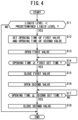
- FIG. 4 is a flowchart showing a water supply control process executed by the water supply control unit 60.
- the water supply control process is repeatedly executed at regular time intervals.
- step S11 the valve control unit 70 determines whether or not the liquid level in the sewage tank 20 measured by the sewage tank liquid level measurement unit 36 is lower than a predetermined liquid level. If the liquid level is lower than the predetermined liquid level (step S11: YES), the process proceeds to step S12. If the liquid level is equal to or higher than the predetermined liquid level (step S11: NO), the water supply control process is terminated.
- step S12 the valve control unit 70 sets the opening time of the first valve 52 based on the resistivity value [ ⁇ m] of the working fluid in the clean water tank 22, the liquid level of the sewage tank 20, and the liquid level of the work pan 18.
- the valve control unit 70 sets the opening time of the second valve 58 based on the resistivity value [ ⁇ m] of the working fluid in the clean water tank 22, the liquid level of the sewage tank 20, and the liquid level of the work pan 18. Thereafter, the process transitions to step S13.
- the opening time of the first valve 52 and the opening time of the second valve 58 are set based on the difference between the total of the amount of the working fluid currently stored in the sewage tank 20 and the amount of the working fluid currently stored in the work pan 18 and the capacity of the sewage tank 20 capable of storing the working fluid.
- the difference may be hereinafter referred to as a required water supply amount.
- the amount of the working fluid currently stored in the sewage tank 20 is obtained from the current liquid level in the sewage tank 20 measured by the sewage tank liquid level measurement unit 36.
- the amount of the working fluid currently stored in the work pan 18 is obtained from the current liquid level in the work pan 18 measured by the work pan liquid level measurement unit 37.
- the opening time of the first valve 52 and the opening time of the second valve 58 are set based on the difference between the resistivity value [ ⁇ m] of water before passing through the ion exchange resin of the ion exchange unit 24 and the resistivity value [ ⁇ m] of the water after passing through the ion exchange resin.
- the difference may be hereinafter referred to as an amount of increase in resistivity value.
- the resistivity value [ ⁇ m] of water before passing through the ion exchange resin of the ion exchange unit 24 and the resistivity value [ ⁇ m] of water after passing through the ion exchange resin are measured in advance.
- the valve control unit 70 sets the opening time of the first valve 52 and the opening time of the second valve 58, based on the required water supply amount and the amount of increase in resistivity value, such that the resistivity value [ ⁇ m] of the working fluid in the clean water tank 22 approaches a predetermined value.
- the set opening time of the first valve 52 may be referred to as a first set time.
- the set opening time of the second valve 58 may be referred to as a second set time.
- step S13 the valve control unit 70 opens the first valve 52. At this time, the second valve 58 is in a closed state. Thereafter, the process transitions to step S14.
- step S14 the valve control unit 70 determines whether or not the time (opening time) during which the first valve 52 is opened is equal to or longer than the first set time.
- the opening time of the first valve 52 is equal to or longer than the first set time (step S14: YES)
- the process proceeds to step S15.
- the opening time of the first valve 52 is less than the first set time (step S14: NO)
- the determination of step S14 is repeated.
- step S15 the valve control unit 70 closes the first valve 52. At this time, the second valve 58 is in a closed state. Thereafter, the process transitions to step S16.
- step S16 the valve control unit 70 opens the second valve 58. At this time, the first valve 52 is in a closed state. Thereafter, the process transitions to step S17.
- step S17 the valve control unit 70 determines whether or not the time (opening time) during which the second valve 58 is opened is equal to or longer than the second set time.
- the opening time of the second valve 58 is equal to or longer than the second set time (step S17: YES)
- the process proceeds to step S18.
- the opening time of the first valve 52 is less than the second set time (step S17: NO)
- the determination of step S17 is repeated.
- step S18 the valve control unit 70 closes the second valve 58. At this time, the first valve 52 is in a closed state. Thereafter, the water supply control process is ended.
- the water supply control unit 60 sets the opening time of the first valve 52 (first set time) and the opening time of the second valve 58 (second set time) based on the resistivity value [ ⁇ m] of the working fluid in the clean water tank 22 and the liquid level of the sewage tank 20.
- the water supply control unit 60 controls the first valve 52 and the second valve 58 to open the first valve 52 and close the second valve 58. Thereafter, when the first set time has elapsed, the water supply control unit 60 closes the first valve 52 and opens the second valve 58. Thereafter, when the second set time has elapsed, the water supply control unit 60 closes the second valve 58.
- the water supply device 16 can increase the resistivity value [ ⁇ m] of the working fluid while raising the liquid level in the sewage tank 20.
- the present embodiment differs from the first embodiment in the content of the water supply control process.
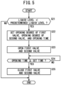
- FIG. 5 is a flowchart showing the water supply control process executed by the water supply control unit 60.
- the water supply control process is repeatedly executed at regular time intervals.
- step S21 the valve control unit 70 determines whether or not the liquid level in the sewage tank 20 measured by the sewage tank liquid level measurement unit 36 is lower than a predetermined liquid level. If the liquid level is lower than the predetermined liquid level (step S21: YES), the process proceeds to step S22. If the liquid level is equal to or higher than the predetermined liquid level (step S21: NO), the water supply control process is terminated.
- step S22 the valve control unit 70 sets the opening degree of the first valve 52 based on the resistivity value [ ⁇ m] of the working fluid in the clean water tank 22, the liquid level of the sewage tank 20, and the liquid level of the work pan 18.
- the valve control unit 70 sets the opening degree of the second valve 58 based on the resistivity value [ ⁇ m] of the working fluid in the clean water tank 22, the liquid level of the sewage tank 20, and the liquid level of the work pan 18.
- the valve control unit 70 sets an opening time that is common to the first valve 52 and the second valve 58, based on the resistivity value [ ⁇ m] of the working fluid in the clean water tank 22, the liquid level of the sewage tank 20, and the liquid level of the work pan 18. Thereafter, the process transitions to step S23.
- the opening degree of the first valve 52, the opening degree of the second valve 58, and the opening time are set based on the difference between the total of the amount of the working fluid currently stored in the sewage tank 20 and the amount of the working fluid currently stored in the work pan 18 and the capacity of the sewage tank 20 capable of storing the working fluid.
- the difference may be hereinafter referred to as a required water supply amount.
- the amount of the working fluid currently stored in the sewage tank 20 is obtained from the current liquid level in the sewage tank 20 measured by the sewage tank liquid level measurement unit 36.
- the amount of the working fluid currently stored in the work pan 18 is obtained from the current liquid level in the work pan 18 measured by the work pan liquid level measurement unit 37.
- the opening degree of the first valve 52, the opening degree of the second valve 58, and the opening time are set based on the difference between the resistivity value [ ⁇ m] of water before passing through the ion exchange resin of the ion exchange unit 24 and the resistivity value [ ⁇ m] of the water after passing through the ion exchange resin.
- the difference may be hereinafter referred to as an amount of increase in resistivity value.
- the resistivity value [ ⁇ m] of water before passing through the ion exchange resin of the ion exchange unit 24 and the resistivity value [ ⁇ m] of water after passing through the ion exchange resin are measured in advance.
- the valve control unit 70 sets the opening degree of the first valve 52, the opening degree of the second valve 58, and the opening time such that the resistivity value [ ⁇ m] of the working fluid in the clean water tank 22 approaches a predetermined value, based on the required water supply amount and the amount of increase in resistivity value.
- the opening time that has been set commonly to the first valve 52 and the second valve 58 may be referred to as a set time.
- step S23 the valve control unit 70 opens the first valve 52 and the second valve 58.
- the first valve 52 is set to the opening degree set in step S22.
- the second valve 58 is set to the opening degree set in step S22. Thereafter, the process transitions to step S24.
- step S24 the valve control unit 70 determines whether or not the time (opening time) during which the first valve 52 and the second valve 58 are opened is equal to or longer than the set time.
- step S24: YES the opening time of the first valve 52 and the second valve 58 is equal to or longer than the set time
- step S24: NO the determination of step S24 is repeated.
- step S25 the valve control unit 70 closes the first valve 52 and the second valve 58. Thereafter, the water supply control process is ended.
- the water supply control unit 60 sets the opening degree of the first valve 52, the opening degree of the second valve 58, and the opening time common to the first valve 52 and the second valve 58, based on the resistivity value [ ⁇ m] of the working fluid in the clean water tank 22 and the liquid level of the sewage tank 20.
- the water supply control unit 60 opens the first valve 52 to the opening degree set for the first valve 52.
- the water supply control unit 60 opens the second valve 58 to the opening degree set for the second valve 58. Thereafter, when the set opening time has elapsed, the water supply control unit 60 closes the first valve 52 and the second valve 58.
- the water supply device 16 can increase the resistivity value [ ⁇ m] of the working fluid while raising the liquid level in the sewage tank 20.
- the first water supply path 50 is connected to the clean water tank 22.
- the first water supply path 50 may be connected to the sewage tank 20 or the work pan 18.
- FIG. 6 is a schematic diagram showing a wire electric discharge machine 10.
- the first water supply path 50 is connected to the sewage tank 20. Tap water is supplied to the sewage tank 20 from the outside of the wire electric discharge machine 10 via the first water supply path 50.
- FIG. 7 is a schematic diagram showing a wire electric discharge machine 10.
- a first water supply path 50 is connected to the work pan 18. Tap water is supplied to the work pan 18 from the outside of the wire electric discharge machine 10 via the first water supply path 50.
- the water supply device (16) automatically supplies water to the electric discharge machine (10).
- the water supply device includes the first water supply path (50) configured to supply water from the outside of the electric discharge machine to at least one of the clean water tank (22), the sewage tank (20), or the work pan (18) of the electric discharge machine; the first valve (52) configured to open and close the first water supply path; the second water supply path (56) configured to supply water from the outside of the electric discharge machine to the ion exchange unit (24) including the ion exchange resin provided in the electric discharge machine; the second valve (58) configured to open and close the second water supply path; and the circulation path (40) configured to send the working fluid from the ion exchange unit to the clean water tank.
- the water supply device can shorten the time required to raise the resistivity value of the working fluid to a predetermined value.
- the water supply device may further include the resistivity value acquisition unit (66) configured to acquire the resistivity value of the working fluid; the sewage tank liquid level acquisition unit (68) configured to acquire the liquid level in the sewage tank; the work pan liquid level acquisition unit (69) configured to acquire the liquid level in the work pan; and the control unit (70) configured to open and close the first valve and the second valve based on the resistivity value, the liquid level in the sewage tank, and the liquid level in the work pan.
- the water supply device can increase the resistivity value of the working fluid while raising the liquid level in the sewage tank.
- the control unit may be configured to: set the opening time of each of the first valve and the second valve based on the resistivity value and the liquid level; control the first valve and the second valve to open one of the first valve or the second valve and close the other one of the first valve or the second valve; thereafter, when the opening time set for the one of the first valve or the second valve has elapsed, close the one of the first valve or the second valve and open the other one of the first valve or the second valve; and thereafter, when the opening time set for the other one of the first valve or the second valve has elapsed, close the other one of the first valve or the second valve.
- the water supply device can increase the resistivity value of the working fluid while raising the liquid level in the sewage tank.
- the control unit may be configured to: set the opening degree of each of the first valve and the second valve and the opening time that is common to the first valve and the second valve, based on the resistivity value and the liquid level; control the first valve and the second valve to open the first valve at the opening degree that has been set and open the second valve at the opening degree that has been set; and thereafter, when the opening time that has been set has elapsed, close the first valve and the second valve.
- the water supply device can increase the resistivity value of the working fluid while raising the liquid level in the sewage tank.
- the method controls the water supply device that automatically supplies water to the electric discharge machine.
- the water supply device includes: the first water supply path configured to supply water from the outside of the electric discharge machine to at least one of the clean water tank, the sewage tank, or the work pan of the electric discharge machine; the first valve configured to open and close the first water supply path; the second water supply path configured to supply water from the outside of the electric discharge machine to the ion exchange unit including an ion exchange resin provided in the electric discharge machine; the second valve configured to open and close the second water supply path; and the circulation path configured to send the working fluid from the ion exchange unit to the clean water tank.
- the method includes: the resistivity value acquisition step of acquiring the resistivity value of the working fluid; the sewage tank liquid level acquisition step of acquiring the liquid level in the sewage tank; the work pan liquid level acquisition step of acquiring the liquid level in the work pan; and the control step of opening and closing the first valve and the second valve based on the resistivity value, the liquid level in the sewage tank, and the liquid level in the work pan.
- the water supply device can increase the resistivity value of the working fluid while raising the liquid level in the sewage tank.
- the control step may include: setting the opening time of each of the first valve and the second valve based on the resistivity value and the liquid level; controlling the first valve and the second valve to open one of the first valve or the second valve and close the other one of the first valve or the second valve; thereafter, when the opening time set for the one of the first valve or the second valve has elapsed, closing the one of the first valve or the second valve and opening the other one of the first valve or the second valve; and thereafter, when the opening time set for the other one of the first valve or the second valve has elapsed, closing the other one of the first valve or the second valve.
- the water supply device can increase the resistivity value of the working fluid while raising the liquid level in the sewage tank.
- the control step may include: setting the opening degree of each of the first valve and the second valve and the opening time that is common to the first valve and the second valve, based on the resistivity value and the liquid level; controlling the first valve and the second valve to open the first valve at the opening degree that has been set and open the second valve at the opening degree that has been set; and thereafter, when the opening time that has been set has elapsed, closing the first valve and the second valve.
- the water supply device can increase the resistivity value of the working fluid while raising the liquid level in the sewage tank.
Landscapes
- Engineering & Computer Science (AREA)
- Life Sciences & Earth Sciences (AREA)
- Hydrology & Water Resources (AREA)
- Environmental & Geological Engineering (AREA)
- Water Supply & Treatment (AREA)
- Chemical & Material Sciences (AREA)
- Organic Chemistry (AREA)
- Mechanical Engineering (AREA)
- Electrical Discharge Machining, Electrochemical Machining, And Combined Machining (AREA)
Abstract
Description
- The present disclosure relates to a water supply device (water supplying device) and a control method for a water supply device (water supplying device).
-
JP H05-002816 U - When tap water is added to the working fluid, the resistivity value [Ωm] of the working fluid decreases. Therefore, it is necessary to circulate the working fluid between the clean water tank and the ion exchange resin to increase the resistivity value of the working fluid. In recent years, there is a demand for a more favorable water supply device and a control method for the water supply device.
- A first aspect of the present disclosure is characterized by a water supply device for automatically supplying water to an electric discharge machine, the water supply device including: a first water supply path configured to supply water from an outside of the electric discharge machine to at least one of a clean water tank, a sewage tank, or a work pan of the electric discharge machine; a first valve configured to open and close the first water supply path; a second water supply path configured to supply water from the outside of the electric discharge machine to an ion exchange unit including an ion exchange resin provided in the electric discharge machine; a second valve configured to open and close the second water supply path; and a circulation path configured to send a working fluid from the ion exchange unit to the clean water tank.
- A second aspect of the present disclosure is characterized by a method for controlling a water supply device that automatically supplies water to an electric discharge machine, wherein the water supply device includes: a first water supply path configured to supply water from an outside of the electric discharge machine to at least one of a clean water tank, a sewage tank, or a work pan of the electric discharge machine; a first valve configured to open and close the first water supply path; a second water supply path configured to supply water from the outside of the electric discharge machine to an ion exchange unit including an ion exchange resin provided in the electric discharge machine; a second valve configured to open and close the second water supply path; and a circulation path configured to send a working fluid from the ion exchange unit to the clean water tank, the method including: a resistivity value acquisition step of acquiring a resistivity value of the working fluid; a sewage tank liquid level acquisition step of acquiring a liquid level in the sewage tank; a work pan liquid level acquisition step of acquiring a liquid level in the work pan; and a control step of opening and closing the first valve and the second valve, based on the resistivity value, the liquid level in the sewage tank, and the liquid level in the work pan.
-
- [
FIG. 1] FIG. 1 is a schematic diagram showing a wire electric discharge machine; - [
FIG. 2] FIG. 2 is a block diagram of a water supply control unit; - [
FIG. 3] FIG. 3 is a flowchart showing a water supply control process executed by the water supply control unit; - [
FIG. 4] FIG. 4 is a flowchart showing a water supply control process executed by the water supply control unit; - [
FIG. 5] FIG. 5 is a flowchart showing a water supply control process executed by the water supply control unit; - [
FIG. 6] FIG. 6 is a schematic diagram showing a wire electric discharge machine; and - [
FIG. 7] FIG. 7 is a schematic diagram showing a wire electric discharge machine. - When a working fluid (dielectric working fluid) in an electric discharge machine decreases, water is supplied to the electric discharge machine from the outside of the electric discharge machine. When water is added to the working fluid, the resistivity value [Ωm] of the working fluid decreases. Thus, before electric discharge machining is started, it is necessary to increase the resistivity value [Ωm] of the working fluid by circulating the working fluid between a clean water tank and an ion exchange resin. As a result, there is a problem that a period of time from when water is added to the working fluid to when electric discharge machining is started lengthens. An object of the present disclosure is to shorten the period of time from when water is added to the working fluid to when electric discharge machining is started.
- In the present disclosure, the description is given using the resistivity value [Ωm], but the conductivity [S/m] may be used instead of the resistivity value [Ωm]. When water is added to the working fluid, the conductivity [S/m] of the working fluid increases. The conductivity [S/m] is the reciprocal of the resistivity value [Ωm]. That is, increasing the resistivity value [Ωm] is synonymous with decreasing the conductivity [S/m].
-
FIG. 1 is a schematic diagram showing a wireelectric discharge machine 10. The wireelectric discharge machine 10 includes a machinemain body 12, adielectric fluid unit 14, and awater supply device 16. The wireelectric discharge machine 10 corresponds to an electric discharge machine of the present invention. - The machine
main body 12 includes awork pan 18. The machinemain body 12 performs electric discharge machining on a workpiece in a state in which the working fluid is stored in thework pan 18. - The
dielectric fluid unit 14 has asewage tank 20, aclean water tank 22, anion exchange unit 24, and a dielectricfluid control unit 26. - The
sewage tank 20 is connected to thework pan 18 via adrainage path 28. The working fluid is discharged from thework pan 18 to thesewage tank 20. The working fluid discharged from thework pan 18 to thesewage tank 20 contains sludge and the like generated during electric discharge machining of the workpiece. - The
sewage tank 20 is connected to theclean water tank 22 via afiltration path 30. Thefiltration path 30 is provided with afirst pump 32 and afilter 34. Thefirst pump 32 pumps up the working fluid in thesewage tank 20 and sends it to theclean water tank 22. Thefilter 34 filters the working fluid sent from thesewage tank 20 to theclean water tank 22, and removes sludge and the like from the working fluid. - A sewage tank liquid
level measurement unit 36 is provided in thesewage tank 20. The sewage tank liquidlevel measurement unit 36 measures the liquid level of the working fluid stored in thesewage tank 20. - The
work pan 18 is provided with a work pan liquidlevel measurement unit 37. The work pan liquidlevel measurement unit 37 measures the liquid level of the working fluid stored in thework pan 18. - The
clean water tank 22 is connected to theion exchange unit 24 via afirst circulation path 38 and asecond circulation path 40. Asecond pump 42 and acirculation valve 44 are provided in thefirst circulation path 38. The working fluid in theclean water tank 22 is sent to theion exchange unit 24 through thefirst circulation path 38. The working fluid that has passed through the ion exchange resin inside theion exchange unit 24 is returned to theclean water tank 22 by thesecond circulation path 40. Thesecond circulation path 40 corresponds to a circulation circuit of the present invention. - The
clean water tank 22 is provided with a resistivityvalue measurement unit 46. The resistivityvalue measurement unit 46 measures the resistivity value [Ωm] of the working fluid stored in theclean water tank 22. - The
ion exchange unit 24 has an ion exchange resin therein. Thesecond pump 42 circulates the working fluid between theclean water tank 22 and theion exchange unit 24. The ion exchange resin exchanges ions contained in the working fluid passing through the ion exchange resin with other ions. This increases the resistivity value [Ωm] of the working fluid. - The
work pan 18 is connected to theclean water tank 22 via a workingfluid supply path 48. Thework pan 18 is supplied with the working fluid whose resistivity value [Ωm] has been adjusted. - The
circulation valve 44 adjusts the amount of working fluid circulating between theclean water tank 22 and theion exchange unit 24. - The dielectric
fluid control unit 26 controls thecirculation valve 44 based on the resistivity value [Ωm] of the working fluid in theclean water tank 22. The resistivity value [Ωm] of the working fluid in theclean water tank 22 is maintained at a predetermined value by the dielectricfluid control unit 26 controlling the opening degree or opening time of thecirculation valve 44. The function of the dielectricfluid control unit 26 may be incorporated into a numerical control device that controls the machinemain body 12. - The
water supply device 16 includes a firstwater supply path 50, a secondwater supply path 56, and a watersupply control unit 60. - The first
water supply path 50 is connected to theclean water tank 22. Tap water is supplied to theclean water tank 22 from the outside of the wireelectric discharge machine 10 via the firstwater supply path 50. Afirst valve 52 is provided in the firstwater supply path 50. Thefirst valve 52 adjusts the amount of tap water supplied to theclean water tank 22. When tap water is supplied to theclean water tank 22 in a state where theclean water tank 22 is full of the working fluid, the working fluid in theclean water tank 22 flows into thesewage tank 20 over apartition plate 54 between theclean water tank 22 and thesewage tank 20. - The second
water supply path 56 is connected to theion exchange unit 24. Tap water is supplied to theion exchange unit 24 from the outside of the wireelectric discharge machine 10 via the secondwater supply path 56. The secondwater supply path 56 is provided with asecond valve 58. Thesecond valve 58 adjusts the amount of tap water supplied to theion exchange unit 24. - Water supplied from the outside of the wire
electric discharge machine 10 is not limited to tap water, and may be groundwater or the like. - The water
supply control unit 60 controls thefirst valve 52 and thesecond valve 58 based on the resistivity value [Ωm] of the working fluid in theclean water tank 22 and the liquid level of thesewage tank 20. The water supply control process performed by the watersupply control unit 60 will be described in detail later. The function of the watersupply control unit 60 may be incorporated into a numerical control device that controls the machinemain body 12. -
FIG. 2 is a block diagram of the watersupply control unit 60. The watersupply control unit 60 includes acomputation unit 62 and astorage unit 64. Thecomputation unit 62 includes a processor, for example, such as a CPU (Central Processing Unit), a GPU (Graphics Processing Unit), or the like. Thecomputation unit 62 includes a resistivityvalue acquisition unit 66, a sewage tank liquidlevel acquisition unit 68, a work pan liquidlevel acquisition unit 69, and avalve control unit 70. The resistivityvalue acquisition unit 66, the sewage tank liquidlevel acquisition unit 68, the work pan liquidlevel acquisition unit 69, and thevalve control unit 70 are realized by thecomputation unit 62 executing a program stored in thestorage unit 64. At least a part of the resistivityvalue acquisition unit 66, the sewage tank liquidlevel acquisition unit 68, the work pan liquidlevel acquisition unit 69, and thevalve control unit 70 may be realized by an integrated circuit such as an ASIC (application specific integrated circuit) or a FPGA (field-programmable gate array). At least a part of the resistivityvalue acquisition unit 66, the sewage tank liquidlevel acquisition unit 68, the work pan liquidlevel acquisition unit 69, and thevalve control unit 70 may be realized by an electronic circuit including a discrete device. - The
storage unit 64 is configured by a volatile memory (not illustrated) and a nonvolatile memory (not illustrated), which are computer-readable storage media. The volatile memory is, for example, a RAM (Random Access Memory), or the like. The nonvolatile memory, for example, is a ROM (Read Only Memory), a flash memory, or the like. For example, data and the like are stored in the volatile memory. For example, programs, tables, maps, and the like are stored in the nonvolatile memory. At least a portion of thestorage unit 64 may be provided in the aforementioned processor, integrated circuit, or the like. At least a portion of thestorage unit 64 may be mounted on a device connected to the wireelectric discharge machine 10 via a network. - The resistivity
value acquisition unit 66 acquires the resistivity value of the working fluid in theclean water tank 22 measured by the resistivityvalue measurement unit 46. - The sewage tank liquid
level acquisition unit 68 acquires the liquid level in thesewage tank 20 measured by the sewage tank liquidlevel measurement unit 36. - The work pan liquid
level acquisition unit 69 acquires the liquid level in thework pan 18 measured by the work pan liquidlevel measurement unit 37. - The
valve control unit 70 controls thefirst valve 52 and thesecond valve 58 of thewater supply device 16 based on the resistivity value [Ωm] of the working fluid in theclean water tank 22 and the liquid level of thesewage tank 20. As a result, the liquid level of the working fluid in thesewage tank 20 rises. The resistivity value [Ωm] of the working fluid in theclean water tank 22 increases. Thevalve control unit 70 corresponds to the control unit of the present invention. -
FIG. 3 is a flowchart showing a water supply control process executed by the watersupply control unit 60. The water supply control process is repeatedly executed at regular time intervals. - In step S1, the
valve control unit 70 determines whether or not the liquid level in thesewage tank 20 measured by the sewage tank liquidlevel measurement unit 36 is lower than a predetermined liquid level. If the liquid level is lower than the predetermined liquid level (step S1: YES), the process proceeds to step S2. If the liquid level is equal to or higher than the predetermined liquid level (step S1: NO), the process proceeds to step S5. - In step S2, the
valve control unit 70 determines whether or not the resistivity value [Ωm] of the working fluid in theclean water tank 22 measured by the resistivityvalue measurement unit 46 is less than a threshold. If the resistivity value [Ωm] is less than the threshold (step S2: YES), the process proceeds to step S3. If the resistivity value [Ωm] is equal to or greater than the threshold (step S2: NO), the process proceeds to step S4. The threshold may be a value equal to the predetermined value for the resistivity value [Ωm] described above. The threshold may be a value smaller than the predetermined value for the resistivity value [Ωm] described above. - In step S3, the
valve control unit 70 controls thefirst valve 52 to close thefirst valve 52. Thevalve control unit 70 controls thesecond valve 58 to open thesecond valve 58. Thereafter, the process returns to step S1. Incidentally, when thefirst valve 52 is in a closed state before the processing of step S3, thefirst valve 52 is maintained in the closed state. If thesecond valve 58 is in an open state before the processing of step S3, thesecond valve 58 is maintained in the open state. - In step S4, the
valve control unit 70 controls thefirst valve 52 to open thefirst valve 52. Thevalve control unit 70 controls thesecond valve 58 to close thesecond valve 58. Thereafter, the process returns to step S1. Incidentally, when thefirst valve 52 is in an opened state before the processing of step S4, thefirst valve 52 is maintained in the opened state. If thesecond valve 58 is in a closed state before the processing of step S4, thesecond valve 58 is maintained in the closed state. - In step S5, the
valve control unit 70 controls thefirst valve 52 to close thefirst valve 52. Thevalve control unit 70 controls thesecond valve 58 to close thesecond valve 58. Thereafter, the water supply control process is ended. Incidentally, when thefirst valve 52 is in a closed state before the processing of step S5, thefirst valve 52 is maintained in the closed state. If thesecond valve 58 is in a closed state before the processing of step S5, thesecond valve 58 is maintained in the closed state. - When the working fluid in the wire
electric discharge machine 10 decreases, water is supplied from the outside of the wireelectric discharge machine 10 to theclean water tank 22. When water is added to the working fluid, the resistivity value [Ωm] of the working fluid decreases. Therefore, before the electric discharge machining is started, it is necessary to increase the resistivity value [Ωm] of the working fluid by circulating the working fluid between theclean water tank 22 and theion exchange unit 24. As a result, there is a problem that a period of time from when water is added to the working fluid to when electric discharge machining is started lengthens. - When water is supplied directly to the
ion exchange unit 24 and the water that has passed through the ion exchange resin is sent from theion exchange unit 24 to theclean water tank 22, the resistivity value [Ωm] can be increased more quickly than when the working fluid is circulated between theclean water tank 22 and theion exchange unit 24 while water is being supplied directly to theclean water tank 22. - Therefore, the
water supply device 16 of the present embodiment includes the secondwater supply path 56 for supplying water from the outside of the wireelectric discharge machine 10 to theion exchange unit 24, separately from the firstwater supply path 50 for supplying water from the outside of the wireelectric discharge machine 10 to theclean water tank 22. Thus, when water is supplied to the wireelectric discharge machine 10 from the outside of the wireelectric discharge machine 10, thewater supply device 16 can shorten the time required to increase the resistivity value [Ωm] of the working fluid to the predetermined value. - In the
water supply device 16 of the present embodiment, the watersupply control unit 60 opens and closes thefirst valve 52 and thesecond valve 58 based on the resistivity value [Ωm] of the working fluid and the liquid level in thesewage tank 20. Thus, thewater supply device 16 can increase the resistivity value [Ωm] of the working fluid while raising the liquid level in thesewage tank 20. - The present embodiment differs from the first embodiment in the content of the water supply control process.
-
FIG. 4 is a flowchart showing a water supply control process executed by the watersupply control unit 60. The water supply control process is repeatedly executed at regular time intervals. - In step S11, the
valve control unit 70 determines whether or not the liquid level in thesewage tank 20 measured by the sewage tank liquidlevel measurement unit 36 is lower than a predetermined liquid level. If the liquid level is lower than the predetermined liquid level (step S11: YES), the process proceeds to step S12. If the liquid level is equal to or higher than the predetermined liquid level (step S11: NO), the water supply control process is terminated. - In step S12, the
valve control unit 70 sets the opening time of thefirst valve 52 based on the resistivity value [Ωm] of the working fluid in theclean water tank 22, the liquid level of thesewage tank 20, and the liquid level of thework pan 18. Thevalve control unit 70 sets the opening time of thesecond valve 58 based on the resistivity value [Ωm] of the working fluid in theclean water tank 22, the liquid level of thesewage tank 20, and the liquid level of thework pan 18. Thereafter, the process transitions to step S13. - The opening time of the
first valve 52 and the opening time of thesecond valve 58 are set based on the difference between the total of the amount of the working fluid currently stored in thesewage tank 20 and the amount of the working fluid currently stored in thework pan 18 and the capacity of thesewage tank 20 capable of storing the working fluid. The difference may be hereinafter referred to as a required water supply amount. The amount of the working fluid currently stored in thesewage tank 20 is obtained from the current liquid level in thesewage tank 20 measured by the sewage tank liquidlevel measurement unit 36. The amount of the working fluid currently stored in thework pan 18 is obtained from the current liquid level in thework pan 18 measured by the work pan liquidlevel measurement unit 37. - The opening time of the
first valve 52 and the opening time of thesecond valve 58 are set based on the difference between the resistivity value [Ωm] of water before passing through the ion exchange resin of theion exchange unit 24 and the resistivity value [Ωm] of the water after passing through the ion exchange resin. The difference may be hereinafter referred to as an amount of increase in resistivity value. The resistivity value [Ωm] of water before passing through the ion exchange resin of theion exchange unit 24 and the resistivity value [Ωm] of water after passing through the ion exchange resin are measured in advance. Thevalve control unit 70 sets the opening time of thefirst valve 52 and the opening time of thesecond valve 58, based on the required water supply amount and the amount of increase in resistivity value, such that the resistivity value [Ωm] of the working fluid in theclean water tank 22 approaches a predetermined value. - Hereinafter, the set opening time of the
first valve 52 may be referred to as a first set time. The set opening time of thesecond valve 58 may be referred to as a second set time. - In step S13, the
valve control unit 70 opens thefirst valve 52. At this time, thesecond valve 58 is in a closed state. Thereafter, the process transitions to step S14. - In step S14, the
valve control unit 70 determines whether or not the time (opening time) during which thefirst valve 52 is opened is equal to or longer than the first set time. When the opening time of thefirst valve 52 is equal to or longer than the first set time (step S14: YES), the process proceeds to step S15. When the opening time of thefirst valve 52 is less than the first set time (step S14: NO), the determination of step S14 is repeated. - In step S15, the
valve control unit 70 closes thefirst valve 52. At this time, thesecond valve 58 is in a closed state. Thereafter, the process transitions to step S16. - In step S16, the
valve control unit 70 opens thesecond valve 58. At this time, thefirst valve 52 is in a closed state. Thereafter, the process transitions to step S17. - In step S17, the
valve control unit 70 determines whether or not the time (opening time) during which thesecond valve 58 is opened is equal to or longer than the second set time. When the opening time of thesecond valve 58 is equal to or longer than the second set time (step S17: YES), the process proceeds to step S18. When the opening time of thefirst valve 52 is less than the second set time (step S17: NO), the determination of step S17 is repeated. - In step S18, the
valve control unit 70 closes thesecond valve 58. At this time, thefirst valve 52 is in a closed state. Thereafter, the water supply control process is ended. - In the
water supply device 16 of the present embodiment, when the liquid level of thesewage tank 20 is lower than the predetermined liquid level, the watersupply control unit 60 sets the opening time of the first valve 52 (first set time) and the opening time of the second valve 58 (second set time) based on the resistivity value [Ωm] of the working fluid in theclean water tank 22 and the liquid level of thesewage tank 20. The watersupply control unit 60 controls thefirst valve 52 and thesecond valve 58 to open thefirst valve 52 and close thesecond valve 58. Thereafter, when the first set time has elapsed, the watersupply control unit 60 closes thefirst valve 52 and opens thesecond valve 58. Thereafter, when the second set time has elapsed, the watersupply control unit 60 closes thesecond valve 58. Thus, thewater supply device 16 can increase the resistivity value [Ωm] of the working fluid while raising the liquid level in thesewage tank 20. - The present embodiment differs from the first embodiment in the content of the water supply control process.
-
FIG. 5 is a flowchart showing the water supply control process executed by the watersupply control unit 60. The water supply control process is repeatedly executed at regular time intervals. - In step S21, the
valve control unit 70 determines whether or not the liquid level in thesewage tank 20 measured by the sewage tank liquidlevel measurement unit 36 is lower than a predetermined liquid level. If the liquid level is lower than the predetermined liquid level (step S21: YES), the process proceeds to step S22. If the liquid level is equal to or higher than the predetermined liquid level (step S21: NO), the water supply control process is terminated. - In step S22, the
valve control unit 70 sets the opening degree of thefirst valve 52 based on the resistivity value [Ωm] of the working fluid in theclean water tank 22, the liquid level of thesewage tank 20, and the liquid level of thework pan 18. Thevalve control unit 70 sets the opening degree of thesecond valve 58 based on the resistivity value [Ωm] of the working fluid in theclean water tank 22, the liquid level of thesewage tank 20, and the liquid level of thework pan 18. Thevalve control unit 70 sets an opening time that is common to thefirst valve 52 and thesecond valve 58, based on the resistivity value [Ωm] of the working fluid in theclean water tank 22, the liquid level of thesewage tank 20, and the liquid level of thework pan 18. Thereafter, the process transitions to step S23. - The opening degree of the
first valve 52, the opening degree of thesecond valve 58, and the opening time are set based on the difference between the total of the amount of the working fluid currently stored in thesewage tank 20 and the amount of the working fluid currently stored in thework pan 18 and the capacity of thesewage tank 20 capable of storing the working fluid. The difference may be hereinafter referred to as a required water supply amount. The amount of the working fluid currently stored in thesewage tank 20 is obtained from the current liquid level in thesewage tank 20 measured by the sewage tank liquidlevel measurement unit 36. The amount of the working fluid currently stored in thework pan 18 is obtained from the current liquid level in thework pan 18 measured by the work pan liquidlevel measurement unit 37. - The opening degree of the
first valve 52, the opening degree of thesecond valve 58, and the opening time are set based on the difference between the resistivity value [Ωm] of water before passing through the ion exchange resin of theion exchange unit 24 and the resistivity value [Ωm] of the water after passing through the ion exchange resin. The difference may be hereinafter referred to as an amount of increase in resistivity value. The resistivity value [Ωm] of water before passing through the ion exchange resin of theion exchange unit 24 and the resistivity value [Ωm] of water after passing through the ion exchange resin are measured in advance. Thevalve control unit 70 sets the opening degree of thefirst valve 52, the opening degree of thesecond valve 58, and the opening time such that the resistivity value [Ωm] of the working fluid in theclean water tank 22 approaches a predetermined value, based on the required water supply amount and the amount of increase in resistivity value. - Hereinafter, the opening time that has been set commonly to the
first valve 52 and thesecond valve 58 may be referred to as a set time. - In step S23, the
valve control unit 70 opens thefirst valve 52 and thesecond valve 58. At this time, thefirst valve 52 is set to the opening degree set in step S22. Thesecond valve 58 is set to the opening degree set in step S22. Thereafter, the process transitions to step S24. - In step S24, the
valve control unit 70 determines whether or not the time (opening time) during which thefirst valve 52 and thesecond valve 58 are opened is equal to or longer than the set time. When the opening time of thefirst valve 52 and thesecond valve 58 is equal to or longer than the set time (step S24: YES), the process proceeds to step S25. When the opening time of thefirst valve 52 and thesecond valve 58 is less than the set time (step S24: NO), the determination of step S24 is repeated. - In step S25, the
valve control unit 70 closes thefirst valve 52 and thesecond valve 58. Thereafter, the water supply control process is ended. - In the
water supply device 16 of the present embodiment, when the liquid level of thesewage tank 20 is lower than the predetermined liquid level, the watersupply control unit 60 sets the opening degree of thefirst valve 52, the opening degree of thesecond valve 58, and the opening time common to thefirst valve 52 and thesecond valve 58, based on the resistivity value [Ωm] of the working fluid in theclean water tank 22 and the liquid level of thesewage tank 20. The watersupply control unit 60 opens thefirst valve 52 to the opening degree set for thefirst valve 52. The watersupply control unit 60 opens thesecond valve 58 to the opening degree set for thesecond valve 58. Thereafter, when the set opening time has elapsed, the watersupply control unit 60 closes thefirst valve 52 and thesecond valve 58. Thus, thewater supply device 16 can increase the resistivity value [Ωm] of the working fluid while raising the liquid level in thesewage tank 20. - In the first to third embodiments, the first
water supply path 50 is connected to theclean water tank 22. However, the firstwater supply path 50 may be connected to thesewage tank 20 or thework pan 18. -
FIG. 6 is a schematic diagram showing a wireelectric discharge machine 10. The firstwater supply path 50 is connected to thesewage tank 20. Tap water is supplied to thesewage tank 20 from the outside of the wireelectric discharge machine 10 via the firstwater supply path 50. -
FIG. 7 is a schematic diagram showing a wireelectric discharge machine 10. A firstwater supply path 50 is connected to thework pan 18. Tap water is supplied to thework pan 18 from the outside of the wireelectric discharge machine 10 via the firstwater supply path 50. - The following Supplementary Notes are further disclosed in relation to the above embodiments and modifications.
- The water supply device (16) automatically supplies water to the electric discharge machine (10). The water supply device includes the first water supply path (50) configured to supply water from the outside of the electric discharge machine to at least one of the clean water tank (22), the sewage tank (20), or the work pan (18) of the electric discharge machine; the first valve (52) configured to open and close the first water supply path; the second water supply path (56) configured to supply water from the outside of the electric discharge machine to the ion exchange unit (24) including the ion exchange resin provided in the electric discharge machine; the second valve (58) configured to open and close the second water supply path; and the circulation path (40) configured to send the working fluid from the ion exchange unit to the clean water tank. Thus, when water is supplied from the outside of the electric discharge machine to the electric discharge machine, the water supply device can shorten the time required to raise the resistivity value of the working fluid to a predetermined value.
- The water supply device according to
Supplementary Note 1 may further include the resistivity value acquisition unit (66) configured to acquire the resistivity value of the working fluid; the sewage tank liquid level acquisition unit (68) configured to acquire the liquid level in the sewage tank; the work pan liquid level acquisition unit (69) configured to acquire the liquid level in the work pan; and the control unit (70) configured to open and close the first valve and the second valve based on the resistivity value, the liquid level in the sewage tank, and the liquid level in the work pan. Thus, the water supply device can increase the resistivity value of the working fluid while raising the liquid level in the sewage tank. - In the water supply device according to
Supplementary Note 2, in a case that the liquid level is lower than the predetermined liquid level, the control unit may be configured to: set the opening time of each of the first valve and the second valve based on the resistivity value and the liquid level; control the first valve and the second valve to open one of the first valve or the second valve and close the other one of the first valve or the second valve; thereafter, when the opening time set for the one of the first valve or the second valve has elapsed, close the one of the first valve or the second valve and open the other one of the first valve or the second valve; and thereafter, when the opening time set for the other one of the first valve or the second valve has elapsed, close the other one of the first valve or the second valve. Thus, the water supply device can increase the resistivity value of the working fluid while raising the liquid level in the sewage tank. - In the water supply device according to
Supplementary Note 2, in a case that the liquid level is lower than the predetermined liquid level, the control unit may be configured to: set the opening degree of each of the first valve and the second valve and the opening time that is common to the first valve and the second valve, based on the resistivity value and the liquid level; control the first valve and the second valve to open the first valve at the opening degree that has been set and open the second valve at the opening degree that has been set; and thereafter, when the opening time that has been set has elapsed, close the first valve and the second valve. Thus, the water supply device can increase the resistivity value of the working fluid while raising the liquid level in the sewage tank. - The method controls the water supply device that automatically supplies water to the electric discharge machine. The water supply device includes: the first water supply path configured to supply water from the outside of the electric discharge machine to at least one of the clean water tank, the sewage tank, or the work pan of the electric discharge machine; the first valve configured to open and close the first water supply path; the second water supply path configured to supply water from the outside of the electric discharge machine to the ion exchange unit including an ion exchange resin provided in the electric discharge machine; the second valve configured to open and close the second water supply path; and the circulation path configured to send the working fluid from the ion exchange unit to the clean water tank. The method includes: the resistivity value acquisition step of acquiring the resistivity value of the working fluid; the sewage tank liquid level acquisition step of acquiring the liquid level in the sewage tank; the work pan liquid level acquisition step of acquiring the liquid level in the work pan; and the control step of opening and closing the first valve and the second valve based on the resistivity value, the liquid level in the sewage tank, and the liquid level in the work pan. Thus, the water supply device can increase the resistivity value of the working fluid while raising the liquid level in the sewage tank.
- In the method for controlling the water supply device according to Supplementary Note 5, in a case that the liquid level is lower than the predetermined liquid level, the control step may include: setting the opening time of each of the first valve and the second valve based on the resistivity value and the liquid level; controlling the first valve and the second valve to open one of the first valve or the second valve and close the other one of the first valve or the second valve; thereafter, when the opening time set for the one of the first valve or the second valve has elapsed, closing the one of the first valve or the second valve and opening the other one of the first valve or the second valve; and thereafter, when the opening time set for the other one of the first valve or the second valve has elapsed, closing the other one of the first valve or the second valve. Thus, the water supply device can increase the resistivity value of the working fluid while raising the liquid level in the sewage tank.
- In the method of controlling the water supply device according to Supplementary Note 5, in a case that the liquid level is lower than the predetermined liquid level, the control step may include: setting the opening degree of each of the first valve and the second valve and the opening time that is common to the first valve and the second valve, based on the resistivity value and the liquid level; controlling the first valve and the second valve to open the first valve at the opening degree that has been set and open the second valve at the opening degree that has been set; and thereafter, when the opening time that has been set has elapsed, closing the first valve and the second valve. Thus, the water supply device can increase the resistivity value of the working fluid while raising the liquid level in the sewage tank.
- Although the embodiments of the present disclosure have been described in detail, the present disclosure is not limited to the above-described embodiments. Various additions, substitutions, modifications, partial deletions, and the like can be made to these embodiments without departing from the essence and gist of the invention, or without departing from the idea and purpose of the present invention derived from the content described in the claims and equivalents thereof. For example, in the above-described embodiments, the order of operations and the order of processes are shown as examples, and the present invention is not limited to them. The same applies to a case where numerical values or mathematical equations are used in the description of the above-described embodiments.
-
- 10: wire electric discharge machine (electric discharge machine)
- 16: water supply device
- 18: work pan
- 20: sewage tank
- 22: clean water tank
- 24: ion exchange unit
- 40: second circulation path (circulation path)
- 50: first water supply path
- 52: first valve
- 56: second water supply path
- 58: second valve
- 66: resistivity value acquisition unit
- 68: sewage tank liquid level acquisition unit
- 69: work pan liquid level acquisition unit
- 70: valve control unit (control unit)
Claims (7)
- A water supply device for automatically supplying water to an electric discharge machine, the water supply device comprising:a first water supply path configured to supply water from an outside of the electric discharge machine to at least one of a clean water tank, a sewage tank, or a work pan of the electric discharge machine;a first valve configured to open and close the first water supply path;a second water supply path configured to supply water from the outside of the electric discharge machine to an ion exchange unit including an ion exchange resin provided in the electric discharge machine;a second valve configured to open and close the second water supply path; anda circulation path configured to send a working fluid from the ion exchange unit to the clean water tank.
- The water supply device according to claim 1, further comprising:a resistivity value acquisition unit configured to acquire a resistivity value of the working fluid;a sewage tank liquid level acquisition unit configured to acquire a liquid level in the sewage tank;a work pan liquid level acquisition unit configured to acquire a liquid level in the work pan; anda control unit configured to open and close the first valve and the second valve based on the resistivity value, the liquid level in the sewage tank, and the liquid level in the work pan.
- The water supply device according to claim 2, wherein, in a case that the liquid level is lower than a predetermined liquid level,
the control unit is configured to:set an opening time of each of the first valve and the second valve based on the resistivity value and the liquid level;control the first valve and the second valve to open one of the first valve or the second valve and close another one of the first valve or the second valve;thereafter, when the opening time set for the one of the first valve or the second valve has elapsed, close the one of the first valve or the second valve and open the other one of the first valve or the second valve; andthereafter, when the opening time set for the other one of the first valve or the second valve has elapsed, close the other one of the first valve or the second valve. - The water supply device according to claim 2, wherein, in a case that the liquid level is lower than a predetermined liquid level,
the control unit is configured to:set an opening degree of each of the first valve and the second valve and an opening time that is common to the first valve and the second valve, based on the resistivity value and the liquid level;control the first valve and the second valve to open the first valve at the opening degree that has been set and open the second valve at the opening degree that has been set; andthereafter, when the opening time that has been set has elapsed, close the first valve and the second valve. - A method for controlling a water supply device that automatically supplies water to an electric discharge machine, wherein
the water supply device includes:a first water supply path configured to supply water from an outside of the electric discharge machine to at least one of a clean water tank, a sewage tank, or a work pan of the electric discharge machine;a first valve configured to open and close the first water supply path;a second water supply path configured to supply water from the outside of the electric discharge machine to an ion exchange unit including an ion exchange resin provided in the electric discharge machine;a second valve configured to open and close the second water supply path; anda circulation path configured to send a working fluid from the ion exchange unit to the clean water tank,the method comprising:a resistivity value acquisition step of acquiring a resistivity value of the working fluid;a sewage tank liquid level acquisition step of acquiring a liquid level in the sewage tank;a work pan liquid level acquisition step of acquiring a liquid level in the work pan; anda control step of opening and closing the first valve and the second valve based on the resistivity value, the liquid level in the sewage tank, and the liquid level in the work pan. - The method for controlling the water supply device, according to claim 5, wherein, in a case that the liquid level is lower than a predetermined liquid level,
the control step comprises:setting an opening time of each of the first valve and the second valve based on the resistivity value and the liquid level;controlling the first valve and the second valve to open one of the first valve or the second valve and close another one of the first valve or the second valve;thereafter, when the opening time set for the one of the first valve or the second valve has elapsed, closing the one of the first valve or the second valve and opening the other one of the first valve or the second valve; andthereafter, when the opening time set for the other one of the first valve or the second valve has elapsed, closing the other one of the first valve or the second valve. - The method for controlling the water supply device, according to claim 5, wherein, in a case that the liquid level is lower than a predetermined liquid level,
the control step comprises:setting an opening degree of each of the first valve and the second valve and an opening time that is common to the first valve and the second valve, based on the resistivity value and the liquid level;controlling the first valve and the second valve to open the first valve at the opening degree that has been set and open the second valve at the opening degree that has been set; andthereafter, when the opening time that has been set has elapsed, closing the first valve and the second valve.
Applications Claiming Priority (1)
| Application Number | Priority Date | Filing Date | Title |
|---|---|---|---|
| PCT/JP2022/034066 WO2024057365A1 (en) | 2022-09-12 | 2022-09-12 | Water supplying device and control method for water supplying device |
Publications (2)
| Publication Number | Publication Date |
|---|---|
| EP4559609A1 true EP4559609A1 (en) | 2025-05-28 |
| EP4559609A4 EP4559609A4 (en) | 2026-05-06 |
Family
ID=90274406
Family Applications (1)
| Application Number | Title | Priority Date | Filing Date |
|---|---|---|---|
| EP22958700.1A Pending EP4559609A4 (en) | 2022-09-12 | 2022-09-12 | WATER SUPPLY DEVICE AND CONTROL METHOD FOR THE WATER SUPPLY DEVICE |
Country Status (5)
| Country | Link |
|---|---|
| US (1) | US20260027636A1 (en) |
| EP (1) | EP4559609A4 (en) |
| JP (1) | JPWO2024057365A1 (en) |
| CN (1) | CN119816392A (en) |
| WO (1) | WO2024057365A1 (en) |
Family Cites Families (4)
| Publication number | Priority date | Publication date | Assignee | Title |
|---|---|---|---|---|
| JPS61260926A (en) * | 1985-05-16 | 1986-11-19 | Amada Co Ltd | Method of electric discharge machining |
| JPH052816U (en) | 1991-02-22 | 1993-01-19 | 三菱電機株式会社 | Machining liquid supply device for wire electric discharge machine |
| KR101053291B1 (en) * | 2006-04-05 | 2011-08-01 | 미쓰비시덴키 가부시키가이샤 | Liquid control method, liquid control device and discharge processing device using the same |
| CN201735918U (en) * | 2010-06-08 | 2011-02-09 | 王剑波 | Cutting working solution treatment and circular treatment device of linear cutting machine |
-
2022
- 2022-09-12 WO PCT/JP2022/034066 patent/WO2024057365A1/en not_active Ceased
- 2022-09-12 CN CN202280099707.5A patent/CN119816392A/en active Pending
- 2022-09-12 JP JP2024546526A patent/JPWO2024057365A1/ja active Pending
- 2022-09-12 US US18/993,160 patent/US20260027636A1/en active Pending
- 2022-09-12 EP EP22958700.1A patent/EP4559609A4/en active Pending
Also Published As
| Publication number | Publication date |
|---|---|
| CN119816392A (en) | 2025-04-11 |
| JPWO2024057365A1 (en) | 2024-03-21 |
| EP4559609A4 (en) | 2026-05-06 |
| US20260027636A1 (en) | 2026-01-29 |
| WO2024057365A1 (en) | 2024-03-21 |
Similar Documents
| Publication | Publication Date | Title |
|---|---|---|
| EP0972858B1 (en) | Electrolytic recovery of metal from solution | |
| FI112977B (en) | Hierarchical control for individual cooling units | |
| US20260027636A1 (en) | Water supplying device and control method for water supplying device | |
| CN110754937A (en) | Water drainage control method and device for water purifying dispenser, storage medium and water purifying dispenser | |
| CN117803049A (en) | Automatic adjustment method, device, equipment and storage medium for water storage capacity of water tank | |
| CN112746435B (en) | Water inlet control method and device of clothes treatment device and clothes treatment device | |
| JP4771825B2 (en) | Circulating water exchanging method and circulating water exchanging apparatus in water circulation type compressor | |
| EP4559610A1 (en) | Electric discharge machine, and chemical agent addition method | |
| CN114995530B (en) | Condensate water level intelligent control method, device, equipment and storage medium | |
| CN111850962B (en) | Clothes treatment device, foam treatment method, device and readable storage medium | |
| EP0972860B1 (en) | Electrolytic recovery of metal from solution | |
| EP4631659A1 (en) | Device for treating water for machining | |
| CN114075744A (en) | Clothes treatment equipment, control method and device thereof and storage medium | |
| CN114045534B (en) | Aluminum electrolytic cell control effect evaluation method, device and electronic equipment | |
| EP0769662A1 (en) | Method for controlling the water level and the presence of foam in immersed-electrode humidifiers | |
| CN212269838U (en) | Mud storage pool control system | |
| WO2024247075A1 (en) | Control device, electric discharge machine, and control method | |
| JP2009189933A (en) | Reduction processing apparatus and reduction processing method | |
| JP2002143832A (en) | Circulation type water supply and drainage system | |
| CN111938427A (en) | Automatic water changing method and device, storage medium and instant heating type water dispenser | |
| JP2785626B2 (en) | Metal ion supply method | |
| CN111041773A (en) | Clothes treatment equipment, control method and device thereof and storage medium | |
| SU1462271A1 (en) | Device for controlling concentration of hydrogen ions | |
| CN113464412B (en) | Multi-pump parallel coordination control method and system, computer equipment and storage medium | |
| CN112160899B (en) | Intelligent control method and system for water inlet pump room |
Legal Events
| Date | Code | Title | Description |
|---|---|---|---|
| STAA | Information on the status of an ep patent application or granted ep patent |
Free format text: STATUS: THE INTERNATIONAL PUBLICATION HAS BEEN MADE |
|
| PUAI | Public reference made under article 153(3) epc to a published international application that has entered the european phase |
Free format text: ORIGINAL CODE: 0009012 |
|
| STAA | Information on the status of an ep patent application or granted ep patent |
Free format text: STATUS: REQUEST FOR EXAMINATION WAS MADE |
|
| 17P | Request for examination filed |
Effective date: 20250224 |
|
| AK | Designated contracting states |
Kind code of ref document: A1 Designated state(s): AL AT BE BG CH CY CZ DE DK EE ES FI FR GB GR HR HU IE IS IT LI LT LU LV MC MK MT NL NO PL PT RO RS SE SI SK SM TR |
|
| DAV | Request for validation of the european patent (deleted) | ||
| DAX | Request for extension of the european patent (deleted) | ||
| A4 | Supplementary search report drawn up and despatched |
Effective date: 20260408 |
|
| RIC1 | Information provided on ipc code assigned before grant |
Ipc: B23H 1/10 20060101AFI20260331BHEP Ipc: C02F 1/42 20230101ALI20260331BHEP Ipc: C02F 1/00 20230101ALN20260331BHEP |