EP4559414A2 - Medizinische gelenkvorrichtungen und verfahren zur verwendung davon - Google Patents
Medizinische gelenkvorrichtungen und verfahren zur verwendung davon Download PDFInfo
- Publication number
- EP4559414A2 EP4559414A2 EP25163484.6A EP25163484A EP4559414A2 EP 4559414 A2 EP4559414 A2 EP 4559414A2 EP 25163484 A EP25163484 A EP 25163484A EP 4559414 A2 EP4559414 A2 EP 4559414A2
- Authority
- EP
- European Patent Office
- Prior art keywords
- actuator
- handle
- shaft
- medical device
- wire
- Prior art date
- Legal status (The legal status is an assumption and is not a legal conclusion. Google has not performed a legal analysis and makes no representation as to the accuracy of the status listed.)
- Pending
Links
Images


Classifications
-
- A—HUMAN NECESSITIES
- A61—MEDICAL OR VETERINARY SCIENCE; HYGIENE
- A61B—DIAGNOSIS; SURGERY; IDENTIFICATION
- A61B17/00—Surgical instruments, devices or methods
- A61B17/28—Surgical forceps
- A61B17/29—Forceps for use in minimally invasive surgery
-
- A—HUMAN NECESSITIES
- A61—MEDICAL OR VETERINARY SCIENCE; HYGIENE
- A61B—DIAGNOSIS; SURGERY; IDENTIFICATION
- A61B17/00—Surgical instruments, devices or methods
- A61B17/00234—Surgical instruments, devices or methods for minimally invasive surgery
-
- A—HUMAN NECESSITIES
- A61—MEDICAL OR VETERINARY SCIENCE; HYGIENE
- A61B—DIAGNOSIS; SURGERY; IDENTIFICATION
- A61B17/00—Surgical instruments, devices or methods
- A61B17/28—Surgical forceps
- A61B17/29—Forceps for use in minimally invasive surgery
- A61B17/2909—Handles
-
- A—HUMAN NECESSITIES
- A61—MEDICAL OR VETERINARY SCIENCE; HYGIENE
- A61B—DIAGNOSIS; SURGERY; IDENTIFICATION
- A61B17/00—Surgical instruments, devices or methods
- A61B17/00234—Surgical instruments, devices or methods for minimally invasive surgery
- A61B2017/00292—Surgical instruments, devices or methods for minimally invasive surgery mounted on or guided by flexible, e.g. catheter-like, means
- A61B2017/003—Steerable
-
- A—HUMAN NECESSITIES
- A61—MEDICAL OR VETERINARY SCIENCE; HYGIENE
- A61B—DIAGNOSIS; SURGERY; IDENTIFICATION
- A61B17/00—Surgical instruments, devices or methods
- A61B17/00234—Surgical instruments, devices or methods for minimally invasive surgery
- A61B2017/00292—Surgical instruments, devices or methods for minimally invasive surgery mounted on or guided by flexible, e.g. catheter-like, means
- A61B2017/003—Steerable
- A61B2017/00318—Steering mechanisms
- A61B2017/00323—Cables or rods
-
- A—HUMAN NECESSITIES
- A61—MEDICAL OR VETERINARY SCIENCE; HYGIENE
- A61B—DIAGNOSIS; SURGERY; IDENTIFICATION
- A61B17/00—Surgical instruments, devices or methods
- A61B17/00234—Surgical instruments, devices or methods for minimally invasive surgery
- A61B2017/00292—Surgical instruments, devices or methods for minimally invasive surgery mounted on or guided by flexible, e.g. catheter-like, means
- A61B2017/003—Steerable
- A61B2017/00318—Steering mechanisms
- A61B2017/00323—Cables or rods
- A61B2017/00327—Cables or rods with actuating members moving in opposite directions
-
- A—HUMAN NECESSITIES
- A61—MEDICAL OR VETERINARY SCIENCE; HYGIENE
- A61B—DIAGNOSIS; SURGERY; IDENTIFICATION
- A61B17/00—Surgical instruments, devices or methods
- A61B2017/0042—Surgical instruments, devices or methods with special provisions for gripping
- A61B2017/00424—Surgical instruments, devices or methods with special provisions for gripping ergonomic, e.g. fitting in fist
-
- A—HUMAN NECESSITIES
- A61—MEDICAL OR VETERINARY SCIENCE; HYGIENE
- A61B—DIAGNOSIS; SURGERY; IDENTIFICATION
- A61B17/00—Surgical instruments, devices or methods
- A61B17/28—Surgical forceps
- A61B17/29—Forceps for use in minimally invasive surgery
- A61B2017/2901—Details of shaft
- A61B2017/2902—Details of shaft characterized by features of the actuating rod
-
- A—HUMAN NECESSITIES
- A61—MEDICAL OR VETERINARY SCIENCE; HYGIENE
- A61B—DIAGNOSIS; SURGERY; IDENTIFICATION
- A61B17/00—Surgical instruments, devices or methods
- A61B17/28—Surgical forceps
- A61B17/29—Forceps for use in minimally invasive surgery
- A61B17/2909—Handles
- A61B2017/291—Handles the position of the handle being adjustable with respect to the shaft
-
- A—HUMAN NECESSITIES
- A61—MEDICAL OR VETERINARY SCIENCE; HYGIENE
- A61B—DIAGNOSIS; SURGERY; IDENTIFICATION
- A61B17/00—Surgical instruments, devices or methods
- A61B17/28—Surgical forceps
- A61B17/29—Forceps for use in minimally invasive surgery
- A61B17/2909—Handles
- A61B2017/2911—Handles rings
-
- A—HUMAN NECESSITIES
- A61—MEDICAL OR VETERINARY SCIENCE; HYGIENE
- A61B—DIAGNOSIS; SURGERY; IDENTIFICATION
- A61B17/00—Surgical instruments, devices or methods
- A61B17/28—Surgical forceps
- A61B17/29—Forceps for use in minimally invasive surgery
- A61B17/2909—Handles
- A61B2017/2912—Handles transmission of forces to actuating rod or piston
- A61B2017/2924—Translation movement of handle without rotating movement
Definitions
- aspects of the disclosure relate generally to medical articulation systems, devices, and related methods.
- Examples of the disclosure relate to systems, devices, and related methods for articulating a medical tool relative to a subject, among other aspects.
- Endoscopic and surgical procedures of the gastrointestinal (Gl) tract include, for example, submucosal dissection, colonic resection, bariatric surgery, esophagectomy, gastric bypass, and sleeve gastrectomy, among others. These procedures may involve lifting and/or removing tissue from the body of a patient. Accessory devices for performing such procedures may include complex interfaces for operating said device. Further, the interfaces may provide limited articulating capabilities for maneuvering the device within the patient, thereby requiring use of additional devices or multiple hands to manipulate said device.
- aspects of the disclosure relate to, among other things, systems, devices, and methods for treating a target treatment site using an articulating device providing enhanced degree of maneuverability, among other aspects.
- Each of the aspects disclosed herein may include one or more of the features described in connection with any of the other disclosed aspects.
- a medical device includes a handle, a shaft extending distally from the handle, an end effector extending distally from the shaft, a first actuator movably coupled to the handle, and a second actuator movably coupled to the handle.
- the first actuator is configured to (1) articulate the shaft in response to translating the first actuator in a first direction relative to the handle and the second actuator, and (2) actuate the end effector in response to translating the first actuator in a second direction relative to the handle and the second actuator.
- the second actuator is configured to (1) articulate the shaft in response to translating the second actuator in the first direction relative to the handle and the first actuator, and (2) actuate the end effector in response to translating the second actuator in the second direction relative to the handle and the first actuator.
- the handle includes a first track extending along a body of the handle.
- the first actuator is received within the first track and configured to translate along the first track.
- the first track has a longitudinal length that corresponds to (1) a first degree of articulation of the shaft; and (2) a first extent of actuation of the end effector.
- the handle includes a second track extending along the body of the handle.
- the second actuator is received within the second track and configured to translate along the second track.
- the second track has a longitudinal length that corresponds to (1) a second degree of articulation of the shaft; and (2) a second extent of actuation of the end effector. Further including a first wire and a second wire disposed within the handle and the shaft.
- the first wire is coupled to the first actuator and a first part of the end effector.
- the second wire is coupled the second actuator and a second part of the end effector.
- the first actuator is configured to move the first wire in the first direction to articulate the shaft and move the first part and the second part in the first direction.
- the second actuator is configured to move the second wire in the second direction to move the second part relative to the first part.
- the second actuator is configured to move the second wire in the first direction to articulate the shaft and move the first part and the second part in the first direction.
- the first actuator is configured to move the first wire in the second direction to move the second part relative to the first part.
- the first actuator is configured to move the first part relative to the second part, and the second actuator is configured to move the second part relative to the first part.
- the first actuator is configured to articulate the shaft toward the first actuator and in the first direction in response to translating the first actuator in the first direction relative to the handle and the second actuator.
- the second actuator is configured to articulate the shaft toward the second actuator and in the first direction in response to translating the second actuator in the first direction relative to the handle and the first actuator.
- the first actuator and the second actuator are disposed about a circumference of the handle.
- the first actuator and the second actuator are at least partially disposed within the handle.
- the first actuator includes a first finger ring
- the second actuator includes a second finger ring
- the handle includes a third finger ring.
- the third finger ring is fixed relative to the first and second finger rings, and the first and second finger rings are move relative to one another and the third finger ring.
- the first actuator has a proximalmost position corresponding to an articulated position of the shaft, a distalmost position corresponding to an actuated position of the end effector, and a neutral position between the proximalmost position and the distalmost position, and corresponding to an unarticulated position of the shaft and an unactuated position of the end effector.
- a medical device includes a handle having a first movable actuator and a second movable actuator, a shaft extending distally from the handle and having an end effector at a distal end of the shaft, a first wire disposed within the shaft and coupled to the first movable actuator and the end effector, and a second wire disposed within the shaft and coupled to the second movable actuator and the end effector.
- the first movable actuator is configured to (1) articulate the shaft in response to translating the first wire proximally relative to the shaft and the second movable actuator, and (2) actuate the end effector in response to translating the first wire distally relative to the shaft and the second movable actuator.
- the second movable actuator is configured to (1) articulate the shaft in response to translating the second wire proximally relative to the shaft and the first movable actuator, and (2) actuate the end effector in response to translating the second wire distally relative to the shaft and the first movable actuator.
- the handle includes a first track and a second track extending along opposing sides of the handle.
- the first movable actuator is received within the first track and configured to translate along the first track
- the second movable actuator is received within the second track and configured to translate along the second track.
- the first track has a first longitudinal length that corresponds to (1) a first degree of articulation of the shaft; and (2) a first extent of actuation of the end effector.
- the second track has a second longitudinal length that corresponds to (1) a second degree of articulation of the shaft; and (2) a second extent of actuation of the end effector.
- the first movable actuator is configured to articulate the shaft toward the first movable actuator and in the first direction in response to translating the first actuator in the first direction relative to the handle and the second actuator.
- the second movable actuator is configured to articulate the shaft toward the second movable actuator and in the first direction in response to translating the second actuator in the first direction relative to the handle and the first actuator.
- a medical device includes a handle having a first longitudinal track and a second longitudinal track, a shaft extending distally from the handle, an end effector at a distal end of the shaft, and a first actuator coupled to a first wire disposed within the shaft.
- the first actuator translates along the first longitudinal track.
- the medical device includes a second actuator coupled to a second wire disposed within the shaft.
- the second actuator translates along the second longitudinal track.
- the first actuator is configured to retract the first wire proximally relative to the shaft to articulate the shaft in a first direction when the first actuator moves proximally in the first longitudinal track and the second actuator is fixed relative to the second longitudinal track.
- the second actuator is configured to retract the second wire proximally relative to the shaft to articulate the shaft in a second direction when the second actuator moves proximally in the second longitudinal track and the first actuator is fixed relative to the first longitudinal track.
- the second direction is opposite of the first direction.
- an object in the GI tract is targeted for removal, such as, for example, a tumor.
- a medical device capable of removing the target object is received in a medical instrument (e.g., an endoscope) that is endoscopically placed through the GI tract and at the target treatment site.
- An ancillary device may be placed endoscopically at the target treatment site for manipulating tissue surrounding the target object.
- Ancillary devices and systems suited for ESD are limited, however. The disclosure, however, is not limited to ESD procedures, and instead can be used in any suitable medical procedure.
- ESD includes endoluminal placement of an end effector, e.g., a jaw assembly or other like tool at the target treatment site. Placement of the end effector may be via a catheter, scope (endoscope, bronchoscope, colonoscope, etc.), tube, or sheath, inserted into the GI tract via a natural orifice.
- an end effector e.g., a jaw assembly or other like tool at the target treatment site. Placement of the end effector may be via a catheter, scope (endoscope, bronchoscope, colonoscope, etc.), tube, or sheath, inserted into the GI tract via a natural orifice.
- the orifice can be, for example, the nose, mouth, or anus, and the placement can be in any portion of the GI tract, including the esophagus, stomach, duodenum, large intestine, or small intestine. Placement also can be in other organs or other bodily spaces reachable via the GI tract, other body lumens, or openings in the body.
- distal refers to a portion farthest away from a user when introducing a device into a patient.
- proximal refers to a portion closest to the user when placing the device into the subject.
- the terms “comprises,” “comprising,” or any other variation thereof, are intended to cover a non-exclusive inclusion, such that a process, method, article, or apparatus that comprises a list of elements does not necessarily include only those elements, but may include other elements not expressly listed or inherent to such process, method, article, or apparatus.
- the term “exemplary” is used in the sense of “example,” rather than “ideal.”
- the terms “about,” “substantially,” and “approximately,” indicate a range of values within +/- 10% of a stated value.
- Examples of the disclosure may relate to devices and methods for performing various medical procedures and/or treating portions of the large intestine (colon), small intestine, cecum, esophagus, any other portion of the gastrointestinal tract, and/or any other suitable patient anatomy (collectively referred to herein as a "target treatment site").
- a target treatment site any suitable patient anatomy
- this disclosure is not limited to any specific medical device or method, and aspects of the disclosure may be used in connection with any suitable medical tool and/or medical method, at any suitable site within the body.
- Various examples described herein include single-use or disposable medical devices.
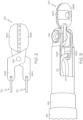
- FIGS. 1A-1B show an exemplary medical device 100 in accordance with an example of this disclosure.
- Medical device 100 may include a handle 102 having a longitudinal length defined by a proximal end 104 and a distal end 106.
- Proximal end 104 may include a grasping feature that is configured to facilitate manual control of handle 102.
- the grasping feature may include a ring that is sized and shaped to receive a finger of the user of medical device 100.
- Handle 102 may further include a pair of tracks 108, 109 positioned along opposing sides of handle 102 and extending between proximal end 104 and distal end 106.
- tracks 108, 109 may define a travel path of one or more actuators 110, 112, and a longitudinal length of tracks 108, 109 may define an articulation and actuation extent of medical device 100.
- Medical device 100 may further include a pair of actuators 110, 112 movably coupled to handle 102 at tracks 108, 109.
- medical device 100 may include a first actuator 110 slidably coupled to first track 108, and a second actuator 112 slidably coupled to second track 109.
- First actuator 110 may be configured to translate along first track 108
- second actuator 112 may be configured to translate along second track 109, in one or more directions A, B. That is, each of first actuator 110 and second actuator 112 may move in either a first direction A or a second direction B.
- First actuator 110 and second actuator 112 may be configured to move independently of, and relative to, one another.
- Actuators 110, 112 may be actuated in various suitable manners and sequences, such as simultaneously and/or separately from one another.
- first actuator 110 and second actuator 112 may be disposed about a circumference of handle 102 and collectively enclose at least a portion of handle 102 therebetween.
- first actuator 110 may include a body with a grasping feature 114 extending laterally outward from the body of first actuator 110.
- Second actuator 112 may include a body with a grasping feature 116 extending laterally outward from the body of second actuator 112.
- Each grasping feature 114, 116 may be configured to facilitate movement of the respective actuator 110, 112 relative to the corresponding track 108, 109.
- each grasping feature 114, 116 may include a ring that is sized and shaped to receive a corresponding finger of a user of medical device 100. It should be appreciated that grasping features 114, 116 may have various other suitable sizes, shapes, and/or configurations without departing from a scope of this disclosure.
- Medical device 100 may include a shaft 120 fixed to and extending distally from handle 102, and particularly from distal end 106.
- Shaft 120 may include a proximal shaft 122 and a distal articulation joint 130.
- a proximal end of proximal shaft 122 may extend be coupled to distal end 106, and a proximal end of distal articulation joint 130 may be coupled to a distal end of proximal shaft 122.
- Medical device 100 may further include an end effector 140 coupled to a distal end of distal articulation joint 130.
- End effector 140 may include one or more parts, such as a clevis 142, a first jaw 148A, and a second jaw 148B.
- Clevis 142 may be secured to the distal end of distal articulation joint 130, and jaws 148A, 148B may be pivotably coupled to clevis 142. As described further herein, each jaw 148A, 148B may be movable in response to translation of actuators 110, 112. In the embodiment, end effector 140 may exclude one or more links coupled to the pair of jaws 148A, 148B. As described further herein, medical device 100 may be configured to enhance a grasping force between jaws 148A, 148B from the exclusion of links in end effector 140.
- each jaw 148A, 148B may be coupled to at least one of the actuators 110, 112 via the corresponding wire 170, 172.
- first jaw 148A may be coupled to second actuator 112 via second wire 172
- second jaw 148B may be coupled to first actuator 110 via first wire 170.
- first jaw 148A may include a proximal arm 144A that receives second wire 172
- second jaw 148B may include a proximal arm 144B that receives first wire 170.
- end effector 140 excludes links (or any other structures) between jaws 148A, 148B and wires 170, 172, such that wires 170, 172 are coupled directly to jaws 148A, 148B at the corresponding proximal arm 144A, 144B.
- Medical device 100 may be operable to minimize a mechanical loss of force transfer between actuators 110, 112 and jaws 148A, 148B from the exclusion of one or more links (or any other structures) between wires 170, 172 and jaws 148A, 148B.
- End effector 140 is depicted in FIG. 2 with clevis 142 omitted for illustrative purposes only.
- End effector 140 may include a pin 146 defining a pivot point of jaws 148A, 148B, i.e., jaws 148A, 148B may be movably coupled to one another about pin 146. Further, first jaw 148A and second jaw 148B may be movably coupled to clevis 142 at pin 146.
- Each jaw 148A, 148B may include a plurality of teeth along an interior surface for grasping an object disposed between jaws 148A, 148B, such as, for example, tissue.
- end effector 140 may include various suitable configurations, including, but not limited to, one or more clamps, shears, forceps, scissors, suturing devices, lighting devices, imaging systems, grasper assemblies, and various other suitable tools and/or devices. Accordingly, end effector 140 shown and described herein is merely exemplary such that medical device 100 may include various other end effectors without departing from a scope of this disclosure.
- first wire 170 and second wire 172 may be disposed within shaft 120, and extend distally from distal articulation joint 130 to couple with proximal arms 144B, 144A, respectively.
- shaft 120 may include a first lumen 128A configured to receive first wire 170, and a second lumen 128B configured to receive second wire 172.
- first actuator 110 along handle 102 may provide movement of first wire 170 within first lumen 128A and a corresponding movement of second jaw 148B.
- movement of second actuator 112 along handle 102 may provide movement of second wire 172 within second lumen 128B and a corresponding movement of first jaw 148A.
- each of first actuator 110 and second actuator 112 may be configured to actuate end effector 140 and articulate distal articulation joint 130.
- shaft 120 e.g., proximal shaft 122, distal articulation joint 130
- first inner layer 134 that is in a braided configuration
- second inner layer 136 e.g., multi-lumen shaft
- proximal shaft 122 is depicted with a plurality of layers.
- proximal shaft 122 may include an outer layer 123, a first inner layer 124, a second inner layer 126, and a third inner layer 128.
- Outer layer 123 may be disposed about first inner layer 124, and may be configured to insulate first inner layer 124, such as, for example, from a tool (e.g., cautery knife) positioned adjacent to medical device 100.
- outer layer 123 may be formed of an insulating material, such as, for example, reflow including Pebax ® resin.
- Outer layer 123 may be further formed of a material having a predefined hardness ranging from about 10 D (durometer) to about 100 D, and more particularly 30 D to 75 D. In other embodiments, outer layer 123 may be omitted entirely.
- First inner layer 124 may be disposed about second inner layer 126, and may include a braid formed of a plurality of wires (e.g., flat, round, etc.) braided to one another.
- first inner layer 124 may include a plurality of wires ranging from about 10 wires to about 100 wires, and more particularly 16 to 32 wires.
- a braiding of first inner layer 124 may be angled, such as at an angle ranging from about 10 degrees to about 100 degrees, and more particularly 30 to 50 degrees.
- the braiding of first inner layer 124 may be in various suitable patterns, including, for example, a diamond braid, a Hercules braid, and more.
- First inner layer 124 may be configured to increase a torque and/or stiffness of proximal shaft 122. In other embodiments, first inner layer 124 may be omitted entirely.
- second inner layer 126 may be disposed about third inner layer 128, and may include a coil that is wound (e.g., clockwise, counter clockwise, etc.) about third inner layer 128.
- a coil pitch of second inner layer 126 may be substantially similar to a wire diameter of the coil.
- Second inner layer 126 may be configured to provide a rigidity to proximal shaft 122.
- Third inner layer 128 may be formed of polytetrafluoroethylene (PTFE) and include first lumen 128A and second lumen 128B for receiving each of first wire 170 and second wire 172, respectively.
- the lumens of third inner layer 128 may have similar and/or different diameters relative to one another.
- Third inner layer 128 may include a diameter ranging from about 0.5 millimeters to about 1.0 millimeters, and particularly 0.8 millimeters.
- First lumen 128A may include a diameter ranging from about 0.2 millimeters to about 0.8 millimeters, and particularly 0.4 millimeters
- second lumen 128B may include a diameter ranging from about 0.1 millimeters to about 0.7 millimeters, and particularly 0.3 millimeters.
- third inner layer 128 may be omitted entirely or in lieu of a pair of sheaths each defining a lumen for receiving at least one of wires 170, 172.
- first wire 170 and second wire 172 may be formed of various materials, including, for example, stainless steel, Nitinol, plastic, aluminum, etc. In some examples, first wire 170 and/or second wire 172 may be coated with PTFE and/or other suitable materials. Additionally, first wire 170 and/or second wire 172 may each include a single wire or may be a multi-strand wire assembly. As described in further detail herein, each of first wire 170 and second wire 172 may be configured to provide articulation of shaft 120 and actuation of end effector 140.
- distal articulation joint 130 is depicted with a plurality of layers.
- distal articulation joint 130 may include an outer layer 132, a first inner layer 134, and a second inner layer 136.
- Outer layer 132 may be disposed about first inner layer 134, and may be configured to insulate first inner layer 134.
- outer layer 132 may be formed of an insulating material, such as, for example, reflow including Pebax ® resin.
- Outer layer 132 may be formed of a material having a predefined hardness that is relatively less than outer layer 122 of proximal shaft 122.
- outer layer 132 may have a predefined hardness ranging from about 5 D to about 100 D, and more particularly 30 D to about 50 D.
- distal articulation joint 130 may be configured to bend relative to proximal shaft 122 in response to an actuation of at least one of wires 170, 172.
- First inner layer 134 may be disposed about second inner layer 136, and may include a braid formed of a plurality of wires (e.g., flat, round, etc.) braided to one another.
- First inner layer 134 may be substantially similar to first inner layer 124.
- first inner layer 134 may include a plurality of wires ranging from about 10 wires to about 100 wires, and more particularly 16 to 32 wires. In other examples, first inner layer 134 may include fewer wires than first inner layer 124.
- First inner layer 134 may be configured to increase a torque and/or stiffness of distal articulation joint 130.
- a braiding of first inner layer 134 may be angled, such as at an angle ranging from about 10 degrees to about 100 degrees, and more particularly 30 to 50 degrees.
- the braiding of first inner layer 134 may be in various suitable patterns, including, for example, a diamond braid, a Hercules braid, and more.
- second inner layer 136 may be formed of polytetrafluoroethylene (PTFE), and may include first lumen 128A and second lumen 128B for receiving each of first wire 170 and second wire 172, respectively.
- first lumen 128A and second lumen 128B of second inner layer 136 may have similar and/or different diameters relative to one another.
- second inner layer 136 may be omitted entirely or in lieu of a pair of sheaths each defining a lumen for receiving at least one of wires 170, 172.
- Second inner layer 136 may be formed of a material having a predefined hardness ranging from about 15 D to about 95 D, and more particularly 33 D to 50 D.
- First wire 170 may extend distally from second inner layer 136 and through clevis 162 for engagement with proximal arm 144B (see FIGS. 2-3 ). First wire 170 may be secured to proximal arm 144B by an adhesive, welding, crimping, ultraviolet (UV) curing, etc. Second wire 172 may extend distally from second inner layer 136 and through clevis 162 for engagement with proximal arm 144A (see FIGS. 2-3 ). Second wire 172 may be secured to proximal arm 144A by an adhesive, welding, crimping, ultraviolet (UV) curing, etc.
- a medical instrument e.g., an endoscope
- Medical device 100 may be received within the medical instrument and end effector 140 may extend outwardly from the distal end of the medical instrument.
- end effector 140 may be positioned within the subject and at the target treatment site while handle 102 is positioned external from the subject at a proximal end of the medical instrument. It should be appreciated that end effector 140 will be maintained in an actuated (closed) state during delivery through the medical instrument.
- first actuator 110 and second actuator 112 may each be positioned in a first position relative to handle 102 such that distal articulation joint 130 is maintained in an unarticulated state (e.g., a longitudinal axis of distal articulation joint 130 is aligned with a longitudinal axis of shaft 120), and end effector 140 is maintained in an actuated state.
- actuators 110, 112 may be positioned along an intermediate portion of tracks 108, 109 such that wires 170, 172 are maintained at a neutral position relative to shaft 120 and end effector 140.
- first wire 170 does not apply a tensile force onto second jaw 144B
- second wire 172 does not apply a tensile force onto first jaw 144A, thereby maintaining end effector 140 in the actuated state and distal articulation joint 130 in an unarticulated state (e.g., parallel to shaft 120 and/or handle 102).
- first actuator 110 may be translated along first track 108 in the first direction A (e.g., proximally) to pull first wire 170 proximally relative to shaft 120 and handle 102.
- first actuator 110 may be moved to a proximalmost position, and configured to articulate distal articulation joint 130 toward a side of handle 102 including first actuator 110, thereby moving end effector 140 radially outward and in the first direction A.
- a user of medical device 100 may move first actuator 110 relative to handle 102 by pulling first actuator 110 proximally toward proximal end 104.
- First actuator 110 may slide relative to handle 102 in response to applying a proximal force on grasping feature 114.
- first wire 170 (secured to a body of first actuator 110 along a portion within handle 102) may move with grasping feature 114 in the first direction A relative to handle 102. With first wire 170 secured to proximal arm 144B, first actuator 110 may be configured to move first wire 170 relative to handle 102 and shaft 120.
- First actuator 110 may pull first wire 170 proximally to apply a proximal (pulling) force onto proximal arm 148B, thereby causing distal articulation joint 130 to bend.
- end effector 140 may be deflected in the first direction A, i.e. the same direction of movement as first actuator 110 relative to handle 102, since a connection point between wire 170 and arm 148B is off-center and radially outward of a longitudinal axis of distal articulation joint 130, towards a same side of medical device 100 as first actuator 110.
- a user of medical device 100 may selectively adjust a degree of articulation of distal articulation joint 130, and the corresponding extent of deflection of end effector 140, in response to a degree of movement of first actuator 110 relative to handle 102. Further, handle 102 may be rotated, to rotate shaft 120 and move end effector 140 relative to the target treatment site to facilitate further movement of medical device 100 toward a target object within the target treatment site. In some embodiments, second actuator 112 may remain stationary during translation of first actuator 110 relative to handle 102.
- second actuator 112 may be translated along second track 109 in the second direction B, that is opposite of the first direction A, to push second wire 172 distally relative to shaft 120 and handle 102.
- second actuator 112 may be moved to a distalmost position, thereby causing end effector 140 to transition from an actuated state ( FIG. 1A ) to an unactuated state.
- a user of medical device 100 may move second actuator 112 relative to handle 120 by sliding second actuator 112 distally toward distal end 106 to the distalmost position.
- Second actuator 112 may slide relative to handle 120 in response to applying a distal force on grasping feature 116.
- second wire 172 (secured to a body of second actuator 112 along a portion within handle 102) may move with grasping feature 116 relative to handle 102.
- second actuator 112 With second wire 170 secured to proximal arm 144A, second actuator 112 may be configured to move second wire 172 relative to handle 102 and shaft 120.
- Second actuator 112 may push second wire 172 distally to apply a distal (pushing) force onto the proximal arm 144A, thereby causing first jaw 148A to move about pin 146 and away from second jaw 148B.
- end effector 140 may be transitioned to the unactuated state with jaws 148A, 148B disengaged from one another.
- a user of medical device 100 may selectively adjust a degree of disengagement between jaws 148A, 148B in response to an extent of translation of second actuator 112 relative to second track 109.
- a gap formed between jaws 148A, 148B may correspond to a longitudinal translation of second actuator 112 along handle 102.
- first actuator 110 may remain stationary during translation of second actuator 112 relative to handle 102.
- End effector 140 may be maneuvered about the target treatment site by manipulating a position, orientation, and/or configuration of handle 102 with the grasping feature at proximal end 104 to position end effector 140 adjacent to the target object.
- second actuator 112 may be translated proximally in the first direction A (e.g., to a neutral and/or proximalmost position) to move first jaw 148A toward second jaw 148B, and clamp the target object (e.g., tissue) therebetween.
- actuators 110, 112 may provide multifunctional capabilities depending on a sequence of actuation of each actuator 110, 112 relative to one another.
- second actuator 112 may be moved in the first direction A (e.g., to the proximalmost position) in lieu of first actuator 110, such that distal articulation joint 130 may bend toward second actuator 112 and in the first direction A.
- subsequent actuation of first actuator 110 in the second direction B e.g., to the distalmost position
- medical device 100 may provide an ergonomic interface for manipulating a target object (e.g., tissue) during a procedure with a single hand of a user. Further, medical device 100 may provide multiple degrees of articulation and/or directions of movement via actuators 110, 112.
- a target object e.g., tissue
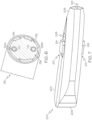
- FIG. 7 another exemplary medical device 200 is depicted according to an example of the disclosure. Except as otherwise described herein, medical device 200 may be configured and operable similar to medical device 100. Accordingly, like reference numerals are used to identify like components.
- Medical device 200 may include a handle 202 having a longitudinal length defined between a proximal end 204 and a distal end 206.
- Handle 102 may be sized, shaped, and configured to be graspable by a user of medical device 200. That is, handle 202 may provide an ergonomic interface for grasping medical device 200 and maneuvering handle 202 with a single hand.
- Handle 202 may further include a pair of tracks positioned along opposing sides of handle 202, and extending between proximal end 204 and distal end 206.
- handle 202 may include a first track 208 along a top wall of handle 202 and a second track (not shown) positioned along a bottom wall of handle 202.
- Each track may define a travel path of one or more actuators 210, 212, and a longitudinal length of the tracks may define an articulation and actuation extent of medical device 200.
- Medical device 200 may further include a pair of actuators 210, 212 movably coupled to handle 202 at the tracks.
- medical device 200 may include a first actuator 210 slidably coupled to first track 208, and a second actuator 212 slidably coupled to the second track.
- first track 208 and the second track may include openings formed along an exterior of handle 202, such that actuators 210, 212 may be at least partially disposed within the openings and seated inside handle 202.
- First actuator 210 may be configured to translate along first track 208
- second actuator 212 may be configured to translate along the second track in one or more directions (e.g., proximally, distally, etc.).
- first actuator 210 may be coupled to first wire 170 within handle 202
- second actuator 212 may be coupled to second wire 172 within handle 202. Accordingly, each actuator 210, 212 may be configured to move the corresponding wire 170, 172 relative to handle 202 in response to translating along the respective track.
- first actuator 210 may include a body with a grasping feature 214
- second actuator 212 may include a body with a grasping feature 216.
- Each grasping feature 214, 216 may be configured to facilitate movement of the respective actuator 210, 212 relative to the corresponding track.
- grasping features 214, 216 may include a slidable button and/or knob that is sized and shaped to receive a finger of a user thereon. It should be appreciated that grasping features 214, 216 may have various other suitable sizes, shapes, and/or configurations without departing from a scope of this disclosure.
- Medical device 200 may further include shaft 120 extending distally from handle 202, and particularly from distal end 206. Although not shown, it should be understood that medical device 200 may include proximal shaft 122 and distal articulation joint 130, with end effector 140 coupled to a distal end of articulation joint 130. Medical device 200 may be configured and operable similar to medical device 100 described above, such that movement of actuators 210, 212 relative to handle 202 may provide a similar articulation and actuation of shaft 120 and end effector 140, respectively, as described in detail above with respect to medical device 100.
- Each of the aforementioned systems, devices, assemblies, and methods may be used to manipulate target tissue with enhanced degree of maneuverability.
- a medical device with an intuitive handle capable of controlling an actuation and articulation of an end effector with a single hand
- a user may utilize another hand to control other devices and/or tools during a procedure for treating the target site.
- a user may reduce overall procedure time, increase efficiency of procedures, and/or avoid unnecessary harm to a subject's body caused by limited control of the other tools/devices.
Landscapes
- Health & Medical Sciences (AREA)
- Life Sciences & Earth Sciences (AREA)
- Surgery (AREA)
- Heart & Thoracic Surgery (AREA)
- Engineering & Computer Science (AREA)
- Biomedical Technology (AREA)
- Nuclear Medicine, Radiotherapy & Molecular Imaging (AREA)
- Medical Informatics (AREA)
- Molecular Biology (AREA)
- Animal Behavior & Ethology (AREA)
- General Health & Medical Sciences (AREA)
- Public Health (AREA)
- Veterinary Medicine (AREA)
- Ophthalmology & Optometry (AREA)
- Surgical Instruments (AREA)
Applications Claiming Priority (3)
| Application Number | Priority Date | Filing Date | Title |
|---|---|---|---|
| US202063081807P | 2020-09-22 | 2020-09-22 | |
| EP21786582.3A EP4216843B1 (de) | 2020-09-22 | 2021-09-21 | Medizinische gelenkvorrichtungen |
| PCT/IB2021/058602 WO2022064365A1 (en) | 2020-09-22 | 2021-09-21 | Medical articulation devices and methods of using the same |
Related Parent Applications (1)
| Application Number | Title | Priority Date | Filing Date |
|---|---|---|---|
| EP21786582.3A Division EP4216843B1 (de) | 2020-09-22 | 2021-09-21 | Medizinische gelenkvorrichtungen |
Publications (2)
| Publication Number | Publication Date |
|---|---|
| EP4559414A2 true EP4559414A2 (de) | 2025-05-28 |
| EP4559414A3 EP4559414A3 (de) | 2025-07-02 |
Family
ID=78078304
Family Applications (2)
| Application Number | Title | Priority Date | Filing Date |
|---|---|---|---|
| EP21786582.3A Active EP4216843B1 (de) | 2020-09-22 | 2021-09-21 | Medizinische gelenkvorrichtungen |
| EP25163484.6A Pending EP4559414A3 (de) | 2020-09-22 | 2021-09-21 | Medizinische gelenkvorrichtungen und verfahren zur verwendung davon |
Family Applications Before (1)
| Application Number | Title | Priority Date | Filing Date |
|---|---|---|---|
| EP21786582.3A Active EP4216843B1 (de) | 2020-09-22 | 2021-09-21 | Medizinische gelenkvorrichtungen |
Country Status (6)
| Country | Link |
|---|---|
| US (3) | US12042166B2 (de) |
| EP (2) | EP4216843B1 (de) |
| JP (2) | JP7686063B2 (de) |
| KR (1) | KR20230071162A (de) |
| CN (1) | CN116209403A (de) |
| WO (1) | WO2022064365A1 (de) |
Families Citing this family (3)
| Publication number | Priority date | Publication date | Assignee | Title |
|---|---|---|---|---|
| US12016585B2 (en) * | 2020-03-10 | 2024-06-25 | Boston Scientific Medical Device Limited | Medical device handle assemblies and methods of using the same |
| KR20260049303A (ko) * | 2023-08-16 | 2026-04-13 | 보스톤 싸이엔티픽 싸이메드 인코포레이티드 | 엔드 이펙터를 조향, 작동, 및/또는 제어하기 위한 의료 디바이스 및 관련 방법 |
| US20250090188A1 (en) * | 2023-09-15 | 2025-03-20 | Boston Scientific Medical Device Limited | Reusable handles for medical systems and devices, and related methods of use |
Family Cites Families (18)
| Publication number | Priority date | Publication date | Assignee | Title |
|---|---|---|---|---|
| US6569105B1 (en) | 2000-09-14 | 2003-05-27 | Syntheon, Llc | Rotatable and deflectable biopsy forceps |
| US7951165B2 (en) * | 2003-08-18 | 2011-05-31 | Boston Scientific Scimed, Inc. | Endoscopic medical instrument and related methods of use |
| US7052489B2 (en) * | 2003-12-05 | 2006-05-30 | Scimed Life Systems, Inc. | Medical device with deflecting shaft and related methods of manufacture and use |
| US20090171161A1 (en) | 2007-12-10 | 2009-07-02 | Usgi Medical, Inc. | Steerable endoscopic instruments |
| US9302073B2 (en) * | 2008-03-31 | 2016-04-05 | Karl Storz Gmbh & Co. Kg | Medical instrument with a lockable bend control mechanism |
| JP5161681B2 (ja) | 2008-07-22 | 2013-03-13 | 和也 赤星 | 内視鏡用処置具 |
| JPWO2010071064A1 (ja) * | 2008-12-16 | 2012-05-31 | オリンパスメディカルシステムズ株式会社 | 処置具 |
| US8333780B1 (en) * | 2009-06-05 | 2012-12-18 | Okay Industries, Inc. | Surgical tool and method of operation |
| JP5509392B2 (ja) | 2012-03-08 | 2014-06-04 | オリンパスメディカルシステムズ株式会社 | ガイドシース |
| WO2014053652A1 (en) * | 2012-10-06 | 2014-04-10 | Steerable Instruments Bvba | Crosstalk reducing handle for surgical articulated instruments |
| US9675782B2 (en) * | 2013-10-10 | 2017-06-13 | Medtronic Vascular, Inc. | Catheter pull wire actuation mechanism |
| US9987000B2 (en) * | 2014-12-18 | 2018-06-05 | Ethicon Llc | Surgical instrument assembly comprising a flexible articulation system |
| NL2015423B1 (en) * | 2015-09-10 | 2017-03-29 | Deam Holding B V | Surgical instrument. |
| JPWO2017110287A1 (ja) * | 2015-12-25 | 2018-10-11 | 株式会社カネカ | 内視鏡用鉗子および内視鏡用鉗子の製造方法 |
| WO2017161049A1 (en) * | 2016-03-15 | 2017-09-21 | The Regents Of The University Of California | Articulable endoscopic instruments |
| KR102347945B1 (ko) | 2017-05-04 | 2022-01-06 | 아주대학교 산학협력단 | 관절운동과 회전운동이 가능한 미세 수술기구 |
| WO2018207799A1 (ja) * | 2017-05-08 | 2018-11-15 | 国立大学法人九州大学 | マニピュレータ |
| JP7193271B2 (ja) * | 2018-08-23 | 2022-12-20 | 周 中村 | 脊椎経皮的内視鏡下手術用の屈曲鉗子 |
-
2021
- 2021-09-21 US US17/480,276 patent/US12042166B2/en active Active
- 2021-09-21 KR KR1020237013246A patent/KR20230071162A/ko active Pending
- 2021-09-21 CN CN202180064267.5A patent/CN116209403A/zh active Pending
- 2021-09-21 WO PCT/IB2021/058602 patent/WO2022064365A1/en not_active Ceased
- 2021-09-21 EP EP21786582.3A patent/EP4216843B1/de active Active
- 2021-09-21 EP EP25163484.6A patent/EP4559414A3/de active Pending
- 2021-09-21 JP JP2023518110A patent/JP7686063B2/ja active Active
-
2024
- 2024-06-20 US US18/748,198 patent/US12484922B2/en active Active
-
2025
- 2025-05-20 JP JP2025083699A patent/JP2025109900A/ja active Pending
- 2025-11-06 US US19/381,468 patent/US20260123949A1/en active Pending
Also Published As
| Publication number | Publication date |
|---|---|
| JP2023541691A (ja) | 2023-10-03 |
| EP4216843A1 (de) | 2023-08-02 |
| EP4216843B1 (de) | 2025-03-19 |
| JP2025109900A (ja) | 2025-07-25 |
| US20240335207A1 (en) | 2024-10-10 |
| US12042166B2 (en) | 2024-07-23 |
| EP4559414A3 (de) | 2025-07-02 |
| US12484922B2 (en) | 2025-12-02 |
| CN116209403A (zh) | 2023-06-02 |
| KR20230071162A (ko) | 2023-05-23 |
| US20260123949A1 (en) | 2026-05-07 |
| US20220087703A1 (en) | 2022-03-24 |
| WO2022064365A1 (en) | 2022-03-31 |
| JP7686063B2 (ja) | 2025-05-30 |
Similar Documents
| Publication | Publication Date | Title |
|---|---|---|
| US12484922B2 (en) | Medical articulation devices and methods of using the same | |
| CN111936072A (zh) | 具有柔线布设的可关节运动的医疗装置 | |
| US20250268460A1 (en) | Medical articulation devices and methods of using the same | |
| CN114760904A (zh) | 具有多个自由度的医疗装置及相关方法 | |
| EP4216844B1 (de) | Medizinische gelenkvorrichtungen | |
| US20250248699A1 (en) | Articulation mechanisms and methods of use | |
| US12390205B2 (en) | Medical device handle assemblies and methods of using the same | |
| US12576242B2 (en) | Medical systems, devices, and related methods | |
| US20220095888A1 (en) | Medical systems, devices, and related methods | |
| JP2024526564A (ja) | 医療システム、デバイス、および関連する方法 | |
| AU2022301818A1 (en) | Medical device handles with multiple degrees of freedom | |
| KR20240028447A (ko) | 내시경 액세서리 제어장치들 및 사용 방법들 |
Legal Events
| Date | Code | Title | Description |
|---|---|---|---|
| PUAI | Public reference made under article 153(3) epc to a published international application that has entered the european phase |
Free format text: ORIGINAL CODE: 0009012 |
|
| STAA | Information on the status of an ep patent application or granted ep patent |
Free format text: STATUS: REQUEST FOR EXAMINATION WAS MADE |
|
| 17P | Request for examination filed |
Effective date: 20250411 |
|
| AC | Divisional application: reference to earlier application |
Ref document number: 4216843 Country of ref document: EP Kind code of ref document: P |
|
| AK | Designated contracting states |
Kind code of ref document: A2 Designated state(s): AL AT BE BG CH CY CZ DE DK EE ES FI FR GB GR HR HU IE IS IT LI LT LU LV MC MK MT NL NO PL PT RO RS SE SI SK SM TR |
|
| PUAL | Search report despatched |
Free format text: ORIGINAL CODE: 0009013 |
|
| AK | Designated contracting states |
Kind code of ref document: A3 Designated state(s): AL AT BE BG CH CY CZ DE DK EE ES FI FR GB GR HR HU IE IS IT LI LT LU LV MC MK MT NL NO PL PT RO RS SE SI SK SM TR |
|
| RIC1 | Information provided on ipc code assigned before grant |
Ipc: A61B 17/29 20060101AFI20250527BHEP |
|
| RIN1 | Information on inventor provided before grant (corrected) |
Inventor name: SG, SHARATH KUMAR Inventor name: SCUTTI, JAMES J. Inventor name: SHARMA, DEEPAK KUMAR |
|
| STAA | Information on the status of an ep patent application or granted ep patent |
Free format text: STATUS: EXAMINATION IS IN PROGRESS |
|
| 17Q | First examination report despatched |
Effective date: 20260408 |