EP4557641A2 - Übertragungsvorrichtung und übertragungsverfahren für ressourcenzuweisungsinformationen - Google Patents
Übertragungsvorrichtung und übertragungsverfahren für ressourcenzuweisungsinformationen Download PDFInfo
- Publication number
- EP4557641A2 EP4557641A2 EP25168314.0A EP25168314A EP4557641A2 EP 4557641 A2 EP4557641 A2 EP 4557641A2 EP 25168314 A EP25168314 A EP 25168314A EP 4557641 A2 EP4557641 A2 EP 4557641A2
- Authority
- EP
- European Patent Office
- Prior art keywords
- user
- assignment
- rus
- subfield
- type
- Prior art date
- Legal status (The legal status is an assumption and is not a legal conclusion. Google has not performed a legal analysis and makes no representation as to the accuracy of the status listed.)
- Pending
Links
Images


Classifications
-
- H—ELECTRICITY
- H04—ELECTRIC COMMUNICATION TECHNIQUE
- H04W—WIRELESS COMMUNICATION NETWORKS
- H04W72/00—Local resource management
- H04W72/20—Control channels or signalling for resource management
- H04W72/23—Control channels or signalling for resource management in the downlink direction of a wireless link, i.e. towards a terminal
-
- H—ELECTRICITY
- H04—ELECTRIC COMMUNICATION TECHNIQUE
- H04J—MULTIPLEX COMMUNICATION
- H04J11/00—Orthogonal multiplex systems, e.g. using WALSH codes
- H04J11/0069—Cell search, i.e. determining cell identity [cell-ID]
-
- H—ELECTRICITY
- H04—ELECTRIC COMMUNICATION TECHNIQUE
- H04L—TRANSMISSION OF DIGITAL INFORMATION, e.g. TELEGRAPHIC COMMUNICATION
- H04L1/00—Arrangements for detecting or preventing errors in the information received
- H04L1/004—Arrangements for detecting or preventing errors in the information received by using forward error control
- H04L1/0045—Arrangements at the receiver end
- H04L1/0046—Code rate detection or code type detection
-
- H—ELECTRICITY
- H04—ELECTRIC COMMUNICATION TECHNIQUE
- H04L—TRANSMISSION OF DIGITAL INFORMATION, e.g. TELEGRAPHIC COMMUNICATION
- H04L5/00—Arrangements affording multiple use of the transmission path
- H04L5/0001—Arrangements for dividing the transmission path
- H04L5/0003—Two-dimensional division
- H04L5/0005—Time-frequency
- H04L5/0007—Time-frequency the frequencies being orthogonal, e.g. OFDM(A) or DMT
- H04L5/001—Time-frequency the frequencies being orthogonal, e.g. OFDM(A) or DMT the frequencies being arranged in component carriers
-
- H—ELECTRICITY
- H04—ELECTRIC COMMUNICATION TECHNIQUE
- H04L—TRANSMISSION OF DIGITAL INFORMATION, e.g. TELEGRAPHIC COMMUNICATION
- H04L5/00—Arrangements affording multiple use of the transmission path
- H04L5/003—Arrangements for allocating sub-channels of the transmission path
- H04L5/0032—Distributed allocation, i.e. involving a plurality of allocating devices, each making partial allocation
- H04L5/0035—Resource allocation in a cooperative multipoint environment
-
- H—ELECTRICITY
- H04—ELECTRIC COMMUNICATION TECHNIQUE
- H04L—TRANSMISSION OF DIGITAL INFORMATION, e.g. TELEGRAPHIC COMMUNICATION
- H04L5/00—Arrangements affording multiple use of the transmission path
- H04L5/003—Arrangements for allocating sub-channels of the transmission path
- H04L5/0044—Allocation of payload; Allocation of data channels, e.g. PDSCH or PUSCH
-
- H—ELECTRICITY
- H04—ELECTRIC COMMUNICATION TECHNIQUE
- H04L—TRANSMISSION OF DIGITAL INFORMATION, e.g. TELEGRAPHIC COMMUNICATION
- H04L5/00—Arrangements affording multiple use of the transmission path
- H04L5/003—Arrangements for allocating sub-channels of the transmission path
- H04L5/0048—Allocation of pilot signals, i.e. of signals known to the receiver
- H04L5/005—Allocation of pilot signals, i.e. of signals known to the receiver of common pilots, i.e. pilots destined for multiple users or terminals
-
- H—ELECTRICITY
- H04—ELECTRIC COMMUNICATION TECHNIQUE
- H04L—TRANSMISSION OF DIGITAL INFORMATION, e.g. TELEGRAPHIC COMMUNICATION
- H04L5/00—Arrangements affording multiple use of the transmission path
- H04L5/003—Arrangements for allocating sub-channels of the transmission path
- H04L5/0048—Allocation of pilot signals, i.e. of signals known to the receiver
- H04L5/0051—Allocation of pilot signals, i.e. of signals known to the receiver of dedicated pilots, i.e. pilots destined for a single user or terminal
-
- H—ELECTRICITY
- H04—ELECTRIC COMMUNICATION TECHNIQUE
- H04L—TRANSMISSION OF DIGITAL INFORMATION, e.g. TELEGRAPHIC COMMUNICATION
- H04L5/00—Arrangements affording multiple use of the transmission path
- H04L5/003—Arrangements for allocating sub-channels of the transmission path
- H04L5/0053—Allocation of signalling, i.e. of overhead other than pilot signals
-
- H—ELECTRICITY
- H04—ELECTRIC COMMUNICATION TECHNIQUE
- H04L—TRANSMISSION OF DIGITAL INFORMATION, e.g. TELEGRAPHIC COMMUNICATION
- H04L5/00—Arrangements affording multiple use of the transmission path
- H04L5/003—Arrangements for allocating sub-channels of the transmission path
- H04L5/0058—Allocation criteria
- H04L5/006—Quality of the received signal, e.g. BER, SNR, water filling
-
- H—ELECTRICITY
- H04—ELECTRIC COMMUNICATION TECHNIQUE
- H04L—TRANSMISSION OF DIGITAL INFORMATION, e.g. TELEGRAPHIC COMMUNICATION
- H04L5/00—Arrangements affording multiple use of the transmission path
- H04L5/0091—Signalling for the administration of the divided path, e.g. signalling of configuration information
- H04L5/0094—Indication of how sub-channels of the path are allocated
-
- H—ELECTRICITY
- H04—ELECTRIC COMMUNICATION TECHNIQUE
- H04W—WIRELESS COMMUNICATION NETWORKS
- H04W40/00—Communication routing or communication path finding
- H04W40/24—Connectivity information management, e.g. connectivity discovery or connectivity update
-
- H—ELECTRICITY
- H04—ELECTRIC COMMUNICATION TECHNIQUE
- H04W—WIRELESS COMMUNICATION NETWORKS
- H04W74/00—Wireless channel access
- H04W74/002—Transmission of channel access control information
- H04W74/004—Transmission of channel access control information in the uplink, i.e. towards network
-
- H—ELECTRICITY
- H04—ELECTRIC COMMUNICATION TECHNIQUE
- H04B—TRANSMISSION
- H04B7/00—Radio transmission systems, i.e. using radiation field
- H04B7/02—Diversity systems; Multi-antenna system, i.e. transmission or reception using multiple antennas
- H04B7/04—Diversity systems; Multi-antenna system, i.e. transmission or reception using multiple antennas using two or more spaced independent antennas
- H04B7/0413—MIMO systems
- H04B7/0452—Multi-user MIMO systems
-
- H—ELECTRICITY
- H04—ELECTRIC COMMUNICATION TECHNIQUE
- H04L—TRANSMISSION OF DIGITAL INFORMATION, e.g. TELEGRAPHIC COMMUNICATION
- H04L27/00—Modulated-carrier systems
- H04L27/26—Systems using multi-frequency codes
- H04L27/2601—Multicarrier modulation systems
- H04L27/2602—Signal structure
- H04L27/261—Details of reference signals
-
- H—ELECTRICITY
- H04—ELECTRIC COMMUNICATION TECHNIQUE
- H04L—TRANSMISSION OF DIGITAL INFORMATION, e.g. TELEGRAPHIC COMMUNICATION
- H04L5/00—Arrangements affording multiple use of the transmission path
- H04L5/0001—Arrangements for dividing the transmission path
- H04L5/0003—Two-dimensional division
- H04L5/0005—Time-frequency
- H04L5/0007—Time-frequency the frequencies being orthogonal, e.g. OFDM(A) or DMT
-
- H—ELECTRICITY
- H04—ELECTRIC COMMUNICATION TECHNIQUE
- H04W—WIRELESS COMMUNICATION NETWORKS
- H04W84/00—Network topologies
- H04W84/02—Hierarchically pre-organised networks, e.g. paging networks, cellular networks, WLAN [Wireless Local Area Network] or WLL [Wireless Local Loop]
- H04W84/10—Small scale networks; Flat hierarchical networks
- H04W84/12—WLAN [Wireless Local Area Networks]
-
- Y—GENERAL TAGGING OF NEW TECHNOLOGICAL DEVELOPMENTS; GENERAL TAGGING OF CROSS-SECTIONAL TECHNOLOGIES SPANNING OVER SEVERAL SECTIONS OF THE IPC; TECHNICAL SUBJECTS COVERED BY FORMER USPC CROSS-REFERENCE ART COLLECTIONS [XRACs] AND DIGESTS
- Y02—TECHNOLOGIES OR APPLICATIONS FOR MITIGATION OR ADAPTATION AGAINST CLIMATE CHANGE
- Y02D—CLIMATE CHANGE MITIGATION TECHNOLOGIES IN INFORMATION AND COMMUNICATION TECHNOLOGIES [ICT], I.E. INFORMATION AND COMMUNICATION TECHNOLOGIES AIMING AT THE REDUCTION OF THEIR OWN ENERGY USE
- Y02D30/00—Reducing energy consumption in communication networks
- Y02D30/70—Reducing energy consumption in communication networks in wireless communication networks
Definitions
- the present disclosure generally pertains to wireless communications and, more particularly, to a method for formatting and transmitting resource assignment information in a wireless communications system.
- 802.11ax High Efficiency
- WLAN Wireless Local Area Network
- OFDMA Orthogonal Frequency Division Multiple Access
- OFDM Orthogonal Frequency Division Multiplexing
- OFDM Orthogonal Frequency Division Multiplexing
- an input data stream is divided into several parallel substreams with a lower data rate (accordingly, increased symbol duration), and the substreams are modulated with respective orthogonal subcarriers and are transmitted.
- the increased symbol duration improves the robustness of OFDM system with respect to the channel delay spread.
- introduction of a CP Cyclic Prefix
- OFDM modulation may be realized by an efficient IFFT (Inverse Fast Fourier Transform) that makes a plurality of subcarriers usable with little complexity.
- IFFT Inverse Fast Fourier Transform
- time and frequency resources are defined by OFDM symbols in a time domain and subcarriers in a frequency domain.
- OFDMA is a multiple access scheme that performs multiple operations of data streams to and from the plurality of users over the time and frequency resources of the OFDM system.
- a radio communication access point apparatus (hereinafter simply “access point”) adaptively assigns subcarriers to a plurality of radio communication station apparatuses (i.e., terminal ap-parartus, herein-after simply “stations”) based on reception qualities of frequency bands of the stations (also called as "STAs"). This makes it possible to obtain a maximum multiuser diversity effect and perform communication quite efficiently.
- Frequency scheduling is generally performed based on a Resource Unit (RU).
- a RU comprises a plurality of consecutive subcarriers.
- the RUs are assigned by an access point (AP) to each of a plurality of STAs with which the AP communicates.
- the resource assignment result of frequency scheduling performed by the AP shall be reported to the STAs as resource assignment information.
- 802.11ax is packet oriented and does not support control channels for transmitting resource assignment information.
- NPL 1 IEEE802.11-15/0132r5, Specification Framework for TGax, May 2015 NPL 2: IEEE802.11-15/0330r5, OFDMA Numerology and Structure, May 2015 NPL 3: IEEE802.11-15/0586r1, Frequency Diversity Options in OFDMA, May 2015 NPL 4: IEEE802.11-15/0621r2, Design Principles for HE Preamble, May 2015 NPL 5: IEEE802.11-15/0574r0, SIG Structure for UL PPDU, May 2015 NPL 6: IEEE Std 802.11ac-2013
- a challenge is how to achieve flexible frequency scheduling while reducing an increase of the overhead for reporting resource assignment information.
- the techniques disclosed here feature: a transmission apparatus of the present disclosure comprising an assignment information generator which, in operation, assigns resources on a resource unit (RU) basis to one or more terminal stations (STAs) and generates assignment information that specifies RUs allocated to the one or more STAs; a transmission signal generator which, in operation, generates a transmission signal that includes a legacy preamble, a non-legacy preamble and a data field, wherein the non-legacy preamble comprises a first signal field and a second signal field that carry a set ID and the assignment information, and wherein the set ID identifies one assignment set comprising the one or more STAs and a plurality of assignment indices, and wherein the assignment information comprises a resource assignment indication for each of a plurality of assignments which are referenced by the plurality of assignment indices; and a transmitter which, in operation, transmits the generated transmission signal.
- an assignment information generator which, in operation, assigns resources on a resource unit (RU) basis to one or more terminal stations
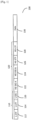
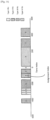
- Figure 1 illustrates an example format of PPDU (Physical layer Protocol Data Unit) 100 according to the prior art [see NPL 1 and 4].
- the PPDU 100 comprises a legacy preamble 110, a non-legacy preamble (i.e., High Efficiency (HE) preamble) 120 and a data field 130.
- HE High Efficiency
- the data field 130 carries the payload for one or more STAs.
- the payload is carried on a designated resource in units of Resource Unit (RU) spanning a plurality of OFDM symbols.
- RU Resource Unit
- a RU may have different types depending on the number of constituent subcarriers per RU.
- OFDM symbols in the data field 130 shall use a DFT period of 12.8 ⁇ s and subcarrier spacing of 78.125 kHz.
- CBW channel bandwidth
- the 20MHz OFDMA supports four types of RUs.
- the Type I RU comprises 26 consecutive tones and has a bandwidth of about 2MHz.
- the Type II RU comprises 52 consecutive tones and has a bandwidth of about 4.1MHz.
- the Type III RU comprises 106 consecutive tones and has a bandwidth of about 8.3MHz.
- the Type IV RU comprises 242 consecutive tones and has a bandwidth of about 18.9MHz.
- the maximum number of Type I RUs, Type II RUs, Type III RUs and Type IV RUs which the 20MHz OFDMA is able to support is nine, four, two and one, respectively.
- a mix of different types of RUs can be accomodated in the 20MHz OFDMA.
- the 20MHz OFDMA may be divided into one Type III RU 202, three Type I RUs 204, 208 and 210 as well as one Type II RU 206.
- the 40MHz OFDMA also supports Type V RU, which comprises 484 consecutive tones and has a bandwidth of about 37.8MHz.
- the maximum number of Type I RUs, Type II RUs, Type III RUs, Type IV RUs and Type V RUs which the 40MHz OFDMA is able to support is eighteen, eight, four, two and one, respectively. Similar to the 20MHz OFDMA, a mix of different types of RUs can also be accomodated in the 40MHz OFDMA.
- the 80MHz OFDMA also supports Type VI RU, which comprises 996 consecutive tones and has a bandwidth of about 77.8MHz.
- the maximum number of Type I RUs, Type II RUs, Type III RUs, Type IV RUs, Type V RUs and Type VI RUs which the 80MHz OFDMA is able to support is thirty-seven, sixteen, eight, four, two and one, respectively. Similar to the 20MHz or 40MHz OFDMA, a mix of different types of RUs can also be accomodated in the 80MHz OFDMA.
- the 80+80MHz OFDMA or 160MHz OFDMA also supports six types of RU, i.e., Type I RU, Type II RU, Type III RU, Type IV RU, Type V RU and Type VI RU.
- the maximum number of Type I RUs, Type II RUs, Type III RUs, Type IV RUs, Type V RUs and Type VI RUs which the 80+80MHz OFDMA or 160MHz OFDMA is able to support is seventy-four, thirty-two, sixteen, eight, four and two, respectively. Similar to the 20MHz, 40MHz or 80MHz OFDMA, a mix of different types of RUs can also be accomodated in the 80+80MHz OFDMA or 160MHz OFDMA.
- Type IV RU in context of 20MHz OFDMA implies a non-OFDMA configuration, which refers to a case where OFDMA is not used in the data field 130 of Figure 1 . That is, the entire bandwidth of operation is scheduled for single user transmission or multiuser MIMO transmission.
- use of a Type V RU in context of 40MHz OFDMA or a Type VI RU in context of 80MHz OFDMA implies a non-OFDMA configuration.
- use of two Type VI RUs in context of 160MHz or 80+80MHz OFDMA implies a non-OFDMA configuration.
- Figure 5 illustrates an example of continuous resource allocation in the data field 130 according to the prior art [see NPL 2]. As shown in Figure 5 , a single RU is allocated to a specific STA in terms of single user transmission or a specific group of STAs in terms of multiuser MIMO transmission in one assignment.
- Figure 6 illustrates an example of non-continuous resource allocation in the data field 130 according to the prior art [see NPL 3].
- non-continuous resource allocation more than one RUs which may be not continuous in the frequency domain can be allocated in one assignment for the purpose of achieveing frequency diversity effect.
- three non-consecutive RUs 602, 604 and 606 are allocated in one assignment.
- the legacy preamble 110 comprises a L-STF (Legacy Short Training Field) 112, a L-LTF (Legacy Long Training Field) 114 and a L-SIG (Legacy SIGnal field) 116 in order to keep backward compatibility with legacy standard 802.11a/g/n/ac.
- the L-STF 112 is used for start-of-packet detection, AGC (Automatic Gain Control) setting, initial frequency offset estimation and initial time synchronization.
- the L-LTF 114 is used for further fine frequency offset estimation and time synchronization.
- the L-LTF 114 is also used to generate channel estimates for receiving and equalizing the L-SIG 116, HE-SIG-A (High Efficiency SIGnal A field) 122 and HE-SIG-B (High Efficiency SIGnal B field) 124.
- the HE preamble 120 comprises a first signal field (i.e., HE-SIG-A) 122, a second signal field (i.e., HE-SIG-B) 124, a HE-STF 126 and a HE-LTF 128.
- the HE-STF 126 is used to retrain AGC.
- the HE-LTF 128 comprises a plurality of HE-LTF symbols and is used to generate MIMO (Multiple Input Multiple Output) channel estimates for receiving and equalizing the data field 130.
- MIMO Multiple Input Multiple Output
- both the HE-SIG-A 122 and the HE-SIG-B 124 contain resource assignment information and user specific information which are used for each scheduled STA to decode its payload in the data field 130 at designated resource [see NPL 4].
- the HE-SIG-A 122 and HE-SIG-B 124 may contain neither resource assignment information nor user specific information since such information is preset by an AP and sent to scheduled STAs via a trigger frame which is carried in the data field of a previously transmitted DL PPDU [see NPL 5].
- both HE-SIG-A 122 and HE-SIG-B 124 shall use a DFT period of 3.2 ⁇ s and subcarrier spacing of 312.5 kHz in 802.11ax.
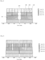
- Figure 7 illustrates an example of resource assignment according to a first embodiment of the present disclosure.
- the first embodiment is applicable to continous resource allocation where one or more RUs that are consecutive in the frequency domain are allocated in one assignment.
- Each assignment which is referenced by an assignment index, is addressed to either a specific STA in terms of single user transmission or a specific group of STAs in terms of multiuser MIMO transmission.
- the first assignment has a predetermined start position (e.g., the start tone index of a first RU (e.g., 202 as shown in Figure 2 ) which is known according to the size of CBW and the type of the first RU). And a start tone index of a subsequent assignment is next to the end tone index of its preceding assignment (i.e., there is no gap between consecutive assignments).
- the total number of assignments may be negotiated in advance between an Access Point (AP) and one or more station apparatus (STAs) or signaled to each STA in the HE-SIG-A field of DL PPDU or the trigger frame explicitly.
- AP Access Point
- STAs station apparatus
- a STA can determine that an assignment is the last assignment if a last RU (e.g., 210 as shown in Figure 2 ) is allocated in this assignment. Consequently, signaling of the total number of assignments can be omitted
- the start position of the first assignment is predetermined and the start position of a subsequent assignment can be determined from the end position of its preceding assignment. Therefore, it is enough to report the allocation bandwidth for each assignment. As a result, the overhead due to reporting resource assignment information for each assignment can be minimized.
- the resource assignment information includes a plurality of resource assignment indications, each of which corresponds to a particular assignment.
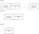
- Figure 8A illustrates a first example of resource assignment indication for one assignment according to the first embodiment of the present disclosure.
- the resource assignment indication for one assignment contains the number of allocated RUs and the type of each of allocated RUs, from which the allocation bandwidth for the assignment can be derived.
- Figure 8B illustrates a second example of resource assignment indication for one assignment according to the first embodiment of the present disclosure.
- the resource assignment indication for the assignment contains the number of allocated RUs and the type of allocated RUs, from which the allocation bandwidth for the assignment can be derived.
- Figure 8C illustrates a third example of resource assignment indication for one assignment according to the first embodiment of the present disclosure.
- the resource assignment indication for the assignment contains the type of allocated RU only, from which the allocation bandwidth for the assignment can be derived.
- the number of allocated RUs and the RU type are indicated separately by using bit signalings.
- a two-bit signaling shown in Table 1 can be used to indicate the number of allocated RUs. Accroding to Table 1, one RU to four RUs can be allocated in one assignment. [Table 1] Signaling bits Number of allocated RUs 00 1 01 2 10 3 11 4
- Table 2 a three-bit signaling shown in Table 2 can be used to indicate the RU type as follows: [Table 2] Signaling bits RU Type 000 Type I RU 001 Type II RU 010 Type III RU 011 Type IV RU 100 Type V RU 101 Type VI RU 110, 111 Reserved
- the type of the RU (Type II RU) allocated in the first assignment as shown in Figure 7 can be indicated by "001".
- the number of allocated RUs in case of 20MHz non-OFDMA transmission, shall be set to one and the type of allocated RUs shall be set to Type IV. In case of 40MHz non-OFDMA transmission, the number of allocated RUs shall be set to one and the type of allocated RUs shall be set to Type V. In case of 80MHz non-OFDMA transmission, the number of allocated RUs shall be set to one and the type of allocated RUs shall be set to Type VI. In case of 80+80MHz or 160MHz non-OFDMA transmission, the number of allocated RUs shall be set to two and the type of each of allocated RUs shall be set to Type VI. In this way, STA shall be able to determine whether an incoming DL PPDU 100 is an OFDMA PPDU or a non-OFDMA PPDU according to the resource assignment information without any dedicated signaling for such purpose.
- Figure 9 illustrates an example of resource assignment according to a second embodiment of the present disclosure.
- the second embodiment is also applicable to continous resource allocation where one or more RUs that are consecutive in the frequency domain can be allocated in one assignment.
- a start position of the first assignment may be variable and a gap may exist between consective assignments.
- the start tone index of an assignment is always larger than the end tone index of its preceding assignment.
- the total number of assignments may be negotiated in advance between an AP and one or more STAs or signaled to each STA in the HE-SIG-A field of DL PPDU or the trigger frame explicitly.
- the start position of the first assignment is variable and the start position of a subsequent assignment cannot be derived only from the end position of its preceding assignment. Therefore, in addition to allocation bandwidth, it is necessary to report start position for each assignment.
- the resource assignment information includes a plurality of resource assignment indications, each of which corresponds to a particular assignment.
- FIG 10A illustrates a first example of resource assignment indication for one assignment according to the second embodiment of the present disclosure.
- the resource assignment indication for one assignment contains the assignment offset, the number of allocated RUs and the type of each of allocated RUs.
- the assignment offset 902 is relative to the start tone index of the first Type I RU.
- the assignment offset (e.g., 904) is relative to the end tone index of its preceding assignment.
- the start position for a subsequent assignment can be determined according to the assignment offset and the end tone index of its preceding assignment.
- the allocation bandwidth for the assignment can be determined according to the number of allocated RUs and the type of each of allocated RUs.
- Figure 10B illustrates a second example of resource assignment indication for one assignment according to the second embodiment of the present disclosure.
- the resource assignment indication for the assignment contains the assignment offset, the number of allocated RUs and the type of allocated RUs.
- the start position for the assignment can be determined according to the assignment offset and the end tone index of its preceding assignment.
- the allocation bandwidth for the assignment can be determined according to the number of allocated RUs and the type of allocated RUs.
- Figure 10C illustrates a third example of resource assignment indication for one assignment according to the second embodiment of the present disclosure.
- the resource assignment indication for the assignment contains the assignment offset and the type of allocated RU.
- the start position for the assignment can be determined according to the assignment offset and the end tone index of its preceding assignment. Further, the allocation bandwidth for the assignment can be determined according to the type of allocated RU.
- reception quality of a RU is very poor for all scheduled STAs, the AP may not allocate the RU to them.
- This RU with poor reception quality is not used for resource assignment and becomes a gap between two assignments in this embodiment.
- the number of unused RUs that form a gap can be one or plural.
- the second embodiment provides more flexibility in frequency scheduling than the first embodiment.
- the overhead of reporting resource assignment information will slightly increase compared to the first embodiment. However, such overhead increase is not so siginificant.
- the assignment offset, the number of allocated RUs and the RU type are indicated separately by using bit signalings.
- a two-bit signaling shown in Table 3 can be used to indicate the assignment offset in units of the smallest RU (i.e., Type I RU).
- the assignment offset 902 (e.g., an offset of two Type I RUs) can be indicated by "10".
- Two-bit signaling shown in Table 1 can be used to indicate the number of allocated RUs.
- An alternative two-bit signaling is shown in Table 4. According to Table 4, zero RU to three RUs can be allocated in an assignment. When no RU is allocated in an assignment, the assignment is called a "dummy assignment" with zero RU allocation. [Table 4] Signaling bits Number of allocated RUs 00 0 01 1 10 2 11 3
- Two-bit signaling shown in Table 4 makes it possible to indicate an offset that is larger than three Type I RUs. For example, if there is an offset of five Type I RUs between a first assignment and a second assignment, this offset can be indicated by inserting a "dummy assignment" with zero RU allocation. More specifically, the "dummy assignment" located between the first assignment and the second assignment has an offset of three RUs and the second assignment has an offset of two RUs. Then, total offset will be five Type I RUs in this case.
- two-bit signaling shown in Table 4 can also make it possible to omit an explicit signaling of the total number of assignments.
- a "dummy assignment" with zero RU allocation, which has some offset can be used to indicate such unused resource (RU).
- the STA is able to determine that the dummy assignment is the last assignment.
- the number of allocated RUs in case of 20MHz non-OFDMA transmission, shall be set to one and the type of allocated RU shall be set to Type IV. In case of 40MHz non-OFDMA transmission, the number of allocated RUs shall be set to one and the type of allocated RU shall be set to Type V. In case of 80MHz non-OFDMA transmission, the number of allocated RUs shall be set to one and the type of allocated RU shall be set to Type VI. In case of 80+80MHz or 160MHz non-OFDMA transmission, the number of allocated RUs shall be set to two and the type of each of allocated RUs shall be set to Type VI. In this way, STA shall be able to determine whether incoming DL PPDU 100 is an OFDMA PPDU or a non-OFDMA PPDU according to the resource assignment information without any dedicated signaling for such purpose.
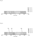
- Figure 11 illustrates an example of resource assignment according to a third embodiment of the present disclosure.
- the third embodiment is applicable to both continuous resource allocation and non-continuous resource allocation where one or more RUs which may not be consecutive in the frequency domain can be allocated in an assignment.
- the third embodiment enables even more flexibility in frequency scheduling than the first embodiment and the second embodiment.
- the total number of assignments may be negotiated in advance between an AP and one or more STAs, or signaled to each STA in the HE-SIG-A field of DL PPDU or the trigger frame explicitly.
- the resource assignment information includes a plurality of resource assignment indications, each of which corresponds to a particular assignment.
- Figure 12A illustrates a first example of resource assignment indication for one assignment according to the third embodiment of the present disclosure.
- the resource assignment indication contains the number of allocated RUs and the type and position information of each of allocated RUs,
- Figure 12B illustrates a second example of resource assignment indication for one assignment according to the third embodiment of the present disclosure.
- the resource assignment indication contains the type and position information of allocated RU.
- the type and position of an allocated RU are jointly signalled in a single signaling field. That is, a single signaling field can be used to indicate both position and type of each of allocated RUs.
- Figure 13 illustrates a signaling of the RU type and position information according to the third embodiment of the present disclosure. Encoding of the RU type and position information is performed for RUs which 20MHz OFDMA can support, followed by encoding for additional RUs which 40MHz OFDMA can support, encoding for additional RUs which 80MHz OFDMA can support, and encoding for additional RUs which 160MHz and 80+80MHz OFDMA can support in this order.
- assignment information regarding RUs of 20MHz OFDMA is allocated first, followed by assignment information regarding additional RUs of 40MHz OFDMA, assignment information regarding additional RUs of 80MHz OFDMA, and assignment information regarding additional RUs of 160MHz OFDMA in this order.
- CBW channel bandwidth
- an eight-bit signaling is used to indicate the type and position of an alllocated RU. So, the overhead of reporting resource assignment information further increases compared to the second embodiment.
- signaling whose length is variable depending on CBW may be used.
- an increase of the overhead of reporting resource assignment information due to much more flexible frequency scheduling is reduced.
- the type and position information of the RU allocated to the first assignment of 80MHz OFDMA as illustrated in Figure 11 can be indicated by "0001010".
- a STA supporting CBW up to 20MHz only needs to maintain a four-bit look up table.
- a STA supporting CBW up to 40MHz only needs to maintain a six-bit look up table and a STA supporting CBW up to 80MHz only needs to maintain a seven-bit look up table.
- the memory required for decoding the type and position information of each of allocated RUs is minimized for STAs with different PHY capabilities in terms of supported CBW.
- the number of allocated RUs in case of 20MHz non-OFDMA transmission, shall be set to one and the type and position of allocated RU shall be set to the first Type IV RU. In case of 40MHz non-OFDMA transmission, the number of allocated RUs shall be set to one and the type and position of allocated RU shall be set to the first Type V RU. In case of 80MHz non-OFDMA transmission, the number of allocated RUs shall be set to one and the type and position of allocated RU shall be set to the first Type VI RU.
- the number of allocated RUs shall be set to two and the type and position of allocated RUs shall be set to the first Type VI RU and the second Type VI RU, respectively. Consequently, STA shall be able to determine whether incoming DL PPDU 100 is an OFDMA PPDU or a non-OFDMA PPDU according to the resource assignment information without any dedicated signaling for such purpose.
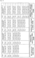
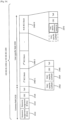
- Figure 14 illustrates an example of information content of HE-SIG-A 122 and HE-SIG-B 124 of DL PPDU 100 according to the present disclosure.
- Common control information is included in both the HE-SIG-A for non-OFDMA transmission and the HE-SIG-A for OFDMA transmission.
- the information contained in the HE-SIG-A 122 for non-OFDMA transmission differs from the HE-SIG-A 122 for OFDMA transmission.
- the HE-SIG-A field 122 contains resource assignment information and user specific information for single user transmission or multiuser MIMO transmission.
- the HE-SIG-B field 124 does not exist in case of non-OFDMA transmission in the data field 130.
- the HE-SIG-A field 122 contains resource assignment indication and user specific information for the first assignment
- the HE-SIG-B field 124 contains resource assignment indication and user specific information for each of the remaining assignments.
- common control information includes CBW and GI (Guard Interval), etc.
- the user specific information is required for each scheduled STA to decode its payload, e.g., Group ID, Nsts (i.e., the number of space-time streams) and MCS (Modulation and Coding Scheme), etc.
- common control information further includes an assignment set ID that maps a plurality of resource assignments indicated by resource assignment information to scheduled STAs, which will be detailed later.
- the common control information may further include an Allocation Defined flag in conjunction with the assignment set ID. Assume a first DL PPDU and a subsequent second DL PPDU are associated with the same assignment set ID.
- the Allocation Defined flag of the second DL PPDU shall be set if the resource assignment information contained in the first DL PPDU can be reused by the second DL PPDU. In that case, the resource assignment information for the second DL PPDU can be ommited, and thus signaling overhead can be reduced.
- the HE-SIG-A 122 contains similar information for non-OFDMA transmission and OFDMA transmission in the data field 130. This would reduce implementation complexity of STA.
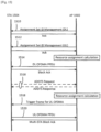
- FIG. 15 illustrates an example sequence of excuting OFDMA transmission in a radio communication system according to the present disclosure.
- the radio communication system comprises an AP 1502 and a plurality of STAs (e.g., 1504) which are associated with AP 1502, AP 1502 performs frequency scheduling using the plurality of RUs in the radio communication system.
- AP 1502 Prior to initiatation of DL OFDMA transmission, AP 1502 determines possible combinations of STAs that can be addressed by a DL OFDMA PPDU by assigning STAs to DL assignment sets and to specific assignment indices within those sets.
- One assignment set is identified by an assignment set ID and refers to a plurality of STAs and a plurality of assignment indices where each of the plurality of assignmentm indices is addressed to one or more of the plurality of STAs.
- one assignment set comprises two STAs (STA1 and STA2) and two assignments where the first assignment is addressed to STA1 and the second assignment is addressed to STA2.
- AP 1502 transmits an Assignment Set ID Management frame 1510 to STA 1504 to assign or change its assignment indices corresponding to one or more DL assignment sets of which STA 1504 is a member.
- AP 1502 Prior to initiatation of UL OFDMA transmission, AP 1502 determines the possible combinations of STAs that transmit a UL OFDMA PPDU by assigning STAs to UL assignment sets and to specific assignment indices within those sets. Then AP 1502 transmits an Assignment Set ID Management frame 1512 to STA 1504 to assign or change its assignment indices corresponding to one or more UL assignment sets of which STA 1504 is a member.
- FIG. 16 illustrates an example format of Assignment Set ID Management frame 1510 or 1512 according to the present disclosure.
- the frame 1510 comprises a Directionality field 1622, a Membership Status Array field 1624 and an Assignment Index Array field 1626.
- the Directionality field 1622 indicates whether OFDMA assignment sets are for DL or UL.
- STA 1504 may be assigned to multiple sets by setting multiple subfields of the Membership Status Array field 1624 to 1 in the frame 1510. An assignment index in each assignment set of which STA 1504 is a member is indicated by the associated subfield in the Assignment Index Array field 1626 in the frame 1510. For each Set ID, AP 1502 may assign the same assignment index to multiple STAs. STA 1504 shall have only one assignment index in each set of which it is a member.
- the AP 1502 may transmit the Assignment Set ID management frames to STA 1504 when it associates with the AP 1502. In addition, the AP 1502 may transmit the Assignment Set ID management frames to STA 1504 periodically or if necessary.
- a simple management frame can be used instead of the Assignment Set ID management frame to indicate an assignment index for each STA.
- the assignment set ID in the HE-SIG-A of DL PPDU or the trigger frame can be omitted.
- AP 1502 If AP 1502 has buffered data addressed to STA 1504, AP 1502 selects a DL assignment set of which STA 1504 is a member and determines DL resource required to transmit the data addressed to STA 1504 based on the data size and QoS (Quality of Service) requirement. Then AP 1502 transmits a DL OFDMA PPDU 1514 which includes the data addressed to STA 1504, assignment set ID of the selected DL assignment set as well as other control information (e.g., resource assignment information) which is required by STA 1504 to decode its data inside the DL OFDMA PPDU 1514.
- control information e.g., resource assignment information
- the Allocation Defined flag in the subsequent DL OFDMA PPDU shall be set and then resource assignment information needs not to be included in the subsequent DL OFDMA PPDU.
- STA 1504 may perform ADDTS Request/Response frame exchange 1516 with AP 1502 to request transmission bandwidth for its data.
- ADDTS Request frame may also include information on RUs, for example, channel quality information to show which RUs are prefereble or not prefereble for the STA 1504.
- AP 1502 selects a UL assignment set of which STA 1504 is a member and determines UL resource according to the requested transmission bandwidth by STA 1504. After that, AP 1502 transmits a trigger frame 1518 to STA 1504 which includes assignment set ID of the selected UL assignment set as well as other control information (e.g., resource assignment information) which is required by STA 1504 to transmit its data.
- the Allocation Defined flag in the subsequent trigger frame shall be set and then resource assignment information needs not to be included in the subsequent trigger frame.
- the trigger frame may also include UL transmission power control information and UL transmission duration information.
- STA 1504 After receiving the trigger frame 1518, STA 1504 transmits a UL OFDMA PPDU 1520 to send its data using the designated resource accordingly. STA 1504 may control its transmission power based on the transmission power control information so that, at the AP 1502, large variation between reception power from each STA can be avoided.
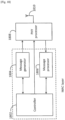
- FIG. 17 is a block diagram illustrating example configuration of AP 1502 according to the present disclosure.
- the AP 1502 comprises a controller 1702, a scheduler 1704, a message generator 1708, a message processor 1706, a PHY processor 1710 and an antenna 1712.
- the controller 1702 is a MAC protocol controller and controls general MAC protocol operations.
- scheduler 1704 For DL OFDMA transmission, scheduler 1704 performs frequency scheduling under the control of the controller 1702 based on channel quality indicators (CQIs) from STAs and assigns data for STAs to RUs. Examples of a CQI-based scheduling method include the Max CIR method and the proportional-fairness method. Scheduler 1704 also outputs the resource assignment results to the message generator 1708.
- the message generator 1708 generates corresponding common control information, resource assignment information, user specific information and data for scheduled STAs, which are formulated by the PHY processor 1710 into an OFDMA PPDU and transmitted through the antenna 1712.
- the resource assignment information can be configured according to the above mentioned embodiments.
- the message processor 1706 analyzes the received CQIs from STAs through the antenna 1712 under the control of the controller 1702 and provides them to scheduler 1704 and controller 1702. These CQIs are received quality information reported from the STAs. Further, each STA can measure received quality on a per RU basis using the received SNR, received SIR, received SINR, received CINR, received power, interference power, bit error rate, throughput and MCS whereby a predetermined error rate can be achieved. Furthermore, the CQI may also be referred to as "CSI" (Channel State Information).
- CSI Channel State Information
- scheduler 1704 For UL OFDMA transmission, scheduler 1704 performs frequency scheduling under the control of the controller 1702 based on transmission bandwidth request from STAs and assigns resource for scheduled STAs for UL data transmission. At the same time, scheduler 1704 may also perform time scheduling to determine duration of UL OFDMA frame or transmission opportunity (TXOP) in which STAs have a right to perform UL OFDMA frame exchanges. Scheduler 1704 also outputs the resource assignment results to the message generator 1708.
- the message generator 1708 generates a trigger frame including common control information, resource assignment information and user specific information, which is formulated by the PHY processor 1710 into a DL PPDU and transmitted through the antenna 1712.
- the message processor 1706 analyzes the received transmission bandwidth request from STAs through the antenna 1712 and provides them to scheduler 1704 and controller 1702.
- the antenna 1712 can be comprised of one antenna port or a combination of a plurality of antenna ports.
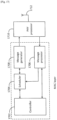
- FIG. 18 is a block diagram illustrating example configuration of STA 1504 according to the present disclosure.
- STA 1504 comprises a controller 1802, a message generator 1804, a message processor 1806, a PHY processor 1808 and an antenna 1810.
- the controller 1802 is a MAC protocol controller and controls general MAC protocol operations.
- the antenna 1810 can be comprised of one antenna port or a combination of a plurality of antenna ports.
- the message processor 1806 analyzes the received trigger frame from AP 1502 through the antenna 1810 and provides common control information, resource assignment information and user specific information to controller 1802.
- the resource assignment information can be configured according to the above mentioned embodiments.
- the message generator 1804 generates data under the control of the controller 1802, which are formulated by the PHY processor 1808 under the control of the controller 1802 into an UL OFDMA PPDU in such a way that the data is transmitted at the designated resource.
- the UL OFDMA PPDU is transmitted through the antenna 1810.
- the message processor 1806 estimates channel quality from the received DL PPDU through the antenna 1810 and provides them to controller 1802.
- the message generator 1804 generates CQI message, which is formulated by the PHY processor 1808 into an UL PPDU and transmitted through the antenna 1810.
- Figure 19 illustrates an example of resource assignment according to a fourth embodiment of the present disclosure.
- the fourth embodiment is applicable to continous resource allocation where one or more RUs that are consecutive in the frequency domain can be allocated in one assignment.
- Each assignment is addressed to either a specific STA in terms of single user transmission or a specific group of STAs in terms of multiuser MIMO transmission.
- the total number of assignments may be negotiated in advance between an AP and one or more STAs or may be explicitly signaled to each STA in the HE-SIG-A field of DL PPDU or the trigger frame.
- the start tone index of an assignment is always larger than the end tone index of its preceding assignment, there is no such restriction in the fourth embodiment.
- the start tone index and the end tone index of an assignment can be smaller than the first tone index of another preceding assignment. As a result, the scheduling flexibility is improved in the fourth embodiment.
- the resource assignment information includes a plurality of resource assignment indications, each of which corresponds to a particular assignment.
- Figure 20A illustrates a first example of resource assignment indication for one assignment according to the fourth embodiment of the present disclosure.
- the resource assignment indication for one assignment contains the number of allocated RUs, the position and type of the first allocated RU and the type of each of remaing allocated RUs.
- each resource assignment indication contains position and type information of the first RU only and type information of each of the remaining RUs.
- the start position for an assignment can be determined according to the position of the first allocated RU.
- the allocation bandwidth for the assignment can be determined according to the number of allocated RUs and the type of each of allocated RUs.
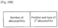
- Figure 20B illustrates a second example of resource assignment indication for one assignment according to the fourth embodiment of the present disclosure.
- the resource assignment indication for the assignment contains the number of allocated RUs and the position and type of the first allocated RU.
- the start position for an assignment can be determined according to the position of the first allocated RU.
- the allocation bandwidth for the assignment can be determined according to the number of allocated RUs and the type of the first allocated RU.
- Two-bit signaling shown in Table 1 can be used to indicate the number of allocated RUs, and three-bit signaling shown in Table 2 can be used to indicate the RU type.
- the type and position of the first allocated RU can be jointly signalled in a single signaling field as illustrated in Figure 13 .
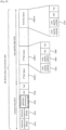
- Figure 21 illustrates another example of information content of HE-SIG-A 122 and HE-SIG-B 124 of DL PPDU according to the present disclosure.
- the HE-SIG-B field 124 does not exist in the DL PPDU in case of single user transmission.
- the HE-SIG-B field 124 exists in the DL PPDU and contains resource assignment information (i.e., resource assignment indication for each assignment), followed by user specific information for each assignment.
- the HE-SIG-B field 124 comprises two portions: HE-SIG-B1 2202 and HE-SIG-B2 2204.
- the HE-SIG-B1 2202 is transmitted over the first 20MHz subband channel 2222 and a duplicate of the HE-SIG-B 2202 is transmitted over the third 20MHz subband channel 2226 while the HE-SIG-B2 2204 is transmitted over the second 20 MHz subband channel 2224 and a duplicate of the HE-SIG-B2 2204 is transmitted over the fourth 20MHz subband channel 2228.
- resource assignment indication for one assignment that is fully located within a 20MHz subband channel should be carried in one of the HE-SIG-B1 2202 and HE-SIG-B2 2204 that is transmitted over the same 20MHz subband channel.
- the HE-SIG-B1 2202 should carry resource assignment indications for the assignments (e.g., 2212) that are fully located within the first 20MHz subband channel 2222 or the third 20MHz subband channel 2226.
- the HE-SIG-B2 2204 should carry resource assignment indications for the assignments (e.g., 2218) that are fully located within the second 20MHz subband channel 2224 or the fourth 20MHz subband channel 2228.
- the corresponding resource assignment indications can be carried either in the HE-SIG-B1 2202 or in the HE-SIG-B2 2204 such that data amount of the HE-SIG-B1 2202 and data amount of the HE-SIG-B2 2204 become similar in size. Since smaller one of the HE-SIG-B1 and the HE-SIG-B2 will be appended padding bits until their payload sizes become the same, the padding efficiency of HE-SIG-B field can be improved or maximized according to this embodiment.
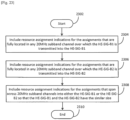
- Figure 23 is a flow chart illustrating a method for distributing resource assignment information into the HE-SIG-B field according to the present disclosure.
- the method shown in Figure 23 starts at Step 2302.
- Step 2304 resource assignment indications for the assignments that are fully located in any 20MHz subband channel over which the HE-SIG-B1 is transmitted are included (i.e., mapped) in the HE-SIG-B1.
- Step 2306 resource assignment indications for the assignments that are fully located in any 20MHz subband channel over which the HE-SIG-B2 is transmitted are included (i.e., mapped) in the HE-SIG-B2. Note that the sequential order of Step 2304 and Step 2306 may be interchangeable.
- Step 2308 resource assignment indications for the assignments that span across two or more neighboring 20MHz subband channels are included (i.e., mapped) in either the HE-SIG-B1 or the HE-SIG-B2 so that data amount of the HE-SIG-B1 and data amont of the HE-SIG-B2 become similar in size. This method stops at Step 2310.
- resource assignment indications for the above four assignments should be distributed into the HE-SIG-B as follows:
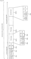
- the HE-SIG-B1 2202 or the HE-SIG-B2 2204 comprises a common field 2410 and a user-specific field 2450.
- the common field 2410 comprises a first resource assignment subfield 2412, a second resource assignment subfield 2414, a CRC (Cyclic Redundancy Check) subfield 2418 and a tail bits subfield.
- CRC Cyclic Redundancy Check
- the first resource assignment subfield 2412 contains a RU arrangement pattern index which indicates a specific RU arrangement in the frequency domain (including MU-MIMO (Multiuser Multiple Input Multiple Output) related information) for the first 20MHz subband channel 2222 in Figure 22 .
- the mapping of RU arrangement pattern indices and the corresponding RU arrangement patterns is predetermined.
- An example mapping of RU arrangement pattern indices and the corresponding RU arrangement patterns is shown in Table 5. Note that RUs are arranged from lower frequency to higher frequency in the frequency domain within a 20 MHz subband channel and Type I RUs and Type II RUs can be used for SU-MIMO transmission only.
- the first resource assignment subfield 2412 may contain a RU arrangement patern index 25 to indicate a specific RU arrangement for the first 20MHz subband channel where five Type I RUs followed by one Type III RU in the frequency domain, and each of five Type I RUs is used for SU-MIMO (Single User Multiple Input Multiple Output) transmission while the Type III RU is used for MU-MIMO transmission with two users multiplexed.
- the second resource assignment subfield 2414 indicates the RU arrangement in the frequency domain and MU-MIMO related information for the third 20MHz subband channel 2226 in Figure 22 .
- the first resource assignment subfield 2412 indicates the RU arrangement in the frequency domain and MU-MIMO related information for the second 20MHz subband channel 2224 in Figure 22 .
- the second resource assignment subfield 2414 indicates the RU arrangement in the frequency domain and MU-MIMO related information for the fourth 20MHz subband channel 2228 in Figure 22 . It should be noted that the RU arrangement signalled by the first resource assignment subfield 2412 and the second resource assignment subfield 2414 does not involve the center Type I RU 402 as illustrated in Figure 4 , which is located between two adjacent 20 MHz subband channels.
- the user-specific field 2450 comprises a plurality of BCC (Binary Convolutional Coding) blocks 2460.
- Each of the BCC blocks 2460 except the last BCC block 2460-N comprises a first user-specific subfield, a second user-specific subfield, a CRC subfield and a tail bits subfield.
- the last BCC block 2460-N may comprise a single user-specific subfield.
- Each of user-specific subfields in the user-specific field 2450 carries per-user allocation information (e.g., STA identifier for addressing and the information necessary for decoding the PPDU 100 such as the number of spatial streams and modulation and coding scheme, etc).
- each RU assigned for SU-MIMO transmission there is only a single corresponding user-specific subfield.
- the ordering of user-specific subfields in the user-specific field 2450 is compliant with the RU arrangement signalled by the first resource assignment subfield 2412 and the second resource assignment subfield 2414.
- one of the user-specific subfields of the user-specific field 2450 in each of the HE-SIG-B1 2022 and the HE-SIG-B2 2024 is used to carry per-user allocation information for the center Type I RU 402 as illustrated in Figure 4 .
- the user-specific subfield for the center Type I RU shall be located at a predetermined position in the user-specific field 2450.
- the user-specific subfield for the center Type I RU is the last user-specific subfield 2470 in the user-specific field 2450.
- the number of the user-specific subfields in the user-specific field 2450 except the user-specific subfield for the center Type I RU can be derived from the first resource assignment subfield 2412 and the second resource assignment subfield 2414 in the common field 2410.
- CBW 160 MHz or 80+80 MHz
- there are two center Type-I RUs in total in case of CBW 160 MHz or 80+80 MHz.
- two of the user-specific subfields of the user-specific field 2450 in each of the HE-SIG-B1 2022 and the HE-SIG-B2 2024 are used to carry per-user allocation information for the two center Type I RUs, respectively.
- Each of the two user-specific subfields for the center Type I RUs shall be located at a predetermined position in the user-specific field 2450.
- the user-specific subfield for a first center Type I RU is the last user-specific subfield in the user-specific field 2450 while the user-specific subfield for a second center Type I RU is the second last user-specific subfield in the user-specific field 2450.
- the HE-SIG-B1 2202 or the HE-SIG-B2 2204 comprises a common field 2510 and a user-specific field 2550.
- the common field 2510 comprises a first resource assignment subfield 2512, a second resource assignment subfield 2514, a presence of allocation information for center RU subfield 2516, a CRC subfield 2518 and a tail bits subfield.
- the user-specific field 2550 comprises a plurality of BCC blocks 2560.
- Each of the BCC blocks 2560 except the last BCC block 2560-N comprises a first user-specific subfield, a second user-specific subfield, a CRC subfield and a tail bits subfield.
- the last BCC block 2560-N may comprise a single user-specific subfield.
- Each of the user-specific subfields in the user-specific field 2450 carries per-user allocation information.
- the first resource assignment subfield 2512, the second resource assignment subfield 2514 and each of user-specific subfields are defined in the same way as their respective counterparts in Figure 24 .
- the presence of allocation information for center RU subfield 2516 in the common field 2510 is used to indicate whether there is a user-specific subfield for the center Type I RU in the user-specific field 2550. If a user-specific subfield for the center Type I RU is present in the user-specific field 2550, its position in the user-specific field 2550 shall be predetermined. For example, the user-specific subfield for the center Type I RU is the last user-specific subfield 2570 in the user-specific field 2550.
- the number of user-specific subfields in the user-specific field 2550 can be derived from the first resource assignment subfield 2512, the second resource assignment subfield 2514 and the presence of allocation information for center RU subfield 2516 in the common field 2510.
- the second example format as illustrated in Figure 25 enables more flexible arrangement of user-specific subfield for the center Type I RU in the HE-SIG-B1 2202 and the HE-SIG-B2 2204.
- the user-specific subfield for the center Type I RU may be included in either of the HE-SIG-B1 2202 and the HE-SIG-B2 2204 for the purpose of keeping load balancing between the HE-SIG-B1 2202 and the HE-SIG-B2 2204 and improving channel efficiency.
- the user-specific subfield for the center Type I RU may be included in either of the HE-SIG-B1 2202 and the HE-SIG-B2 2204 so that the difference in terms of the number of user-specific subfields between the HE-SIG-B1 2202 and the HE-SIG-B2 2204 is minimized.
- the user-specific subfield for the center Type I RU may be included in both of the HE-SIG-B1 2202 and the HE-SIG-B2 2204 for the purpose of improving reliability for decoding the user-specific subfield for the center Type I RU.
- the presence of allocation information for center RU subfield 2516 in the common field 2510 needs to indicate whether there is a user-specific subfield for each of the two center Type I RUs in the user-specific field 2550. If the user-specific subfield for only one of the two center Type I RUs is present in the user-specific field 2550, its position in the user-specific field 2550 shall be predetermined. For example, the user-specific subfield for the center Type I RU is the last user-specific subfield in the user-specific field 2550.
- the two user-specific subfields for the center Type I RUs shall be located at the predetermined positions in the user-specific field 2550.
- the user-specific subfield for a first center Type I RU is the last user-specific subfield in the user-specific field 2550 while the user-specific subfield for a second center Type I RU is the second last user-specific subfield in the user-specific field 2550.
- the HE-SIG-B1 2202 or the HE-SIG-B2 2204 comprises a common field 2610 and a user-specific field 2650.
- the common field 2610 comprises a first resource assignment subfield 2612, a second resource assignment subfield 2614, a CRC subfield 2618 and a tail bits subfield.
- the user-specific field 2650 comprises a plurality of BCC blocks 2660.
- Each of BCC blocks 2660 except the last BCC block 2660-N comprises a first user-specific subfield, a second user-specific subfield, a CRC subfield and a tail bits subfield.
- the last BCC block 2660-N may comprise a single user-specific subfield.
- Each of user-specific subfields in the user-specific field 2650 carries per-user allocation information.
- the first resource assignment subfield 2612, the second resource assignment subfield 2614 and each of user-specific subfields are defined in the same way as their respective counterparts in Figure 24 .
- whether the CRC subfield 2618 in the common field 2610 is masked by a predefined binary sequence i.e., whether a XOR (Exclusive OR) is applied to the CRC subfield 2618 and a predefined binary sequence
- a predefined binary sequence i.e., whether a XOR (Exclusive OR) is applied to the CRC subfield 2618 and a predefined binary sequence
- a predefined binary sequence i.e., whether a XOR (Exclusive OR) is applied to the CRC subfield 2618 and a predefined binary sequence
- whether the CRC subfield of a specific BCC block in the user-specific field 2650 is masked by a predefined binary sequence is used to indicate whether there is a user-specific subfield for the center Type I RU in the user-specific field 2650. For example, if the CRC subfield 2666 of the first BCC block 2660-1 is not masked by a predefined binary sequence, there is no user-specific subfield for the center Type I RU in the user-specific field 2650. Otherwise there is a user-specific subfield for the center Type I RU in the user-specific field 2650.
- a user-specific subfield for the center Type I RU is present in the user-specific field 2650, its position in the user-specific field 2650 shall be predetermined.
- the user-specific subfield for the center Type I RU is the last user-specific subfield 2670 in the user-specific field 2650.
- the number of user-specific subfields in the user-specific field 2650 except the user-specific subfield for the center Type I RU can be derived from the first resource assignment subfield 2612 and the second resource assignment subfield 2614 in the common field 2610.
- the third example format as illustrated in Figure 26 does not need a signaling subfield in the common field to signal the presence of user-specific subfield for the center Type I RU in the user-specific field.
- the signaling bits required by the third example format is reduced compared with the second example format.
- whether the CRC subfield 2618 in the common field 2610 (or the CRC subfield 2666 in the user-specific field 2650) is masked by one of the three predefined binary sequences is used to indicate whether there is a user-specific subfield for each of the two center Type I RUs in the user-specific field 2650. For example, if the CRC subfield 2618 in the common field 2610 (or the CRC subfield 2666 in the user-specific field 2650) is not masked by one of three predefined binary sequences, there is no user-specific subfield for the center Type I RU in the user-specific field 2650.
- the CRC subfield 2618 in the common field 2610 (or the CRC subfield 2666 in the user-specific field 2650) is masked by a first predefined binary sequence, there is a user-specific subfield for a first center Type I RU in the user-specific field 2650. If the CRC subfield 2618 in the common field 2610 (or the CRC subfield 2666 in the user-specific field 2650) is masked by a second predefined binary sequence, there is a user-specific subfield for a second center Type I RU in the user-specific field 2650.
- the CRC subfield 2618 in the common field 2610 (or the CRC subfield 2666 in the user-specific field 2650) is masked by a third predefined binary sequence, there is a user-specific subfield for each of the two center Type I RUs in the user-specific field 2650. If the user-specific subfield for only one of the two center Type I RUs is present in the user-specific field 2650, its position in the user-specific field 2650 shall be predetermined. For example, the user-specific subfield for the center Type I RU is the last user-specific subfield in the user-specific field 2650.
- the two user-specific subfields for the center Type I RUs shall be located at the predetermined positions in the user-specific field 2650.
- the user-specific subfield for a first center Type I RU is the last user-specific subfield in the user-specific field 2650; while the user-specific subfield for a second center Type I RU is the second last user-specific subfield in the user-specific field 2650.
- the present invention is configured with hardware by way of example, but the invention may also be provided by software in cooperation with hardware.
- the functional blocks used in the descriptions of the embodiments are typically implemented as LSI devices, which are integrated circuits.
- the functional blocks may be formed as individual chips, or a part or all of the functional blocks may be integrated into a single chip.
- LSI is used herein, but the terms "IC,” “system LSI,” “super LSI” or “ultra LSI” may be used as well depending on the level of integration.
- circuit integration is not limited to LSI and may be achieved by dedicated circuitry or a general-purpose processor other than an LSI.
- a field programmable gate array FPGA
- reconfigurable processor which allows reconfiguration of connections and settings of circuit cells in LSI may be used.
- This disclosure can be applied to a method for formatting and transmitting resource assignment information in a wireless communications system.
Landscapes
- Engineering & Computer Science (AREA)
- Signal Processing (AREA)
- Computer Networks & Wireless Communication (AREA)
- Databases & Information Systems (AREA)
- Quality & Reliability (AREA)
- Mobile Radio Communication Systems (AREA)
- Time-Division Multiplex Systems (AREA)
- Communication Control (AREA)
Applications Claiming Priority (6)
| Application Number | Priority Date | Filing Date | Title |
|---|---|---|---|
| JP2015132790 | 2015-07-01 | ||
| JP2015170508 | 2015-08-31 | ||
| JP2015216775 | 2015-11-04 | ||
| EP24152731.6A EP4333332B1 (de) | 2015-07-01 | 2016-06-15 | Übertragungsvorrichtung und übertragungsverfahren für ressourcenzuweisungsinformationen |
| EP16817426.6A EP3317985B1 (de) | 2015-07-01 | 2016-06-15 | Übertragungsvorrichtung und übertragungsverfahren von ressourcenzuweisungsinformationen |
| PCT/JP2016/002882 WO2017002314A1 (en) | 2015-07-01 | 2016-06-15 | Transmission apparatus and transmission method of resource assignment information |
Related Parent Applications (3)
| Application Number | Title | Priority Date | Filing Date |
|---|---|---|---|
| EP24152731.6A Division-Into EP4333332B1 (de) | 2015-07-01 | 2016-06-15 | Übertragungsvorrichtung und übertragungsverfahren für ressourcenzuweisungsinformationen |
| EP24152731.6A Division EP4333332B1 (de) | 2015-07-01 | 2016-06-15 | Übertragungsvorrichtung und übertragungsverfahren für ressourcenzuweisungsinformationen |
| EP16817426.6A Division EP3317985B1 (de) | 2015-07-01 | 2016-06-15 | Übertragungsvorrichtung und übertragungsverfahren von ressourcenzuweisungsinformationen |
Publications (2)
| Publication Number | Publication Date |
|---|---|
| EP4557641A2 true EP4557641A2 (de) | 2025-05-21 |
| EP4557641A3 EP4557641A3 (de) | 2025-08-13 |
Family
ID=57608272
Family Applications (3)
| Application Number | Title | Priority Date | Filing Date |
|---|---|---|---|
| EP24152731.6A Active EP4333332B1 (de) | 2015-07-01 | 2016-06-15 | Übertragungsvorrichtung und übertragungsverfahren für ressourcenzuweisungsinformationen |
| EP25168314.0A Pending EP4557641A3 (de) | 2015-07-01 | 2016-06-15 | Übertragungsvorrichtung und übertragungsverfahren für ressourcenzuweisungsinformationen |
| EP16817426.6A Active EP3317985B1 (de) | 2015-07-01 | 2016-06-15 | Übertragungsvorrichtung und übertragungsverfahren von ressourcenzuweisungsinformationen |
Family Applications Before (1)
| Application Number | Title | Priority Date | Filing Date |
|---|---|---|---|
| EP24152731.6A Active EP4333332B1 (de) | 2015-07-01 | 2016-06-15 | Übertragungsvorrichtung und übertragungsverfahren für ressourcenzuweisungsinformationen |
Family Applications After (1)
| Application Number | Title | Priority Date | Filing Date |
|---|---|---|---|
| EP16817426.6A Active EP3317985B1 (de) | 2015-07-01 | 2016-06-15 | Übertragungsvorrichtung und übertragungsverfahren von ressourcenzuweisungsinformationen |
Country Status (13)
| Country | Link |
|---|---|
| US (5) | US10805912B2 (de) |
| EP (3) | EP4333332B1 (de) |
| JP (4) | JP6628112B2 (de) |
| KR (3) | KR102711589B1 (de) |
| CN (2) | CN110351063B (de) |
| BR (1) | BR112017023733B1 (de) |
| CA (2) | CA3207631A1 (de) |
| CO (1) | CO2017012701A2 (de) |
| ES (1) | ES2989778T3 (de) |
| MX (1) | MX2017013796A (de) |
| MY (1) | MY181052A (de) |
| RU (1) | RU2704627C2 (de) |
| WO (1) | WO2017002314A1 (de) |
Families Citing this family (23)
| Publication number | Priority date | Publication date | Assignee | Title |
|---|---|---|---|---|
| US10582025B2 (en) * | 2015-05-05 | 2020-03-03 | Samsung Electronics Co., Ltd. | Efficient signaling and addressing in wireless local area network systems |
| CN113992248B (zh) | 2015-05-05 | 2024-02-02 | 三星电子株式会社 | 识别/指示无线局域网中的调度信息的装置和方法 |
| US10505691B2 (en) * | 2015-08-20 | 2019-12-10 | Lg Electronics Inc. | Method and apparatus for configuring frame unit comprising control field indicating data fields in wireless LAN system |
| US11245499B2 (en) * | 2018-06-22 | 2022-02-08 | Qualcomm Incorporated | Signaling overhead reduction in NOMA |
| CN116388943B (zh) * | 2018-07-25 | 2024-03-15 | 华为技术有限公司 | 资源单元指示方法、装置及存储介质 |
| US10855428B2 (en) * | 2018-11-29 | 2020-12-01 | Cisco Technology, Inc. | Reducing channel sounding overhead using uplink OFDMA transmissions |
| JP7338998B2 (ja) * | 2019-03-14 | 2023-09-05 | 株式会社Nttドコモ | 無線通信システム及び制御方法 |
| CN112398888B (zh) * | 2019-08-15 | 2023-02-28 | 北京华为数字技术有限公司 | 一种通信方法及装置 |
| BR112022003012A2 (pt) * | 2019-08-23 | 2022-05-10 | Beijing Xiaomi Mobile Software Co Ltd | Método, aparelho e dispositivo para alocar um recurso de comunicação, e, meio de armazenamento legível por computador não transitório |
| US11438968B2 (en) * | 2019-10-29 | 2022-09-06 | Intel Corporation | Non-contiguous resource units for wireless local-area networks (WLANs) |
| JP7527772B2 (ja) * | 2019-11-07 | 2024-08-05 | キヤノン株式会社 | 通信装置、制御方法、およびプログラム |
| CN118573328A (zh) * | 2020-03-13 | 2024-08-30 | 松下电器(美国)知识产权公司 | 用于多个资源单元的组合上的传输的通信装置和通信方法 |
| CN117097450A (zh) * | 2020-03-13 | 2023-11-21 | 华为技术有限公司 | 一种资源单元合并指示方法及通信装置 |
| US12081469B2 (en) * | 2020-03-23 | 2024-09-03 | Qualcomm Incorporated | Multi-generation communication in a wireless local area network (WLAN) |
| CN113517974B (zh) * | 2020-04-10 | 2023-03-28 | 华为技术有限公司 | 一种多资源单元对应的调制方式的指示方法及相关设备 |
| CN121000571A (zh) * | 2020-04-29 | 2025-11-21 | Lg 电子株式会社 | 用于80mhz的导频信号 |
| US11791970B2 (en) * | 2020-06-09 | 2023-10-17 | Mediatek Inc. | Intra-PPDU resource reallocation for multiple users |
| EP4173411A4 (de) * | 2020-06-26 | 2023-12-13 | Panasonic Intellectual Property Corporation of America | Kommunikationsvorrichtung und kommunikationsverfahren zur signalisierung der ressourceneinheitszuweisung |
| US12355706B2 (en) * | 2020-07-01 | 2025-07-08 | Samsung Electronics Co., Ltd. | Apparatus and method for communication based on multi-resource unit in wireless local area network system |
| US20210329637A1 (en) * | 2020-07-17 | 2021-10-21 | Intel Corporation | Methods and arrangements for large resource unit allocation |
| US20230179332A1 (en) * | 2021-12-06 | 2023-06-08 | Mediatek Singapore Pte. Ltd. | Detailed Signaling Designs For Distributed-Tone Resource Unit Transmission |
| TWI819591B (zh) * | 2022-05-04 | 2023-10-21 | 瑞昱半導體股份有限公司 | 執行內容通道產生的裝置及方法 |
| TWI801232B (zh) | 2022-05-04 | 2023-05-01 | 瑞昱半導體股份有限公司 | 處理負載平衡的電路及方法 |
Family Cites Families (32)
| Publication number | Priority date | Publication date | Assignee | Title |
|---|---|---|---|---|
| RU2313912C2 (ru) * | 2003-06-27 | 2007-12-27 | Нокиа Корпорейшн | Способ и устройство для агрегирования пакетов в сети беспроводной связи |
| US8519225B2 (en) * | 2006-02-10 | 2013-08-27 | Monsanto Technology Llc | Identification and use of target genes for control of plant parasitic nematodes |
| CN101242239B (zh) * | 2007-02-09 | 2012-05-23 | 电信科学技术研究院 | 实现上行跳频传输的方法、系统和终端 |
| US8982889B2 (en) * | 2008-07-18 | 2015-03-17 | Marvell World Trade Ltd. | Preamble designs for sub-1GHz frequency bands |
| US8867574B2 (en) | 2010-06-02 | 2014-10-21 | Qualcomm Incorporated | Format of VHT-SIG-B and service fields in IEEE 802.11AC |
| US9860037B2 (en) * | 2010-07-21 | 2018-01-02 | Qualcomm, Incorporated | Method and apparatus for ordering sub-fields of VHT-SIG-A and VIT-SIG-B fields |
| KR101424368B1 (ko) * | 2010-11-26 | 2014-08-01 | 엘지전자 주식회사 | 무선랜 시스템에서 링크 적응을 기반으로 한 채널 정보 보고 방법 및 이를 지원하는 장치 |
| US9667377B2 (en) * | 2011-04-08 | 2017-05-30 | Futurewei Technologies, Inc. | Wavelength indication in multiple-wavelength passive optical networks |
| JP5961853B2 (ja) * | 2011-04-27 | 2016-08-02 | シャープ株式会社 | 端末、基地局、通信システムおよび通信方法 |
| US9203586B2 (en) * | 2011-06-15 | 2015-12-01 | Lg Electronics Inc. | Method for transmitting and receiving data unit based on uplink multiple user multiple input multiple output transmission and apparatus for the same |
| US10439773B2 (en) * | 2013-04-15 | 2019-10-08 | Qualcomm Incorporated | Systems and methods for backwards-compatible preamble formats for multiple access wireless communication |
| CA2911262C (en) | 2013-05-07 | 2020-06-30 | Lg Electronics Inc. | Method and device for transmitting data unit |
| EP3072247A4 (de) * | 2013-11-19 | 2017-08-23 | Intel IP Corporation | Framestruktur mit reduziertem signalfeld und verfahren für hocheffiziente wifi (hew)-kommunikation |
| US9755795B2 (en) * | 2013-12-18 | 2017-09-05 | Huawei Technologies Co., Ltd. | System and method for WLAN OFDMA design of subcarrier groups and frame format |
| US10038535B2 (en) * | 2014-04-09 | 2018-07-31 | Lg Electronics Inc. | Method and apparatus for transmitting frame on basis of sounding procedure |
| US9954663B2 (en) * | 2014-05-09 | 2018-04-24 | Huawei Technologies Co., Ltd. | System and method for orthogonal frequency division multiple access communications |
| EP3902192B1 (de) * | 2014-06-12 | 2023-05-03 | Huawei Technologies Co., Ltd. | System und verfahren für ofdma-tonzuweisung in wifi-netzwerken der nächsten generation |
| US20150365923A1 (en) * | 2014-06-17 | 2015-12-17 | Qualcomm Incorporated | Methods and apparatus for signaling user allocations in mixed multi-user wireless communication networks |
| EP3611901B1 (de) * | 2014-06-27 | 2022-03-23 | Samsung Electronics Co., Ltd. | Verfahren und vorrichtung zur übertragung von daten |
| WO2016021819A1 (ko) | 2014-08-04 | 2016-02-11 | 엘지전자 주식회사 | 서로 다른 길이의 가드 인터벌을 포함하는 데이터 단위를 전송하는 방법 및 장치 |
| EP3182632B1 (de) * | 2014-08-14 | 2020-07-22 | LG Electronics Inc. | Verfahren und vorrichtung zur zuweisung von funkressourcen zur vermeidung von störungen in einem wlan |
| US10693532B2 (en) * | 2014-09-03 | 2020-06-23 | Newracom, Inc. | Operation method of station in wireless local area network |
| WO2016057292A1 (en) | 2014-10-07 | 2016-04-14 | Intel Corporation | Parallel transmission of high efficiency signal field |
| CN104363192B (zh) * | 2014-10-21 | 2017-10-31 | 江苏中兴微通信息科技有限公司 | 一种兼容多种帧格式的mimo通信系统的接收方法和装置 |
| US9756626B2 (en) * | 2014-11-13 | 2017-09-05 | Intel IP Corporation | High-efficiency Wi-Fi (HEW) station and access point (AP) and method for signaling of channel resource allocations |
| US10469631B2 (en) * | 2014-11-21 | 2019-11-05 | Newracom, Inc. | Systems and methods for multi-user resource assignments |
| US9955469B2 (en) * | 2015-02-27 | 2018-04-24 | Intel Corporation | Joint encoding of wireless communication allocation information |
| US9980284B2 (en) * | 2015-03-13 | 2018-05-22 | Huawei Technologies Co., Ltd. | Contention-based reservations of network resources |
| US10389563B2 (en) * | 2015-05-05 | 2019-08-20 | Intel IP Corporation | Systems and methods for Wi-Fi high efficiency preambles for resource unit allocation |
| US20160366688A1 (en) * | 2015-06-10 | 2016-12-15 | Xiaogang Chen | Optimizing wireless network communications |
| US10305643B2 (en) * | 2015-06-24 | 2019-05-28 | Apple Inc. | Wireless preamble structure for OFDMA signaling under OBSS interference |
| US9743393B2 (en) * | 2015-06-25 | 2017-08-22 | Intel IP Corporation | Dynamic patterned resource allocation in a wireless network |
-
2016
- 2016-06-15 KR KR1020247015268A patent/KR102711589B1/ko active Active
- 2016-06-15 MX MX2017013796A patent/MX2017013796A/es active IP Right Grant
- 2016-06-15 RU RU2017134588A patent/RU2704627C2/ru active
- 2016-06-15 CN CN201910634775.7A patent/CN110351063B/zh active Active
- 2016-06-15 KR KR1020177030249A patent/KR102609774B1/ko active Active
- 2016-06-15 WO PCT/JP2016/002882 patent/WO2017002314A1/en not_active Ceased
- 2016-06-15 EP EP24152731.6A patent/EP4333332B1/de active Active
- 2016-06-15 CA CA3207631A patent/CA3207631A1/en active Pending
- 2016-06-15 KR KR1020237041308A patent/KR102665657B1/ko active Active
- 2016-06-15 CA CA2982754A patent/CA2982754C/en active Active
- 2016-06-15 ES ES16817426T patent/ES2989778T3/es active Active
- 2016-06-15 CN CN201680023569.7A patent/CN107534502B/zh active Active
- 2016-06-15 JP JP2017558768A patent/JP6628112B2/ja active Active
- 2016-06-15 BR BR112017023733-4A patent/BR112017023733B1/pt active IP Right Grant
- 2016-06-15 EP EP25168314.0A patent/EP4557641A3/de active Pending
- 2016-06-15 EP EP16817426.6A patent/EP3317985B1/de active Active
- 2016-06-15 MY MYPI2017704170A patent/MY181052A/en unknown
-
2017
- 2017-10-23 US US15/790,875 patent/US10805912B2/en active Active
- 2017-12-12 CO CONC2017/0012701A patent/CO2017012701A2/es unknown
-
2019
- 2019-11-19 JP JP2019208880A patent/JP6956356B2/ja active Active
-
2020
- 2020-09-10 US US17/017,300 patent/US11589341B2/en active Active
-
2021
- 2021-09-14 JP JP2021149300A patent/JP7149654B2/ja active Active
-
2022
- 2022-09-15 JP JP2022147024A patent/JP7580058B2/ja active Active
-
2023
- 2023-01-17 US US18/155,637 patent/US11889529B2/en active Active
- 2023-12-04 US US18/528,324 patent/US12144005B2/en active Active
-
2024
- 2024-10-02 US US18/904,753 patent/US20250031214A1/en active Pending
Also Published As
Similar Documents
| Publication | Publication Date | Title |
|---|---|---|
| US12144005B2 (en) | Transmission apparatus and transmission method of resource assignment information | |
| KR102622832B1 (ko) | 송신 장치 및 송신 방법 | |
| JP7642047B2 (ja) | 通信装置及び通信方法 |
Legal Events
| Date | Code | Title | Description |
|---|---|---|---|
| PUAI | Public reference made under article 153(3) epc to a published international application that has entered the european phase |
Free format text: ORIGINAL CODE: 0009012 |
|
| STAA | Information on the status of an ep patent application or granted ep patent |
Free format text: STATUS: REQUEST FOR EXAMINATION WAS MADE |
|
| 17P | Request for examination filed |
Effective date: 20250403 |
|
| AC | Divisional application: reference to earlier application |
Ref document number: 3317985 Country of ref document: EP Kind code of ref document: P Ref document number: 4333332 Country of ref document: EP Kind code of ref document: P |
|
| AK | Designated contracting states |
Kind code of ref document: A2 Designated state(s): AL AT BE BG CH CY CZ DE DK EE ES FI FR GB GR HR HU IE IS IT LI LT LU LV MC MK MT NL NO PL PT RO RS SE SI SK SM TR |
|
| REG | Reference to a national code |
Ref country code: DE Ref legal event code: R079 Free format text: PREVIOUS MAIN CLASS: H04J0011000000 Ipc: H04L0005000000 |
|
| PUAL | Search report despatched |
Free format text: ORIGINAL CODE: 0009013 |
|
| AK | Designated contracting states |
Kind code of ref document: A3 Designated state(s): AL AT BE BG CH CY CZ DE DK EE ES FI FR GB GR HR HU IE IS IT LI LT LU LV MC MK MT NL NO PL PT RO RS SE SI SK SM TR |
|
| RIC1 | Information provided on ipc code assigned before grant |
Ipc: H04L 5/00 20060101AFI20250708BHEP |
|
| RIC1 | Information provided on ipc code assigned before grant |
Ipc: H04L 5/00 20060101AFI20251002BHEP |
|
| GRAP | Despatch of communication of intention to grant a patent |
Free format text: ORIGINAL CODE: EPIDOSNIGR1 |
|
| STAA | Information on the status of an ep patent application or granted ep patent |
Free format text: STATUS: GRANT OF PATENT IS INTENDED |
|
| INTG | Intention to grant announced |
Effective date: 20251110 |