EP4557583A1 - Elektrische maschine mit anschlüssen - Google Patents
Elektrische maschine mit anschlüssen Download PDFInfo
- Publication number
- EP4557583A1 EP4557583A1 EP24209739.2A EP24209739A EP4557583A1 EP 4557583 A1 EP4557583 A1 EP 4557583A1 EP 24209739 A EP24209739 A EP 24209739A EP 4557583 A1 EP4557583 A1 EP 4557583A1
- Authority
- EP
- European Patent Office
- Prior art keywords
- support
- connecting element
- electrical machine
- leg
- housing
- Prior art date
- Legal status (The legal status is an assumption and is not a legal conclusion. Google has not performed a legal analysis and makes no representation as to the accuracy of the status listed.)
- Withdrawn
Links
Images

Classifications
-
- H—ELECTRICITY
- H02—GENERATION; CONVERSION OR DISTRIBUTION OF ELECTRIC POWER
- H02K—DYNAMO-ELECTRIC MACHINES
- H02K3/00—Details of windings
- H02K3/46—Fastening of windings on the stator or rotor structure
- H02K3/52—Fastening salient pole windings or connections thereto
- H02K3/521—Fastening salient pole windings or connections thereto applicable to stators only
- H02K3/522—Fastening salient pole windings or connections thereto applicable to stators only for generally annular cores with salient poles
-
- H—ELECTRICITY
- H02—GENERATION; CONVERSION OR DISTRIBUTION OF ELECTRIC POWER
- H02K—DYNAMO-ELECTRIC MACHINES
- H02K5/00—Casings; Enclosures; Supports
- H02K5/04—Casings or enclosures characterised by the shape, form or construction thereof
- H02K5/22—Auxiliary parts of casings not covered by groups H02K5/06-H02K5/20, e.g. shaped to form connection boxes or terminal boxes
- H02K5/225—Terminal boxes or connection arrangements
-
- H—ELECTRICITY
- H02—GENERATION; CONVERSION OR DISTRIBUTION OF ELECTRIC POWER
- H02K—DYNAMO-ELECTRIC MACHINES
- H02K2203/00—Specific aspects not provided for in the other groups of this subclass relating to the windings
- H02K2203/06—Machines characterised by the wiring leads, i.e. conducting wires for connecting the winding terminations
-
- H—ELECTRICITY
- H02—GENERATION; CONVERSION OR DISTRIBUTION OF ELECTRIC POWER
- H02K—DYNAMO-ELECTRIC MACHINES
- H02K5/00—Casings; Enclosures; Supports
- H02K5/24—Casings; Enclosures; Supports specially adapted for suppression or reduction of noise or vibrations
Definitions
- the present invention relates to an electrical machine.
- the electrical machine in particular, features improvements regarding the vibration resistance of internal electrical conductors.
- connection elements designed to make electrical contact with an inverter.
- the connection elements can, for example, be permanently attached to a housing of the electrical machine. This serves to easily and reliably fasten and electrically contact the inverter's terminals.
- the connection elements are connected to a winding of the electrical machine via connecting elements.
- the connecting elements or connection elements have at least flexible sections designed to compensate for tolerances between the winding and the connection element.
- the electrical machine according to the invention has improved vibration resistance of internal electrical connection elements.
- the risk of vibration fractures of internal connection elements is reduced or eliminated in this way.
- the electrical machine has a stator with a multi-phase electrical winding.
- the winding in turn, has at least one phase strand.
- the electrical winding has three phase strands.
- the stator is arranged within a housing of the electrical machine.
- the housing has an opening for the implementation of an electrical connection.
- at least one electrically conductive connection element is provided.
- the connection element is designed to connect one of the phase strands to the phase of an external power supply.
- the external power supply can in particular be an inverter. It is therefore advantageously provided that one connection element is provided for each phase strand of the winding.
- all connection elements are attached or fixed to the housing.
- the at least one connection element is advantageously located on a different side of the housing than the stator.
- the electrical machine further comprises at least one electrically conductive connecting element.
- the connecting element extends between one end of one of the phase strands of the winding and the connecting element.
- the electrically conductive connecting element connects the phase strand to the connecting element.
- the connecting element is designed to be elastic in order to achieve tolerance compensation and/or movement compensation between the stator and the connecting element. It is particularly advantageous that a separate connecting element and a separate connecting element are provided for each phase strand. In the above-mentioned exemplary design with three phase strands of the electrical winding, three connecting elements and three connecting elements are thus provided, with each phase strand being electrically connected to a separate connecting element via its own connecting element.
- the electrically conductive connecting element extends through the opening in the housing. This allows the stator and connection elements to be arranged on different sides of the housing. In particular, the stator can be shielded from external influences by the housing.
- the at least one connecting element and/or the connecting element is supported in a vibration-damping manner by means of a support part arranged in the opening of the housing.
- the vibration damping is advantageously achieved by increasing the Natural frequency of the connecting element and/or the connecting element due to the support on the housing by the support part.
- the support part reduces the vibration path of the connecting element and/or the connecting element through mechanical fixation.
- the support part preferably has at least one first support contour for supporting the connecting element and/or the connecting element.
- the first support contour rests against the connecting element and/or the connecting element and thus provides said vibration-damping support.
- a first support contour is provided for each connecting element and/or the connecting element.
- the first support contour can be designed, for example, as a projection or as a protruding arm.
- the support part has at least a second support contour.
- the second support contour is designed to support the connection element and/or connecting element.
- the second support contour is designed opposite the first support contour.
- the connection element and/or the connecting element are advantageously arranged between the first support contour and the second support contour.
- it is provided that the connection element and/or the connecting element are clamped between the first support contour and the second support contour.
- the second support contour is advantageously designed analogously to the first support contour.
- the second support contour is advantageously designed as a projection and/or as a protruding arm.
- the second support contour and the first support contour can thus support a connecting element and/or connection element from two sides. This is particularly advantageous if the connection element and/or connecting element are designed as a flat conductor.
- Such a design of the connection element and/or connecting element is an advantageous embodiment of the electrical machine.
- the first support contour and/or the second support contour preferably have a single or multiple linear contact with the respective connecting element or connecting element. This is achieved in particular by the first support contour and/or the second support contour having a wave shape and/or a sawtooth shape in order to come into contact with the respective surface of the connecting element and/or connecting element with this shape. In this way, in particular, full-surface contact of the support contour or the support contours is avoided. This achieves a defined contact of the support part on the connecting element and/or the connecting element.
- the support part has a third support contour.
- the third support contour extends outward and bears against the housing. "Extending outward" means, in particular, that the third support contour extends away from the connection element and/or the connecting element. This provides support for the support part relative to the housing, thereby optimizing the vibration damping of the connection and/or connecting element.
- the third support contour has a linear contact with the housing.
- the linear contact can be single or multiple.
- a wave shape and/or a sawtooth shape is particularly advantageously provided to achieve contact between the third support contour and the housing. This, in turn, leads to an advantageously defined connection of the third support contour to the housing.
- the support part has a base body.
- the base body is in particular annular or C-shaped.
- a C-shape refers in particular to an open ring shape, wherein the C-shape can be achieved by a rounded body and/or by several segments of a body that are angled towards one another.
- the base body surrounds the connecting element and/or the connecting element at least partially.
- the base body has a first leg, a second leg and a third leg connecting the first leg and the second leg.
- the first leg and the second leg preferably have a free end, wherein this shape advantageously allows for elastic bending of the first leg and second leg. This simplifies the assembly of the support part and/or the connecting element and/or the connection element.
- the at least one first support contour is preferably attached to the first leg.
- the aforementioned at least one second support contour is preferably attached to the second leg. It is advantageously provided that an equal number of first support contours and third support contours are arranged on the first leg. Alternatively or additionally, it is preferably provided that an equal number of second support contours and third support contours are arranged on the second leg.
- the third support contours extend from the first leg preferably in opposite directions to the first support contours.
- the third support contours extend from the second leg preferably in opposite directions to the second support contours.
- the support part has at least a fourth support contour.
- the fourth support contour extends outwards from the third leg.
- the fourth support contour rests against the housing, particularly advantageously via a single or multiple line contact.
- the single or multiple line contact is achieved in particular via a sawtooth shape and/or wave shape of the fourth support contour.
- no support contours extend inwards from the third leg, i.e., no support contours extend to the connection element and/or connecting element.
- the third leg, from which the at least one fourth support contour extends serves only to connect the first leg and second leg and to arrange the support part within the opening of the housing.
- the support part can advantageously be inserted into the opening in the housing along an axial direction of the electrical machine.
- the axial direction of the electrical machine is in particular the axial direction of the rotor and/or stator of the electrical machine.
- the axial direction runs in particular parallel to a central axis of the rotor and/or stator of the electrical machine.
- the support part has at least one axial stop, by which an end position of the support part in the housing is defined in the axial direction. Installation of the support part is thus simple and requires little effort.
- the support part is also reliably arranged within the opening.
- the connecting element is advantageously part of a conductor rail.
- the conductor rail interconnects conductor strands of winding 3.
- Winding 3 is advantageously formed by U-shaped and/or I-shaped conductor sections, the ends of which are interconnected by the conductor rail to form the winding.
- each phase strand of the winding is interconnected by a conductor rail.
- each connecting element is part of its own conductor rail.
- the support part is advantageously designed to be electrically insulating.
- the support part is made of an electrically insulating material. This prevents the support part from causing a short circuit between the individual phase strands of the winding.
- connection element preferably has a contact section for electrically contacting the phase of the external power supply and a flexible section for elastic connection to the connecting element.
- the flexible section preferably has a multiplicity of stranded wires or a multiplicity of lamella strips in cross section.
- the contact section in particular, has a single conductor strip or a multiplicity of lamella strips in cross section. Such configurations ensure, in particular, that the flexible section allows flexibility.
- the contact section in contrast, is robust and allows reliable contacting of external components.
- Figure 1 shows schematically an electrical machine 1 according to an embodiment of the invention.
- the electrical machine 1 has a stator 2 with an electrical winding 3, wherein in Figure 1 only schematically shown are the winding heads of the winding 3.
- a rotor 21 can be driven by the stator 2.
- the stator 2 is mounted in a housing 5a, 5b, wherein the housing 5a, 5b comprises a pot element 5b and a cover element 5a closing the pot element 5b.
- An opening 9 for conducting an electrical connection is provided in the cover element 5a. This makes it possible to provide a connection element 7 outside the housing 5a, 5b in order to electrically connect the winding 3 of the stator 2 within the housing 5a, 5b.
- a connecting element 8 connects the connection element 7 to the winding 3.
- An axial direction 100 is defined along a central axis of the stator 2 and/or rotor 21.
- a radial direction 200 is defined perpendicular thereto.
- the opening 9 extends, for example, in the axial direction 100 through the housing 5a, 5b.
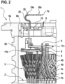
- Figure 2 shows a schematic sectional view through the electrical machine 1.
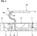
- Figure 3 shows a detailed view of this section view.
- the electrical winding 3 of the stator 2 has a total of three phase strands 4a, 4b, 4c.
- the stator 2 is thus designed as a three-phase system.
- Each connection element 7a, 7b, 7c is electrically connected to a respective connection element 8a, 8b, 8c, a first connection element 8a, a second connection element 8b and a third connection element 8c, wherein in Figure 2 Due to the sectional view, only the second connecting element 8b is visible.
- Each connecting element 8a, 8b, 8c is part of a conductor rail 17a, 17b, 17c, a first conductor rail 17a, a second conductor rail 17b and a third conductor rail 17c, wherein in Figure 2 only the second conductor rail 17b and the third conductor rail 17c are visible.
- the conductor rails 17a, 17b, 17c serve to electrically contact ends 6 of the individual phase strands 4a, 4b, 4c.
- the winding 3 is composed, in particular, of U-shaped or I-shaped conductor elements.
- the conductor rails 17a, 17b, 17c are designed for interconnecting these individual conductor elements.
- the connecting elements 8a, 8b, 8c are mechanically and electrically connected to the connecting elements 7a, 7b, 7c.
- the connecting elements 7a, 7b, 7c each have a contact section 18a, 18b, 18c for electrically contacting a phase of an external power supply.
- the external power supply is, for example, an inverter.
- the connecting elements 7a, 7b, 7c each have a flexible section 19a, 19b, 19c.
- the flexible section 19a, 19b, 19c is formed, for example, by a plurality of lamella strips 20.
- the connecting element 7a, 7b, 7c, in particular, the flexible section 19a, 19b, 19c is each designed to be elastic in order to achieve tolerance compensation and/or movement compensation between the stator 2 and the connecting element 7a, 7b, 7c, in particular the contact section 18a, 18b, 18c of the respective connecting element 7a, 7b, 7c.
- a support part 10 is arranged in the opening 9.
- the support part 10 serves to provide vibration-damping support for the connecting element 7a, 7b, 7c and/or the connecting element 8a, 8b, 8c.
- support occurs in the radial direction 200.
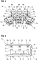
- Figure 4 shows a schematic detailed view of individual components of the electrical machine 1. These are in particular the connection elements 7a, 7b, 7c and the connecting elements 8a, 8b, 8c.
- the support part 10 is also shown.
- a holding structure 22 is shown schematically. The holding structure 22 is used to be plugged onto the ends 6 of the phase strands 4a, 4b, 4c of the winding 3. In addition, the ends 6 are plugged through the respective conductor rails 17a, 17b, 17c.
- the support part 10 is shown schematically in Figure 5
- the detailed view from Figure 3 shows schematically the interaction of support part 10 and connecting elements 7a, 7b, 7c as well as connecting elements 8a, 8b, 8c using the example of the second connecting element 7b and the second connecting element 8b.
- the support part 10 has a base body 16, wherein the base body 16 comprises a first leg 16a, a second leg 16b and a third leg 16c.
- the third leg 16c serves to connect the first leg 16a and the second Legs 16b, wherein the first leg 16a and the second leg 16b each have a free end.
- the base body 16 is essentially C-shaped.
- the C-shaped design of the base body and/or with the aforementioned legs 16a, 16b, 16c enables simple and reliable assembly of the support part 10 within the opening 9.
- the first leg 16a and the second leg 16b can be elastically deformed, in particular pressed apart, in order to insert the connecting elements 7a, 7b, 7c and/or connecting elements 8a, 8b, 8c into an area within the base body 16.
- the base body 16 at least partially encloses the connecting elements 7a, 7b, 7c and/or connecting elements 8a, 8b, 8c, in three directions in the embodiment shown.
- the first support contours 11 and second support contours 12 serve to support the connecting elements 7a, 7b, 7c and/or connecting elements 8a, 8b, 8c, wherein said elements are clamped between the first support contour 11 and the second support contour 12. It is provided that a separate pair of first support contour 11 and second support contour 12 is provided for each connecting element 7a, 7b, 7c and/or for each connecting element 8a, 8b, 8c. In the embodiment shown, three pairs of first pointed contour 11 and second pointed contour 12 are provided due to the presence of three connecting elements 7a, 7b, 7c and three connecting elements 8a, 8b, 8c.
- the first support contours 11 and second support contours 12 are preferably in multiple line contact with the respective connecting element 7a, 7b, 7c and/or connecting element 8a, 8b, 8c, in that the support contours have a wave-shaped and/or sawtooth-shaped surface.
- a defined contact between the support contour 11, 12 and the connecting element 7a, 7b, 7c and/or connecting element 8a, 8b, 8c is achieved.
- the first support contours 11 extend inwards from the first leg 16a, ie, into the area which is at least partially surrounded by the base body 16.
- the first leg 16a third support contours 13 outwards, i.e., opposite to the direction of the first support contours 11.
- the second support contours 12 extend inwards, with third support contours 13 also extending outwards on the second leg 16b, and thus opposite to the direction of extension of the second support contours 12. It is provided that an equal number of first support contours 11 and third support contours 13 extend from the first leg 16a.
- An equal number of second support contours 12 and third support contours 13 extend from the second leg 16b.
- no support contours extend inward from the third leg 16c.
- Fourth support contours 14 extend outward from the third leg 16c.
- the third support contours 13 and the fourth support contours 14 serve to support the base body 16 relative to the housing 9.
- the third support contours 13 and the fourth support contours 14 are designed to taper conically toward the housing 9 in order to establish linear contact with the housing 9.
- a defined support is also provided here.
- the support part 10 is thus optimally arranged within the opening 9 and allows the connection elements 7a, 7b, 7c and/or connecting elements 8a, 8b, 8c to be supported relative to the housing 5a, 5b.
- the support part 10 can preferably be inserted into the opening 9 of the housing 5a, 5b in the axial direction 100.
- the base body 16 advantageously has a plurality of axial stops 15, wherein the axial stops 15 define an end position of the support part 10 in the opening 9 of the housing 5a, 5b in the axial direction 100. This ensures simple and reliable assembly of the support
- the support part 10 is preferably designed to be electrically insulating. Thus, a short circuit of the individual phase strands 4a, 4b, 4c through the support part 10 is prevented.
- the support part 10 is made, for example, from a plastic material. Particularly advantageously, the support part 10 is an injection-molded part.
- the support part 10 also ensures a defined position of the connecting element 7a, 7b, 7c and the connecting element 8a, 8b, 8c relative to the housing 5a, 5b. This eliminates the need for any additional components for fixing the position of these elements relative to the housing 5a, 5b.
Landscapes
- Engineering & Computer Science (AREA)
- Power Engineering (AREA)
- Insulation, Fastening Of Motor, Generator Windings (AREA)
- Motor Or Generator Frames (AREA)
Abstract
Description
- Die vorliegende Erfindung betrifft eine elektrische Maschine. Die elektrische Maschine weist insbesondere Verbesserungen hinsichtlich der Schwingungsfestigkeit interner elektrischer Leiter auf.
- Aus dem Stand der Technik ist bekannt, dass elektrische Maschine eigene Anschlusselemente aufweisen, die zum elektrischen Kontaktieren mit einem Inverter vorgesehen sind. Die Anschlusselemente können beispielsweise fest an einem Gehäuse der elektrischen Maschine angebracht sein. Dies dient zum einfachen und zuverlässigen Befestigen und elektrischen Kontaktieren von Anschlüssen des Inverters. Die Anschlusselemente sind über Verbindungselemente mit einer Wicklung der elektrischen Maschine verbunden. Die Verbindungselemente oder Anschlusselemente weisen zumindest flexibel ausgebildete Teilabschnitte auf, die dafür vorgesehen sind, einen Toleranzausgleich zwischen Wicklung und Anschlusselement vorzunehmen.
- Die erfindungsgemäße elektrische Maschine weist eine verbesserte Schwingungsfestigkeit interner elektrischer Verbindungselemente auf. Insbesondere ist auf diese Weise die Gefahr von Schwingungsbrüchen von internen Verbindungselementen vermindert oder ausgeschlossen.
- Die elektrische Maschine weist einen Stator mit einer mehrphasigen elektrischen Wicklung auf. Die Wicklung wiederum weist zumindest einen Phasenstrang auf. Vorteilhafterweise weist die elektrische Wicklung drei Phasenstränge auf. Der Stator ist innerhalb eines Gehäuses der elektrischen Maschine angeordnet. Das Gehäuse weist eine Öffnung zur Durchführung einer elektrischen Verbindung auf. Außerdem ist zumindest ein elektrisch leitfähiges Anschlusselement vorgesehen. Das Anschlusselement ist ausgebildet zum Anschließen eines der Phasenstränge an die Phase einer externen Energieversorgung. Bei der externen Energieversorgung kann es sich insbesondere um einen Inverter handeln. Es ist somit vorteilhafterweise vorgesehen, dass ein Anschlusselement pro Phasenstrang der Wicklung vorgesehen ist. Besonders vorteilhaft sind alle Anschlusselemente an dem Gehäuse angebracht oder fixiert. Das zumindest eine Anschlusselement befindet sich vorteilhafterweise auf einer anderen Seite des Gehäuses als der Stator.
- Die elektrische Maschine weist weiterhin zumindest ein elektrisch leitfähiges Verbindungselement auf. Das Verbindungselement erstreckt sich zwischen einem Ende eines der Phasenstränge der Wicklung und dem Anschlusselement. Auf diese Weise verbindet das elektrisch leitfähige Verbindungselement den Phasenstrang mit dem Anschlusselement. Das Anschlusselement ist elastisch ausgebildet, um einen Toleranzausgleich und/oder Bewegungsausgleich zwischen dem Stator und dem Anschlusselement zu erreichen. Besonders vorteilhaft ist vorgesehen, dass für jeden Phasenstrang ein eigenes Anschlusselement sowie ein eigenes Verbindungselement vorgesehen ist. In dem o.g. beispielhaften Design mit drei Phasensträngen der elektrischen Wicklung sind somit drei Anschlusselemente und drei Verbindungselemente vorgesehen, wobei jeweils ein Phasenstrang über ein eigenes Verbindungselement mit einem separaten Anschlusselement elektrisch verbunden ist.
- In einer besonders vorteilhaften Ausgestaltung führt das elektrisch leitfähige Verbindungselement durch die Öffnung des Gehäuses. Dies ermöglicht ein Anordnen von Stator- und Anschlusselementen auf unterschiedlichen Seiten des Gehäuses. Insbesondere lässt sich der Stator so durch das Gehäuse vor äußeren Einflüssen abschirmen.
- Es ist weiterhin vorgesehen, dass das zumindest eine Anschlusselement und/oder das Verbindungselement mittels eines in der Öffnung des Gehäuses angeordneten Abstützteils schwingungsdämpfend abgestützt ist. Die Schwingungsdämpfung erfolgt vorteilhafterweise durch eine Erhöhung der Eigenfrequenz des Verbindungselements und/oder des Anschlusselements aufgrund des Abstützens an dem Gehäuse durch das Abstützteil. Alternativ oder zusätzlich wird durch das Abstützteil ein Schwingungsweg des Anschlusselements und/oder des Verbindungselements durch mechanisches Fixieren verringert. Die genannten Maßnahmen tragen dazu bei, die Schwingungsbeanspruchbarkeit des Anschlusselementes und/oder des Verbindungselements zu erhöhen. Die Gefahr von Schwingungsbrüchen des Anschlusselements und/oder des Verbindungselements ist dadurch reduziert oder vermieden.
- Die Unteransprüche zeigen bevorzugte Weiterbildungen der Erfindung.
- Bevorzugt weist das Abstützteil zumindest eine erste Stützkontur zum Abstützen des Anschlusselements und/oder des Verbindungselements auf. Die erste Stützkontur liegt an dem Anschlusselement und/oder Verbindungselement an und sorgt somit für besagte schwingungsdämpfende Abstützung. Vorteilhafterweise ist jeweils eine erste Stützkontur für jeweils ein Anschlusselement und/oder Verbindungselement vorgesehen. Die erste Stützkontur kann beispielsweise als Vorsprung oder als hervorstehender Arm ausgebildet sein.
- Besonders bevorzugt weist das Abstützteil zumindest eine zweite Stützkontur auf. Die zweite Stützkontur ist zur Abstützung des Anschlusselements und/oder Verbindungselements ausgebildet. Die zweite Stützkontur ist gegenüberliegend der ersten Stützkontur ausgebildet. Das Anschlusselement und/oder das Verbindungselement sind vorteilhafterweise zwischen der ersten Stützkontur und der zweiten Stützkontur angeordnet. Besonders bevorzugt ist vorgesehen, dass das Anschlusselement und/oder das Verbindungselement zwischen der ersten Stützkontur und der zweiten Stützkontur eingeklemmt sind. Die zweite Stützkontur ist vorteilhafterweise analog zu der ersten Stützkontur ausgebildet. Somit ist die zweite Stützkontur vorteilhafterweise als Vorsprung und/oder als hervorstehender Arm ausgebildet. Die zweite Stützkontur und die erste Stützkontur können somit ein Verbindungselement und/oder Anschlusselement von zwei Seiten abstützen. Dies ist insbesondere vorteilhaft, wenn das Anschlusselement und/oder Verbindungselement als Flachleiter ausgebildet sind. Eine solche Ausbildung von Anschlusselement und/oder Verbindungselement ist eine vorteilhafte Ausführung der elektrischen Maschine.
- Die erste Stützkontur und/oder die zweite Stützkontur weisen bevorzugt einen einfachen oder mehrfachen linienförmigen Kontakt zu dem jeweiligen Anschlusselement oder Verbindungselement auf. Dies ist insbesondere dadurch erreicht, dass die erste Stützkontur und/oder die zweite Stützkontur eine Wellenform und/oder eine Sägezahnform aufweisen, um mit dieser Form in Kontakt mit der jeweiligen Oberfläche von Anschlusselement und/oder Verbindungselement zu gelangen. Auf diese Weise ist insbesondere eine vollflächige Anlage der Stützkontur oder der Stützkonturen vermieden. Dadurch ist eine definierte Auflage des Abstützteils an dem Anschlusselement und/oder dem Verbindungselement erreicht.
- Besonders vorteilhaft weist das Abstützteil eine dritte Stützkontur auf. Die dritte Stützkontur erstreckt sich nach außen und liegt an dem Gehäuse an. Unter einem Erstrecken nach außen ist insbesondere zu verstehen, dass sich die dritte Stützkontur von dem Anschlusselement und/oder von dem Verbindungselement weg erstreckt. Somit erfolgt ein Abstützen des Abstützteils gegenüber dem Gehäuse, wobei die Schwingungsdämpfung von Anschluss und/oder Verbindungselement dadurch optimiert ist.
- Besonders vorteilhaft weist die dritte Stützkontur einen Linienkontakt zu dem Gehäuse auf. Der Linienkontakt kann einfach oder mehrfach ausgebildet sein. Wie zuvor beschrieben, ist besonders vorteilhaft eine Wellenform und/oder eine Sägezahnform vorgesehen, um den Kontakt zwischen der dritten Stützkontur und dem Gehäuse zu erreichen. Dies führt wiederum zu einer vorteilhaften definierten der dritten Stützkontur an dem Gehäuse.
- Vorteilhafterweise weist das Abstützteil einen Grundkörper auf. Der Grundkörper ist insbesondere ringförmig oder C-förmig ausgebildet. Mit einer C-Form ist insbesondere eine offene Ringform gemeint, wobei die C-Form durch einen abgerundeten Körper und/oder durch mehrere zueinander abgewinkelte Segmente eines Körpers erreicht werden kann. Der Grundkörper umgibt das Anschlusselement und/oder das Verbindungselement zumindest teilweise. Es ist vorteilhafterweise vorgesehen, dass der Grundkörper einen ersten Schenkel, einen zweiten Schenkel und einen den ersten Schenkel und den zweiten Schenkel verbindenden dritten Schenkel aufweist. Der erste Schenkel und der zweite Schenkel weisen bevorzugt ein freies Ende auf, wobei diese Form vorteilhafterweise ein elastisches Aufbiegen von erstem Schenkel und zweitem Schenkel ermöglicht. Dadurch ist das Montieren des Abstützteils und/oder des Verbindungselements und/oder des Anschlusselements vereinfacht.
- An dem ersten Schenkel ist bevorzugt die zumindest eine erste Stützkontur angebracht. An dem zweiten Schenkel ist bevorzugt die zuvor genannte zumindest eine zweite Stützkontur angebracht. Es ist vorteilhafterweise vorgesehen, dass an dem ersten Schenkel gleich viele erste Stützkonturen und dritte Stützkonturen angeordnet sind. Alternativ oder zusätzlich ist bevorzugt vorgesehen, dass an dem zweiten Schenkel gleich viele zweite Stützkonturen und dritte Stützkonturen angeordnet sind. Die dritten Stützkonturen erstrecken sich von dem ersten Schenkel bevorzugt in entgegengesetzte Richtungen wie die ersten Stützkonturen. Von dem zweiten Schenkel erstrecken sich die dritten Stützkonturen bevorzugt in entgegengesetzte Richtung wie die zweiten Stützkonturen. Auf diese Weise erfolgt eine zuverlässige Abstützung des zumindest einen Verbindungselements und/oder des zumindest einen Anschlusselements an dem Gehäuse, indem der Kraftfluss der Abstützung von der ersten Stützkontur über den ersten Schenkel und die dritte Stützkontur in das Gehäuse geleitet wird. In analoger Weise wird besagter Kraftfluss über die zweite Stützkontur und den zweiten Schenkel sowie einer weiteren dritten Stützkontur in das Gehäuse geleitet. Damit sind Schwingungen des Anschlusselements und/oder des Verbindungselements zuverlässig reduziert.
- In einer vorteilhaften Ausgestaltung weist das Abstützteil zumindest eine vierte Stützkontur auf. Die vierte Stützkontur erstreckt sich von dem dritten Schenkel nach außen. Vorteilhafterweise liegt die vierte Stützkontur an dem Gehäuse an, besonders vorteilhaft über einen einfachen oder mehrfachen Linienkontakt. Der einfache oder mehrfache Linienkontakt wird insbesondere über eine Sägezahnform und/oder Wellenform der vierten Stützkontur erreicht. Besonders vorteilhaft erstrecken sich von dem dritten Schenkel keinerlei Stützkonturen nach innen, d.h., keinerlei Stützkonturen zu dem Anschlusselement und/oder Verbindungselement. Somit dient der dritte Schenkel, von dem sich die zumindest eine vierte Stützkontur erstreckt, lediglich der Verbindung des ersten Schenkels und zweiten Schenkels sowie dem Anordnen des Abstützteils innerhalb der Öffnung des Gehäuses.
- Das Abstützteil ist vorteilhafterweise entlang einer Axialrichtung der elektrischen Maschine in die Öffnung des Gehäuses einsetzbar. Die Axialrichtung der elektrischen Maschine ist insbesondere die Axialrichtung des Rotors und/oder Stators der elektrischen Maschine. Die Axialrichtung verläuft insbesondere parallel zu einer Mittelachse von Rotor und/oder Stator der elektrischen Maschine. Das Abstützteil weist mindestens einen Axialanschlag auf, durch den in Axialrichtung eine Endposition des Abstützteils in dem Gehäuse definiert ist. Eine Montage des Abstützteils ist somit einfach und aufwandsarm möglich. Auch ist das Abstützteil zuverlässig innerhalb der Öffnung angeordnet.
- Das Verbindungselement ist vorteilhafterweise Teil einer Leiterschiene. Die Leiterschiene verschaltet Leiterstränge der Wicklung 3 miteinander. Die Wicklung 3 ist vorteilhafterweise durch U-förmige und/oder I-förmige Leiterstücke gebildet, deren Enden durch die Leiterschiene zu der Wicklung miteinander verschaltet sind. Besonders vorteilhaft ist durch jeweils eine Leiterschiene ein Phasenstrang der Wicklung verschaltet. Somit ist bei Vorhandensein mehrerer Verbindungselemente jedes Verbindungselement Teil einer eigenen Leiterschiene.
- Das Abstützteil ist vorteilhafterweise elektrisch isolierend ausgebildet. Besonders vorteilhaft ist das Abstützteil aus einem elektrisch isolierenden Material gefertigt. Auf diese Weise ist ein Kurzschluss der einzelnen Phasenstränge der Wicklung durch das Abstützteil ausgeschlossen.
- Das Anschlusselement weist bevorzugt einen Kontaktabschnitt zur elektrischen Kontaktierung der Phase der externen Energieversorgung und einen Flexabschnitt zur elastischen Verbindung mit dem Verbindungselement auf. Der Flexabschnitt weist im Querschnitt bevorzugt eine Vielzahl von Litzen oder eine Vielzahl von Lamellenbändern auf. Der Kontaktabschnitt weist im Querschnitt insbesondere ein einzelnes Leiterband oder eine Vielzahl von Lamellenbändern auf. Durch derartige Ausgestaltungen ist insbesondere erreicht, dass der Flexabschnitt eine Flexibilität erlaubt. Der Kontaktabschnitt hingegen ist robust und erlaubt eine zuverlässige Kontaktierung externer Komponenten.
- Nachfolgend werden Ausführungsbeispiele der Erfindung unter Bezugnahme auf die begleitenden Zeichnungen im Detail beschrieben. In der Zeichnung ist:
- Figur 1
- eine schematische Ansicht einer elektrischen Maschine gemäß einem Ausführungsbeispiel der Erfindung,
- Figur 2
- eine schematische Schnittansicht durch die elektrische Maschine gemäß dem Ausführungsbeispiel der Erfindung,
- Figur 3
- eine schematische Detailansicht der Schnittansicht durch die elektrische Maschine gemäß dem Ausführungsbeispiel der Erfindung,
- Figur 4
- eine schematische Detailansicht einzelner Komponenten der elektrischen Maschine gemäß dem Ausführungsbeispiel der Erfindung, und
- Figur 5
- eine schematische Detailansicht eines Abstützteils der elektrischen Maschine.
- Bevorzugt sind alle gleichen Bauteile, Elemente und/oder Einheiten in allen Figuren mit den gleichen Bezugszeichen versehen.
-
Figur 1 zeigt schematisch eine elektrische Maschine 1 gemäß einem Ausführungsbeispiel der Erfindung. Die elektrische Maschine 1 weist einen Stator 2 mit einer elektrischen Wicklung 3 auf, wobei inFigur 1 lediglich schematisch Wickelköpfe der Wicklung 3 gezeigt sind. Durch den Stator 2 ist ein Rotor 21 antreibbar. - Der Stator 2 ist in einem Gehäuse 5a, 5b befestigt, wobei das Gehäuse 5a, 5b ein Topfelement 5b und ein das Topfelement 5b verschließendes Deckelelement 5a aufweist. In dem Deckelelement 5a ist eine Öffnung 9 zum Durchführen einer elektrischen Verbindung vorgesehen. Auf diese Weise ist ermöglicht, ein Anschlusselement 7 außerhalb des Gehäuses 5a, 5b vorzusehen, um die Wicklung 3 des Stators 2 innerhalb des Gehäuses 5a, 5b elektrisch zu kontaktieren. Ein Verbindungselement 8 verbindet das Anschlusselement 7 mit der Wicklung 3.
- Entlang einer Mittelachse des Stators 2 und/oder Rotors 21 ist eine Axialrichtung 100 definiert. Senkrecht dazu ist eine Radialrichtung 200 definiert. Die Öffnung 9 erstreckt sich beispielsweise in Axialrichtung 100 durch das Gehäuse 5a, 5b.
-
Figur 2 zeigt schematisch eine Schnittansicht durch die elektrische Maschine 1.Figur 3 zeigt eine Detailansicht dieser Schnittansicht. - Die elektrische Wicklung 3 des Stators 2 weist insgesamt drei Phasenstränge 4a, 4b, 4c auf. Der Stator 2 ist somit dreiphasig ausgebildet. Somit sind drei elektrisch leitfähige Anschlusselemente 7a, 7b, 7c vorhanden, ein erstes Anschlusselement 7a, ein zweites Anschlusselement 7b und ein drittes Anschlusselement 7c, wobei in der Schnittansicht gemäß
Figur 2 lediglich das zweite Anschlusselement 7b sichtbar ist. Jedes Anschlusselement 7a, 7b, 7c ist mit jeweils einem Verbindungselement 8a, 8b, 8c elektrisch verbunden, einem ersten Verbindungselement 8a, einem zweiten Verbindungselement 8b und einem dritten Verbindungselement 8c, wobei inFigur 2 aufgrund der Schnittansicht lediglich das zweite Verbindungselement 8b sichtbar ist. Jedes Verbindungselement 8a, 8b, 8c ist Teil einer Leiterschiene 17a, 17b, 17c, einer ersten Leiterschiene 17a, einer zweiten Leiterschiene 17b und einer dritten Leiterschiene 17c, wobei inFigur 2 lediglich die zweite Leiterschiene 17b und die dritte Leiterschiene 17c sichtbar sind. Die Leiterschienen 17a, 17b, 17c dienen dazu, Enden 6 der einzelnen Phasenstränge 4a, 4b, 4c elektrisch zu kontaktieren. Die Wicklung 3 ist insbesondere aus U-förmigen oder I-förmigen Leiterelementen zusammengesetzt. Die Leiterschienen 17a, 17b, 17c sind zum Verschalten dieser einzelnen Leiterelemente ausgebildet. - Die Verbindungselemente 8a, 8b, 8c sind mechanisch und elektrisch mit den Anschlusselementen 7a, 7b, 7c verbunden. Dabei weisen die Anschlusselemente 7a, 7b, 7c jeweils einen Kontaktabschnitt 18a, 18b, 18c zur elektrischen Kontaktierung einer Phase einer externen Energieversorgung auf. Bei der externen Energieversorgung handelt es sich beispielsweise um einen Inverter. Weiterhin weisen die Anschlusselemente 7a, 7b, 7c jeweils einen Flexabschnitt 19a, 19b, 19c auf. Der Flexabschnitt 19a, 19b, 19c ist beispielsweise durch eine Vielzahl von Lamellenbändern 20 gebildet. Das Anschlusselement 7a, 7b, 7c, insbesondere der Flexabschnitt 19a, 19b, 19c ist jeweils elastisch ausgebildet, um einen Toleranzausgleich und/oder einen Bewegungsausgleich zwischen dem Stator 2 und dem Anschlusselement 7a, 7b, 7c, insbesondere dem Kontaktabschnitt 18a, 18b, 18c des jeweiligen Anschlusselements 7a, 7b, 7c, zu erreichen.
- Um unerwünschte Schwingungen der Anschlusselemente 7a, 7b, 7c und/oder der Verbindungselemente 8a, 8b, 8c zu vermeiden, ist in der Öffnung 9 ein Abstützteil 10 angeordnet. Das Abstützteil 10 dient zum schwingungsdämpfenden Abstützen von Anschlusselement 7a, 7b, 7c und/oder Verbindungselement 8a, 8b, 8c. Beispielsweise erfolgt ein Abstützen in Radialrichtung 200. Auf diese Weise ist die Gefahr von Schwingungsbrüchen des Anschlusselements 7a, 7b, 7c und/oder des Verbindungselements 8a, 8b, 8c, besonders vorteilhaft des Flexabschnitts 19a, 19b, 19c des jeweiligen Anschlusselementes 7a, 7b, 7c, minimiert.
-
Figur 4 zeigt schematisch eine Detailansicht einzelner Komponenten der elektrischen Maschine 1. Dabei handelt es sich insbesondere um die Anschlusselemente 7a, 7b, 7c sowie um die Verbindungselemente 8a, 8b, 8c. Außerdem ist das Abstützteil 10 gezeigt. Darüber hinaus ist schematisch eine Haltestruktur 22 dargestellt. Die Haltestruktur 22 dient zum Aufstecken auf die Enden 6 der Phasenstränge 4a, 4b, 4c der Wicklung 3. Zusätzlich werden die Enden 6 durch die jeweiligen Leiterschienen 17a, 17b, 17c gesteckt. Dies führt einerseits zum Verschalten der Wicklung 3, andererseits zum elektrischen Kontaktieren der Verbindungselemente 8a, 8b, 8c, die Teil der Leiterschienen 17a, 17b, 17c sind, mit den Phasensträngen 4a, 4b, 4c. - Das Abstützteil 10 ist schematisch in
Figur 5 dargestellt. Die Detailansicht ausFigur 3 zeigt schematisch das Zusammenwirken von Abstützteil 10 und Anschlusselementen 7a, 7b, 7c sowie Verbindungselementen 8a, 8b, 8c am Beispiel des zweiten Anschlusselements 7b und des zweiten Verbindungselements 8b. - Das Abstützteil 10 weist in dem gezeigten Ausführungsbeispiel einen Grundkörper 16 auf, wobei der Grundkörper 16 einen ersten Schenkel 16a, einen zweiten Schenkel 16b und einen dritten Schenkel 16c umfasst. Der dritte Schenkel 16c dient zum Verbinden von erstem Schenkel 16a und zweitem Schenkel 16b, wobei der erste Schenkel 16a und der zweite Schenkel 16b jeweils ein freies Ende aufweisen. Dadurch ist der Grundkörper 16 im Wesentlichen C-förmig ausgebildet.
- Die Ausbildung des Grundkörpers in C-Form und/oder mit den genannten Schenkeln 16a, 16b, 16c ermöglicht eine einfache und zuverlässige Montage des Abstützteils 10 innerhalb der Öffnung 9. Der erste Schenkel 16a und der zweite Schenkel 16b lassen sich elastisch verformen, insbesondere auseinanderdrücken, um die Anschlusselemente 7a, 7b, 7c und/oder Verbindungselemente 8a, 8b, 8c in einen Bereich innerhalb des Grundkörpers 16 einzuführen. Mit anderen Worten umschließt der Grundkörper 16 die Anschlusselemente 7a, 7b, 7c und/oder Verbindungselemente 8a, 8b, 8c zumindest teilweise, in dem gezeigten Ausführungsbeispiel in drei Richtungen.
- Von dem Grundkörper 16 erstrecken sich erste Stützkonturen 11, zweite Stützkonturen 12 und dritte Stützkonturen 13, sowie vierte Stützkonturen 14. Die ersten Stützkonturen 11 und zweiten Stützkonturen 12 dienen zum Abstützen der Anschlusselemente 7a, 7b, 7c und/oder Verbindungselemente 8a, 8b, 8c, wobei besagte Elemente zwischen der ersten Stützkontur 11 und der zweiten Stützkontur 12 eingeklemmt sind. Es ist vorgesehen, dass für jedes Anschlusselement 7a, 7b, 7c und/oder für jedes Verbindungselement 8a, 8b, 8c ein eigenes Paar von erster Stützkontur 11 und zweiter Stützkontur 12 vorgesehen ist. In dem gezeigten Ausführungsbeispiel sind somit aufgrund des Vorhandenseins von drei Anschlusselementen 7a, 7b, 7c sowie drei Verbindungselementen 8a, 8b, 8c drei Paare von erster Spitzkontur 11 und zweiter Spitzkontur 12 vorgesehen.
- Die ersten Stützkonturen 11 und zweiten Stützkonturen 12 stehen mit dem jeweiligen Anschlusselement 7a, 7b, 7c und/oder Verbindungselement 8a, 8b, 8c bevorzugt in mehrfachem Linienkontakt, indem die Abstützkonturen eine wellenförmige und/oder sägezahnförmige Oberfläche aufweisen. Somit ist ein definierter Kontakt zwischen Abstützkontur 11, 12 und Anschlusselement 7a, 7b, 7c und/oder Verbindungselement 8a, 8b, 8c erreicht.
- Die ersten Abstützkonturen 11 erstrecken sich von dem ersten Schenkel 16a nach innen, d.h., in den Bereich der von dem Grundkörper 16 zumindest teilweise umgeben ist. Außerdem erstrecken sich von dem ersten Schenkel 16a dritte Stützkonturen 13 nach außen, d.h., entgegengesetzt der Richtung der ersten Stützkonturen 11. An dem zweiten Schenkel 16b erstrecken sich die zweiten Stützkonturen 12 nach innen, wobei sich auch an den zweiten Schenkel 16b dritte Stützkonturen 13 nach außen erstrecken, und somit entgegen der Erstreckungsrichtung der zweiten Stützkonturen 12. Es ist vorgesehen, dass sich von dem ersten Schenkel 16a gleich viele erste Stützkonturen 11 und dritte Stützkonturen 13 erstrecken. Von dem zweiten Schenkel 16b erstrecken sich gleich viele zweite Stützkonturen 12 und dritte Stützkonturen 13.
- Von dem dritten Schenkel 16c erstrecken sich vorteilhafterweise keine Stützkonturen nach innen. Es ist vorgesehen, dass sich von dem dritten Schenkel 16c vierte Stützkonturen 14 nach außen erstrecken. Die dritten Stützkonturen 13 und die vierten Stützkonturen 14 dienen den Abstützen des Grundkörpers 16 gegenüber dem Gehäuse 9. Es ist vorgesehen, dass die dritten Stützkonturen 13 und vierten Stützkonturen 14 in Richtung des Gehäuses 9 konisch zulaufend ausgebildet sind, um einen Linienkontakt zu dem Gehäuse 9 herzustellen. Somit ist auch hier eine definierte Auflage vorhanden. Das Abstützteil 10 ist damit optimal innerhalb der Öffnung 9 angeordnet und erlaubt ein Abstützen der Anschlusselemente 7a, 7b, 7c und/oder Verbindungselemente 8a, 8b, 8c gegenüber dem Gehäuse 5a, 5b. Das Abstützteil 10 ist bevorzugt in Axialrichtung 100 in die Öffnung 9 des Gehäuses 5a, 5b einsetzbar. Der Grundkörper 16 weist vorteilhafterweise mehrere Axialanschläge 15 auf, wobei durch die Axialanschläge 15 eine Endposition des Abstützteils 10 in der Öffnung 9 des Gehäuses 5a, 5b in Axialrichtung 100 definiert ist. Somit ist eine einfache und zuverlässige Montage des Abstützteils 10 erreicht.
- Das Abstützteil 10 ist bevorzugt elektrisch isolierend ausgebildet. Somit ist ein Kurzschluss der einzelnen Phasenstränge 4a, 4b, 4c durch das Abstützteil 10 ausgeschlossen.
- Das Abstützteil 10 ist beispielsweise aus einem Kunststoff hergestellt. Besonders vorteilhaft ist das Abstützteil 10 ein Spritzgussteil. Durch das Abstützteil 10 ist außerdem eine definierte Lage von Anschlusselement 7a, 7b, 7c und Verbindungselement 8a, 8b, 8c relativ zum Gehäuse 5a, 5b sichergestellt. Somit können eventuelle Zusatzbauteile zur Fixierung der Lage dieser Elemente relativ zum Gehäuse 5a, 5b entfallen.
Claims (13)
- Elektrische Maschine (1) aufweisend- einen Stator (2) mit einer mehrphasigen elektrischen Wicklung (3), die zumindest einen Phasenstrang (4a, 4b, 4c) aufweist,- ein Gehäuse (5a, 5b), das eine Öffnung (9) zur Durchführung einer elektrischen Verbindung aufweist,- zumindest ein elektrisch leitfähiges Anschlusselement (7a, 7b, 7c) ausgebildet zum Anschließen eines der Phasenstränge (4a, 4b, 4c) an eine Phase einer externen Energieversorgung, insbesondere eines Inverters, und- zumindest ein elektrisch leitfähiges Verbindungselement (8a, 8b, 8c), das sich zwischen einem Ende (6) eines der Phasenstränge (4a, 4b, 4c) der Wicklung (3) und dem Anschlusselement (7a, 7b, 7c) erstreckt und den Phasenstrang (4a, 4b, 4c) mit dem Anschlusselement (7a, 7b, 7c) elektrisch verbindet,- wobei das Anschlusselement (7a, 7b, 7c) elastisch ausgebildet ist, um einen Toleranzausgleich und/oder Bewegungsausgleich zwischen dem Stator (2) und dem Anschlusselement (7a, 7b, 7c) zu erreichen,dadurch gekennzeichnet, dass das zumindest eine Anschlusselement (7a, 7b, 7c) und/oder das Verbindungselement (8a, 8b, 8c) mittels eines in der Öffnung (9) des Gehäuses (5a, 5b) angeordneten Abstützteils (10) schwingungsdämpfend abgestützt ist.
- Elektrische Maschine (1) nach Anspruch 1, dadurch gekennzeichnet, dass das Abstützteil (10) zumindest eine erste Stützkontur (11) zur Abstützung des Anschlusselementes (7a, 7b, 7c) und/oder Verbindungselementes (8a, 8b, 8c) aufweist.
- Elektrische Maschine (1) nach Anspruch 2, dadurch gekennzeichnet, dass das Abstützteil (10) zumindest eine zweite Stützkontur (12) zur Abstützung des Anschlusselementes (7a, 7b, 7c) und/oder Verbindungselementes aufweist, die gegenüberliegend der ersten Stützkontur (11) ausgebildet ist, wobei das Anschlusselement (7a, 7b, 7c) und/oder das Verbindungselement (8a, 8b, 8c)) zwischen der ersten Stützkontur (11) und der zweiten Stützkontur (12) angeordnet, insbesondere eingeklemmt, ist.
- Elektrische Maschine (1) nach Anspruch 2 oder 3, dadurch gekennzeichnet, dass die erste Stützkontur (11) und/oder die zweite Stützkontur (12), insbesondere mittels einer Wellenform und/oder einer Sägezahnform, einen einfachen oder mehrfachen linienförmigen Kontakt zum Anschlusselement (7a, 7b, 7c) und/oder Verbindungselement (8a, 8b, 8c) aufweisen.
- Elektrische Maschine (1) nach einem der Ansprüche 2 bis 4, dadurch gekennzeichnet, dass das Abstützteil (10) zumindest eine dritte Stützkontur (13) aufweist, die sich nach Außen erstreckt und an dem Gehäuse (5a, 5b) anliegt.
- Elektrische Maschine (1) nach Anspruch 5, dadurch gekennzeichnet, dass jede dritte Stützkontur (11) einen Linienkontakt zu dem Gehäuse (5a, 5b) aufweist.
- Elektrische Maschine (1) nach einem der vorhergehenden Ansprüche, dadurch gekennzeichnet, dass das Abstützteil (10) einen, insbesondere ringförmigen oder C-förmigen, Grundkörper (16) aufweist, der das Anschlusselement (7a, 7b, 7c) und/oder das Verbindungselement (8a, 8b, 8c) zumindest teilweise umgibt und insbesondere einen ersten Schenkel (16a), einen zweiten Schenkel (16b) und einen den ersten Schenkel (16a) und zweiten Schenkel (16b) verbindenden dritten Schenkel (16c) aufweist.
- Elektrische Maschine (1) nach Anspruch 7, dadurch gekennzeichnet, dass an dem ersten Schenkel (16a) gleich viele erste Stützkontur (11) und dritte Stützkontur (13) angeordnet sind und/oder dass an dem zweiten Schenkel (16b) gleich viele zweite Stützkontur (12) und dritte Stützkontur (13) angeordnet sind.
- Elektrische Maschine (1) nach Anspruch 7 oder 8, dadurch gekennzeichnet, dass das Abstützteil (10) zumindest eine vierte Stützkontur (14) aufweist, die sich von dem dritten Schenkel (16c) nach Außen erstreckt und, insbesondere über einen Linienkontakt, an dem Gehäuse (5a, 5b) anliegt.
- Elektrische Maschine (1) nach einem der vorhergehenden Ansprüche, dadurch gekennzeichnet, dass das Abstützteil (10) entlang einer Axialrichtung (100) der elektrischen Maschine (1) in die Öffnung (9) des Gehäuses (5a, 5b) einsetzbar ist und mindestens einen Axialanschlag (15) aufweist, durch den in Axialrichtung (100) eine Endposition des Abstützteils (10) in dem Gehäuse (5a, 5b) definiert ist.
- Elektrische Maschine (1) nach einem der vorhergehenden Ansprüche, dadurch gekennzeichnet, dass das Verbindungselement (8a, 8b, 8c) Teil einer Leiterschiene (17a, 17b, 17c) ist, die Leiterstränge der Wicklung (3) miteinander verschaltet.
- Elektrische Maschine (1) nach einem der vorhergehenden Ansprüche, dadurch gekennzeichnet, dass das Abstützteil (10) elektrisch isolierend ausgebildet, insbesondere aus einem elektrisch isolierendem Material gefertigt, ist.
- Elektrische Maschine (1) nach einem der vorhergehenden Ansprüche, dadurch gekennzeichnet, dass das Anschlusselement (7a, 7b, 7c) einen Kontaktabschnitt (18a, 18b, 18c) zur elektrischen Kontaktierung der Phase der externen Energieversorgung und einen Flexabschnitt (19a, 19b, 19c) zur elastischen Verbindung mit dem Verbindungselement (8a, 8b, 8c) aufweist, wobei der Flexabschnitt (19a, 19b, 19c) im Querschnitt insbesondere eine Vielzahl von Litzen oder eine Vielzahl von Lamellenbändern (20) umfasst, wobei der Kontaktabschnitt (18a, 18b, 18c) im Querschnitt insbesondere ein einzelnes Leiterband oder eine Vielzahl von Lamellenbändern (20) umfasst.
Applications Claiming Priority (1)
| Application Number | Priority Date | Filing Date | Title |
|---|---|---|---|
| DE102023211297.3A DE102023211297A1 (de) | 2023-11-14 | 2023-11-14 | Elektrische Maschine |
Publications (1)
| Publication Number | Publication Date |
|---|---|
| EP4557583A1 true EP4557583A1 (de) | 2025-05-21 |
Family
ID=93335238
Family Applications (1)
| Application Number | Title | Priority Date | Filing Date |
|---|---|---|---|
| EP24209739.2A Withdrawn EP4557583A1 (de) | 2023-11-14 | 2024-10-30 | Elektrische maschine mit anschlüssen |
Country Status (2)
| Country | Link |
|---|---|
| EP (1) | EP4557583A1 (de) |
| DE (1) | DE102023211297A1 (de) |
Citations (4)
| Publication number | Priority date | Publication date | Assignee | Title |
|---|---|---|---|---|
| US20170126092A1 (en) * | 2015-11-03 | 2017-05-04 | Lg Innotek Co., Ltd. | Motor |
| DE102019207647A1 (de) * | 2019-05-24 | 2020-11-26 | Zf Friedrichshafen Ag | Klemmvorrichtung und elektrische Maschine mit Klemmvorrichtung |
| DE102022101642A1 (de) * | 2021-02-25 | 2022-08-25 | Shinano Kenshi Co., Ltd. | Motorvorrichtung |
| US20230126488A1 (en) * | 2020-03-25 | 2023-04-27 | Nidec Corporation | Motor |
-
2023
- 2023-11-14 DE DE102023211297.3A patent/DE102023211297A1/de active Pending
-
2024
- 2024-10-30 EP EP24209739.2A patent/EP4557583A1/de not_active Withdrawn
Patent Citations (4)
| Publication number | Priority date | Publication date | Assignee | Title |
|---|---|---|---|---|
| US20170126092A1 (en) * | 2015-11-03 | 2017-05-04 | Lg Innotek Co., Ltd. | Motor |
| DE102019207647A1 (de) * | 2019-05-24 | 2020-11-26 | Zf Friedrichshafen Ag | Klemmvorrichtung und elektrische Maschine mit Klemmvorrichtung |
| US20230126488A1 (en) * | 2020-03-25 | 2023-04-27 | Nidec Corporation | Motor |
| DE102022101642A1 (de) * | 2021-02-25 | 2022-08-25 | Shinano Kenshi Co., Ltd. | Motorvorrichtung |
Also Published As
| Publication number | Publication date |
|---|---|
| DE102023211297A1 (de) | 2025-05-15 |
Similar Documents
| Publication | Publication Date | Title |
|---|---|---|
| DE102015200095B4 (de) | Stator für eine elektrische Maschine und Verfahren zum Herstellen eines solchen | |
| EP2082472B1 (de) | Elektromotor | |
| DE102015200089B4 (de) | Stator für eine elektrische Maschine und Verfahren zum Herstellen eines solchen | |
| EP2815486B1 (de) | Statoranordnung und elektrische maschine | |
| EP3320600A1 (de) | Statoranorndung, elektrische drehstrommaschine und verfahren zum herstellen einer statoranordnung | |
| WO2008135507A2 (de) | Stator mit stromschienen zum verschalten der spulen und entsprechendes verfahren | |
| WO2022156842A1 (de) | Hochvoltterminal | |
| EP3787120B1 (de) | Kontakteinsatz einer leiteranschlussklemme und leiteranschlussklemme | |
| WO2016110423A1 (de) | Verschaltungsplatte für einen stator einer elektrischen maschine und verfahren zum herstellen einer solchen | |
| EP3852246A1 (de) | Kontakteinrichtung eines stators, stator und elektrische maschine | |
| DE102018118280A1 (de) | Kontaktschnittstelle für einen Stator eines Elektromotors | |
| EP3824528A1 (de) | Elektromotor mit einer verschaltungseinheit und verfahren zur herstellung eines elektromotors mit einer verschaltungseinheit | |
| DE102021103787B3 (de) | Elektromotor mit Sammelschienen | |
| DE102018214104A1 (de) | Elektromaschine und Montageverfahren | |
| WO2022033630A1 (de) | ELEKTRISCHE MASCHINE MIT SCHUTZMECHANISMUS AN EINER SCHWEIßVERBINDUNG; SOWIE VERFAHREN ZUR MONTAGE DER ELEKTRISCHEN MASCHINE | |
| EP0996957B1 (de) | Kondensatoranschluss, insbesondere für einen elektrolyt-leistungskondensator | |
| EP4557583A1 (de) | Elektrische maschine mit anschlüssen | |
| EP3963692B1 (de) | Stator einer elektrischen maschine | |
| DE102020110651B4 (de) | Elektrische Kontaktierung eines Stators einer elektrischen Maschine | |
| DE102021207213A1 (de) | Elektrische Maschine | |
| EP3824530B1 (de) | Elektromotor mit einer verschaltungseinheit | |
| EP3824529A1 (de) | Elektromotor mit einer verschaltungseinheit und verfahren zur herstellung eines elektromotors mit einer verschaltungseinheit | |
| DE102011075575A1 (de) | Stator für eine Elektromaschine mit gekröpften Schweißfahnen zum Anschluss von Spulen | |
| DE102020133276A1 (de) | Anschlussbaugruppe für eine elektrische Maschine, sowie Verfahren zur Herstellung einer Anschlussbaugruppe | |
| WO2000057518A1 (de) | Hochstromverbinder zur kontaktierung elektrischer oder elektronischer baugruppen |
Legal Events
| Date | Code | Title | Description |
|---|---|---|---|
| PUAI | Public reference made under article 153(3) epc to a published international application that has entered the european phase |
Free format text: ORIGINAL CODE: 0009012 |
|
| STAA | Information on the status of an ep patent application or granted ep patent |
Free format text: STATUS: THE APPLICATION HAS BEEN PUBLISHED |
|
| AK | Designated contracting states |
Kind code of ref document: A1 Designated state(s): AL AT BE BG CH CY CZ DE DK EE ES FI FR GB GR HR HU IE IS IT LI LT LU LV MC ME MK MT NL NO PL PT RO RS SE SI SK SM TR |
|
| STAA | Information on the status of an ep patent application or granted ep patent |
Free format text: STATUS: REQUEST FOR EXAMINATION WAS MADE |
|
| 17P | Request for examination filed |
Effective date: 20251121 |
|
| STAA | Information on the status of an ep patent application or granted ep patent |
Free format text: STATUS: THE APPLICATION IS DEEMED TO BE WITHDRAWN |
|
| 18D | Application deemed to be withdrawn |
Effective date: 20251122 |