EP4557569A1 - Energy management device and energy management method - Google Patents
Energy management device and energy management method Download PDFInfo
- Publication number
- EP4557569A1 EP4557569A1 EP24849479.1A EP24849479A EP4557569A1 EP 4557569 A1 EP4557569 A1 EP 4557569A1 EP 24849479 A EP24849479 A EP 24849479A EP 4557569 A1 EP4557569 A1 EP 4557569A1
- Authority
- EP
- European Patent Office
- Prior art keywords
- ess
- operation schedule
- battery
- instruction
- energy management
- Prior art date
- Legal status (The legal status is an assumption and is not a legal conclusion. Google has not performed a legal analysis and makes no representation as to the accuracy of the status listed.)
- Pending
Links
Images


Classifications
-
- H—ELECTRICITY
- H02—GENERATION; CONVERSION OR DISTRIBUTION OF ELECTRIC POWER
- H02J—ELECTRIC POWER NETWORKS; CIRCUIT ARRANGEMENTS OR SYSTEMS FOR SUPPLYING OR DISTRIBUTING ELECTRIC POWER; SYSTEMS FOR STORING ELECTRIC ENERGY
- H02J7/00—Circuit arrangements for charging or discharging batteries or for supplying loads from batteries
- H02J7/90—Regulation of charging or discharging current or voltage
- H02J7/92—Regulation of charging or discharging current or voltage with prioritisation of loads or sources
-
- G—PHYSICS
- G06—COMPUTING OR CALCULATING; COUNTING
- G06Q—INFORMATION AND COMMUNICATION TECHNOLOGY [ICT] SPECIALLY ADAPTED FOR ADMINISTRATIVE, COMMERCIAL, FINANCIAL, MANAGERIAL OR SUPERVISORY PURPOSES; SYSTEMS OR METHODS SPECIALLY ADAPTED FOR ADMINISTRATIVE, COMMERCIAL, FINANCIAL, MANAGERIAL OR SUPERVISORY PURPOSES, NOT OTHERWISE PROVIDED FOR
- G06Q50/00—Information and communication technology [ICT] specially adapted for implementation of business processes of specific business sectors, e.g. utilities or tourism
- G06Q50/40—Business processes related to the transportation industry
-
- B—PERFORMING OPERATIONS; TRANSPORTING
- B60—VEHICLES IN GENERAL
- B60L—PROPULSION OF ELECTRICALLY-PROPELLED VEHICLES; SUPPLYING ELECTRIC POWER FOR AUXILIARY EQUIPMENT OF ELECTRICALLY-PROPELLED VEHICLES; ELECTRODYNAMIC BRAKE SYSTEMS FOR VEHICLES IN GENERAL; MAGNETIC SUSPENSION OR LEVITATION FOR VEHICLES; MONITORING OPERATING VARIABLES OF ELECTRICALLY-PROPELLED VEHICLES; ELECTRIC SAFETY DEVICES FOR ELECTRICALLY-PROPELLED VEHICLES
- B60L53/00—Methods of charging batteries, specially adapted for electric vehicles; Charging stations or on-board charging equipment therefor; Exchange of energy storage elements in electric vehicles
- B60L53/50—Charging stations characterised by energy-storage or power-generation means
- B60L53/51—Photovoltaic means
-
- B—PERFORMING OPERATIONS; TRANSPORTING
- B60—VEHICLES IN GENERAL
- B60L—PROPULSION OF ELECTRICALLY-PROPELLED VEHICLES; SUPPLYING ELECTRIC POWER FOR AUXILIARY EQUIPMENT OF ELECTRICALLY-PROPELLED VEHICLES; ELECTRODYNAMIC BRAKE SYSTEMS FOR VEHICLES IN GENERAL; MAGNETIC SUSPENSION OR LEVITATION FOR VEHICLES; MONITORING OPERATING VARIABLES OF ELECTRICALLY-PROPELLED VEHICLES; ELECTRIC SAFETY DEVICES FOR ELECTRICALLY-PROPELLED VEHICLES
- B60L53/00—Methods of charging batteries, specially adapted for electric vehicles; Charging stations or on-board charging equipment therefor; Exchange of energy storage elements in electric vehicles
- B60L53/50—Charging stations characterised by energy-storage or power-generation means
- B60L53/53—Batteries
-
- B—PERFORMING OPERATIONS; TRANSPORTING
- B60—VEHICLES IN GENERAL
- B60L—PROPULSION OF ELECTRICALLY-PROPELLED VEHICLES; SUPPLYING ELECTRIC POWER FOR AUXILIARY EQUIPMENT OF ELECTRICALLY-PROPELLED VEHICLES; ELECTRODYNAMIC BRAKE SYSTEMS FOR VEHICLES IN GENERAL; MAGNETIC SUSPENSION OR LEVITATION FOR VEHICLES; MONITORING OPERATING VARIABLES OF ELECTRICALLY-PROPELLED VEHICLES; ELECTRIC SAFETY DEVICES FOR ELECTRICALLY-PROPELLED VEHICLES
- B60L53/00—Methods of charging batteries, specially adapted for electric vehicles; Charging stations or on-board charging equipment therefor; Exchange of energy storage elements in electric vehicles
- B60L53/50—Charging stations characterised by energy-storage or power-generation means
- B60L53/57—Charging stations without connection to power networks
-
- B—PERFORMING OPERATIONS; TRANSPORTING
- B60—VEHICLES IN GENERAL
- B60L—PROPULSION OF ELECTRICALLY-PROPELLED VEHICLES; SUPPLYING ELECTRIC POWER FOR AUXILIARY EQUIPMENT OF ELECTRICALLY-PROPELLED VEHICLES; ELECTRODYNAMIC BRAKE SYSTEMS FOR VEHICLES IN GENERAL; MAGNETIC SUSPENSION OR LEVITATION FOR VEHICLES; MONITORING OPERATING VARIABLES OF ELECTRICALLY-PROPELLED VEHICLES; ELECTRIC SAFETY DEVICES FOR ELECTRICALLY-PROPELLED VEHICLES
- B60L53/00—Methods of charging batteries, specially adapted for electric vehicles; Charging stations or on-board charging equipment therefor; Exchange of energy storage elements in electric vehicles
- B60L53/60—Monitoring or controlling charging stations
- B60L53/62—Monitoring or controlling charging stations in response to charging parameters, e.g. current, voltage or electrical charge
-
- B—PERFORMING OPERATIONS; TRANSPORTING
- B60—VEHICLES IN GENERAL
- B60L—PROPULSION OF ELECTRICALLY-PROPELLED VEHICLES; SUPPLYING ELECTRIC POWER FOR AUXILIARY EQUIPMENT OF ELECTRICALLY-PROPELLED VEHICLES; ELECTRODYNAMIC BRAKE SYSTEMS FOR VEHICLES IN GENERAL; MAGNETIC SUSPENSION OR LEVITATION FOR VEHICLES; MONITORING OPERATING VARIABLES OF ELECTRICALLY-PROPELLED VEHICLES; ELECTRIC SAFETY DEVICES FOR ELECTRICALLY-PROPELLED VEHICLES
- B60L53/00—Methods of charging batteries, specially adapted for electric vehicles; Charging stations or on-board charging equipment therefor; Exchange of energy storage elements in electric vehicles
- B60L53/60—Monitoring or controlling charging stations
- B60L53/63—Monitoring or controlling charging stations in response to network capacity
-
- B—PERFORMING OPERATIONS; TRANSPORTING
- B60—VEHICLES IN GENERAL
- B60L—PROPULSION OF ELECTRICALLY-PROPELLED VEHICLES; SUPPLYING ELECTRIC POWER FOR AUXILIARY EQUIPMENT OF ELECTRICALLY-PROPELLED VEHICLES; ELECTRODYNAMIC BRAKE SYSTEMS FOR VEHICLES IN GENERAL; MAGNETIC SUSPENSION OR LEVITATION FOR VEHICLES; MONITORING OPERATING VARIABLES OF ELECTRICALLY-PROPELLED VEHICLES; ELECTRIC SAFETY DEVICES FOR ELECTRICALLY-PROPELLED VEHICLES
- B60L53/00—Methods of charging batteries, specially adapted for electric vehicles; Charging stations or on-board charging equipment therefor; Exchange of energy storage elements in electric vehicles
- B60L53/60—Monitoring or controlling charging stations
- B60L53/64—Optimising energy costs, e.g. responding to electricity rates
-
- B—PERFORMING OPERATIONS; TRANSPORTING
- B60—VEHICLES IN GENERAL
- B60L—PROPULSION OF ELECTRICALLY-PROPELLED VEHICLES; SUPPLYING ELECTRIC POWER FOR AUXILIARY EQUIPMENT OF ELECTRICALLY-PROPELLED VEHICLES; ELECTRODYNAMIC BRAKE SYSTEMS FOR VEHICLES IN GENERAL; MAGNETIC SUSPENSION OR LEVITATION FOR VEHICLES; MONITORING OPERATING VARIABLES OF ELECTRICALLY-PROPELLED VEHICLES; ELECTRIC SAFETY DEVICES FOR ELECTRICALLY-PROPELLED VEHICLES
- B60L53/00—Methods of charging batteries, specially adapted for electric vehicles; Charging stations or on-board charging equipment therefor; Exchange of energy storage elements in electric vehicles
- B60L53/60—Monitoring or controlling charging stations
- B60L53/66—Data transfer between charging stations and vehicles
- B60L53/665—Methods related to measuring, billing or payment
-
- B—PERFORMING OPERATIONS; TRANSPORTING
- B60—VEHICLES IN GENERAL
- B60L—PROPULSION OF ELECTRICALLY-PROPELLED VEHICLES; SUPPLYING ELECTRIC POWER FOR AUXILIARY EQUIPMENT OF ELECTRICALLY-PROPELLED VEHICLES; ELECTRODYNAMIC BRAKE SYSTEMS FOR VEHICLES IN GENERAL; MAGNETIC SUSPENSION OR LEVITATION FOR VEHICLES; MONITORING OPERATING VARIABLES OF ELECTRICALLY-PROPELLED VEHICLES; ELECTRIC SAFETY DEVICES FOR ELECTRICALLY-PROPELLED VEHICLES
- B60L55/00—Arrangements for supplying energy stored within a vehicle to a power network, i.e. vehicle-to-grid [V2G] arrangements
-
- B—PERFORMING OPERATIONS; TRANSPORTING
- B60—VEHICLES IN GENERAL
- B60L—PROPULSION OF ELECTRICALLY-PROPELLED VEHICLES; SUPPLYING ELECTRIC POWER FOR AUXILIARY EQUIPMENT OF ELECTRICALLY-PROPELLED VEHICLES; ELECTRODYNAMIC BRAKE SYSTEMS FOR VEHICLES IN GENERAL; MAGNETIC SUSPENSION OR LEVITATION FOR VEHICLES; MONITORING OPERATING VARIABLES OF ELECTRICALLY-PROPELLED VEHICLES; ELECTRIC SAFETY DEVICES FOR ELECTRICALLY-PROPELLED VEHICLES
- B60L58/00—Methods or circuit arrangements for monitoring or controlling batteries or fuel cells, specially adapted for electric vehicles
- B60L58/10—Methods or circuit arrangements for monitoring or controlling batteries or fuel cells, specially adapted for electric vehicles for monitoring or controlling batteries
- B60L58/12—Methods or circuit arrangements for monitoring or controlling batteries or fuel cells, specially adapted for electric vehicles for monitoring or controlling batteries responding to state of charge [SoC]
-
- B—PERFORMING OPERATIONS; TRANSPORTING
- B60—VEHICLES IN GENERAL
- B60L—PROPULSION OF ELECTRICALLY-PROPELLED VEHICLES; SUPPLYING ELECTRIC POWER FOR AUXILIARY EQUIPMENT OF ELECTRICALLY-PROPELLED VEHICLES; ELECTRODYNAMIC BRAKE SYSTEMS FOR VEHICLES IN GENERAL; MAGNETIC SUSPENSION OR LEVITATION FOR VEHICLES; MONITORING OPERATING VARIABLES OF ELECTRICALLY-PROPELLED VEHICLES; ELECTRIC SAFETY DEVICES FOR ELECTRICALLY-PROPELLED VEHICLES
- B60L58/00—Methods or circuit arrangements for monitoring or controlling batteries or fuel cells, specially adapted for electric vehicles
- B60L58/10—Methods or circuit arrangements for monitoring or controlling batteries or fuel cells, specially adapted for electric vehicles for monitoring or controlling batteries
- B60L58/18—Methods or circuit arrangements for monitoring or controlling batteries or fuel cells, specially adapted for electric vehicles for monitoring or controlling batteries of two or more battery modules
- B60L58/22—Balancing the charge of battery modules
-
- G—PHYSICS
- G06—COMPUTING OR CALCULATING; COUNTING
- G06Q—INFORMATION AND COMMUNICATION TECHNOLOGY [ICT] SPECIALLY ADAPTED FOR ADMINISTRATIVE, COMMERCIAL, FINANCIAL, MANAGERIAL OR SUPERVISORY PURPOSES; SYSTEMS OR METHODS SPECIALLY ADAPTED FOR ADMINISTRATIVE, COMMERCIAL, FINANCIAL, MANAGERIAL OR SUPERVISORY PURPOSES, NOT OTHERWISE PROVIDED FOR
- G06Q10/00—Administration; Management
- G06Q10/04—Forecasting or optimisation specially adapted for administrative or management purposes, e.g. linear programming or "cutting stock problem"
-
- G—PHYSICS
- G06—COMPUTING OR CALCULATING; COUNTING
- G06Q—INFORMATION AND COMMUNICATION TECHNOLOGY [ICT] SPECIALLY ADAPTED FOR ADMINISTRATIVE, COMMERCIAL, FINANCIAL, MANAGERIAL OR SUPERVISORY PURPOSES; SYSTEMS OR METHODS SPECIALLY ADAPTED FOR ADMINISTRATIVE, COMMERCIAL, FINANCIAL, MANAGERIAL OR SUPERVISORY PURPOSES, NOT OTHERWISE PROVIDED FOR
- G06Q10/00—Administration; Management
- G06Q10/06—Resources, workflows, human or project management; Enterprise or organisation planning; Enterprise or organisation modelling
- G06Q10/063—Operations research, analysis or management
-
- G—PHYSICS
- G06—COMPUTING OR CALCULATING; COUNTING
- G06Q—INFORMATION AND COMMUNICATION TECHNOLOGY [ICT] SPECIALLY ADAPTED FOR ADMINISTRATIVE, COMMERCIAL, FINANCIAL, MANAGERIAL OR SUPERVISORY PURPOSES; SYSTEMS OR METHODS SPECIALLY ADAPTED FOR ADMINISTRATIVE, COMMERCIAL, FINANCIAL, MANAGERIAL OR SUPERVISORY PURPOSES, NOT OTHERWISE PROVIDED FOR
- G06Q50/00—Information and communication technology [ICT] specially adapted for implementation of business processes of specific business sectors, e.g. utilities or tourism
- G06Q50/06—Energy or water supply
-
- H—ELECTRICITY
- H02—GENERATION; CONVERSION OR DISTRIBUTION OF ELECTRIC POWER
- H02J—ELECTRIC POWER NETWORKS; CIRCUIT ARRANGEMENTS OR SYSTEMS FOR SUPPLYING OR DISTRIBUTING ELECTRIC POWER; SYSTEMS FOR STORING ELECTRIC ENERGY
- H02J3/00—Circuit arrangements for AC mains or AC distribution networks
- H02J3/003—Load forecast, e.g. methods or systems for forecasting future load demand
-
- H—ELECTRICITY
- H02—GENERATION; CONVERSION OR DISTRIBUTION OF ELECTRIC POWER
- H02J—ELECTRIC POWER NETWORKS; CIRCUIT ARRANGEMENTS OR SYSTEMS FOR SUPPLYING OR DISTRIBUTING ELECTRIC POWER; SYSTEMS FOR STORING ELECTRIC ENERGY
- H02J3/00—Circuit arrangements for AC mains or AC distribution networks
- H02J3/004—Generation forecast, e.g. methods or systems for forecasting future energy generation
-
- H—ELECTRICITY
- H02—GENERATION; CONVERSION OR DISTRIBUTION OF ELECTRIC POWER
- H02J—ELECTRIC POWER NETWORKS; CIRCUIT ARRANGEMENTS OR SYSTEMS FOR SUPPLYING OR DISTRIBUTING ELECTRIC POWER; SYSTEMS FOR STORING ELECTRIC ENERGY
- H02J3/00—Circuit arrangements for AC mains or AC distribution networks
- H02J3/008—Circuit arrangements for power supply or distribution technologies responsive to energy trading
-
- H—ELECTRICITY
- H02—GENERATION; CONVERSION OR DISTRIBUTION OF ELECTRIC POWER
- H02J—ELECTRIC POWER NETWORKS; CIRCUIT ARRANGEMENTS OR SYSTEMS FOR SUPPLYING OR DISTRIBUTING ELECTRIC POWER; SYSTEMS FOR STORING ELECTRIC ENERGY
- H02J3/00—Circuit arrangements for AC mains or AC distribution networks
- H02J3/28—Arrangements for balancing of the load in networks by storage of energy
- H02J3/32—Arrangements for balancing of the load in networks by storage of energy using batteries or super capacitors with converting means
-
- H—ELECTRICITY
- H02—GENERATION; CONVERSION OR DISTRIBUTION OF ELECTRIC POWER
- H02J—ELECTRIC POWER NETWORKS; CIRCUIT ARRANGEMENTS OR SYSTEMS FOR SUPPLYING OR DISTRIBUTING ELECTRIC POWER; SYSTEMS FOR STORING ELECTRIC ENERGY
- H02J3/00—Circuit arrangements for AC mains or AC distribution networks
- H02J3/28—Arrangements for balancing of the load in networks by storage of energy
- H02J3/32—Arrangements for balancing of the load in networks by storage of energy using batteries or super capacitors with converting means
- H02J3/322—Arrangements for balancing of the load in networks by storage of energy using batteries or super capacitors with converting means the battery being on-board an electric or hybrid vehicle, e.g. vehicle to grid arrangements [V2G], power aggregation, use of the battery for network load balancing, coordinated or cooperative battery charging
-
- H—ELECTRICITY
- H02—GENERATION; CONVERSION OR DISTRIBUTION OF ELECTRIC POWER
- H02J—ELECTRIC POWER NETWORKS; CIRCUIT ARRANGEMENTS OR SYSTEMS FOR SUPPLYING OR DISTRIBUTING ELECTRIC POWER; SYSTEMS FOR STORING ELECTRIC ENERGY
- H02J3/00—Circuit arrangements for AC mains or AC distribution networks
- H02J3/38—Arrangements for feeding a single network from two or more generators or sources in parallel; Arrangements for feeding already energised networks from additional generators or sources in parallel
- H02J3/381—Dispersed generators
-
- H—ELECTRICITY
- H02—GENERATION; CONVERSION OR DISTRIBUTION OF ELECTRIC POWER
- H02J—ELECTRIC POWER NETWORKS; CIRCUIT ARRANGEMENTS OR SYSTEMS FOR SUPPLYING OR DISTRIBUTING ELECTRIC POWER; SYSTEMS FOR STORING ELECTRIC ENERGY
- H02J7/00—Circuit arrangements for charging or discharging batteries or for supplying loads from batteries
- H02J7/50—Circuit arrangements for charging or discharging batteries or for supplying loads from batteries acting upon multiple batteries simultaneously or sequentially
- H02J7/585—Sequential battery discharge in systems with a plurality of batteries
-
- H—ELECTRICITY
- H02—GENERATION; CONVERSION OR DISTRIBUTION OF ELECTRIC POWER
- H02J—ELECTRIC POWER NETWORKS; CIRCUIT ARRANGEMENTS OR SYSTEMS FOR SUPPLYING OR DISTRIBUTING ELECTRIC POWER; SYSTEMS FOR STORING ELECTRIC ENERGY
- H02J7/00—Circuit arrangements for charging or discharging batteries or for supplying loads from batteries
- H02J7/80—Circuit arrangements for charging or discharging batteries or for supplying loads from batteries including monitoring or indicating arrangements
- H02J7/82—Control of state of charge [SOC]
-
- B—PERFORMING OPERATIONS; TRANSPORTING
- B60—VEHICLES IN GENERAL
- B60L—PROPULSION OF ELECTRICALLY-PROPELLED VEHICLES; SUPPLYING ELECTRIC POWER FOR AUXILIARY EQUIPMENT OF ELECTRICALLY-PROPELLED VEHICLES; ELECTRODYNAMIC BRAKE SYSTEMS FOR VEHICLES IN GENERAL; MAGNETIC SUSPENSION OR LEVITATION FOR VEHICLES; MONITORING OPERATING VARIABLES OF ELECTRICALLY-PROPELLED VEHICLES; ELECTRIC SAFETY DEVICES FOR ELECTRICALLY-PROPELLED VEHICLES
- B60L2240/00—Control parameters of input or output; Target parameters
- B60L2240/80—Time limits
-
- B—PERFORMING OPERATIONS; TRANSPORTING
- B60—VEHICLES IN GENERAL
- B60L—PROPULSION OF ELECTRICALLY-PROPELLED VEHICLES; SUPPLYING ELECTRIC POWER FOR AUXILIARY EQUIPMENT OF ELECTRICALLY-PROPELLED VEHICLES; ELECTRODYNAMIC BRAKE SYSTEMS FOR VEHICLES IN GENERAL; MAGNETIC SUSPENSION OR LEVITATION FOR VEHICLES; MONITORING OPERATING VARIABLES OF ELECTRICALLY-PROPELLED VEHICLES; ELECTRIC SAFETY DEVICES FOR ELECTRICALLY-PROPELLED VEHICLES
- B60L2260/00—Operating Modes
- B60L2260/40—Control modes
- B60L2260/50—Control modes by future state prediction
-
- B—PERFORMING OPERATIONS; TRANSPORTING
- B60—VEHICLES IN GENERAL
- B60L—PROPULSION OF ELECTRICALLY-PROPELLED VEHICLES; SUPPLYING ELECTRIC POWER FOR AUXILIARY EQUIPMENT OF ELECTRICALLY-PROPELLED VEHICLES; ELECTRODYNAMIC BRAKE SYSTEMS FOR VEHICLES IN GENERAL; MAGNETIC SUSPENSION OR LEVITATION FOR VEHICLES; MONITORING OPERATING VARIABLES OF ELECTRICALLY-PROPELLED VEHICLES; ELECTRIC SAFETY DEVICES FOR ELECTRICALLY-PROPELLED VEHICLES
- B60L2260/00—Operating Modes
- B60L2260/40—Control modes
- B60L2260/50—Control modes by future state prediction
- B60L2260/54—Energy consumption estimation
-
- H—ELECTRICITY
- H02—GENERATION; CONVERSION OR DISTRIBUTION OF ELECTRIC POWER
- H02J—ELECTRIC POWER NETWORKS; CIRCUIT ARRANGEMENTS OR SYSTEMS FOR SUPPLYING OR DISTRIBUTING ELECTRIC POWER; SYSTEMS FOR STORING ELECTRIC ENERGY
- H02J2101/00—Supply or distribution of decentralised, dispersed or local electric power generation
- H02J2101/20—Dispersed power generation using renewable energy sources
- H02J2101/22—Solar energy
- H02J2101/24—Photovoltaics
-
- H—ELECTRICITY
- H02—GENERATION; CONVERSION OR DISTRIBUTION OF ELECTRIC POWER
- H02J—ELECTRIC POWER NETWORKS; CIRCUIT ARRANGEMENTS OR SYSTEMS FOR SUPPLYING OR DISTRIBUTING ELECTRIC POWER; SYSTEMS FOR STORING ELECTRIC ENERGY
- H02J2105/00—Networks for supplying or distributing electric power characterised by their spatial reach or by the load
- H02J2105/30—Networks for supplying or distributing electric power characterised by their spatial reach or by the load the load networks being external to vehicles, i.e. exchanging power with vehicles
- H02J2105/33—Networks for supplying or distributing electric power characterised by their spatial reach or by the load the load networks being external to vehicles, i.e. exchanging power with vehicles exchanging power with road vehicles
- H02J2105/37—Networks for supplying or distributing electric power characterised by their spatial reach or by the load the load networks being external to vehicles, i.e. exchanging power with vehicles exchanging power with road vehicles exchanging power with electric vehicles [EV] or with hybrid electric vehicles [HEV]
-
- H—ELECTRICITY
- H02—GENERATION; CONVERSION OR DISTRIBUTION OF ELECTRIC POWER
- H02J—ELECTRIC POWER NETWORKS; CIRCUIT ARRANGEMENTS OR SYSTEMS FOR SUPPLYING OR DISTRIBUTING ELECTRIC POWER; SYSTEMS FOR STORING ELECTRIC ENERGY
- H02J2105/00—Networks for supplying or distributing electric power characterised by their spatial reach or by the load
- H02J2105/50—Networks for supplying or distributing electric power characterised by their spatial reach or by the load for selectively controlling the operation of the loads
- H02J2105/54—Networks for supplying or distributing electric power characterised by their spatial reach or by the load for selectively controlling the operation of the loads according to a non-electrical condition, e.g. temperature
- H02J2105/55—Networks for supplying or distributing electric power characterised by their spatial reach or by the load for selectively controlling the operation of the loads according to a non-electrical condition, e.g. temperature according to an economic condition, e.g. tariff-based load management
-
- Y—GENERAL TAGGING OF NEW TECHNOLOGICAL DEVELOPMENTS; GENERAL TAGGING OF CROSS-SECTIONAL TECHNOLOGIES SPANNING OVER SEVERAL SECTIONS OF THE IPC; TECHNICAL SUBJECTS COVERED BY FORMER USPC CROSS-REFERENCE ART COLLECTIONS [XRACs] AND DIGESTS
- Y02—TECHNOLOGIES OR APPLICATIONS FOR MITIGATION OR ADAPTATION AGAINST CLIMATE CHANGE
- Y02E—REDUCTION OF GREENHOUSE GAS [GHG] EMISSIONS, RELATED TO ENERGY GENERATION, TRANSMISSION OR DISTRIBUTION
- Y02E10/00—Energy generation through renewable energy sources
- Y02E10/50—Photovoltaic [PV] energy
-
- Y—GENERAL TAGGING OF NEW TECHNOLOGICAL DEVELOPMENTS; GENERAL TAGGING OF CROSS-SECTIONAL TECHNOLOGIES SPANNING OVER SEVERAL SECTIONS OF THE IPC; TECHNICAL SUBJECTS COVERED BY FORMER USPC CROSS-REFERENCE ART COLLECTIONS [XRACs] AND DIGESTS
- Y02—TECHNOLOGIES OR APPLICATIONS FOR MITIGATION OR ADAPTATION AGAINST CLIMATE CHANGE
- Y02E—REDUCTION OF GREENHOUSE GAS [GHG] EMISSIONS, RELATED TO ENERGY GENERATION, TRANSMISSION OR DISTRIBUTION
- Y02E60/00—Enabling technologies; Technologies with a potential or indirect contribution to GHG emissions mitigation
- Y02E60/10—Energy storage using batteries
-
- Y—GENERAL TAGGING OF NEW TECHNOLOGICAL DEVELOPMENTS; GENERAL TAGGING OF CROSS-SECTIONAL TECHNOLOGIES SPANNING OVER SEVERAL SECTIONS OF THE IPC; TECHNICAL SUBJECTS COVERED BY FORMER USPC CROSS-REFERENCE ART COLLECTIONS [XRACs] AND DIGESTS
- Y04—INFORMATION OR COMMUNICATION TECHNOLOGIES HAVING AN IMPACT ON OTHER TECHNOLOGY AREAS
- Y04S—SYSTEMS INTEGRATING TECHNOLOGIES RELATED TO POWER NETWORK OPERATION, COMMUNICATION OR INFORMATION TECHNOLOGIES FOR IMPROVING THE ELECTRICAL POWER GENERATION, TRANSMISSION, DISTRIBUTION, MANAGEMENT OR USAGE, i.e. SMART GRIDS
- Y04S10/00—Systems supporting electrical power generation, transmission or distribution
- Y04S10/12—Monitoring or controlling equipment for energy generation units, e.g. distributed energy generation [DER] or load-side generation
- Y04S10/123—Monitoring or controlling equipment for energy generation units, e.g. distributed energy generation [DER] or load-side generation the energy generation units being or involving renewable energy sources
-
- Y—GENERAL TAGGING OF NEW TECHNOLOGICAL DEVELOPMENTS; GENERAL TAGGING OF CROSS-SECTIONAL TECHNOLOGIES SPANNING OVER SEVERAL SECTIONS OF THE IPC; TECHNICAL SUBJECTS COVERED BY FORMER USPC CROSS-REFERENCE ART COLLECTIONS [XRACs] AND DIGESTS
- Y04—INFORMATION OR COMMUNICATION TECHNOLOGIES HAVING AN IMPACT ON OTHER TECHNOLOGY AREAS
- Y04S—SYSTEMS INTEGRATING TECHNOLOGIES RELATED TO POWER NETWORK OPERATION, COMMUNICATION OR INFORMATION TECHNOLOGIES FOR IMPROVING THE ELECTRICAL POWER GENERATION, TRANSMISSION, DISTRIBUTION, MANAGEMENT OR USAGE, i.e. SMART GRIDS
- Y04S10/00—Systems supporting electrical power generation, transmission or distribution
- Y04S10/14—Energy storage units
-
- Y—GENERAL TAGGING OF NEW TECHNOLOGICAL DEVELOPMENTS; GENERAL TAGGING OF CROSS-SECTIONAL TECHNOLOGIES SPANNING OVER SEVERAL SECTIONS OF THE IPC; TECHNICAL SUBJECTS COVERED BY FORMER USPC CROSS-REFERENCE ART COLLECTIONS [XRACs] AND DIGESTS
- Y04—INFORMATION OR COMMUNICATION TECHNOLOGIES HAVING AN IMPACT ON OTHER TECHNOLOGY AREAS
- Y04S—SYSTEMS INTEGRATING TECHNOLOGIES RELATED TO POWER NETWORK OPERATION, COMMUNICATION OR INFORMATION TECHNOLOGIES FOR IMPROVING THE ELECTRICAL POWER GENERATION, TRANSMISSION, DISTRIBUTION, MANAGEMENT OR USAGE, i.e. SMART GRIDS
- Y04S50/00—Market activities related to the operation of systems integrating technologies related to power network operation or related to communication or information technologies
- Y04S50/10—Energy trading, including energy flowing from end-user application to grid
Definitions
- the present invention relates to an energy management device and an energy management method, and more particularly to an energy management device that interworks with an electric power grid, a power generation device, an energy storage system, and a bidirectional electric vehicle charger, and an energy management method by the energy management device.
- An Energy Storage System uses a battery that stores energy in a form being operated while interworking with new and renewable energy and an electric power grid.
- ESS Energy Storage System
- energy storage systems are increasingly being demanded to control power supply and demand and improve power quality.
- energy storage systems may vary in power output and capacity, and multiple battery systems may be interconnected to form a large capacity energy storage system.
- the higher-level control device of the PV and EV linked ESS is configured to appropriately distribute grid electric power supplied from the grid, power generated by the PV system, and stored power from the ESS to supply the distributed power to loads and EV chargers, and to store residual power in the battery system.
- PV and EV-linked ESSs are operated by taking into account a variety of factors, including the amount of power generated of the PV system, the amount of power required of the load and EV chargers, and the state of charge of the batteries.
- the most important goal considered by the user of the ESS is minimization of power purchase costs, but conventional ESS operation methods are aimed at maximizing the amount of PV power generated, maximizing battery performance, or minimizing the amount of power used of the grid.
- an appropriate energy management technology is needed that enables optimal operation considering the amount of PV power generated, the amount of power requirement of the load and the EV charger, and the state of charge of the battery, while minimizing power purchase costs.
- An object of the present invention is to provide an energy management device that is capable of minimizing the cost of purchasing grid electric power.
- Another object of the present invention is to provide an energy management method by the energy management device.
- An exemplary embodiment of the present invention provides an energy management device that interworks with an electric power grid, a power generation device, an Energy Storage System (ESS), and a bidirectional Electric Vehicle (EV) charger, the energy management device including: at least one processor; and a memory storing at least one instruction executed via the at least one processor.
- ESS Energy Storage System
- EV Electric Vehicle
- At least one instruction may include: an instruction for collecting basic information including information regarding a power generation state and a power consumption state, and grid electric power cost information; an instruction for establishing, by using the collected basic information, an ESS operation schedule for controlling charging and discharging operations of an ESS battery and an EV operation schedule for controlling charging and discharging operations of an EV battery; and an instruction for controlling the ESS battery and the EV battery to be charged/discharged in accordance with the ESS operation schedule and the EV operation schedule.
- the instruction for establishing the operation schedule may include an instruction for deriving the amount of charge and discharge of the ESS battery per time interval, and the amount of charge and discharge of the EV battery per time interval, which minimize costs of purchasing grid electric power.
- the instruction for establishing the ESS operation schedule and the EV operation schedule may include an instruction for deriving, by using an objective function defined by the costs of purchasing the grid electric power, the amount of charge and discharge of the ESS battery per time interval and the amount of charge and discharge of the EV battery per time interval.
- the objective function may include defined constraints including at least one of a first condition regarding a balance of power supply and power consumption, a second condition regarding a State Of Charge (SOC) based on charge/discharge efficiency of the ESS battery, a third condition regarding the amount of limit charge of the ESS battery, a fourth condition regarding a limit output of the power conversion device, and a fifth condition regarding a binarization of the charge/discharge state of the ESS battery.
- SOC State Of Charge
- the constraints may further include at least one of a sixth condition regarding an SOC according to charge/discharge efficiency of the EV battery, a seventh condition regarding the amount of limit charge of the EV battery, an eighth condition regarding a limit output of the bidirectional EV charger, and a ninth condition regarding a binarization of the charge/discharge state of the bidirectional EV charger.
- the instruction for collecting the basic information may include an instruction for collecting basic information including information regarding a power generation state and a power consumption state for a predefined first period.
- the instruction for establishing the ESS operation schedule and the EV operation schedule may include: an instruction for generating, by using the collected basic information, power generation predictive information and power consumption predictive information for a second period predefined as a period after the first period; and an instruction for generating an ESS operation schedule and an EV operation schedule for the second period based on the generated predictive information.
- the instruction for collecting the basic information may include an instruction for receiving, from a user terminal, load schedule information, for an on-off controllable load, in which a time interval for operating a load in an on state or an off state is set.
- the instruction for establishing the ESS operation schedule and the EV operation schedule may include an instruction for generating the ESS operation schedule and the EV operation schedule based on the load schedule information.
- the instruction for collecting the basic information may include an instruction for receiving, from a user terminal, EV schedule information, in which a time interval during which an EV is connected to a bidirectional EV charger is set.
- the instruction for establishing the ESS operation schedule and the EV operation schedule may include an instruction for generating the ESS operation schedule and the EV operation schedule based on the EV schedule information.
- the instruction for controlling the ESS battery and the EV battery to be charged/discharged may include an instruction for providing the ESS operation schedule to a power conversion device interworking with the ESS battery and providing the EV operation schedule to the bidirectional EV charger to cause the ESS battery to be charged and discharged in accordance with the ESS operation schedule, and cause the EV battery to be charged and discharged in accordance with the EV operation schedule.
- Another exemplary embodiment of the present invention provides an energy management method by an energy management device that interworks with an electric power grid, a power generation device, an Energy Storage System (ESS), and a bidirectional Electric Vehicle (EV) charger, the energy management method including: collecting basic information including information regarding a power generation state and a power consumption state, and grid electric power cost information; establishing, by using the collected basic information, an ESS operation schedule for controlling charging and discharging operations of an ESS battery and an EV operation schedule for controlling charging and discharging operations of an EV battery; and controlling the ESS battery and the EV battery to be charged/discharged in accordance with the ESS operation schedule and the EV operation schedule.
- ESS Energy Storage System
- EV bidirectional Electric Vehicle
- the establishing of the operation schedule may include deriving the amount of charge and discharge of the ESS battery per time interval, and the amount of charge and discharge of the EV battery per time interval, which minimize costs of purchasing grid electric power.
- the establishing of the ESS operation schedule and the EV operation schedule may include deriving, by using an objective function defined by the costs of purchasing the grid electric power, the amount of charge and discharge of the ESS battery per time interval and the amount of charge and discharge of the EV battery per time interval.
- the objective function may include defined constraints including at least one of a first condition regarding a balance of power supply and power consumption, a second condition regarding a State Of Charge (SOC) based on charge/discharge efficiency of the ESS battery, a third condition regarding the amount of limit charge of the ESS battery, a fourth condition regarding a limit output of the power conversion device, and a fifth condition regarding a binarization of the charge/discharge state of the ESS battery.
- SOC State Of Charge
- the constraints may further include at least one of a sixth condition regarding an SOC according to charge/discharge efficiency of the EV battery, a seventh condition regarding the amount of limit charge of the EV battery, an eighth condition regarding a limit output of the bidirectional EV charger, and a ninth condition regarding a binarization of the charge/discharge state of the bidirectional EV charger.
- the collecting of the basic information may include collecting basic information including information regarding a power generation state and a power consumption state for a predefined first period.
- the establishing of the ESS operation schedule and the EV operation schedule may include: generating, by using the collected basic information, power generation predictive information and power consumption predictive information for a second period predefined as a period after the first period; and generating an ESS operation schedule and an EV operation schedule for the second period based on the generated predictive information.
- the collecting of the basic information may include receiving, from a user terminal, load schedule information, for an on-off controllable load, in which a time interval for operating a load in an on state or an off state is set.
- the establishing of the ESS operation schedule and the EV operation schedule may include generating the ESS operation schedule and the EV operation schedule based on the load schedule information.
- the collecting of the basic information may include receiving, from a user terminal, EV schedule information, in which a time interval during which an EV is connected to a bidirectional EV charger is set.
- the establishing of the ESS operation schedule and the EV operation schedule may include generating the ESS operation schedule and the EV operation schedule based on the EV schedule information.
- the controlling of the ESS battery and the EV battery to be charged/discharged may include providing the ESS operation schedule to a power conversion device interworking with the ESS battery and providing the EV operation schedule to the bidirectional EV charger to cause the ESS battery to be charged and discharged in accordance with the ESS operation schedule, and cause the EV battery to be charged and discharged in accordance with the EV operation schedule.
- operating costs of PV and EV-linked ESS may be minimized by deriving an operation schedule for the ESS and the EV charger that may minimize grid electric power purchase costs, and controlling the ESS and the EV charger according to the derived operation schedule.
- the present invention may have various modifications and exemplary embodiments and thus specific exemplary embodiments will be illustrated in the drawings and described. However, it is not intended to limit the present invention to the specific exemplary embodiments, and it will be appreciated that the present invention includes all modifications, equivalences, or substitutions included in the spirit and the technical scope of the present invention. Similar references are used for similar components throughout the description of each drawing.
- first, second, A, and B are used for describing various constituent elements, but the constituent elements are not limited by the terms. The terms are used only to discriminate one constituent element from another constituent element. For example, without departing from the scope of the invention, a first constituent element may be named as a second constituent element, and similarly a second constituent element may be named as a first constituent element.
- a term "and/or" includes a combination of multiple relevant described items or any one of the multiple relevant described items.
- State of Charge is a current state of charge of a battery expressed as a percentage (%)
- State of Health is a current state of degradation of a battery expressed as a percentage (%).
- Power Limit indicates the limit of power that may be output, preset by a battery manufacturer based on the state of the battery or set according to the SOC.
- the power limit may be divided into charge power limit and discharge power limit depending on whether a battery is charging or discharging.
- FIG. 1 is a block diagram illustrating an energy storage system to which the present invention is applicable.
- An energy management device 600 may be linked with a grid 100, a load 200, a power generation device 300, an Electric Vehicle (EV) charger 400, and an energy storage system 500.
- a grid 100 a load 200
- a power generation device 300 a power generation device 300
- an Electric Vehicle (EV) charger 400 a power storage system 500.
- EV Electric Vehicle
- the energy storage system 500 may be electrically connected to the grid 100 and the power generation device 300, and may receive power from the grid 100 and the power generation device 300 and store the received power internally.
- the energy storage system 500 may be electrically connected to the load 200 and the EV charger 400 to supply power stored in batteries (hereinafter, ESS batteries) configured in the energy storage system to the load 200 and the EV charger 400.
- the load 200 may be electrically connected to the grid 100 and the power generation device 300 to receive power from the grid 100 and the power generation device 300.
- the power generation device 300 is a device for generating power by using a power generation device, and may include at least one of photovoltaic, solar thermal, wind, and geothermal power generation devices.
- the type of power generation device 300 is not an essential component of the present invention, so that the scope of the present invention is not limited to these entities.
- the EV charger 400 may be electrically connected to the grid 100, the power generation device 300, and the energy storage system 500, and may receive power from the grid 100, the power generation device 300, and the energy storage system 500.
- the EV charger 400 may correspond to a bi-directional EV charger.
- the EV charger 400 may charge a battery (hereinafter, the EV battery) included in the EV by using power supplied from an external source, and may discharge the power stored in the EV battery to an external source.
- the bidirectional EV charger and the EV battery may function the same as the energy storage system 500 according to the present invention.
- the EV charger 400 may supply internally stored power to the load 200 and the energy storage system 500.
- the energy management device 600 may be configured to be networked with at least one of the load 200, the power generation device 300, the EV charger 400, and the energy storage system 500 to transceive data each other.
- the energy management device 600 may be included and configured inside the energy storage system 500, or may be separate and external to the energy storage system 500.
- the energy management device 600 may be implemented while being included in a Home Energy Management System (HEMS), which is the top-level control system for a residential ESS, or may be implemented while being included in a server of an ESS management company and be connected with the HEMS via a network.
- HEMS Home Energy Management System
- the energy management device 600 may collect at least one of an operation state of the energy storage system 500, a power generation state of the power generation device 300, and a power consumption state of the load 200, and may establish an operation schedule for optimal operation of the energy storage system 500 and the EV charger 400 by using the collected information.
- the energy management device 600 may establish an ESS operation schedule for control of the energy storage system 500 and an EV operation schedule for control of the EV charger 400 by using a predefined operation schedule generation algorithm.
- the operation schedule may include a charge and discharge amount (or reference power amount) per time interval.
- the ESS operation schedule may include a charge/discharge amount of the ESS battery per time interval
- the EV operation schedule may include a charge/discharge amount of the EV battery per time interval.
- the energy management device 600 may transmit the established ESS operation schedule to the battery charge and discharge control device of the energy storage system 500, such that the ESS battery is charge and discharge controlled in accordance with the ESS operation schedule.
- the energy management device 600 may transmit the established EV operation schedule to the EV charger 400 to cause the EV battery to be charge and discharge controlled in accordance with the EV operation schedule.
- FIG. 2 is a diagram illustrating an example implementation of the energy storage system to which the present invention is applicable.
- the energy storage system 500 may include an ESS battery 510 that stores power, and an inverter 520 that controls the charging and discharging operation of the ESS battery 510.
- the ESS battery 510 may typically be implemented in the form of a plurality of battery packs configuring a battery rack, and a plurality of battery racks configuring a battery bank.
- the battery pack may also be referred to as a battery module, depending on the device or system in which the battery is used.
- Each battery may be equipped with a Battery Management System (BMS).
- BMS Battery Management System
- the BMS may serve to monitor the current, voltage, and temperature of each battery rack (or pack) under its control, calculate a State Of Charge (SOC) based on the monitoring results, and control charging and discharging.
- SOC State Of Charge
- the inverter 520 is also referred to as a Power Conditioning System (PCS) or Power Conversion System (PCS), may control the power supplied to the battery from the outside and the power supplied by the battery to the outside.
- PCS Power Conditioning System
- PCS Power Conversion System
- the inverter 520 may include a Power Management System (PMS), and the energy management device 600 may be configured to interwork with the power management system of the inverter 520 to transceive data each other.
- PMS Power Management System
- the load 200 may include a plurality of loads 200-1 to 200-N.
- the loads 200-1 to 200-N may be configured as first loads that are not controllable on and off, and the remaining some may be configured as second loads that are controllable on and off.
- the first load may be a load that cannot be powered off, or that may have the supplied power that cannot be cut off by control of the energy management device.
- the second load may mean a load that may be powered off, or may have the supplied power that may be cut off, by control of the energy management device.
- the second load may be defined based on a selection signal input by the user.
- the PV system may include a PV module 310 (for example, solar panels), a PV inverter 320, which is an AC/DC inverter, and may be configured with an AC terminals of the PV inverter 320 and an AC terminal of the inverter 520 of the energy storage system connected in an AC link.
- a PV module 310 for example, solar panels
- a PV inverter 320 which is an AC/DC inverter
- AC/DC inverter AC/DC inverter
- the EV charger may correspond to a bidirectional EV charger 420.
- the bidirectional EV charger 420 may be configured to include an AC/DC inverter, and may have an AC terminal connected to the AC link.
- the bidirectional EV charger 420 may control the charging and discharging operation of the EV battery included in the EV 410.
- the energy management device 600 as a higher-level control device of the grid, the plurality of loads, the PV system, the bidirectional EV charger, and the energy storage system, and may be configured to collect state information of each of the configurations and, based on the collected state information, control operation of one or more of the loads, the PV system, the bidirectional EV charger, and the energy storage system.
- the energy management device 600 may establish an operation schedule to minimize grid electric power purchase costs based on one or more of the amount of charge and discharge of the ESS battery, the amount of charge and discharge of the EV battery, the amount of power generated of the PV, and the amount of power consumption of the loads.
- the energy management device 600 may establish an ESS operation schedule for control of the energy storage system 500 and an EV operation schedule for control of the EV charger 400 by using a predefined objective function and constraint.
- the energy management device 600 may be configured to be connected with the user terminal 700 over a network to transceive data each other.
- the user terminal 700 may refer to a computing device used by an owner or administrator of the energy storage system, such as a personal computer (PC), mobile phone, or tablet PC.
- a computing device used by an owner or administrator of the energy storage system, such as a personal computer (PC), mobile phone, or tablet PC.
- the energy management device 600 may receive, from the user terminal 700, load schedule information for the second load.
- the load schedule information may include information regarding time intervals for each of the second loads to operate in an on state or off state, as set by the user.
- the energy management device 600 may control the on-off of the second load based on the load schedule information received from the user terminal 700. For example, when load schedule information including [load 4, off at 14:00, on at 16:00] is received, the energy management device 600 may, at 14:00, power off the load 4, or otherwise shut off the power supply to the load 4. Subsequently, the energy management device 600 may, at 16:00, power on the load 4 or unblock the power supply to the load 4.
- the energy management device 600 may receive, from the user terminal 700, EV schedule information for the EV 410.
- the EV schedule information may include information regarding a time interval, set by the user, during which the EV is connected to the bidirectional EV charger.
- the energy management device 600 may receive EV schedule information that includes [EV access time, 17:00 to 19:00, 21:00 to 24:00] from the user terminal 700.
- the load schedule information and the EV schedule information received from the user terminal 700 may be utilized as basic information in the process of establishing the ESS operation schedule and the EV operation schedule.
- the energy management device 600 may transmit the established ESS operation schedule to the inverter 520 of the energy storage system 500, and the inverter 520 may control the charging and discharging operation of the ESS battery 510 in accordance with the ESS operation schedule.
- the inverter 520 may receive an ESS operation schedule for a specific day from the energy management device 600 and control the charging and discharging operation of the ESS battery 510 based on reference power per time interval included in the ESS operation schedule.
- the energy management device 600 may transmit the established EV operation schedule to the bidirectional EV charger 420, and the bidirectional EV charger 420 may control the charging and discharging operation of the EV battery in accordance with the EV operation schedule.
- the bidirectional EV charger 420 may receive an EV operation schedule for a specific day from the energy management device 600, and may control the charging and discharging operations of the EV battery based on reference power per time interval included in the EV operation schedule.
- the energy storage system illustrated in FIG. 2 is an AC coupled ESS, where the PV system, the bidirectional EV charger, the load, and the energy storage system are connected in an AC link.
- the present invention is also applicable to a DC coupled ESS in which the output terminal of the PV system, the input terminal of the EV charger, and the output terminal of the energy storage system are connected in a DC link, and the DC link is connected to one terminal of the AC/DC inverter.
- FIG. 3 is a flowchart of an energy management method according to an exemplary embodiment of the present invention.
- the energy management method according to the exemplary embodiment of the present invention may be performed by an energy management device that interworks with an electric power grid, a power generation device, an energy storage system, and a bi-directional EV charger.
- the energy management device may collect basic information for establishing an operation schedule (S310).
- the basic information may include information regarding power generation state and power consumption state, and grid electric power cost information.
- the energy management device may establish an ESS operation schedule for controlling the charging and discharging operations of the ESS battery and an EV operation schedule for controlling the charging and discharging operations of the EV battery (S320).
- the ESS operation schedule may include the amount of charge/discharge (or the amount of reference power) of the ESS battery per time interval
- the EV operation schedule may include the amount of charge/discharge (or the amount of reference power) of the EV battery per time interval.
- time intervals may be defined in various ways as needed, for example, in the unit of 30 minutes, 15 minutes, or 1 minute.
- the operation schedule may include information about the duration of the operation, for example, the start time of the operation may be defined as 00:00 of a specific day and the end time of the operation may be defined as 24:00 of the corresponding day.
- the energy management device may, by using an optimization technique using an objective function, derive an ESS operation schedule and an EV operation schedule that minimizes the cost of purchasing the grid electric power.
- the energy management device may control the ESS battery and the EV battery to be charged and discharged in accordance with the operation schedule established in operation S320 (S330).
- the energy management device may transmit the ESS operation schedule to the inverter of the energy storage system, and the inverter may control the charging and discharging operations of the ESS battery based on the amount of charge and discharge per time interval included in the ESS operation schedule. Further, the energy management device may transmit the EV operation schedule to the bi-directional EV charger, and the bi-directional EV charger may control the charging and discharging operations of the EV battery based on the amount of charge and discharge per time interval included in the EV operation schedule.
- the energy management device may adjust the operation schedule in the process in which the ESS battery and the EV battery operate in accordance with the operation schedule.
- the energy management device may adjust the operation schedule based on a difference value between a predictive value utilized in the process of establishing the operation schedule and an actual value collected during the operation process according to the operation schedule.
- FIG. 4 is a flowchart of an operation schedule establishing method according to an exemplary embodiment of the present invention. In the following, a specific exemplary embodiment of steps S310 to S320 of FIG. 3 will be described in detail with reference to FIG. 4 .
- the energy management device collects basic information (S410).
- the basic information may include ESS battery-related parameters, EV battery-related parameters, grid electric power cost information, and information regarding power generation state and power consumption state for a predefined first period.
- the basic information may further include load schedule information, EV schedule information.
- the ESS battery-related parameters may include, for the ESS battery, one or more of a capacity, an upper limit value of the SOC, a lower limit value of the SOC, charge/discharge efficiency of the power conversion device, and a power limit of the power conversion device.
- the EV battery-related parameters may include, for the EV battery, one or more of a capacity, charge/discharge efficiency, an upper limit value of the SOC, a lower limit value of the SOC, charge/discharge efficiency of the bidirectional EV charger, and a power limit of the bidirectional EV charger.
- the energy management device may receive information about one or more of the upper limit value of the SOC and the lower limit value of the SOC from the user terminal.
- the user terminal may receive an input of a minimum guaranteed SOC of the EV battery from the user and transmit the input minimum guaranteed SOC to the energy management device.
- the energy management device may define the minimum guaranteed SOC received from the user terminal as a lower limit value of the SOC of the EV battery.
- the grid electric power cost information may include the grid electric power cost per time interval.
- the information regarding the power generation state and the power consumption state may include the amount of power generation of the power generation device per time interval and the amount of power consumption of the respective loads per the time interval.
- the first period may be defined in various ranges, taking into account the accuracy of prediction of the predictive information, for example, from one year prior to a specific day (n th day) to one day (n-1 th day) prior to the corresponding day (n th day).
- the energy management device may generate predictive information for a second period, which is predefined as a period after the first period by using the collected basic information (S420).
- the predictive information may include power generation predictive information and power consumption predictive information.
- the power generation predictive information may include the predictive amount of power generation of the power generation device per time interval
- the power consumption predictive information may include the predictive amount of power consumption of the load per time interval.
- the second period may be defined as an operating period of the operation schedule, for example, from 00:00 to 24:00 of a specific day (n th day) .
- the energy management device may, based on the information regarding the power generation state and the power consumption state included in the basic information, derive pattern information including a power generation pattern and a power consumption pattern, and generate the power generation predictive information and the power consumption predictive information by using the derived pattern information. For example, the energy management device may calculate average values for the amount of power generation and the amount of power consumption per time interval over a oneyear period to derive the predictive amount of power generation and the predictive amount of power consumption per time interval for a specific day.
- the energy management device may generate the power generation predictive information and the power consumption predictive information by using an artificial intelligence-based predictive model.
- the predictive model may be configured to be pre-trained with training data regarding a power generation state and a power consumption state, and output power generation predictive information and power consumption predictive information (for example, the predictive amount of power generation and the predictive amount of power consumption per time interval for a specific day) as output data when the basic information is input as input data.
- the energy management device may generate an ESS operation schedule and an EV operation schedule for the second period based on the generated predictive information (S430).
- the energy management device may derive an ESS operation schedule and an EV operation schedule by using an objective function defined based on mixed-integer linear programming (MILP).
- MILP mixed-integer linear programming
- the energy management device may derive an ESS operation schedule including the amount of charge and discharge of the ESS battery per time interval and an EV operation schedule including the amount of charge and discharge of the EV battery per time interval by using an objective function defined as the cost of purchasing grid electric power.
- the objective function may be defined as represented in Equation 1 below.
- Equation 1 is an objective function for deriving the amount of charge and discharge of the ESS battery and the amount of charge and discharge of the EV battery per time interval that minimizes the grid electric power purchase cost.
- Equation 1 the objective function according to Equation 1 may be subject to one or more constraints.
- the constraints may include one or more of a first condition regarding a balance of power supply and power consumption, a second condition regarding a state of charge (SOC) based on charge/discharge efficiency of the ESS battery, a third condition regarding the amount of limit charge of the ESS battery, a fourth condition regarding a limit output of the power conversion device, and a fifth condition regarding a binarization of the charge/discharge state of the ESS battery.
- SOC state of charge
- the constraint may further include at least one of a sixth condition regarding a state of charge (SOC) according to charge/discharge efficiency of the EV battery, a seventh condition regarding the amount of limit charge of the EV battery, an eighth condition regarding a limit output of the bidirectional EV charger, and a ninth condition regarding a binarization of the charge/discharge state of the bidirectional EV charger.
- SOC state of charge
- the first condition may be implemented as Equation 2, and functions to ensure that the decision variables P grid (t), P Bat ch (t), P Bat dch (t), P EV ch (t) , and P EV dch (t) are determined to balance the supply and demand of electric power.
- the second condition may be implemented as Equation 3, and functions to determine that the SOC of the ESS battery in the next time interval is determined based on the capacity of the ESS battery and the charge and discharge efficiency of the power conversion device.
- the third condition may be implemented as Equation 4, and functions to ensure that the SOC of the ESS battery is determined within a set threshold range.
- the fourth and fifth conditions may be implemented as Equations 5 to 7, and function to ensure that the decision variables P Bat ch (t) and P Bat dch (t) do not exceed the power limit of the power conversion device (for example, an inverter), and that the amount of charge power and the amount of discharge power cannot be determined simultaneously.
- the power conversion device for example, an inverter
- the sixth condition may be implemented as Equation 8 and functions to determine the SOC of the EV battery in the next time interval based on the capacity of the EV battery and the charge/discharge efficiency of the bidirectional EV charger.
- the seventh condition may be implemented as Equation 9, and functions to ensure that the SOC of the EV battery is determined within a set threshold range.
- one or more of the lower limit value of SOC and the upper limit value of SOC of the EV battery may be set by the user.
- the lower limit value of the SOC of the EV battery may be defined as a minimum guaranteed SOC of the EV battery received from the user terminal.
- the EV battery may perform a charge/discharge operation at a state of the minimum guaranteed SOC or more.
- the eighth and ninth conditions may be implemented as Equation 10 to 12, and function to ensure that the decision variables P EV ch (t) and P EV dch (t) do not exceed the power limit of the bidirectional EV charger, and that the amount of charge power and the amount of discharge power cannot be determined simultaneously.
- the EV connection state value ⁇ EV may be defined as [1] in the connection state and [0] for the disconnection state.
- the EV connection state value may be defined based on the EV schedule information received from the user terminal.
- Equation 2 may be modified as represented in Equations 13 and 14 below.
- the energy management device may generate the predictive amount of power consumption for the first load and the predictive amount of power consumption for the second load.
- the first condition regarding the balance of power supply and power consumption may reflect an on-off schedule of the second load, as represented in Equation 13.
- the on-off state value ⁇ load_n of the load reflected in Equation 14 may be defined as [1] for the on state and [0] for the off state.
- the on-off state value of the load may be defined based on the load schedule information received from the user terminal.
- the energy management device may derive P grid (t), P Bat ch (t), P Bat dch (t), P EV ch (t), and P EV dch (t) satisfying the objective function and the constraints (the first condition to the ninth condition), and generate an ESS operation schedule including P Bat ch (t) and P Bat dch (t), and an EV operation schedule including P EV ch (t) and P EV dch (t).
- the objective function and the constraints for the operation schedule establishment may have various modified examples, and the rights of the present invention are not limited to Equations described above.
- FIG. 5 is a diagram illustrating an example screen of a user terminal for explaining EV schedule information according to the exemplary embodiment of the present invention.
- the energy management device may receive the minimum guaranteed SOC and the EV schedule information from the user terminal, and may generate an operation schedule based on the received minimum guaranteed SOC and EV schedule information.
- the user terminal may receive, via a predefined Graphical User Interface (GUI), input of the minimum guaranteed SOC and the EV schedule information for the EV battery from the user.
- GUI Graphical User Interface
- the user terminal may receive, from the user, a specific SOC value (75%) as a minimum guaranteed SOC and EV schedule information for time intervals (Time 1: 00:00 to 07:00, Time 2: 17:00 to 19:00, and Time 3: 21:00 to 24:00) during which the EV is connected to the bidirectional EV charger. Then, the user terminal may transmit the minimum guaranteed SOC and the EV schedule information input by the user to the energy management device.
- a specific SOC value 75% as a minimum guaranteed SOC and EV schedule information for time intervals (Time 1: 00:00 to 07:00, Time 2: 17:00 to 19:00, and Time 3: 21:00 to 24:00) during which the EV is connected to the bidirectional EV charger.
- the user terminal may transmit the minimum guaranteed SOC and the EV schedule information input by the user to the energy management device.
- the energy management device may reflect the minimum guaranteed SOC received from the user terminal in the seventh condition (Equation 9) among the constraints for deriving the operation schedule. Further, the energy management device may reflect the EV schedule information received from the user terminal in the eighth and ninth conditions (Equations 10 and 11) among the constraints for deriving the operation schedule.
- the energy management device may derive P grid (t), P Bat ch (t), P Bat dch (t), P EV ch (t), and P EV dch (t) satisfying the objective function according to Equation 1 and the constraints (the first condition to the ninth condition) reflecting the information received from the user terminal, and generate an ESS operation schedule including P Bat ch (t) and P Bat dch (t), and an EV operation schedule including P EV ch (t) and P EV dch (t).
- FIG. 6 is a diagram illustrating an example screen of a user terminal for explaining load schedule information according to the exemplary embodiment of the present invention.
- the energy management device may receive, from a user terminal, load schedule information for an on-off controllable load, in which a time interval for operating the load in an on state or an off state is set, and generate an operation schedule based on the received load schedule information.
- the user terminal may receive, via a predefined GUI, load schedule information for the second load.
- the user terminal may output a list of second loads (Loads 4, 5, 6, and 7) that are controllable on and off among a plurality of loads (Load 1 to Load N).
- the user terminal may then receive, from the user, information about the time interval during which each of the second loads operates in an on state or off state ([Load 4, 14:00 to 16:00, on], [Load 5, 15:00 to 18:00, on], [Load 6, 12:00 to 13:00, on], and [Load 7, 14:00 to 18:00, off]).
- the user terminal may transmit the load schedule information input by the user to the energy management device.
- the energy management device may control the on-off state of the second load based on the load schedule information received from the user terminal. For example, the energy management device may switch the load 4 from an off state to an on state at 14:00 and switch the load 4 from an on state to an off state at 16:00. Further, the energy management device may switch the load 7 from an on state to an off state at 14:00 and switch the load 7 from an off state to an on state at 18:00.
- the energy management device may reflect the load schedule information received from the user terminal in the first condition (Equations 13 and 14) among the constraints for deriving the operation schedule.
- the energy management device may derive P grid (t), P Bat ch (t), P Bat dch (t), P EV ch (t), and P EV dch (t) satisfying the objective function according to Equation 1 and the constraints (the first condition to the ninth condition) reflecting the information received from the user terminal, and generate an ESS operation schedule including P Bat ch (t) and P Bat dch (t), and an EV operation schedule including P EV ch (t) and P EV dch (t).
- FIG. 7 is a block diagram illustrating an energy management device according to an exemplary embodiment of the present invention.
- the energy management device 600 may be configured while being included within the energy storage system, or may be separate and external to the energy storage system.
- the energy management device 600 may be implemented while being included in the HEMS, which is the top-level control system of the residential ESS, or may be implemented while being included in a server of an ESS management company and configured to be connected with the HEMS via a network.
- the energy management device 600 may include at least one processor 610, a memory 620 storing at least one instruction executed via the processor, and a transceiving device 630 performing communication via network connection.
- the at least one instruction may include: an instruction for collecting basic information including information regarding a power generation state and a power consumption state, and grid electric power cost information; an instruction for establishing, by using the collected basic information, an ESS operation schedule for controlling the charging and discharging operations of the ESS battery and an EV operation schedule for controlling the charging and discharging operations of the EV battery; and an instruction for controlling the ESS battery and the EV battery to be charged/discharged in accordance with the ESS operation schedule and the EV operation schedule.
- the instruction for establishing the operation schedule may include an instruction for deriving the amount of charge and discharge of the ESS battery per time interval, and the amount of charge and discharge of the EV battery per time interval, which minimize the cost of purchasing grid electric power.
- the instruction for establishing the ESS operation schedule and the EV operation schedule may include an instruction for deriving, by using an objective function defined by the cost of purchasing grid electric power, the amount of charge and discharge of the ESS battery per time interval and the amount of charge and discharge of the EV battery per time interval.
- the objective function may include defined constraints including at least one of a first condition regarding a balance of power supply and power consumption, a second condition regarding a state of charge (SOC) based on charge/discharge efficiency of the ESS battery, a third condition regarding the amount of limit charge of the ESS battery, a fourth condition regarding a limit output of the power conversion device, and a fifth condition regarding a binarization of the charge/discharge state of the ESS battery.
- SOC state of charge
- the constraint may further include at least one of a sixth condition regarding a state of charge (SOC) according to charge/discharge efficiency of the EV battery, a seventh condition regarding the amount of limit charge of the EV battery, an eighth condition regarding a limit output of the bidirectional EV charger, and a ninth condition regarding a binarization of the charge/discharge state of the bidirectional EV charger.
- SOC state of charge
- the instruction for collecting the basic information may include an instruction for collecting basic information including information regarding a power generation state and a power consumption state for a predefined first period.
- the instruction for establishing the ESS operation schedule and the EV operation schedule may include: an instruction for generating, by using the collected basic information, power generation predictive information and power consumption predictive information for a second period predefined as a period after the first period; and an instruction for generating an ESS operation schedule and an EV operation schedule for the second period based on the generated predictive information.
- the instruction for collecting the basic information may include an instruction for receiving, from the user terminal, load schedule information, for an on-off controllable load, in which a time interval for operating a load in an on state or an off state is set.
- the instruction for establishing the ESS operation schedule and the EV operation schedule may include an instruction for generating the ESS operation schedule and the EV operation schedule based on the load schedule information.
- the instruction for collecting the basic information may include an instruction for receiving, from the user terminal, EV schedule information, in which a time interval during which the EV is connected to the bidirectional EV charger is set.
- the instruction for establishing the ESS operation schedule and the EV operation schedule may include an instruction for generating the ESS operation schedule and the EV operation schedule based on the EV schedule information.
- the instruction for controlling the ESS battery and the EV battery to be charged/discharged may include an instruction for providing the ESS operation schedule to a power conversion device interworking with the ESS battery and providing the EV operation schedule to the bidirectional EV charger, to cause the ESS battery to be charged and discharged in accordance with the ESS operation schedule, and cause the EV battery to be charged and discharged in accordance with the EV operation schedule.
- the energy management device 600 may further include an input interface device 640, an output interface device 650, a storage device 660, and the like. Each of the components included in the energy management device 600 may be connected by a bus 670 to communicate with each other.
- the processor 610 may refer to a Central Processing Unit (CPU), a Graphics Processing Unit (GPU), or a dedicated processor on which the methods according to the exemplary embodiments of the present invention are performed.
- the memory (or storage device) may be formed of at least one of a volatile storage medium and a non-volatile storage medium.
- the memory may be formed of at least one of Read Only Memory (ROM) and Random Access Memory (RAM).
- the operation of the method according to the exemplary embodiment of the present invention may be implemented as a computer-readable program or code on a computer-readable recording medium.
- the computer-readable recording medium includes all types of recording devices in which data readable by a computer system is stored.
- the computer-readable recording medium may be distributed in a networkconnected computer system to store and execute computer-readable programs or codes in a distributed manner.
- a block or device corresponds to a method step or feature of a method step.
- aspects described in the context of a method may also represent a feature of a corresponding block or item or a corresponding device.
- Some or all of the method steps may be performed by (or using) a hardware device, such as, for example, a microprocessor, a programmable computer, or an electronic circuit. In some exemplary embodiments, one or more of the most important method steps may be performed by such a device.
Landscapes
- Engineering & Computer Science (AREA)
- Power Engineering (AREA)
- Mechanical Engineering (AREA)
- Transportation (AREA)
- Business, Economics & Management (AREA)
- Economics (AREA)
- Human Resources & Organizations (AREA)
- Strategic Management (AREA)
- Health & Medical Sciences (AREA)
- Marketing (AREA)
- Theoretical Computer Science (AREA)
- General Physics & Mathematics (AREA)
- Tourism & Hospitality (AREA)
- Physics & Mathematics (AREA)
- General Business, Economics & Management (AREA)
- General Health & Medical Sciences (AREA)
- Primary Health Care (AREA)
- Entrepreneurship & Innovation (AREA)
- Water Supply & Treatment (AREA)
- Public Health (AREA)
- Development Economics (AREA)
- Sustainable Energy (AREA)
- Sustainable Development (AREA)
- Game Theory and Decision Science (AREA)
- Life Sciences & Earth Sciences (AREA)
- Operations Research (AREA)
- Quality & Reliability (AREA)
- Educational Administration (AREA)
- Charge And Discharge Circuits For Batteries Or The Like (AREA)
- Supply And Distribution Of Alternating Current (AREA)
- Electric Propulsion And Braking For Vehicles (AREA)
Abstract
An energy management device that interworks with an electric power grid, a power generation device, an Energy Storage System (ESS), and a bidirectional Electric Vehicle (EV) charger includes: at least one processor; and a memory storing at least one instruction executed via the at least one processor. At least one instruction may include: an instruction for collecting basic information including information regarding a power generation state and a power consumption state, and grid electric power cost information; an instruction for establishing, by using the collected basic information, an ESS operation schedule for controlling charging and discharging operations of an ESS battery and an EV operation schedule for controlling charging and discharging operations of an EV battery; and an instruction for controlling the ESS battery and the EV battery to be charged/discharged in accordance with the ESS operation schedule and the EV operation schedule.
Description
- This application claims priority to and the benefit of
Korean Patent Application No. 10-2023-0101159 filed in the Korean Intellectual Property Office on August 2, 2023 - The present invention relates to an energy management device and an energy management method, and more particularly to an energy management device that interworks with an electric power grid, a power generation device, an energy storage system, and a bidirectional electric vehicle charger, and an energy management method by the energy management device.
- An Energy Storage System (ESS) uses a battery that stores energy in a form being operated while interworking with new and renewable energy and an electric power grid. In recent years, as smart grids and new and renewable energy have become more widespread and the efficiency and stability of electric power grids have been emphasized, energy storage systems are increasingly being demanded to control power supply and demand and improve power quality. Depending on the purpose of use, energy storage systems may vary in power output and capacity, and multiple battery systems may be interconnected to form a large capacity energy storage system.
- Recently, ESSs that are linked with PhotoVoltaic (PV) systems and Electric Vehicle (EV) charging systems have been proposed. Herein, the higher-level control device of the PV and EV linked ESS is configured to appropriately distribute grid electric power supplied from the grid, power generated by the PV system, and stored power from the ESS to supply the distributed power to loads and EV chargers, and to store residual power in the battery system.
- PV and EV-linked ESSs are operated by taking into account a variety of factors, including the amount of power generated of the PV system, the amount of power required of the load and EV chargers, and the state of charge of the batteries. However, the most important goal considered by the user of the ESS is minimization of power purchase costs, but conventional ESS operation methods are aimed at maximizing the amount of PV power generated, maximizing battery performance, or minimizing the amount of power used of the grid.
- Therefore, an appropriate energy management technology is needed that enables optimal operation considering the amount of PV power generated, the amount of power requirement of the load and the EV charger, and the state of charge of the battery, while minimizing power purchase costs.
- An object of the present invention is to provide an energy management device that is capable of minimizing the cost of purchasing grid electric power.
- Another object of the present invention is to provide an energy management method by the energy management device.
- An exemplary embodiment of the present invention provides an energy management device that interworks with an electric power grid, a power generation device, an Energy Storage System (ESS), and a bidirectional Electric Vehicle (EV) charger, the energy management device including: at least one processor; and a memory storing at least one instruction executed via the at least one processor.
- Herein, at least one instruction may include: an instruction for collecting basic information including information regarding a power generation state and a power consumption state, and grid electric power cost information; an instruction for establishing, by using the collected basic information, an ESS operation schedule for controlling charging and discharging operations of an ESS battery and an EV operation schedule for controlling charging and discharging operations of an EV battery; and an instruction for controlling the ESS battery and the EV battery to be charged/discharged in accordance with the ESS operation schedule and the EV operation schedule.
- The instruction for establishing the operation schedule may include an instruction for deriving the amount of charge and discharge of the ESS battery per time interval, and the amount of charge and discharge of the EV battery per time interval, which minimize costs of purchasing grid electric power.
- The instruction for establishing the ESS operation schedule and the EV operation schedule may include an instruction for deriving, by using an objective function defined by the costs of purchasing the grid electric power, the amount of charge and discharge of the ESS battery per time interval and the amount of charge and discharge of the EV battery per time interval.
- The objective function may include defined constraints including at least one of a first condition regarding a balance of power supply and power consumption, a second condition regarding a State Of Charge (SOC) based on charge/discharge efficiency of the ESS battery, a third condition regarding the amount of limit charge of the ESS battery, a fourth condition regarding a limit output of the power conversion device, and a fifth condition regarding a binarization of the charge/discharge state of the ESS battery. Herein, the constraints may further include at least one of a sixth condition regarding an SOC according to charge/discharge efficiency of the EV battery, a seventh condition regarding the amount of limit charge of the EV battery, an eighth condition regarding a limit output of the bidirectional EV charger, and a ninth condition regarding a binarization of the charge/discharge state of the bidirectional EV charger.
- The instruction for collecting the basic information may include an instruction for collecting basic information including information regarding a power generation state and a power consumption state for a predefined first period. Herein, the instruction for establishing the ESS operation schedule and the EV operation schedule may include: an instruction for generating, by using the collected basic information, power generation predictive information and power consumption predictive information for a second period predefined as a period after the first period; and an instruction for generating an ESS operation schedule and an EV operation schedule for the second period based on the generated predictive information.
- The instruction for collecting the basic information may include an instruction for receiving, from a user terminal, load schedule information, for an on-off controllable load, in which a time interval for operating a load in an on state or an off state is set. Herein, the instruction for establishing the ESS operation schedule and the EV operation schedule may include an instruction for generating the ESS operation schedule and the EV operation schedule based on the load schedule information.
- The instruction for collecting the basic information may include an instruction for receiving, from a user terminal, EV schedule information, in which a time interval during which an EV is connected to a bidirectional EV charger is set. Herein, the instruction for establishing the ESS operation schedule and the EV operation schedule may include an instruction for generating the ESS operation schedule and the EV operation schedule based on the EV schedule information.
- The instruction for controlling the ESS battery and the EV battery to be charged/discharged may include an instruction for providing the ESS operation schedule to a power conversion device interworking with the ESS battery and providing the EV operation schedule to the bidirectional EV charger to cause the ESS battery to be charged and discharged in accordance with the ESS operation schedule, and cause the EV battery to be charged and discharged in accordance with the EV operation schedule.
- Another exemplary embodiment of the present invention provides an energy management method by an energy management device that interworks with an electric power grid, a power generation device, an Energy Storage System (ESS), and a bidirectional Electric Vehicle (EV) charger, the energy management method including: collecting basic information including information regarding a power generation state and a power consumption state, and grid electric power cost information; establishing, by using the collected basic information, an ESS operation schedule for controlling charging and discharging operations of an ESS battery and an EV operation schedule for controlling charging and discharging operations of an EV battery; and controlling the ESS battery and the EV battery to be charged/discharged in accordance with the ESS operation schedule and the EV operation schedule.
- The establishing of the operation schedule may include deriving the amount of charge and discharge of the ESS battery per time interval, and the amount of charge and discharge of the EV battery per time interval, which minimize costs of purchasing grid electric power.
- The establishing of the ESS operation schedule and the EV operation schedule may include deriving, by using an objective function defined by the costs of purchasing the grid electric power, the amount of charge and discharge of the ESS battery per time interval and the amount of charge and discharge of the EV battery per time interval.
- The objective function may include defined constraints including at least one of a first condition regarding a balance of power supply and power consumption, a second condition regarding a State Of Charge (SOC) based on charge/discharge efficiency of the ESS battery, a third condition regarding the amount of limit charge of the ESS battery, a fourth condition regarding a limit output of the power conversion device, and a fifth condition regarding a binarization of the charge/discharge state of the ESS battery. Herein, the constraints may further include at least one of a sixth condition regarding an SOC according to charge/discharge efficiency of the EV battery, a seventh condition regarding the amount of limit charge of the EV battery, an eighth condition regarding a limit output of the bidirectional EV charger, and a ninth condition regarding a binarization of the charge/discharge state of the bidirectional EV charger.
- The collecting of the basic information may include collecting basic information including information regarding a power generation state and a power consumption state for a predefined first period. Herein, the establishing of the ESS operation schedule and the EV operation schedule may include: generating, by using the collected basic information, power generation predictive information and power consumption predictive information for a second period predefined as a period after the first period; and generating an ESS operation schedule and an EV operation schedule for the second period based on the generated predictive information.
- The collecting of the basic information may include receiving, from a user terminal, load schedule information, for an on-off controllable load, in which a time interval for operating a load in an on state or an off state is set. Herein, the establishing of the ESS operation schedule and the EV operation schedule may include generating the ESS operation schedule and the EV operation schedule based on the load schedule information.
- The collecting of the basic information may include receiving, from a user terminal, EV schedule information, in which a time interval during which an EV is connected to a bidirectional EV charger is set. Herein, the establishing of the ESS operation schedule and the EV operation schedule may include generating the ESS operation schedule and the EV operation schedule based on the EV schedule information.
- The controlling of the ESS battery and the EV battery to be charged/discharged may include providing the ESS operation schedule to a power conversion device interworking with the ESS battery and providing the EV operation schedule to the bidirectional EV charger to cause the ESS battery to be charged and discharged in accordance with the ESS operation schedule, and cause the EV battery to be charged and discharged in accordance with the EV operation schedule.
- According to the exemplary embodiment of the present invention, operating costs of PV and EV-linked ESS may be minimized by deriving an operation schedule for the ESS and the EV charger that may minimize grid electric power purchase costs, and controlling the ESS and the EV charger according to the derived operation schedule.
-
-
FIG. 1 is a block diagram illustrating an energy storage system to which the present invention is applicable. -
FIG. 2 is a diagram illustrating an example implementation of the energy storage system to which the present invention is applicable. -
FIG. 3 is a flowchart of an energy management method according to an exemplary embodiment of the present invention. -
FIG. 4 is a flowchart of an operation schedule establishing method according to an exemplary embodiment of the present invention. -
FIG. 5 is a diagram illustrating an example screen of a user terminal for explaining EV schedule information according to the exemplary embodiment of the present invention. -
FIG. 6 is a diagram illustrating an example screen of a user terminal for explaining load schedule information according to the exemplary embodiment of the present invention. -
FIG. 7 is a block diagram illustrating an energy management device according to an exemplary embodiment of the present invention. -
- 100: Grid
- 200: Load
- 300: Power generation device
- 400: EV charger
- 500: Energy storage system
- 600: Energy management device
- 700: User terminal
- The present invention may have various modifications and exemplary embodiments and thus specific exemplary embodiments will be illustrated in the drawings and described. However, it is not intended to limit the present invention to the specific exemplary embodiments, and it will be appreciated that the present invention includes all modifications, equivalences, or substitutions included in the spirit and the technical scope of the present invention. Similar references are used for similar components throughout the description of each drawing.
- Terms, such as first, second, A, and B, are used for describing various constituent elements, but the constituent elements are not limited by the terms. The terms are used only to discriminate one constituent element from another constituent element. For example, without departing from the scope of the invention, a first constituent element may be named as a second constituent element, and similarly a second constituent element may be named as a first constituent element. A term "and/or" includes a combination of multiple relevant described items or any one of the multiple relevant described items.
- It should be understood that when one constituent element referred to as being "coupled to" or "connected to" another constituent element, one constituent element can be directly coupled to or connected to the other constituent element, but intervening elements may also be present. In contrast, when one constituent element is "directly coupled to" or "directly connected to" another constituent element, it should be understood that there are no intervening element present.
- Terms used in the present application are used only to describe specific exemplary embodiments, and are not intended to limit the present invention. Singular expressions used herein include plurals expressions unless they have definitely opposite meanings in the context. In the present application, it will be appreciated that terms "including" and "having" are intended to designate the existence of characteristics, numbers, steps, operations, constituent elements, and components described in the specification or a combination thereof, and do not exclude a possibility of the existence or addition of one or more other characteristics, numbers, steps, operations, constituent elements, and components, or a combination thereof in advance.
- All terms used herein including technical or scientific terms have the same meanings as meanings which are generally understood by those skilled in the art unless they are differently defined. Terms defined in generally used dictionary shall be construed that they have meanings matching those in the context of a related art, and shall not be construed in ideal or excessively formal meanings unless they are clearly defined in the present application.
- Some of the terms used in the present specification are defined below.
- State of Charge (SOC) is a current state of charge of a battery expressed as a percentage (%), and State of Health (SOH) is a current state of degradation of a battery expressed as a percentage (%).
- Power Limit indicates the limit of power that may be output, preset by a battery manufacturer based on the state of the battery or set according to the SOC. The power limit may be divided into charge power limit and discharge power limit depending on whether a battery is charging or discharging.
- Hereinafter, an exemplary embodiment according to the present invention will be described in detail with reference to the accompanying drawings.
-
FIG. 1 is a block diagram illustrating an energy storage system to which the present invention is applicable. - An
energy management device 600 may be linked with agrid 100, aload 200, apower generation device 300, an Electric Vehicle (EV)charger 400, and anenergy storage system 500. - The
energy storage system 500 may be electrically connected to thegrid 100 and thepower generation device 300, and may receive power from thegrid 100 and thepower generation device 300 and store the received power internally. - The
energy storage system 500 may be electrically connected to theload 200 and theEV charger 400 to supply power stored in batteries (hereinafter, ESS batteries) configured in the energy storage system to theload 200 and theEV charger 400. Meanwhile, theload 200 may be electrically connected to thegrid 100 and thepower generation device 300 to receive power from thegrid 100 and thepower generation device 300. - The
power generation device 300 is a device for generating power by using a power generation device, and may include at least one of photovoltaic, solar thermal, wind, and geothermal power generation devices. However, the type ofpower generation device 300 is not an essential component of the present invention, so that the scope of the present invention is not limited to these entities. - The
EV charger 400 may be electrically connected to thegrid 100, thepower generation device 300, and theenergy storage system 500, and may receive power from thegrid 100, thepower generation device 300, and theenergy storage system 500. - In the exemplary embodiment, the
EV charger 400 may correspond to a bi-directional EV charger. In this case, theEV charger 400 may charge a battery (hereinafter, the EV battery) included in the EV by using power supplied from an external source, and may discharge the power stored in the EV battery to an external source. In other words, in the state where the EV is connected to theEV charger 400, the bidirectional EV charger and the EV battery may function the same as theenergy storage system 500 according to the present invention. - When the
EV charger 400 is configured as a bidirectional charger, theEV charger 400 may supply internally stored power to theload 200 and theenergy storage system 500. - The
energy management device 600 may be configured to be networked with at least one of theload 200, thepower generation device 300, theEV charger 400, and theenergy storage system 500 to transceive data each other. Theenergy management device 600 may be included and configured inside theenergy storage system 500, or may be separate and external to theenergy storage system 500. For example, theenergy management device 600 may be implemented while being included in a Home Energy Management System (HEMS), which is the top-level control system for a residential ESS, or may be implemented while being included in a server of an ESS management company and be connected with the HEMS via a network. - The
energy management device 600 may collect at least one of an operation state of theenergy storage system 500, a power generation state of thepower generation device 300, and a power consumption state of theload 200, and may establish an operation schedule for optimal operation of theenergy storage system 500 and theEV charger 400 by using the collected information. Herein, theenergy management device 600 may establish an ESS operation schedule for control of theenergy storage system 500 and an EV operation schedule for control of theEV charger 400 by using a predefined operation schedule generation algorithm. - The operation schedule may include a charge and discharge amount (or reference power amount) per time interval. Specifically, the ESS operation schedule may include a charge/discharge amount of the ESS battery per time interval, and the EV operation schedule may include a charge/discharge amount of the EV battery per time interval.
- The
energy management device 600 may transmit the established ESS operation schedule to the battery charge and discharge control device of theenergy storage system 500, such that the ESS battery is charge and discharge controlled in accordance with the ESS operation schedule. - Further, the
energy management device 600 may transmit the established EV operation schedule to theEV charger 400 to cause the EV battery to be charge and discharge controlled in accordance with the EV operation schedule. -
FIG. 2 is a diagram illustrating an example implementation of the energy storage system to which the present invention is applicable. - Referring to
FIG. 2 , theenergy storage system 500 may include anESS battery 510 that stores power, and aninverter 520 that controls the charging and discharging operation of theESS battery 510. - The
ESS battery 510 may typically be implemented in the form of a plurality of battery packs configuring a battery rack, and a plurality of battery racks configuring a battery bank. Herein, the battery pack may also be referred to as a battery module, depending on the device or system in which the battery is used. - Each battery may be equipped with a Battery Management System (BMS). The BMS may serve to monitor the current, voltage, and temperature of each battery rack (or pack) under its control, calculate a State Of Charge (SOC) based on the monitoring results, and control charging and discharging.
- The
inverter 520 is also referred to as a Power Conditioning System (PCS) or Power Conversion System (PCS), may control the power supplied to the battery from the outside and the power supplied by the battery to the outside. - The
inverter 520 may include a Power Management System (PMS), and theenergy management device 600 may be configured to interwork with the power management system of theinverter 520 to transceive data each other. - The
load 200 may include a plurality of loads 200-1 to 200-N. Herein, at least some of the loads 200-1 to 200-N may be configured as first loads that are not controllable on and off, and the remaining some may be configured as second loads that are controllable on and off. - The first load may be a load that cannot be powered off, or that may have the supplied power that cannot be cut off by control of the energy management device. Alternatively, the second load may mean a load that may be powered off, or may have the supplied power that may be cut off, by control of the energy management device. Herein, the second load may be defined based on a selection signal input by the user.
- The PV system may include a PV module 310 (for example, solar panels), a
PV inverter 320, which is an AC/DC inverter, and may be configured with an AC terminals of thePV inverter 320 and an AC terminal of theinverter 520 of the energy storage system connected in an AC link. - The EV charger may correspond to a
bidirectional EV charger 420. Herein, thebidirectional EV charger 420 may be configured to include an AC/DC inverter, and may have an AC terminal connected to the AC link. - The
bidirectional EV charger 420 may control the charging and discharging operation of the EV battery included in theEV 410. - The
energy management device 600, as a higher-level control device of the grid, the plurality of loads, the PV system, the bidirectional EV charger, and the energy storage system, and may be configured to collect state information of each of the configurations and, based on the collected state information, control operation of one or more of the loads, the PV system, the bidirectional EV charger, and the energy storage system. - The
energy management device 600 may establish an operation schedule to minimize grid electric power purchase costs based on one or more of the amount of charge and discharge of the ESS battery, the amount of charge and discharge of the EV battery, the amount of power generated of the PV, and the amount of power consumption of the loads. Herein, theenergy management device 600 may establish an ESS operation schedule for control of theenergy storage system 500 and an EV operation schedule for control of theEV charger 400 by using a predefined objective function and constraint. - The
energy management device 600 may be configured to be connected with theuser terminal 700 over a network to transceive data each other. - The
user terminal 700 may refer to a computing device used by an owner or administrator of the energy storage system, such as a personal computer (PC), mobile phone, or tablet PC. - The
energy management device 600 may receive, from theuser terminal 700, load schedule information for the second load. Herein, the load schedule information may include information regarding time intervals for each of the second loads to operate in an on state or off state, as set by the user. - The
energy management device 600 may control the on-off of the second load based on the load schedule information received from theuser terminal 700. For example, when load schedule information including [load 4, off at 14:00, on at 16:00] is received, theenergy management device 600 may, at 14:00, power off theload 4, or otherwise shut off the power supply to theload 4. Subsequently, theenergy management device 600 may, at 16:00, power on theload 4 or unblock the power supply to theload 4. - The
energy management device 600 may receive, from theuser terminal 700, EV schedule information for theEV 410. Herein, the EV schedule information may include information regarding a time interval, set by the user, during which the EV is connected to the bidirectional EV charger. For example, theenergy management device 600 may receive EV schedule information that includes [EV access time, 17:00 to 19:00, 21:00 to 24:00] from theuser terminal 700. - The load schedule information and the EV schedule information received from the
user terminal 700 may be utilized as basic information in the process of establishing the ESS operation schedule and the EV operation schedule. - The
energy management device 600 may transmit the established ESS operation schedule to theinverter 520 of theenergy storage system 500, and theinverter 520 may control the charging and discharging operation of theESS battery 510 in accordance with the ESS operation schedule. For example, theinverter 520 may receive an ESS operation schedule for a specific day from theenergy management device 600 and control the charging and discharging operation of theESS battery 510 based on reference power per time interval included in the ESS operation schedule. - The
energy management device 600 may transmit the established EV operation schedule to thebidirectional EV charger 420, and thebidirectional EV charger 420 may control the charging and discharging operation of the EV battery in accordance with the EV operation schedule. For example, thebidirectional EV charger 420 may receive an EV operation schedule for a specific day from theenergy management device 600, and may control the charging and discharging operations of the EV battery based on reference power per time interval included in the EV operation schedule. - The energy storage system illustrated in
FIG. 2 is an AC coupled ESS, where the PV system, the bidirectional EV charger, the load, and the energy storage system are connected in an AC link. However, the present invention is also applicable to a DC coupled ESS in which the output terminal of the PV system, the input terminal of the EV charger, and the output terminal of the energy storage system are connected in a DC link, and the DC link is connected to one terminal of the AC/DC inverter. -
FIG. 3 is a flowchart of an energy management method according to an exemplary embodiment of the present invention. - The energy management method according to the exemplary embodiment of the present invention may be performed by an energy management device that interworks with an electric power grid, a power generation device, an energy storage system, and a bi-directional EV charger.
- The energy management device may collect basic information for establishing an operation schedule (S310). Herein, the basic information may include information regarding power generation state and power consumption state, and grid electric power cost information.
- Using the collected basic information, the energy management device may establish an ESS operation schedule for controlling the charging and discharging operations of the ESS battery and an EV operation schedule for controlling the charging and discharging operations of the EV battery (S320). Herein, the ESS operation schedule may include the amount of charge/discharge (or the amount of reference power) of the ESS battery per time interval, and the EV operation schedule may include the amount of charge/discharge (or the amount of reference power) of the EV battery per time interval.
- In the operation schedule, time intervals may be defined in various ways as needed, for example, in the unit of 30 minutes, 15 minutes, or 1 minute. The operation schedule may include information about the duration of the operation, for example, the start time of the operation may be defined as 00:00 of a specific day and the end time of the operation may be defined as 24:00 of the corresponding day. The energy management device may, by using an optimization technique using an objective function, derive an ESS operation schedule and an EV operation schedule that minimizes the cost of purchasing the grid electric power.
- The energy management device may control the ESS battery and the EV battery to be charged and discharged in accordance with the operation schedule established in operation S320 (S330).
- Specifically, the energy management device may transmit the ESS operation schedule to the inverter of the energy storage system, and the inverter may control the charging and discharging operations of the ESS battery based on the amount of charge and discharge per time interval included in the ESS operation schedule. Further, the energy management device may transmit the EV operation schedule to the bi-directional EV charger, and the bi-directional EV charger may control the charging and discharging operations of the EV battery based on the amount of charge and discharge per time interval included in the EV operation schedule.
- In the exemplary embodiment, the energy management device may adjust the operation schedule in the process in which the ESS battery and the EV battery operate in accordance with the operation schedule. Herein, the energy management device may adjust the operation schedule based on a difference value between a predictive value utilized in the process of establishing the operation schedule and an actual value collected during the operation process according to the operation schedule.
-
FIG. 4 is a flowchart of an operation schedule establishing method according to an exemplary embodiment of the present invention. In the following, a specific exemplary embodiment of steps S310 to S320 ofFIG. 3 will be described in detail with reference toFIG. 4 . - The energy management device collects basic information (S410).
- The basic information may include ESS battery-related parameters, EV battery-related parameters, grid electric power cost information, and information regarding power generation state and power consumption state for a predefined first period. Herein, the basic information may further include load schedule information, EV schedule information.
- The ESS battery-related parameters may include, for the ESS battery, one or more of a capacity, an upper limit value of the SOC, a lower limit value of the SOC, charge/discharge efficiency of the power conversion device, and a power limit of the power conversion device.
- The EV battery-related parameters may include, for the EV battery, one or more of a capacity, charge/discharge efficiency, an upper limit value of the SOC, a lower limit value of the SOC, charge/discharge efficiency of the bidirectional EV charger, and a power limit of the bidirectional EV charger. Herein, the energy management device may receive information about one or more of the upper limit value of the SOC and the lower limit value of the SOC from the user terminal. For example, the user terminal may receive an input of a minimum guaranteed SOC of the EV battery from the user and transmit the input minimum guaranteed SOC to the energy management device. In this case, the energy management device may define the minimum guaranteed SOC received from the user terminal as a lower limit value of the SOC of the EV battery.
- The grid electric power cost information may include the grid electric power cost per time interval.
- The information regarding the power generation state and the power consumption state may include the amount of power generation of the power generation device per time interval and the amount of power consumption of the respective loads per the time interval.
- The first period may be defined in various ranges, taking into account the accuracy of prediction of the predictive information, for example, from one year prior to a specific day (nth day) to one day (n-1th day) prior to the corresponding day (nth day).
- The energy management device may generate predictive information for a second period, which is predefined as a period after the first period by using the collected basic information (S420).
- The predictive information may include power generation predictive information and power consumption predictive information. Herein, the power generation predictive information may include the predictive amount of power generation of the power generation device per time interval, and the power consumption predictive information may include the predictive amount of power consumption of the load per time interval.
- The second period may be defined as an operating period of the operation schedule, for example, from 00:00 to 24:00 of a specific day (nth day) .
- In the exemplary embodiment, the energy management device may, based on the information regarding the power generation state and the power consumption state included in the basic information, derive pattern information including a power generation pattern and a power consumption pattern, and generate the power generation predictive information and the power consumption predictive information by using the derived pattern information. For example, the energy management device may calculate average values for the amount of power generation and the amount of power consumption per time interval over a oneyear period to derive the predictive amount of power generation and the predictive amount of power consumption per time interval for a specific day.
- In another exemplary embodiment, the energy management device may generate the power generation predictive information and the power consumption predictive information by using an artificial intelligence-based predictive model. For example, the predictive model may be configured to be pre-trained with training data regarding a power generation state and a power consumption state, and output power generation predictive information and power consumption predictive information (for example, the predictive amount of power generation and the predictive amount of power consumption per time interval for a specific day) as output data when the basic information is input as input data.
- The energy management device may generate an ESS operation schedule and an EV operation schedule for the second period based on the generated predictive information (S430). Herein, the energy management device may derive an ESS operation schedule and an EV operation schedule by using an objective function defined based on mixed-integer linear programming (MILP). In the following, a specific implementation example of the operation schedule generation method will be described in detail.
- The energy management device may derive an ESS operation schedule including the amount of charge and discharge of the ESS battery per time interval and an EV operation schedule including the amount of charge and discharge of the EV battery per time interval by using an objective function defined as the cost of purchasing grid electric power. Herein, the objective function may be defined as represented in
Equation 1 below.
-
Equation 1 is an objective function for deriving the amount of charge and discharge of the ESS battery and the amount of charge and discharge of the EV battery per time interval that minimizes the grid electric power purchase cost. - Herein, the objective function according to
Equation 1 may be subject to one or more constraints. - The constraints may include one or more of a first condition regarding a balance of power supply and power consumption, a second condition regarding a state of charge (SOC) based on charge/discharge efficiency of the ESS battery, a third condition regarding the amount of limit charge of the ESS battery, a fourth condition regarding a limit output of the power conversion device, and a fifth condition regarding a binarization of the charge/discharge state of the ESS battery. Herein, the constraint may further include at least one of a sixth condition regarding a state of charge (SOC) according to charge/discharge efficiency of the EV battery, a seventh condition regarding the amount of limit charge of the EV battery, an eighth condition regarding a limit output of the bidirectional EV charger, and a ninth condition regarding a binarization of the charge/discharge state of the bidirectional EV charger.

ch (t) is the amount of charge power of the ESS battery, PBatdch (t) is the amount of discharge power of the ESS battery, PEVch (t) is the amount of charge power of the EV battery, PEVdch (t) is the amount of discharge power of the EV battery, PPvp (t) is the predictive amount of power generation, and Ploadp (t) is the amount of predictive power consumption)

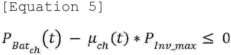


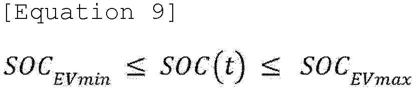


- The first condition may be implemented as
Equation 2, and functions to ensure that the decision variables Pgrid(t), PBatch (t), PBatdch (t), PEVch (t) , and PEVdch (t) are determined to balance the supply and demand of electric power. - The second condition may be implemented as Equation 3, and functions to determine that the SOC of the ESS battery in the next time interval is determined based on the capacity of the ESS battery and the charge and discharge efficiency of the power conversion device.
- The third condition may be implemented as
Equation 4, and functions to ensure that the SOC of the ESS battery is determined within a set threshold range. - The fourth and fifth conditions may be implemented as
Equations 5 to 7, and function to ensure that the decision variables PBatch (t) and PBatdch (t) do not exceed the power limit of the power conversion device (for example, an inverter), and that the amount of charge power and the amount of discharge power cannot be determined simultaneously. - The sixth condition may be implemented as Equation 8 and functions to determine the SOC of the EV battery in the next time interval based on the capacity of the EV battery and the charge/discharge efficiency of the bidirectional EV charger.
- The seventh condition may be implemented as Equation 9, and functions to ensure that the SOC of the EV battery is determined within a set threshold range. Herein, one or more of the lower limit value of SOC and the upper limit value of SOC of the EV battery may be set by the user. For example, the lower limit value of the SOC of the EV battery may be defined as a minimum guaranteed SOC of the EV battery received from the user terminal. According to the operation schedule derived from the objective function reflecting the seventh condition, the EV battery may perform a charge/discharge operation at a state of the minimum guaranteed SOC or more.
- The eighth and ninth conditions may be implemented as Equation 10 to 12, and function to ensure that the decision variables PEV
ch (t) and PEVdch (t) do not exceed the power limit of the bidirectional EV charger, and that the amount of charge power and the amount of discharge power cannot be determined simultaneously. - The EV connection state value βEV, reflected in Equations 10 and 11, may be defined as [1] in the connection state and [0] for the disconnection state. Herein, the EV connection state value may be defined based on the EV schedule information received from the user terminal.
- On the other hand, when the plurality of loads includes one or more second loads (loads that may be controlled on and off),
Equation 2 may be modified as represented in Equations 13 and 14 below.
p (t) is the predictive amount of power consumption of the first load, and Pload_np (t) is the predictive amount of power consumption of the second load)
- When the loads include the first load and the second load, in S420, the energy management device may generate the predictive amount of power consumption for the first load and the predictive amount of power consumption for the second load. Herein, the first condition regarding the balance of power supply and power consumption may reflect an on-off schedule of the second load, as represented in Equation 13.
- The on-off state value β load_n of the load reflected in Equation 14 may be defined as [1] for the on state and [0] for the off state. Herein, the on-off state value of the load may be defined based on the load schedule information received from the user terminal.
- The energy management device may derive Pgrid(t), PBat
ch (t), PBatdch (t), PEVch (t), and PEVdch (t) satisfying the objective function and the constraints (the first condition to the ninth condition), and generate an ESS operation schedule including PBatch (t) and PBatdch (t), and an EV operation schedule including PEVch (t) and PEVdch (t). In the meantime, the objective function and the constraints for the operation schedule establishment may have various modified examples, and the rights of the present invention are not limited to Equations described above. -
FIG. 5 is a diagram illustrating an example screen of a user terminal for explaining EV schedule information according to the exemplary embodiment of the present invention. - The energy management device may receive the minimum guaranteed SOC and the EV schedule information from the user terminal, and may generate an operation schedule based on the received minimum guaranteed SOC and EV schedule information.
- More specifically, the user terminal may receive, via a predefined Graphical User Interface (GUI), input of the minimum guaranteed SOC and the EV schedule information for the EV battery from the user.
- For example, as illustrated in
FIG. 5 , the user terminal may receive, from the user, a specific SOC value (75%) as a minimum guaranteed SOC and EV schedule information for time intervals (Time 1: 00:00 to 07:00, Time 2: 17:00 to 19:00, and Time 3: 21:00 to 24:00) during which the EV is connected to the bidirectional EV charger. Then, the user terminal may transmit the minimum guaranteed SOC and the EV schedule information input by the user to the energy management device. - The energy management device may reflect the minimum guaranteed SOC received from the user terminal in the seventh condition (Equation 9) among the constraints for deriving the operation schedule. Further, the energy management device may reflect the EV schedule information received from the user terminal in the eighth and ninth conditions (Equations 10 and 11) among the constraints for deriving the operation schedule.
- The energy management device may derive Pgrid(t), PBat
ch (t), PBatdch (t), PEVch (t), and PEVdch (t) satisfying the objective function according toEquation 1 and the constraints (the first condition to the ninth condition) reflecting the information received from the user terminal, and generate an ESS operation schedule including PBatch (t) and PBatdch (t), and an EV operation schedule including PEVch (t) and PEVdch (t). -
FIG. 6 is a diagram illustrating an example screen of a user terminal for explaining load schedule information according to the exemplary embodiment of the present invention. - The energy management device may receive, from a user terminal, load schedule information for an on-off controllable load, in which a time interval for operating the load in an on state or an off state is set, and generate an operation schedule based on the received load schedule information.
- More specifically, the user terminal may receive, via a predefined GUI, load schedule information for the second load.
- For example, as illustrated in
FIG. 6 , the user terminal may output a list of second loads (Loads Load 1 to Load N). The user terminal may then receive, from the user, information about the time interval during which each of the second loads operates in an on state or off state ([Load 4, 14:00 to 16:00, on], [Load 5, 15:00 to 18:00, on], [Load 6, 12:00 to 13:00, on], and [Load 7, 14:00 to 18:00, off]). - Then, the user terminal may transmit the load schedule information input by the user to the energy management device.
- The energy management device may control the on-off state of the second load based on the load schedule information received from the user terminal. For example, the energy management device may switch the
load 4 from an off state to an on state at 14:00 and switch theload 4 from an on state to an off state at 16:00. Further, the energy management device may switch theload 7 from an on state to an off state at 14:00 and switch theload 7 from an off state to an on state at 18:00. - The energy management device may reflect the load schedule information received from the user terminal in the first condition (Equations 13 and 14) among the constraints for deriving the operation schedule.
- The energy management device may derive Pgrid(t), PBat
ch (t), PBatdch (t), PEVch (t), and PEVdch (t) satisfying the objective function according toEquation 1 and the constraints (the first condition to the ninth condition) reflecting the information received from the user terminal, and generate an ESS operation schedule including PBatch (t) and PBatdch (t), and an EV operation schedule including PEVch (t) and PEVdch (t). -
FIG. 7 is a block diagram illustrating an energy management device according to an exemplary embodiment of the present invention. - The
energy management device 600 according to the exemplary embodiment of the present invention may be configured while being included within the energy storage system, or may be separate and external to the energy storage system. For example, theenergy management device 600 may be implemented while being included in the HEMS, which is the top-level control system of the residential ESS, or may be implemented while being included in a server of an ESS management company and configured to be connected with the HEMS via a network. - The
energy management device 600 may include at least oneprocessor 610, amemory 620 storing at least one instruction executed via the processor, and atransceiving device 630 performing communication via network connection. - The at least one instruction may include: an instruction for collecting basic information including information regarding a power generation state and a power consumption state, and grid electric power cost information; an instruction for establishing, by using the collected basic information, an ESS operation schedule for controlling the charging and discharging operations of the ESS battery and an EV operation schedule for controlling the charging and discharging operations of the EV battery; and an instruction for controlling the ESS battery and the EV battery to be charged/discharged in accordance with the ESS operation schedule and the EV operation schedule.
- The instruction for establishing the operation schedule may include an instruction for deriving the amount of charge and discharge of the ESS battery per time interval, and the amount of charge and discharge of the EV battery per time interval, which minimize the cost of purchasing grid electric power.
- The instruction for establishing the ESS operation schedule and the EV operation schedule may include an instruction for deriving, by using an objective function defined by the cost of purchasing grid electric power, the amount of charge and discharge of the ESS battery per time interval and the amount of charge and discharge of the EV battery per time interval.
- The objective function may include defined constraints including at least one of a first condition regarding a balance of power supply and power consumption, a second condition regarding a state of charge (SOC) based on charge/discharge efficiency of the ESS battery, a third condition regarding the amount of limit charge of the ESS battery, a fourth condition regarding a limit output of the power conversion device, and a fifth condition regarding a binarization of the charge/discharge state of the ESS battery. Herein, the constraint may further include at least one of a sixth condition regarding a state of charge (SOC) according to charge/discharge efficiency of the EV battery, a seventh condition regarding the amount of limit charge of the EV battery, an eighth condition regarding a limit output of the bidirectional EV charger, and a ninth condition regarding a binarization of the charge/discharge state of the bidirectional EV charger.
- The instruction for collecting the basic information may include an instruction for collecting basic information including information regarding a power generation state and a power consumption state for a predefined first period. Herein, the instruction for establishing the ESS operation schedule and the EV operation schedule may include: an instruction for generating, by using the collected basic information, power generation predictive information and power consumption predictive information for a second period predefined as a period after the first period; and an instruction for generating an ESS operation schedule and an EV operation schedule for the second period based on the generated predictive information.
- The instruction for collecting the basic information may include an instruction for receiving, from the user terminal, load schedule information, for an on-off controllable load, in which a time interval for operating a load in an on state or an off state is set. Herein, the instruction for establishing the ESS operation schedule and the EV operation schedule may include an instruction for generating the ESS operation schedule and the EV operation schedule based on the load schedule information.
- The instruction for collecting the basic information may include an instruction for receiving, from the user terminal, EV schedule information, in which a time interval during which the EV is connected to the bidirectional EV charger is set. Herein, the instruction for establishing the ESS operation schedule and the EV operation schedule may include an instruction for generating the ESS operation schedule and the EV operation schedule based on the EV schedule information.
- The instruction for controlling the ESS battery and the EV battery to be charged/discharged may include an instruction for providing the ESS operation schedule to a power conversion device interworking with the ESS battery and providing the EV operation schedule to the bidirectional EV charger, to cause the ESS battery to be charged and discharged in accordance with the ESS operation schedule, and cause the EV battery to be charged and discharged in accordance with the EV operation schedule.
- The
energy management device 600 may further include aninput interface device 640, anoutput interface device 650, astorage device 660, and the like. Each of the components included in theenergy management device 600 may be connected by abus 670 to communicate with each other. - Herein, the
processor 610 may refer to a Central Processing Unit (CPU), a Graphics Processing Unit (GPU), or a dedicated processor on which the methods according to the exemplary embodiments of the present invention are performed. The memory (or storage device) may be formed of at least one of a volatile storage medium and a non-volatile storage medium. For example, the memory may be formed of at least one of Read Only Memory (ROM) and Random Access Memory (RAM). - The operation of the method according to the exemplary embodiment of the present invention may be implemented as a computer-readable program or code on a computer-readable recording medium. The computer-readable recording medium includes all types of recording devices in which data readable by a computer system is stored. In addition, the computer-readable recording medium may be distributed in a networkconnected computer system to store and execute computer-readable programs or codes in a distributed manner.
- Although some aspects of the invention have been described in the context of the device, it may also represent a description according to a corresponding method, wherein a block or device corresponds to a method step or feature of a method step. Similarly, aspects described in the context of a method may also represent a feature of a corresponding block or item or a corresponding device. Some or all of the method steps may be performed by (or using) a hardware device, such as, for example, a microprocessor, a programmable computer, or an electronic circuit. In some exemplary embodiments, one or more of the most important method steps may be performed by such a device.
- In the forgoing, the present invention has been described with reference to the exemplary embodiment of the present invention, but those skilled in the art may appreciate that the present invention may be variously corrected and changed within the range without departing from the spirit and the area of the present invention described in the appending claims.
Claims (18)
- An energy management device that interworks with an electric power grid, a power generation device, an Energy Storage System ESS, and a bidirectional Electric Vehicle EV charger, the energy management device comprising:at least one processor; anda memory for storing at least one instruction executed via the at least one processor,wherein the at least one instruction includes:an instruction for collecting basic information including information regarding a power generation state and a power consumption state, and grid electric power cost information;an instruction for establishing, by using the collected basic information, an ESS operation schedule for controlling charging and discharging operations of an ESS battery and an EV operation schedule for controlling charging and discharging operations of an EV battery; andan instruction for controlling the ESS battery and the EV battery to be charged/discharged in accordance with the ESS operation schedule and the EV operation schedule.
- The energy management device of claim 1, wherein the instruction for establishing the ESS operation schedule and the EV operation schedule includes an instruction for deriving the amount of charge and discharge of the ESS battery per time interval, and the amount of charge and discharge of the EV battery per time interval, which minimize costs of purchasing grid electric power.
- The energy management device of claim 1, wherein the instruction for establishing the ESS operation schedule and the EV operation schedule includes an instruction for deriving, by using an objective function defined by the costs of purchasing the grid electric power, the amount of charge and discharge of the ESS battery per time interval and the amount of charge and discharge of the EV battery per time interval.
- The energy management device of claim 3, wherein the objective function includes defined constraints including at least one of a first condition regarding a balance of power supply and power consumption, a second condition regarding a State Of Charge SOC based on charge/discharge efficiency of the ESS battery, a third condition regarding the amount of limit charge of the ESS battery, a fourth condition regarding a limit output of the power conversion device, and a fifth condition regarding a binarization of the charge/discharge state of the ESS battery.
- The energy management device of claim 4, wherein the constraints further include at least one of a sixth condition regarding an SOC according to charge/discharge efficiency of the EV battery, a seventh condition regarding the amount of limit charge of the EV battery, an eighth condition regarding a limit output of the bidirectional EV charger, and a ninth condition regarding a binarization of the charge/discharge state of the bidirectional EV charger.
- The energy management device of claim 1, wherein the instruction for collecting the basic information includes an instruction for collecting basic information including information regarding a power generation state and a power consumption state for a predefined first period, and
the instruction for establishing the ESS operation schedule and the EV operation schedule includes:an instruction for generating, by using the collected basic information, power generation predictive information and power consumption predictive information for a second period predefined as a period after the first period; andan instruction for generating an ESS operation schedule and an EV operation schedule for the second period based on the generated predictive information. - The energy management device of claim 1, wherein the instruction for collecting the basic information includes an instruction for receiving, from a user terminal, load schedule information, for an on-off controllable load, in which a time interval for operating a load in an on state or an off state is set, and
the instruction for establishing the ESS operation schedule and the EV operation schedule includes an instruction for generating the ESS operation schedule and the EV operation schedule based on the load schedule information. - The energy management device of claim 1, wherein the instruction for collecting the basic information includes an instruction for receiving, from a user terminal, EV schedule information, in which a time interval during which an EV is connected to a bidirectional EV charger is set, and
the instruction for establishing the ESS operation schedule and the EV operation schedule includes an instruction for generating the ESS operation schedule and the EV operation schedule based on the EV schedule information. - The energy management device of claim 1, wherein the instruction for controlling the ESS battery and the EV battery to be charged/discharged includes an instruction for providing the ESS operation schedule to a power conversion device interworking with the ESS battery and providing the EV operation schedule to the bidirectional EV charger to cause the ESS battery to be charged and discharged in accordance with the ESS operation schedule, and cause the EV battery to be charged and discharged in accordance with the EV operation schedule.
- An energy management method by an energy management device that interworks with an electric power grid, a power generation device, an Energy Storage System ESS, and a bidirectional Electric Vehicle EV charger, the energy management method comprising:collecting basic information including information regarding a power generation state and a power consumption state, and grid electric power cost information;establishing, by using the collected basic information, an ESS operation schedule for controlling charging and discharging operations of an ESS battery and an EV operation schedule for controlling charging and discharging operations of an EV battery; andcontrolling the ESS battery and the EV battery to be charged/discharged in accordance with the ESS operation schedule and the EV operation schedule.
- The energy management method of claim 10, wherein the establishing of the ESS operation schedule and the EV operation schedule includes deriving the amount of charge and discharge of the ESS battery per time interval, and the amount of charge and discharge of the EV battery per time interval, which minimize costs of purchasing grid electric power.
- The energy management method of claim 10, wherein the establishing of the ESS operation schedule and the EV operation schedule includes deriving, by using an objective function defined by the costs of purchasing the grid electric power, the amount of charge and discharge of the ESS battery per time interval and the amount of charge and discharge of the EV battery per time interval.
- The energy management method of claim 12, wherein the objective function includes defined constraints including at least one of a first condition regarding a balance of power supply and power consumption, a second condition regarding a State Of Charge SOC based on charge/discharge efficiency of the ESS battery, a third condition regarding the amount of limit charge of the ESS battery, a fourth condition regarding a limit output of the power conversion device, and a fifth condition regarding a binarization of the charge/discharge state of the ESS battery.
- The energy management method of claim 13, wherein the constraints further include at least one of a sixth condition regarding an SOC according to charge/discharge efficiency of the EV battery, a seventh condition regarding the amount of limit charge of the EV battery, an eighth condition regarding a limit output of the bidirectional EV charger, and a ninth condition regarding a binarization of the charge/discharge state of the bidirectional EV charger.
- The energy management method of claim 10, wherein the collecting of the basic information includes collecting basic information including information regarding a power generation state and a power consumption state for a predefined first period, and
the establishing of the ESS operation schedule and the EV operation schedule includes:generating, by using the collected basic information, power generation predictive information and power consumption predictive information for a second period predefined as a period after the first period; andgenerating an ESS operation schedule and an EV operation schedule for the second period based on the generated predictive information. - The energy management method of claim 10, wherein the collecting of the basic information includes receiving, from a user terminal, load schedule information, for an on-off controllable load, in which a time interval for operating a load in an on state or an off state is set, and
the establishing of the ESS operation schedule and the EV operation schedule includes generating the ESS operation schedule and the EV operation schedule based on the load schedule information. - The energy management method of claim 10, wherein the collecting of the basic information includes receiving, from a user terminal, EV schedule information, in which a time interval during which an EV is connected to a bidirectional EV charger is set, and
the establishing of the ESS operation schedule and the EV operation schedule includes generating the ESS operation schedule and the EV operation schedule based on the EV schedule information. - The energy management method of claim 10, wherein the controlling of the ESS battery and the EV battery to be charged/discharged includes providing the ESS operation schedule to a power conversion device interworking with the ESS battery and providing the EV operation schedule to the bidirectional EV charger to cause the ESS battery to be charged and discharged in accordance with the ESS operation schedule, and cause the EV battery to be charged and discharged in accordance with the EV operation schedule.
Applications Claiming Priority (2)
| Application Number | Priority Date | Filing Date | Title |
|---|---|---|---|
| KR1020230101159A KR20250021156A (en) | 2023-08-02 | 2023-08-02 | Energy management device and method |
| PCT/KR2024/010808 WO2025028910A1 (en) | 2023-08-02 | 2024-07-25 | Energy management device and energy management method |
Publications (1)
| Publication Number | Publication Date |
|---|---|
| EP4557569A1 true EP4557569A1 (en) | 2025-05-21 |
Family
ID=94395481
Family Applications (1)
| Application Number | Title | Priority Date | Filing Date |
|---|---|---|---|
| EP24849479.1A Pending EP4557569A1 (en) | 2023-08-02 | 2024-07-25 | Energy management device and energy management method |
Country Status (6)
| Country | Link |
|---|---|
| US (1) | US20260081451A1 (en) |
| EP (1) | EP4557569A1 (en) |
| JP (1) | JP2025528270A (en) |
| KR (1) | KR20250021156A (en) |
| CN (1) | CN119856365A (en) |
| WO (1) | WO2025028910A1 (en) |
Family Cites Families (11)
| Publication number | Priority date | Publication date | Assignee | Title |
|---|---|---|---|---|
| JP5672186B2 (en) * | 2011-07-24 | 2015-02-18 | 株式会社デンソー | Power supply system |
| KR101380530B1 (en) | 2011-10-12 | 2014-04-01 | (주)에스엔디파워닉스 | Grid-connected energy storaging system |
| JP6280687B2 (en) * | 2012-09-05 | 2018-02-14 | 株式会社日立製作所 | Charging / discharging system and charging / discharging device |
| US10705496B2 (en) * | 2016-08-05 | 2020-07-07 | Lg Electronics Inc. | Control device of home energy management system |
| KR20190000038A (en) * | 2017-06-22 | 2019-01-02 | 한국전기연구원 | Method of optimum power demand management using electric vehicle and apparatus thereof |
| KR102469243B1 (en) * | 2020-11-27 | 2022-11-23 | 한국에너지기술연구원 | Electric vehicle charging system |
| KR102553039B1 (en) * | 2021-05-14 | 2023-07-06 | 서울과학기술대학교 산학협력단 | Centralized Power Flow Control and Operation Method of EV-connected DC Microgrid for Multi Objective Optimization |
| JP2024518404A (en) * | 2021-05-14 | 2024-05-01 | ヴェローチェ エナジー、インコーポレイテッド | Systems and methods for electric vehicle charging power distribution |
| KR102639174B1 (en) * | 2021-12-01 | 2024-02-21 | 주식회사 피엠그로우 | Battery scheduling method performing scheduling for battery usage of electric vehicla based on energy storage system and apparatus therefor |
| JP7786199B2 (en) * | 2021-12-27 | 2025-12-16 | 住友電気工業株式会社 | Method for creating a power processing instruction schedule, computer program, and computer |
| KR20230101159A (en) | 2021-12-29 | 2023-07-06 | 주식회사 아이브이에스 | Multi layered tube and manufacturing method of multi layered tube |
-
2023
- 2023-08-02 KR KR1020230101159A patent/KR20250021156A/en active Pending
-
2024
- 2024-07-25 WO PCT/KR2024/010808 patent/WO2025028910A1/en active Pending
- 2024-07-25 US US19/110,714 patent/US20260081451A1/en active Pending
- 2024-07-25 CN CN202480003930.4A patent/CN119856365A/en active Pending
- 2024-07-25 JP JP2025512767A patent/JP2025528270A/en active Pending
- 2024-07-25 EP EP24849479.1A patent/EP4557569A1/en active Pending
Also Published As
| Publication number | Publication date |
|---|---|
| JP2025528270A (en) | 2025-08-26 |
| US20260081451A1 (en) | 2026-03-19 |
| WO2025028910A1 (en) | 2025-02-06 |
| CN119856365A (en) | 2025-04-18 |
| KR20250021156A (en) | 2025-02-12 |
Similar Documents
| Publication | Publication Date | Title |
|---|---|---|
| Goebel et al. | Model-based dispatch strategies for lithium-ion battery energy storage applied to pay-as-bid markets for secondary reserve | |
| Schreiber et al. | Practical and commercial issues in the design and manufacture of vanadium flow batteries | |
| EP2639919B1 (en) | Electric power supply-and-demand control apparatus | |
| US9098817B2 (en) | Method for real-time control of energy storage units to reduce electricity cost | |
| US20230148201A1 (en) | Method and system for supplying power to device, and related device | |
| US20240383361A1 (en) | Energy storage system interworking with solar power generation system and electric vehicle charging system and method for operating same | |
| KR101530679B1 (en) | Apparatus for energy management considering degration of battery and method thereof | |
| KR20140128468A (en) | Apparatus and method for battery balancing | |
| Xu et al. | Multi-objective chance-constrained optimal day-ahead scheduling considering BESS degradation | |
| US12571852B2 (en) | Battery life prediction apparatus and method | |
| US12556003B2 (en) | Energy storage system for optimum operation of demand response resource and operating method thereof | |
| JP5422021B2 (en) | Power storage system | |
| Ananda-Rao et al. | Battery energy storage system assessment in a designed battery controller for load leveling and peak shaving applications | |
| EP4632988A1 (en) | Operation support device and method of energy storage system | |
| KR102064586B1 (en) | Charge management method for energy storage system | |
| EP4280052B1 (en) | Firmware update system of battery management system, and method related thereto | |
| Hasaranga et al. | A Fuzzy logic based battery SOC level control strategy for smart Micro grid | |
| EP4557569A1 (en) | Energy management device and energy management method | |
| Hooshmand et al. | A power management system for planned & unplanned grid electricity outages | |
| Gangwar et al. | Planning and dispatch of battery energy storage in microgrid for cycle-life improvement | |
| EP4712292A1 (en) | Operation support apparatus and method for energy storage system | |
| KR20250017372A (en) | Apparatus and method for controlling operation of electric vehicle charger | |
| GÓRSKI et al. | Preliminary techno-economic analysis of electrochemical cell types applied to stationary energy storage systems | |
| KR20250161852A (en) | Energy storage system and operating method thereof | |
| IURILLI | Modelling and analysis of battery energy storage systems for primary control reserve provision |
Legal Events
| Date | Code | Title | Description |
|---|---|---|---|
| STAA | Information on the status of an ep patent application or granted ep patent |
Free format text: STATUS: THE INTERNATIONAL PUBLICATION HAS BEEN MADE |
|
| PUAI | Public reference made under article 153(3) epc to a published international application that has entered the european phase |
Free format text: ORIGINAL CODE: 0009012 |
|
| STAA | Information on the status of an ep patent application or granted ep patent |
Free format text: STATUS: REQUEST FOR EXAMINATION WAS MADE |
|
| 17P | Request for examination filed |
Effective date: 20250214 |
|
| AK | Designated contracting states |
Kind code of ref document: A1 Designated state(s): AL AT BE BG CH CY CZ DE DK EE ES FI FR GB GR HR HU IE IS IT LI LT LU LV MC ME MK MT NL NO PL PT RO RS SE SI SK SM TR |