JP6280687B2 - Charging / discharging system and charging / discharging device - Google Patents
Charging / discharging system and charging / discharging device Download PDFInfo
- Publication number
- JP6280687B2 JP6280687B2 JP2012195220A JP2012195220A JP6280687B2 JP 6280687 B2 JP6280687 B2 JP 6280687B2 JP 2012195220 A JP2012195220 A JP 2012195220A JP 2012195220 A JP2012195220 A JP 2012195220A JP 6280687 B2 JP6280687 B2 JP 6280687B2
- Authority
- JP
- Japan
- Prior art keywords
- power
- charging
- charge
- discharge
- electric vehicle
- Prior art date
- Legal status (The legal status is an assumption and is not a legal conclusion. Google has not performed a legal analysis and makes no representation as to the accuracy of the status listed.)
- Active
Links
Images


Classifications
-
- Y—GENERAL TAGGING OF NEW TECHNOLOGICAL DEVELOPMENTS; GENERAL TAGGING OF CROSS-SECTIONAL TECHNOLOGIES SPANNING OVER SEVERAL SECTIONS OF THE IPC; TECHNICAL SUBJECTS COVERED BY FORMER USPC CROSS-REFERENCE ART COLLECTIONS [XRACs] AND DIGESTS
- Y02—TECHNOLOGIES OR APPLICATIONS FOR MITIGATION OR ADAPTATION AGAINST CLIMATE CHANGE
- Y02B—CLIMATE CHANGE MITIGATION TECHNOLOGIES RELATED TO BUILDINGS, e.g. HOUSING, HOUSE APPLIANCES OR RELATED END-USER APPLICATIONS
- Y02B10/00—Integration of renewable energy sources in buildings
- Y02B10/10—Photovoltaic [PV]
-
- Y—GENERAL TAGGING OF NEW TECHNOLOGICAL DEVELOPMENTS; GENERAL TAGGING OF CROSS-SECTIONAL TECHNOLOGIES SPANNING OVER SEVERAL SECTIONS OF THE IPC; TECHNICAL SUBJECTS COVERED BY FORMER USPC CROSS-REFERENCE ART COLLECTIONS [XRACs] AND DIGESTS
- Y02—TECHNOLOGIES OR APPLICATIONS FOR MITIGATION OR ADAPTATION AGAINST CLIMATE CHANGE
- Y02E—REDUCTION OF GREENHOUSE GAS [GHG] EMISSIONS, RELATED TO ENERGY GENERATION, TRANSMISSION OR DISTRIBUTION
- Y02E60/00—Enabling technologies; Technologies with a potential or indirect contribution to GHG emissions mitigation
- Y02E60/10—Energy storage using batteries
Landscapes
- Supply And Distribution Of Alternating Current (AREA)
- Charge And Discharge Circuits For Batteries Or The Like (AREA)
- Secondary Cells (AREA)
- Electric Propulsion And Braking For Vehicles (AREA)
Description
本発明は、電気自動車に電力を充電し、かつ電気自動車に充電した電力を放電させる充放電システム、充放電装置および充放電制御方法に関する。 The present invention relates to a charging / discharging system, a charging / discharging device, and a charging / discharging control method for charging an electric vehicle with electric power and discharging electric power charged with the electric vehicle.
近年、バッテリーから供給される電力によりモータを駆動して走行する電気自動車が使用されるようになり、バッテリーに充電するために家庭用のコンセントを用いる事例や、逆にバッテリーに充電された電力を用いて家庭用電気機器に供給する事例が知られている。特許文献1では、家庭用のコンセント(電源ソケット)を用いてバッテリーに充電する場合に、宅内の電流使用量が制限器(アンペアブレーカ)の上限値を超過して停電したとき、電力供給の再開後にバッテリーへの充電動作を制限する充電制限手段と、所定条件が満足されると上記制限を解除する制限解除手段とを備えることで、制限器の動作によって再度停電が生じるのを抑制する構成が記載されている。
In recent years, electric vehicles that run by driving a motor with electric power supplied from a battery have been used, and examples of using a household outlet to charge the battery, and conversely, the electric power charged in the battery Examples of using and supplying to household electrical equipment are known. In
前記特許文献1には、バッテリーへの充電動作における電流使用量が制限器(ブレーカ)の上限値を超えないよう制御する技術が記載されている。しかしながら、電気自動車のバッテリーに充電された電力を家庭用電気機器に供給する場合を想定すると、家庭用コンセント(系統電力)と電気自動車と電気機器との間の電力需給バランスを考慮する必要がある。さらに、太陽光発電電力等の再生可能エネルギーを使用して電気自動車に充電するシステムでは、電力をより効率的に供給させるためにきめ細かな制御が必要になってくる。
そこで本発明は、電気自動車への充電だけでなく、電気自動車から放電された電力を電気機器に効率的に供給する充放電システム及び充放電装置を提供することを目的とする。 Therefore, an object of the present invention is to provide a charging / discharging system and a charging / discharging device that efficiently supply not only charging of an electric vehicle but also electric power discharged from the electric vehicle to an electric device.
上記課題を解決するために、特許請求の範囲に記載の構成を採用する。その一例を挙げれば、本発明は、電力供給源から電気自動車に電力を充電し、電気自動車に充電した電力を放電する充放電システムであって、電力供給源と電気自動車に接続され電気自動車に対し充放電を行う充放電装置と、充放電装置の充放電動作を制御する制御装置とを有し、電気自動車は現在の充電量を充放電装置に送信し、充放電装置は受信した充電量を制御装置に送信し、制御装置は受信した充電量が所定の値に到達したときに充放電動作を停止させる。ここに電力供給源として系統電力を入力する分電装置と太陽光発電装置を備え、充放電装置は電気自動車から放電された電力を分電装置を介して電気機器に供給する構成とする。 In order to solve the above problems, the configuration described in the claims is adopted. For example, the present invention is a charging / discharging system that charges an electric vehicle from an electric power supply source and discharges the electric power charged in the electric vehicle, and is connected to the electric power source and the electric vehicle. A charging / discharging device that performs charging / discharging, and a control device that controls the charging / discharging operation of the charging / discharging device, the electric vehicle transmits the current charging amount to the charging / discharging device, and the charging / discharging device receives the charging amount Is transmitted to the control device, and the control device stops the charge / discharge operation when the received charge amount reaches a predetermined value. Here, the power distribution source includes a power distribution device that inputs system power and a solar power generation device, and the charging / discharging device is configured to supply power discharged from the electric vehicle to the electric device via the power distribution device.
本発明によれば、電気自動車に充電した電力を電気機器に供給することにより、家庭内における電力消費の平準化を図ることが可能となる。さらに、太陽光発電電力を使用することで、系統電力からの電力消費量の削減を図ることが可能となる。 ADVANTAGE OF THE INVENTION According to this invention, it becomes possible to aim at the equalization of the power consumption in a household by supplying the electric power charged to the electric vehicle to an electric equipment. Furthermore, it is possible to reduce power consumption from the grid power by using solar power.
以下、本発明の実施例について図面を用いて説明する。なお、各図面において同一符号は、同一の要素または相当する要素を示す。 Embodiments of the present invention will be described below with reference to the drawings. In each drawing, the same numerals indicate the same or corresponding elements.
図1は、本発明による充放電システムの一実施例を示す全体構成図である。本実施例の充放電システム1では、系統電力(商用電力)や太陽光発電電力を電力供給源として電気自動車5に充電し、電気自動車5に充電した電力を放電して家庭内の電気機器8に供給する構成としている。充放電システム1は、充放電装置2、分電装置3、制御装置4、電気自動車5、太陽光発電装置6、電池7、電気機器8、サーバ9、ネットワーク10を備える。図中、実線は電力線を、破線は通信線を表す。
FIG. 1 is an overall configuration diagram showing an embodiment of a charge / discharge system according to the present invention. In the charging /
系統電力から入力した電力は、分電装置3を介し充放電装置2、電気機器8、電池7に供給される。太陽光発電装置6で発電された電力は、充放電装置2を介し分電装置3や電気自動車5に供給される。充放電装置2は、分電装置3や太陽光発電装置6から入力した電力を電気自動車5の電池を充電するために供給する。逆に、電気自動車5の電池を放電させたときの電力は、充放電装置2と分電装置3を介して電気機器8や電池7に供給される。充放電装置2は、分電装置3と入出力する電力、太陽光発電装置6から入力される電力、および電気自動車5と入出力する電力について、入力電力の和と出力電力の和を等値にするよう調整する。電池7は、必要に応じ充放電装置2を動作するための電力を供給する。なお、電池7は充放電装置2に内蔵してもよい。
The power input from the system power is supplied to the charging /
制御装置4は、ネットワーク10を介して接続されたサーバ9から、後述する電気自動車5の利用計画情報を入手し、入手した利用計画に従い充放電装置2に充放電動作を指示する。充放電装置2と電気自動車5は電力線と通信線で接続され、充放電装置2の指示に従い電気自動車5に電力を入出力(充放電)する。分電装置3と充放電装置2は通信線で接続され、分電装置3は系統電力の停電を検知して充放電装置2に伝える。あるいは分電装置3は、充放電装置2から出力される電力が分電装置3に接続された電気機器8の消費電力よりも大きくなり、系統電力へ電力が出力されることを検知して充放電装置2に伝える。
The
本実施例の充放電システムによれば、電気自動車5に充電した電力を家庭内の電気機器の電力源として利用するので、家庭内における電力消費の平準化を図ることが可能となる。さらに、太陽光発電電力を使用することで、系統電力からの電力消費量の削減を図ることが可能となる。
According to the charging / discharging system of the present embodiment, the electric power charged in the
以下、各装置の内部構成を詳細に説明する。
図2は、充放電装置2の構成例を示すブロック図である。充放電装置2は、太陽光発電入力部20、系統電力入出力部21、自動車電力入出力部22、DC−DC電力変換部23a、AC−DC電力変換部23b、DC−DC電力変換部23c、分電装置通信部24、制御部25、自動車通信部26、制御装置通信部27、電池電力入力部28、ロック部29を備える。実線は電力線、破線は通信線を表す。
Hereinafter, the internal configuration of each apparatus will be described in detail.
FIG. 2 is a block diagram illustrating a configuration example of the charge /
太陽光発電装置6で発電された電力は太陽光発電入力部20に入力され、DC−DC電力変換部23aで所定の直流電流に変換し、AC−DC電力変換部23bまたはDC−DC電力変換部23cに出力する。
The electric power generated by the solar
電気自動車5に充電する場合、分電装置3から系統電力入出力部21に入力された交流電流はAC−DC電力変換部23bで所定の直流電流に変換し、DC−DC電力変換部23Cに出力する。DC−DC電力変換部23Cでは、入力された直流電流を所定の直流電流に変換し、自動車電力入出力部22から電気自動車5に出力する。
When charging the
電気自動車5から放電する場合、電気自動車5から出力された直流電流は自動車電力入出力部22に入力される。そして、DC−DC電力変換部23Cで所定の直流電流に変換し、AC−DC電力変換部23bで所定の交流電流に変換して、分電装置3に出力される。
When discharging from the
分電装置通信部24は分電装置3と接続し、停電発生、系統復帰等のイベントを受信する。自動車通信部26は電気自動車5と接続し、充電、放電制御に関する情報を送受信する。制御装置通信部27は制御装置4と接続し、充放電装置2の制御に関する情報を送受信する。例えば、電気自動車5から現在の充電量の情報を受信し、この情報を制御装置4へ送信する。ロック部29は電気自動車5と接続し、電気自動車5との間で電力および通信データを伝送するケーブルのコネクタをロックする。
The power distribution
制御部25は、分電装置通信部24、自動車通信部26、制御装置通信部27を介し各装置と通信を行うともに、ロック部29を制御する。また制御部25は、DC−DC電力変換部23a、AC−DC電力変換部23b、DC−DC電力変換部23Cを制御し、太陽光発電入力部20、系統電力入出力部21、自動車電力入出力部22における入力電力和と出力電力和を等値にするよう制御する。具体的には、
充電時:[系統入力電力]+[太陽光発電電力]=[自動車充電電力]
放電時:[太陽光発電電力]+[自動車放電電力]=[系統出力電力]
となるように制御する。例えば、系統出力電力が分電装置3に接続された電気機器8の電力消費よりも大きくなった場合、自動車放電電力を抑えて系統電力へ電力が出力されないように調整する。
電池7から入力された電力は電池電力入力部28に入力され、充放電装置2の動作電力に使用される。
The
When charging: [System input power] + [Solar power] = [Automobile charging power]
During discharge: [Solar power generation] + [Automobile discharge power] = [System output power]
Control to be For example, when the system output power becomes larger than the power consumption of the
The power input from the
このように充放電装置2では、制御部25による電力制御により、電気自動車5への充電および電気自動車からの放電を規定された条件でスムーズに行える。特に、電気自動車5から放電させた電力を電気機器8へ供給する場合、電気機器8の電力負荷に合わせて自動車放電電力を調整することで、需給バランスのとれた効率の良い電力制御を行うことができる。
Thus, in the charging / discharging
図3は、分電装置3の構成例を示すブロック図である。分電装置3は、系統電力入力部30、主幹ブレーカ31、第1のブレーカ32、第1の電力出力部33、第2のブレーカ34、第2の電力出力部35、充放電装置電力入出力部36、監視部37、充放電装置通信部38を備える。
FIG. 3 is a block diagram illustrating a configuration example of the
系統電力入力部30には系統電力(商用電力)が入力し、主幹ブレーカ31、第1のブレーカ32を介し、第1の電力出力部33から電気機器8に供給される。また第2のブレーカ34を介し、第2の電力出力部35から電気機器8に供給される。充放電装置電力入出力部36は充放電装置2と接続され、出力の場合は、主幹ブレーカ31から入力した電力を充放電装置2に出力し、入力の場合は、充放電装置2から入力した電力を第1のブレーカ32、第2のブレーカ34に出力する。
System power (commercial power) is input to the system
監視部37は、停電の発生、停電からの復帰、充放電装置2から入力された電力が主幹ブレーカ31を介し系統電力入力部30から出力されたことを検知し、充放電装置通信部38を介し充放電装置2に通知する。
The
図4は、制御装置4の構成例を示すブロック図である。制御装置4は、充放電装置通信部40、ネットワーク通信部41、制御部42、記憶部43、ユーザ操作入力部44、表示部45、電池46を備える。
FIG. 4 is a block diagram illustrating a configuration example of the
充放電装置通信部40は、充放電装置2との間で制御情報の送受信を行う。ネットワーク通信部41は、サーバ9から電気自動車5の車両利用に関する情報を入手する。ユーザ操作入力部44はマウス、タッチパネル、ボタン等で構成され、ユーザからの充放電システム1への操作が入力され、入力情報を制御部42に通知する。表示部45は、充放電システム1の動作状態に関する情報を表示する。
The charging / discharging
制御部42は、サーバ9から入手した車両利用情報、太陽光発電装置6の発電計画、電気機器8の電力消費予測をもとに、電気自動車5に対する充放電制御計画を作成する。作成した充放電制御計画は、記憶部43に実行プログラムとして格納する。そして、記憶部43に記憶したプログラムを読み出して、規定の時刻になると規定の充放電動作を実行させる。その際、充放電装置通信部40、ネットワーク通信部41、ユーザ操作入力部44、表示部45を介して、他の装置やユーザに指示や通知を与える。また、充放電装置2を介して電気自動車5の現在の充電量を取得し、これが予め定めた所定の充電量に到達したとき、現在の充放電動作を停止させる。
電池46は、停電時あるいはコンセント(図示せず)から電力を供給しない場合に、制御装置4を駆動させるための電力を供給する。
The
The
このように制御装置4は、電気自動車5の利用情報、太陽光発電装置6の発電計画、電気機器8の電力消費予測をもとに作成した充放電制御計画に従い、電気自動車5に対する充放電動作の開始指示を行う。また電気自動車5の現在の充電量を取得して所定値に到達したとき充放電動作の停止指示を行う。これより、電気自動車5や電気機器8の利用に合わせて電力を効率的に供給し、家庭内における電力消費を平準化しかつ電力消費量の削減を図ることが可能となる。
As described above, the
図5は、電気自動車5の構成例を示すブロック図である。電気自動車5は、充放電装置通信部50、制御部51、ユーザ操作部52、充放電装置電力入出力部53、電池監視部54、電池(バッテリー)55、モータ56、駆動部57を備える。
FIG. 5 is a block diagram illustrating a configuration example of the
充放電装置通信部50は、充放電装置2との間で充放電に関する制御情報を送受信する。充放電装置電力入出力部53は、充放電装置2から入力された電力で電池55を充電し、逆に電池55から放電された電力を充放電装置2に出力する。モータ56は電池55から供給される電力で回転し、タイヤ等の駆動部57を駆動させる。
The charging / discharging
電池監視部54は電池55の充電状態(現在の充電量)を監視し、制御部51に通知する。ユーザ操作部52は入力されたユーザ操作を制御部51に通知する。制御部51はユーザ操作部52、電池監視部54、モータ56を制御し、現在の充電量やユーザ操作を充放電装置通信部50を介して充放電装置2へ送信する。
The
図6は、本実施例における充放電シーケンスの第1例(基本動作)を示す図である。ここでは制御装置4の指示により、充放電装置2から電気自動車5に充電動作を行う場合を説明する。
FIG. 6 is a diagram showing a first example (basic operation) of the charge / discharge sequence in the present embodiment. Here, the case where the charging operation from the charging / discharging
S601:制御装置4が充放電装置2に処理開始を通知する。
S602:充放電装置2は処理開始を通知されると、電気自動車5に処理開始を通知する。
S601: The
S602: When the charge /
S603:電気自動車5は処理開始を通知されると、充放電装置2に車両情報を送信する。
S604:充放電装置2は車両情報を受信すると、制御装置4に車両情報と充放電装置情報を送信する。
S603: When the
S604: When the charging / discharging
S605:制御装置4は車両情報と充放電装置情報を受信すると、車両識別、充放電装置識別を確認する。認証済の場合は、充放電装置2に充放電制御情報(ここでは充電制御情報)を送信する。未認証の場合は、ユーザに未認証であることを通知し終了する。
S606:充放電装置2は充放電制御情報を受信すると、電気自動車5に充放電装置情報を送信する。
S605: Upon receiving the vehicle information and the charging / discharging device information, the
S606: When the charge /
S607:電気自動車5は充放電装置情報を受信し、所定の処理を行うと、充放電装置2に準備完了通知を送信する。
S608:充放電装置2は準備完了通知を受信すると、制御装置4に充放電準備完了通知を送信する。
S607: The
S608: Upon receiving the preparation completion notification, the charge /
S609:制御装置4は充放電準備完了通知を受信すると、ユーザ操作あるいは所定の充放電計画に従い、充放電装置2に充電開始を通知する。
S610:充放電装置2は充電開始を受信すると、ロック部29によりコネクタロックを行う。そして、電気自動車5に充電開始を通知し、充電を開始する。
S609: Upon receipt of the charge / discharge preparation completion notification, the
S610: When the charging / discharging
S611:充電中、電気自動車5は充放電装置2に充電情報を送信する。
S612:充電中、充放電装置2は制御装置4に充電情報と充放電装置情報を送信する。
S611: During charging, the
S612: During charging, the charging / discharging
S613:充電中、制御装置4は充放電装置2に充放電制御情報を送信する。
S614:充電中、充放電装置2は電気自動車5に充放電装置情報を送信する。
充電中、S611からS614のシーケンスを繰り返す。
S613: During charging, the
S614: During charging, the charging / discharging
During charging, the sequence from S611 to S614 is repeated.
S615:電気自動車5は所定の充電量(満充電)に到達すると、充放電装置2に現在の動作(充電)の停止要求を通知する。
S616:充放電装置2は停止要求を受信すると、制御装置4に充電停止要求を送信する。
S615: When the
S616: Upon receiving the stop request, the charge /
S617:制御装置4は充電停止要求を受信すると、充放電装置2に現在の動作(充電)の停止を指示する。
S618:充放電装置2は充電を停止し、また停止したことを電気自動車5に通知する。
S617: When the
S618: The charging / discharging
S619:電気自動車5は停止を通知されると、所定の処理を行い充放電装置2に処理終了を通知する。充放電装置2は処理終了を受信すると、ロック部29によるコネクタロックを解除する。
S619: When the
なお、S615、S616において、電気自動車5は現在の充電量を充放電装置2を介して制御装置4に通知し、制御装置4は現在の充電量が所定の充電量に達したとき、S617において充放電装置2に対し充放電動作の停止を指示するようにしても良い。これは、後述の図8、図9のシーケンスにおいても同様である。
本シーケンスでは充電動作の場合を説明したが、放電動作の場合も同様の手順で実施される。
In S615 and S616, the
Although the case of the charging operation has been described in this sequence, the same procedure is performed in the case of the discharging operation.
図7は、充放電シーケンスの第2例を示す図であり、待機状態から充放電動作(ここでは放電)を開始する場合である。待機状態とは、充放電装置2と電気自動車5の間で電力の入出力、および通信情報の送受信がなく、ロック部29によりコネクタロックのみ行う状態である。待機状態とすることで、次の充放電動作を開始する際コネクタロックを行う必要がなく、スムーズに移行できる。
FIG. 7 is a diagram showing a second example of the charge / discharge sequence, in which the charge / discharge operation (discharge in this case) is started from the standby state. The standby state is a state where there is no input / output of power and transmission / reception of communication information between the charging / discharging
S701:図6の充電中に電気自動車5の充電量が所定の値に到達すると、制御装置4は充放電装置2に現在の動作(充電)の停止を通知する。
S702:充放電装置2は停止を通知されると充電を停止し、電気自動車5に停止したことを通知し、その後待機状態に入る。
S701: When the charge amount of the
S702: When the charging / discharging
S703:制御装置4は充放電(ここでは放電)を行う所定の時刻になると、充放電装置2に処理開始を通知する。
S704:充放電装置2は処理開始を通知されると、電気自動車5に処理開始を通知する。
S703: The
S704: When the charge /
S705:電気自動車5は処理開始を通知されると、充放電装置2に車両情報を送信する。
S706:充放電装置2は車両情報を受信すると、制御装置4に車両情報と充放電装置情報を送信する。
S <b> 705: When the
S706: When the charging / discharging
S707:制御装置4は車両情報と充放電装置情報を受信すると、車両識別、充放電装置識別を確認する。認証済の場合は、充放電装置2に充放電制御情報(ここでは放電制御情報)を送信する。未認証の場合は、ユーザに未認証であることを通知し終了する。
S708:充放電装置2は充放電制御情報を受信すると、電気自動車5に充放電装置情報を送信する。
S707: Upon receiving the vehicle information and the charging / discharging device information, the
S708: When the charge /
S709:電気自動車5は充放電装置情報を受信し、所定の処理を行うと、充放電装置2に準備完了通知を送信する。
S710:充放電装置2は準備完了通知を受信すると、制御装置4に充放電準備完了通知を送信する。
S709: When the
S710: Upon receiving the preparation completion notification, the charge /
S711:制御装置4は充放電準備完了通知を受信すると、所定の充放電計画に従い、充放電装置2に放電開始を通知する。
S712:充放電装置2は放電開始を受信すると、電気自動車5に放電開始を通知し、電気自動車5からの放電を開始する。
S711: Upon receipt of the charge / discharge preparation completion notification, the
S712: When the charging / discharging
S713:放電中、電気自動車5は充放電装置2に放電情報を送信する。
S714:放電中、充放電装置2は制御装置4に放電情報と充放電装置情報を送信する。
S713: During discharging, the
S714: During discharging, the charging / discharging
S715:放電中、制御装置4は充放電装置2に充放電制御情報を送信する。
S716:放電中、充放電装置2は電気自動車5に充放電装置情報を送信する。
放電中、S713からS716のシーケンスを繰り返す。
S715: During discharge, the
S716: During discharging, the charging / discharging
During the discharge, the sequence from S713 to S716 is repeated.
S717:電気自動車5の充電量(残量)が所定の値に到達すると、制御装置4は充放電装置2に現在の動作(放電)の停止を通知する。
S718:充放電装置2は停止を通知されると放電を停止し、電気自動車5に停止したことを通知し、待機状態に入る。
S717: When the charge amount (remaining amount) of the
S718: When the charge /
S719:ユーザから充放電停止を指示されると、制御装置4は充放電装置2にロック解除を通知する。充放電装置2は解除が通知されると、ロック部29によりコネクタロックを解除する。
本シーケンスでは待機状態からの放電動作の場合を説明したが、充電動作の場合も同様の手順で実施される。
S719: When charge / discharge stop is instructed by the user, the
In this sequence, the case of the discharging operation from the standby state has been described, but the same procedure is also performed in the case of the charging operation.
図8は、充放電シーケンスの第3例を示す図であり、充放電計画に従い放電中に充電動作へ切り替える場合である。 FIG. 8 is a diagram illustrating a third example of the charge / discharge sequence, and is a case of switching to a charge operation during discharge according to a charge / discharge plan.
S801:図7の放電中(S713〜S716)に電気自動車5に登録された所定の充電時刻に到達すると、電気自動車5は充放電装置2に充電要求を通知する。
S802:充放電装置2は充電要求を通知されると、制御装置4に充電要求を通知する。
S801: When the predetermined charging time registered in the
S802: When the charge /
S803:制御装置4は充電要求を通知されると、充放電装置2に現在の動作(放電)の停止を通知する。
S804:充放電装置2は停止を通知されると放電を停止し、電気自動車5に停止したことを通知し、待機状態に入る。
S803: When the
S804: When the charging / discharging
S805:制御装置4は待機状態になったことを検知すると、充放電装置2に処理開始を通知する。
S806:充放電装置2は処理開始を通知されると、電気自動車5に処理開始を通知する。
S805: When the
S806: When the charging / discharging
S807:電気自動車5は処理開始を通知されると、充放電装置2に車両情報を送信する。
S808:充放電装置2は車両情報を受信すると、制御装置4に車両情報と充放電装置情報を送信する。
S807: The
S808: When the charging / discharging
S809:制御装置4は車両情報と充放電装置情報を受信すると、車両識別、充放電装置識別を確認する。認証済の場合は、充放電装置2に充放電制御情報(ここでは充電制御情報)を送信する。未認証の場合は、ユーザに未認証であることを通知し終了する。
S810:充放電装置2は充放電制御情報を受信すると、電気自動車5に充放電装置情報を送信する。
S809: Upon receiving the vehicle information and the charging / discharging device information, the
S810: When the charge /
S811:電気自動車5は充放電装置情報を受信し、所定の処理を行うと、充放電装置2に準備完了通知を送信する。
S812:充放電装置2は準備完了通知を受信すると、制御装置4に充放電準備完了通知を送信する。
S811: When the
S812: When the charge /
S813:制御装置4は充放電準備完了通知を受信すると、充放電装置2に充電開始を通知する。
S814:充放電装置2は充電開始を受信すると、電気自動車5に充電開始を通知し、充電を開始する。
S813: When the
S814: When the charging / discharging
S815:充電中、電気自動車5は充放電装置2に充電情報を送信する。
S816:充電中、充放電装置2は制御装置4に充電情報と充放電装置情報を送信する。
S815: During charging, the
S816: During charging, the charging / discharging
S817:充電中、制御装置4は充放電装置2に充放電制御情報を送信する。
S818:充電中、充放電装置2は電気自動車5に充放電装置情報を送信する。
充電中、S815からS818のシーケンスを繰り返す。
S817: During charging, the
S818: During charging, the charging / discharging
During charging, the sequence from S815 to S818 is repeated.
S819:電気自動車5は所定の充電量(満充電)に到達すると、充放電装置2に現在の動作(充電)の停止要求を通知する。
S820:充放電装置2は停止要求を受信すると、制御装置4に充電停止要求を送信する。
S819: When the
S820: When the charge /
S821:制御装置4は充電停止要求を受信すると、充放電装置2に現在の動作(充電)の停止を指示する。
S822:充放電装置2は充電を停止し、また停止したことを電気自動車5に通知する。
S821: Upon receiving the charge stop request, the
S822: The charging / discharging
S823:電気自動車5は停止を通知されると、所定の処理を行い充放電装置2に処理終了を通知する。充放電装置2は処理終了を受信すると、待機状態に入る。
S823: When the
図9は、充放電シーケンスの第4例を示す図であり、ユーザ指示に従い放電中に充電動作へ切り替える場合である。 FIG. 9 is a diagram showing a fourth example of the charging / discharging sequence, and is a case of switching to a charging operation during discharging according to a user instruction.
S901:図7の放電中(S713〜S716)に、制御装置4のユーザ操作入力部44を介してユーザにより充電動作が指示されると、制御装置4は充放電装置2に現在の動作(放電)の停止を通知する。
S902:充放電装置2は停止を通知されると放電を停止し、電気自動車5に停止したことを通知し、待機状態に入る。
S901: When the charging operation is instructed by the user via the user
S902: When the charge /
S903:制御装置4は待機状態になったことを検知すると、充放電装置2に処理開始を通知する。
S904:充放電装置2は処理開始を通知されると、電気自動車5に処理開始を通知する。
S903: When the
S904: When the charging / discharging
S905:電気自動車5は処理開始を通知されると、充放電装置2に車両情報を送信する。
S906:充放電装置2は車両情報を受信すると、制御装置4に車両情報と充放電装置情報を送信する。
S905: The
S906: When the charging / discharging
S907:制御装置4は車両情報と充放電装置情報を受信すると、車両識別、充放電装置識別を確認する。認証済の場合は、充放電装置2に充放電制御情報(ここでは充電制御情報)を送信する。未認証の場合は、ユーザに未認証であることを通知し終了する。
S908:充放電装置2は充放電制御情報を受信すると、電気自動車5に充放電装置情報を送信する。
S907: Upon receiving the vehicle information and the charging / discharging device information, the
S908: When the charge /
S909:電気自動車5は充放電装置情報を受信し、所定の処理を行うと、充放電装置2に準備完了通知を送信する。
S910:充放電装置2は準備完了通知を受信すると、制御装置4に充放電準備完了通知を送信する。
S909: When the
S910: Upon receipt of the preparation completion notification, the charge /
S911:制御装置4は充放電準備完了通知を受信すると、充放電装置2に充電開始を通知する。
S912:充放電装置2は充電開始を受信すると、電気自動車5に充電開始を通知し、充電を開始する。
S911: Upon receiving the charge / discharge preparation completion notification, the
S912: When the charging / discharging
S913:充電中、電気自動車5は充放電装置2に充電情報を送信する。
S914:充電中、充放電装置2は制御装置4に充電情報と充放電装置情報を送信する。
S913: During charging, the
S914: During charging, the charging / discharging
S915:充電中、制御装置4は充放電装置2に充放電制御情報を送信する。
S916:充電中、充放電装置2は電気自動車5に充放電装置情報を送信する。
充電中、S913からS916のシーケンスを繰り返す。
S915: During charging, the
S916: During charging, the charging / discharging
During charging, the sequence from S913 to S916 is repeated.
S917:電気自動車5は所定の充電量(満充電)に到達すると、充放電装置2に現在の動作(充電)の停止要求を通知する。
S918:充放電装置2は停止要求を受信すると、制御装置4に充電停止要求を送信する。
S917: When the
S918: When the charge /
S919:制御装置4は充電停止要求を受信すると、充放電装置2に現在の動作(充電)の停止を指示する。
S920:充放電装置2は充電を停止し、また停止したことを電気自動車5に通知する。
S919: Upon receiving the charge stop request, the
S920: Charging / discharging
S921:電気自動車5は停止を通知されると、所定の処理を行い充放電装置2に処理終了を通知する。充放電装置2は処理終了を受信すると、ロック部29によるコネクタロックを解除する。
S921: When the
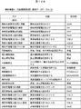
図10は、サーバ9に格納される車両利用計画テーブル1000の一例を示す図である。車両利用計画テーブル1000には、日付1001、利用開始時刻1002、利用終了時刻1003の情報を含む。符号1004、1005、1006、1007は利用計画レコードの例であって、例えばレコード1007は、2012年3月1日の10:00から11:59まで電気自動車5を利用する予定であることを示す。
FIG. 10 is a diagram illustrating an example of the vehicle use plan table 1000 stored in the
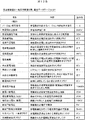
図11は、充放電制御計画テーブル1100の一例を示す図である。制御装置4は、サーバ9から受信した車両利用計画テーブル1000の情報、および電力需要計画や発電計画をもとに充放電制御計画テーブル1100を作成する。充放電制御計画テーブル1100には、開始時刻1101、終了時刻1102、充放電制御種別1103の情報を含む。充放電制御種別1103には、系統電力を使用した充電(1104)、待機状態(1105、1110)、太陽光発電を使用した充電(1106、1108)、電気自動車5に乗車(1107)、電気自動車5から分電装置3への放電(1109)などがある。
FIG. 11 is a diagram illustrating an example of the charge / discharge control plan table 1100. The
図12Aと図12Bは、制御装置4と充放電装置2間の通信データテーブルの例を示す図である。図6、7、8、9のシーケンスにおいて、制御装置4と充放電装置2の間で送受信、通知される情報の一例である。本テーブルに記載した情報を全て送受信してもよいし、特定の情報のみ送受信してもよい。
12A and 12B are diagrams illustrating examples of communication data tables between the
図13Aと図13Bは、充放電装置2と電気自動車5間の通信データテーブルの例を示す図である。図6、7、8、9のシーケンスにおいて、充放電装置2と電気自動車5の間で送受信、通知される情報の一例である。本テーブルに記載した情報を全て送受信してもよいし、特定の情報のみ送受信してもよい。
13A and 13B are diagrams illustrating examples of communication data tables between the charging / discharging
図14は、充放電システムにおける状態遷移を示す図である。
充放電動作では2つの運転状態があり、連系運転状態(S1401)とは、系統電力と接続されて電気自動車5に充放電を行う状態である。一方自立運転状態(S1403)とは、電力系統と切り離されて電気自動車5に充放電を行う状態である。また運転停止状態には、停電停止状態(S1402)と復帰停止状態(S1404)がある。
FIG. 14 is a diagram illustrating state transition in the charge / discharge system.
There are two operation states in the charge / discharge operation, and the interconnection operation state (S1401) is a state in which the
連系運転状態(S1401)で系統電力の停電が発生すると、停電停止状態(S1402)に遷移する。停電停止状態(S1402)でユーザが自立起動を指示すると、自立運転状態(S1403)に遷移する。 When a power failure occurs in the grid power in the interconnected operation state (S1401), the state transits to a power failure stop state (S1402). When the user instructs a self-sustained start in a power outage stop state (S1402), a transition is made to a self-sustained operation state (S1403).
自立運転状態(S1403)で系統電力が復帰すると、復帰停止状態(S1404)に遷移する。復帰停止状態(S1404)でユーザが連系起動を指示すると、連系運転状態(S1401)に遷移する。 When the grid power returns in the self-sustaining operation state (S1403), the state transits to the return stop state (S1404). When the user instructs the start of interconnection in the return stop state (S1404), the state transits to the interconnection operation state (S1401).
その他、停電停止状態(S1402)で系統電力が復帰すると復帰停止状態(S1404)に遷移し、復帰停止状態(S1404)で系統電力の停電が発生すると停電停止状態(S1402)に遷移する。 In addition, when the system power returns in the power outage stop state (S1402), the state transits to the return stop state (S1404), and when the system power outage occurs in the return stop state (S1404), the state transits to the power outage stop state (S1402).
図15は、充放電システムの動作状態ごとの動作機能を示す図である。
(a)連系運転状態(S1401)
充電開始1501:それまでの動作を停止し、電気自動車5へ充電を開始する。
自動制御開始1502:それまでの動作を停止し、制御装置4の充放電制御計画テーブル1100に従い充放電を開始する。
充放電停止1503:充放電を停止し、コネクタロックを解除する。
緊急停止1504:充放電装置2の動作を停止する。
FIG. 15 is a diagram illustrating an operation function for each operation state of the charge / discharge system.
(A) Interconnection operation state (S1401)
Charging start 1501: The operation up to that time is stopped, and charging of the
Automatic control start 1502: The operation up to that point is stopped, and charging / discharging is started according to the charging / discharging control plan table 1100 of the
Charging / discharging stop 1503: The charging / discharging is stopped and the connector lock is released.
Emergency stop 1504: The operation of the charging / discharging
(b)停電停止状態(S1402)
充電開始1511:自立運転を開始し、太陽光発電装置6の電力を用いて電気自動車5に充電する。
緊急停止1512:充放電装置2の動作を停止する。
自動制御開始1513:自立運転を開始し、電気機器8の電力負荷と太陽光発電装置6の発電電力に合わせて、電気自動車5の充電と放電を切換える。
放電1514:自立運転を開始し、電気機器8の電力負荷に合わせて電気自動車5から放電する。
(B) Power outage stop state (S1402)
Charging start 1511: The self-sustained operation is started, and the
Emergency stop 1512: The operation of the charging / discharging
Automatic control start 1513: The self-sustained operation is started, and charging and discharging of the
Discharge 1514: Self-sustained operation is started, and the
(c)自立運転状態(S1403)
充電開始1521:それまでの動作を停止し、太陽光発電電力を用いて電気自動車5に充電する。
充放電停止1522:それまでの動作を停止し、コネクタロックを解除する。
緊急停止1523:充放電装置2の動作を停止する。
自動制御開始1524:それまでの動作を停止し、電気機器8の電力負荷と太陽光発電装置6の発電電力に合わせて、電気自動車5の充電と放電を切換える。
放電1525:それまでの動作を停止し、電気機器8の電力負荷に合わせて電気自動車5から放電する。
(C) Independent operation state (S1403)
Charging start 1521: The operation up to that point is stopped, and the
Charging / discharging stop 1522: The operation so far is stopped and the connector lock is released.
Emergency stop 1523: The operation of the charging / discharging
Automatic control start 1524: The operation up to that point is stopped, and charging and discharging of the
Discharge 1525: The operation so far is stopped, and the
(d)復帰停止状態(S1404)
連系起動1531:連系運転を開始する。
緊急停止1532:充放電装置2の動作を停止する。
(D) Return stop state (S1404)
Interconnection start 1531: The system operation is started.
Emergency stop 1532: The operation of the charging / discharging
なお、図15に示した各動作機能は、例えば制御装置4の表示部45に選択可能な形式で表示してもよく、充放電システム1の動作状態に従い表示する機能を切換えることも可能である。あるいは、ユーザ操作入力部44にボタン等の形式で配置してもよい。
Note that each operation function shown in FIG. 15 may be displayed in a selectable format on the
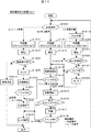
図16は、充放電システムの連系運転における充放電処理フローの一例を示す図である。以下の各フローは制御装置4により進行する。
FIG. 16 is a diagram illustrating an example of a charging / discharging process flow in the interconnected operation of the charging / discharging system. Each of the following flows proceeds by the
S1601:充放電要求種別を判定する。判定の結果、S1602、S1611、S1619に分岐する。 S1601: A charge / discharge request type is determined. As a result of the determination, the process branches to S1602, S1611, and S1619.
S1602:充放電要求種別が(a)「ユーザによる充電指示」である場合、充放電装置2が待機状態に対応しないことを電気自動車5に通知するために、充電器のサスペンドフラグをオフにする。
S1603:S1602で指定した内容で制御装置4、充放電装置2は電気自動車5へ処理開始を通知する。
S1602: When the charge / discharge request type is (a) “charge instruction by user”, the suspend flag of the charger is turned off to notify the
S1603: The
S1604:車両識別は認証済か否かを確認する。未認証であればS1610へ進む。
S1605:車両識別が認証済であれば、ロック部29でコネクタロックする。
S1604: It is confirmed whether or not the vehicle identification has been authenticated. If unauthenticated, the process proceeds to S1610.
S1605: If the vehicle identification has been authenticated, the
S1606:充放電装置2は電気自動車5へ充電を開始する。
S1607:充電中、イベントを監視する。
S1606: The charging / discharging
S1607: An event is monitored during charging.
S1608:電気自動車5の充電量が所定の値(満充電)になったとき、あるいはユーザによる充電(または充放電)停止が指示されると、充電(充放電)を停止する。
S1609:ロック部29でコネクタロックを解除し終了する。
S1608: When the amount of charge of the
S1609: The connector lock is released by the
S1610:車両識別が未認証であれば、表示部45によりユーザに異常を通知し終了する。
S1610: If the vehicle identification is unauthenticated, the
S1611:S1601での充放電要求種別が(b)「電気自動車5からの充放電要求」である場合、充放電装置2が待機状態に対応することを電気自動車5に通知するために、充電器のサスペンドフラグをオンにする。
S1612:S1611で指定した内容で制御装置4、充放電装置2は電気自動車5へ処理開始を通知する。この場合は、充放電装置2と電気自動車5との間の車両識別は完了している。
S1611: When the charge / discharge request type in S1601 is (b) "charge / discharge request from the
S1612: The
S1613:充放電装置2は電気自動車5との間で充放電を開始する。
S1614:充放電中、イベントを監視する。ユーザによる充放電停止が指示された場合、S1608に進み充放電を停止し、S1609でロック解除して終了する。
S1613: The charging / discharging
S1614: An event is monitored during charging / discharging. If the user instructs to stop charging / discharging, the process proceeds to S1608 to stop charging / discharging, and the lock is released in S1609 and the process ends.
S1615:電気自動車5の充電量が所定の値になると、充放電を停止する。なお、所定の値とは電気自動車5の充電量の最大値(満充電)、最小値(電欠)、または制御装置4で作成する充放電制御計画に対応した目標値である。
S1616:電気自動車5が充放電要求を通知するか否かを示す車両サスペンドフラグを確認する。車両サスペンドフラグがオフの場合、S1609に進みコネクタロックを解除し終了する。
S1615: When the charge amount of the
S1616: The vehicle suspend flag indicating whether or not the
S1617:車両サスペンドフラグがオンの場合、充放電装置2は待機状態に入る。
S1618:待機中、イベントを監視する。ユーザによる充放電停止が指示された場合、S1609に進みコネクタロックを解除し終了する。充放電要求が発行されれば、S1601に戻り、本フローを繰り返す。
S1617: When the vehicle suspend flag is on, the charging / discharging
S1618: The event is monitored during standby. If the user has instructed charging / discharging to stop, the process proceeds to S1609, where the connector lock is released and the process ends. If a charge / discharge request is issued, the process returns to S1601 to repeat this flow.
S1619:S1601での充放電要求種別が(c)「自動制御による要求」である場合、充放電制御計画テーブル1100を作成する。
S1620:充放電要求種別が自動制御である場合、待機状態に対応することを電気自動車5に通知するために、充電器のサスペンドフラグをオンにする。
S1619: When the charge / discharge request type in S1601 is (c) “request by automatic control”, the charge / discharge control plan table 1100 is created.
S1620: When the charge / discharge request type is automatic control, the suspend flag of the charger is turned on to notify the
S1621:S1620で指定した内容で制御装置4、充放電装置2は電気自動車5へ処理開始を通知する。
S1622:車両識別は認証済か否かを確認する。未認証であればS1610へ進み、ユーザに異常を通知し終了する。
S1621: The
S1622: It is confirmed whether or not the vehicle identification has been authenticated. If unauthenticated, the process advances to step S1610 to notify the user of the abnormality and the process ends.
S1623:車両識別が認証済であれば、コネクタロック済か否かを確認する。ロック済であればS1613へ進み、充放電制御計画に従い充放電装置2は電気自動車5との間で充放電を開始する。
S1624:コネクタが未ロックであれば、ロック部29でコネクタロックする。そしてS1613へ進み、充放電制御計画に従い充放電を開始する。
S1623: If the vehicle identification has been authenticated, it is confirmed whether or not the connector has been locked. If locked, the process proceeds to S1613, and the charging / discharging
S1624: If the connector is not locked, the connector is locked by the
このように連系運転時の充放電制御では、充放電要求種別を判定するステップ(S1601)と、判定した充放電要求種別に応じて、充放電装置と電気自動車とのコネクタをロックしたままとする待機状態に対応させるか否かを設定するステップ(S1602、S1611、S1620)と、電気自動車に対し要求された充放電を実行するステップ(S1606、S1613)と、充放電を終了したとき、電気自動車から充放電装置に対し待機状態の要求があるか否かを確認するステップ(S1616)と、電気自動車から待機状態の要求がある場合は待機状態に移行し(S1617)、電気自動車から待機状態の要求がない場合はコネクタのロックを解除するステップ(S1609)と、を備えることに特徴がある。 In this way, in the charge / discharge control during the grid operation, the step of determining the charge / discharge request type (S1601) and the connector between the charge / discharge device and the electric vehicle are locked according to the determined charge / discharge request type. Step (S1602, S1611, S1620) for setting whether to correspond to the standby state to be performed, steps (S1606, S1613) for performing charge / discharge requested to the electric vehicle, A step of confirming whether or not there is a standby state request from the vehicle to the charging / discharging device (S1616), and if there is a standby state request from the electric vehicle, transitions to a standby state (S1617) and the standby state from the electric vehicle. A step (S1609) for releasing the lock of the connector when there is no request.
このように、待機状態に対応するか否かを設定することで、次の充放電動作を開始する際にコネクタロックを行うステップを最小限に抑え、動作の切替をスムーズに移行することができる。 In this way, by setting whether or not to correspond to the standby state, it is possible to minimize the step of locking the connector when starting the next charge / discharge operation, and to smoothly switch the operation. .
図17は、充放電システムの自立運転における充放電処理フローの一例を示す図である。以下の各フローは制御装置4により進行される。
FIG. 17 is a diagram illustrating an example of a charge / discharge process flow in the self-sustaining operation of the charge / discharge system. The following flows are advanced by the
S1701:自立運転においては待機状態に対応しないことを電気自動車5に通知するために、充電器のサスペンドフラグをオフにする。
S1702:S1701で指定した内容で制御装置4、充放電装置2は電気自動車5へ処理開始を通知する。
S1701: In order to notify the
S1702: The
S1703:車両識別は認証済か否かを確認する。未認証であればS1712へ進む。
S1704:車両識別が認証済であれば、ロック部29でコネクタロックする。
S1703: It is confirmed whether or not the vehicle identification has been authenticated. If unauthenticated, the process advances to step S1712.
S1704: If the vehicle identification has been authenticated, the
S1705:充放電要求種別を判定する。判定の結果、S1706、S1707、S1708に分岐する。
S1706:充放電要求種別が(a)「充電」であれば、太陽光発電装置6の発電電力を用いて電気自動車5への充電を開始する。
S1707:充放電要求種別が(b)「放電」であれば、電気機器8の電力負荷に合わせて電気自動車5から放電を開始する。
S1708:充放電要求種別が(c)「自動制御」であれば、電気機器8の電力負荷と太陽光発電装置6の発電電力に応じて、電気自動車5に対する充電と放電を切換える。
S1705: The charge / discharge request type is determined. As a result of the determination, the process branches to S1706, S1707, and S1708.
S 1706: If the charge / discharge request type is (a) “charge”, charging of the
S1707: If the charge / discharge request type is (b) “discharge”, the
S1708: If the charge / discharge request type is (c) "automatic control", charging and discharging of the
S1709:充放電中、イベントを監視する。
S1710:電気自動車5の充電量が所定の値になる、あるいはユーザによる充放電停止が指示されると、充放電を停止する。なお、所定の値とは電気自動車5の充電量の最大値(満充電)、最小値(電欠)、または制御装置4で作成する充放電制御計画に対応した目標値である。
S1711:ロック部29でコネクタロックを解除し終了する。
S1709: An event is monitored during charging / discharging.
S1710: When the charge amount of the
S1711: The connector lock is released by the
S1712:車両識別が未認証であれば、表示部45等を用いてユーザに充放電を許可するか否か確認を促す。ユーザが充放電を許可した場合はS1704に進み、許可しない場合は終了する。
S1712: If the vehicle identification is unauthenticated, the
このように自立運転時の充放電制御によれば、系統電力に停電が発生した場合、充放電制御計画による充放電動作を停止し、ユーザからの指示により、太陽光発電装置から電気自動車に充電し(S1706)、あるいは電気自動車から放電させて電気機器に供給し(S1707)、あるいは電気機器の電力負荷と太陽光発電装置の発電電力に応じて、電気自動車に対する充電と放電を切換える(S1708)ことを特徴とする。 As described above, according to the charge / discharge control during the independent operation, when a power failure occurs in the system power, the charge / discharge operation according to the charge / discharge control plan is stopped, and the electric vehicle is charged from the solar power generation device according to the instruction from the user. (S1706), or the electric vehicle is discharged and supplied to the electric device (S1707), or charging and discharging of the electric vehicle are switched according to the electric load of the electric device and the generated power of the solar power generation device (S1708). It is characterized by that.
これより、系統電力に停電が発生した場合であっても、太陽光発電装置と電気自動車と電気機器との間で、効率良く電力の供給を行うことができる。 Thus, even when a power failure occurs in the system power, it is possible to efficiently supply power between the solar power generation device, the electric vehicle, and the electric device.
なお、本発明は上記した実施例に限定されるものではなく、様々な変形例が含まれる。例えば、上記した実施例は本発明を分かりやすく説明するために詳細に説明したものであり、必ずしも説明した全ての構成を備えるものに限定されるものではない。また、ある実施例の構成の一部を他の実施例の構成に置き換えることが可能であり、また、ある実施例の構成に他の実施例の構成を加えることも可能である。また、各実施例の構成の一部について、他の構成の追加・削除・置換をすることが可能である。 In addition, this invention is not limited to an above-described Example, Various modifications are included. For example, the above-described embodiments have been described in detail for easy understanding of the present invention, and are not necessarily limited to those having all the configurations described. Further, a part of the configuration of one embodiment can be replaced with the configuration of another embodiment, and the configuration of another embodiment can be added to the configuration of one embodiment. Further, it is possible to add, delete, and replace other configurations for a part of the configuration of each embodiment.
また、上記の各構成、機能、処理部、処理手段等は、それらの一部又は全部を、例えば集積回路で設計する等によりハードウェアで実現してもよい。また、上記の各構成、機能等は、プロセッサがそれぞれの機能を実現するプログラムを解釈し、実行することによりソフトウェアで実現してもよい。各機能を実現するプログラム、テーブル、ファイル等の情報は、メモリや、ハードディスク、SSD(Solid State Drive)等の記録装置、または、ICカード、SDカード、DVD等の記録媒体に置くことができる。 Each of the above-described configurations, functions, processing units, processing means, and the like may be realized by hardware by designing a part or all of them with, for example, an integrated circuit. Each of the above-described configurations, functions, and the like may be realized by software by interpreting and executing a program that realizes each function by the processor. Information such as programs, tables, and files for realizing each function can be stored in a memory, a hard disk, a recording device such as an SSD (Solid State Drive), or a recording medium such as an IC card, an SD card, or a DVD.
また、電力線や通信線は説明上必要と考えられるものを示しており、製品では必ずしも全ての電力線や通信線を備えるとは限らない。実際には殆ど全ての構成が相互に接続されていると考えてもよい。 Moreover, the power line and the communication line are those that are considered necessary for the explanation, and the product does not necessarily include all the power lines and communication lines. Actually, it may be considered that almost all the components are connected to each other.
1:充放電システム、
2:充放電装置、
3:分電装置、
4:制御装置、
5:電気自動車、
6:太陽光発電装置、
7:電池、
8:電気機器、
9:サーバ、
10:ネットワーク、
20:太陽光発電電力入力部、
21:系統電力入出力部、
22:自動車電力入出力部、
23a:DC−DC電力変換部、
23b:AC−DC電力変換部、
23c:DC−DC電力変換部、
24:分電装置通信部、
25:制御部、
26:自動車通信部、
27:制御装置通信部、
28:電池電力入力部、
29:ロック部、
30:系統電力入力部、
31:主幹ブレーカ、
32:第1のブレーカ、
33:第1の電力出力部、
34:第2のブレーカ、
35:第2の電力出力部、
36:充放電装置電力入出力部、
37:監視部、
38:充放電装置通信部、
40:充放電装置通信部、
41:ネットワーク通信部、
42:制御部、
43:記憶部、
44:ユーザ操作入力部、
45:表示部、
46:電池、
50:充放電装置通信部、
51:制御部、
52:ユーザ操作部、
53:充放電装置電力入出力部、
54:電池監視部、
55:電池、
56:モータ、
57:駆動部。
1: charge / discharge system,
2: Charge / discharge device,
3: Power distribution device,
4: Control device,
5: Electric car,
6: Solar power generator,
7: Battery,
8: Electrical equipment,
9: Server,
10: Network,
20: Photovoltaic power input section,
21: System power input / output unit,
22: Automotive power input / output unit,
23a: DC-DC power converter,
23b: AC-DC power converter,
23c: DC-DC power converter,
24: Distribution device communication unit,
25: Control unit,
26: Automotive communication department
27: Control device communication unit,
28: Battery power input unit,
29: Lock part,
30: System power input unit,
31: Master breaker,
32: First breaker,
33: a first power output unit,
34: Second breaker,
35: second power output unit,
36: Charge / discharge device power input / output unit,
37: Monitoring unit,
38: Charging / discharging device communication unit,
40: Charging / discharging device communication unit,
41: Network communication unit,
42: control unit,
43: Storage unit
44: User operation input unit,
45: Display unit,
46: battery
50: Charge / discharge device communication unit,
51: Control unit,
52: User operation unit,
53: Charge / discharge device power input / output unit,
54: Battery monitoring unit,
55: Battery,
56: motor,
57: Drive unit.
Claims (2)
前記電力供給源と前記電気自動車に接続され、前記電気自動車に対し充放電を行う充放電装置と、
前記充放電装置の充放電動作を制御する制御装置と、を有し、
前記電力供給源として、系統電力が入力される分電装置と太陽光発電装置と、を備え、
前記充放電装置は、前記制御装置の制御により電気機器の電力負荷に合わせて前記電気自動車からの放電電力を調整しながら、前記電気自動車から放電された電力を前記分電装置を介して前記電気機器に供給し、
前記制御装置は、前記電気自動車からの放電電力と前記太陽光発電装置による発電電力の総和が前記分電装置に接続された前記電気機器の電力消費よりも大きくなった場合に、前記放電電力を抑えて前記系統電力へ前記放電電力が出力されないように制御し、
前記制御装置は、前記充放電装置を介して前記制御装置に送信された前記電気自動車の現在の充電量が所定の値に到達したときに充放電動作を停止させると共に、
更に、前記制御装置は、ネットワークを介して接続されたサーバから前記電気自動車の利用計画情報を入手し、入手した前記利用計画情報に基づいた充放電制御情報を前記充放電装置に送って前記電気自動車への充放電動作を制御する
ことを特徴とする充放電システム。 In the charge / discharge system for charging the electric vehicle from an electric power supply source and discharging the electric power charged in the electric vehicle,
A charging / discharging device connected to the power supply source and the electric vehicle for charging / discharging the electric vehicle;
A control device for controlling the charge / discharge operation of the charge / discharge device,
As the power supply source, comprising a power distribution device and a photovoltaic power generation device to which system power is input,
The charging / discharging device controls the electric power discharged from the electric vehicle through the power distribution device while adjusting the electric power discharged from the electric vehicle according to the electric power load of the electric device under the control of the control device. Supply to the equipment,
Wherein the control device, when the sum of electric power generated by the discharge power and the photovoltaic device from the electric vehicle is larger than the power consumption of the electrical device connected to the power distribution device, the discharge power suppressed and the discharge power is controlled so as not to be output to the power grid,
The control device stops the charge / discharge operation when the current charge amount of the electric vehicle transmitted to the control device via the charge / discharge device reaches a predetermined value,
Further, the control device obtains usage plan information of the electric vehicle from a server connected via a network, and sends charge / discharge control information based on the obtained usage plan information to the charge / discharge device. A charge / discharge system for controlling a charge / discharge operation for an automobile.
系統電力を入出力する系統電力入出力部と、
太陽光発電電力を入力する太陽光発電電力入力部と、
前記電気自動車との間で電力を入出力する電気自動車電力入出力部と、
制御装置からの充放電指示により電力の入出力を制御する制御部と、を備え、
前記充放電装置は、前記制御部の制御により電気機器の電力負荷に合わせて前記電気自動車からの放電電力を調整しながら、前記電気自動車から放電された電力を分電装置を介して前記電気機器に供給し、
前記制御部は、前記電気自動車からの放電電力と太陽光発電装置による発電電力の総和が前記分電装置に接続された前記電気機器の電力消費よりも大きくなった場合に、前記放電電力を抑えて前記系統電力へ前記放電電力が出力されないように制御すると共に、
更に、前記制御部は、ネットワークを介して接続されたサーバから前記電気自動車の利用計画情報を入手した前記制御装置から送られてくる前記利用計画情報に基づいた充放電制御情報にしたがって前記電気自動車への充放電動作を制御する
ことを特徴とする充放電装置。 In a charging / discharging device that is connected to an electric power supply source and an electric vehicle, and charges and discharges the electric vehicle
A grid power input / output unit that inputs and outputs grid power;
A photovoltaic power input section for inputting photovoltaic power,
An electric vehicle power input / output unit for inputting / outputting electric power to / from the electric vehicle;
A control unit that controls input / output of electric power according to a charge / discharge instruction from the control device,
The charging / discharging device controls the electric power discharged from the electric vehicle via the power distribution device while adjusting the discharging power from the electric vehicle according to the electric power load of the electric device under the control of the control unit. To supply
The control unit suppresses the discharge power when the sum of the discharge power from the electric vehicle and the power generated by the solar power generation device is larger than the power consumption of the electric device connected to the power distribution device. And controlling so that the discharge power is not output to the grid power,
Further, the control unit includes the electric vehicle according to charge / discharge control information based on the use plan information sent from the control device that has obtained use plan information of the electric vehicle from a server connected via a network. The charging / discharging apparatus characterized by controlling the charging / discharging operation | movement to.
Priority Applications (1)
| Application Number | Priority Date | Filing Date | Title |
|---|---|---|---|
| JP2012195220A JP6280687B2 (en) | 2012-09-05 | 2012-09-05 | Charging / discharging system and charging / discharging device |
Applications Claiming Priority (1)
| Application Number | Priority Date | Filing Date | Title |
|---|---|---|---|
| JP2012195220A JP6280687B2 (en) | 2012-09-05 | 2012-09-05 | Charging / discharging system and charging / discharging device |
Publications (2)
| Publication Number | Publication Date |
|---|---|
| JP2014054010A JP2014054010A (en) | 2014-03-20 |
| JP6280687B2 true JP6280687B2 (en) | 2018-02-14 |
Family
ID=50611977
Family Applications (1)
| Application Number | Title | Priority Date | Filing Date |
|---|---|---|---|
| JP2012195220A Active JP6280687B2 (en) | 2012-09-05 | 2012-09-05 | Charging / discharging system and charging / discharging device |
Country Status (1)
| Country | Link |
|---|---|
| JP (1) | JP6280687B2 (en) |
Families Citing this family (5)
| Publication number | Priority date | Publication date | Assignee | Title |
|---|---|---|---|---|
| JP2017099137A (en) * | 2015-11-24 | 2017-06-01 | 三菱電機株式会社 | Power Conditioner |
| JP6504101B2 (en) * | 2016-04-15 | 2019-04-24 | 株式会社椿本チエイン | Power controller |
| JP7104473B2 (en) * | 2017-10-31 | 2022-07-21 | シャープ株式会社 | Energy management system, power conversion control device, and power conversion control method |
| JP2019170025A (en) * | 2018-03-22 | 2019-10-03 | 株式会社椿本チエイン | Charge and discharge device and server |
| CN109986987A (en) * | 2019-05-07 | 2019-07-09 | 吉林大学青岛汽车研究院 | A kind of electric car based on solar energy and electric energy shares charging system and its charging method |
Family Cites Families (6)
| Publication number | Priority date | Publication date | Assignee | Title |
|---|---|---|---|---|
| JP3985390B2 (en) * | 1999-06-17 | 2007-10-03 | 日産自動車株式会社 | Power management system |
| JP2007252118A (en) * | 2006-03-16 | 2007-09-27 | Chugoku Electric Power Co Inc:The | Power supplying facility and power supplying method |
| JP2010273407A (en) * | 2009-05-19 | 2010-12-02 | Osaka Gas Co Ltd | Energy supply system |
| JP2011217590A (en) * | 2010-03-18 | 2011-10-27 | Sanyo Electric Co Ltd | Air conditioning system |
| JP5782233B2 (en) * | 2010-06-14 | 2015-09-24 | 大和ハウス工業株式会社 | Energy management system and energy management method |
| EP2662949A4 (en) * | 2011-01-06 | 2017-04-19 | Nec Corporation | Charging control device, charging control method, and program |
-
2012
- 2012-09-05 JP JP2012195220A patent/JP6280687B2/en active Active
Also Published As
| Publication number | Publication date |
|---|---|
| JP2014054010A (en) | 2014-03-20 |
Similar Documents
| Publication | Publication Date | Title |
|---|---|---|
| JP6280687B2 (en) | Charging / discharging system and charging / discharging device | |
| CA2761022C (en) | Uninterruptible power supply system | |
| EP3376636B1 (en) | Power supplying device and method | |
| US9537341B2 (en) | Power supply output configuration system and method | |
| JP6956384B2 (en) | Charge control system, power supply system, charge control method, program | |
| CN104272573A (en) | A modular three-phase online UPS | |
| WO2016121273A1 (en) | Power control device, power control method, and power control system | |
| KR101344931B1 (en) | Built-type charging system | |
| JP2014079139A (en) | Dc feed system and electric apparatus | |
| JP5895165B2 (en) | Power converter | |
| EP2701293A2 (en) | Improved dual-input power supply | |
| WO2018212135A1 (en) | Controller, electricity storage system, and program | |
| JP6895604B2 (en) | Power conversion system | |
| CN114977351A (en) | Energy storage system and black start method | |
| US20140252854A1 (en) | Real time power monitor and management system | |
| JP2015523045A (en) | Battery for supplying voltage to the power module | |
| CN103368198A (en) | System and method for controlling solar power conversion systems | |
| JPWO2017145338A1 (en) | Power converter | |
| EP4270727A1 (en) | Reversed power and grid support with a modular approach | |
| JP5012741B2 (en) | Power supply device, power supply method, power supply control program, and power supply system | |
| JP2015023604A (en) | Power supply system, power supply method, and conversion device for load | |
| CN215419598U (en) | Power supply system | |
| JP2018133905A (en) | Electric power conversion system | |
| EP4350943A1 (en) | Operating with secondary power sources | |
| CN117639149A (en) | Charging system and charger thereof |
Legal Events
| Date | Code | Title | Description |
|---|---|---|---|
| A621 | Written request for application examination |
Free format text: JAPANESE INTERMEDIATE CODE: A621 Effective date: 20150306 |
|
| A977 | Report on retrieval |
Free format text: JAPANESE INTERMEDIATE CODE: A971007 Effective date: 20151228 |
|
| A131 | Notification of reasons for refusal |
Free format text: JAPANESE INTERMEDIATE CODE: A131 Effective date: 20160126 |
|
| A521 | Written amendment |
Free format text: JAPANESE INTERMEDIATE CODE: A523 Effective date: 20160325 |
|
| A131 | Notification of reasons for refusal |
Free format text: JAPANESE INTERMEDIATE CODE: A131 Effective date: 20160628 |
|
| A521 | Written amendment |
Free format text: JAPANESE INTERMEDIATE CODE: A523 Effective date: 20160824 |
|
| A02 | Decision of refusal |
Free format text: JAPANESE INTERMEDIATE CODE: A02 Effective date: 20170124 |
|
| A521 | Written amendment |
Free format text: JAPANESE INTERMEDIATE CODE: A523 Effective date: 20170321 |
|
| A521 | Written amendment |
Free format text: JAPANESE INTERMEDIATE CODE: A821 Effective date: 20170322 |
|
| A911 | Transfer of reconsideration by examiner before appeal (zenchi) |
Free format text: JAPANESE INTERMEDIATE CODE: A911 Effective date: 20170417 |
|
| A912 | Removal of reconsideration by examiner before appeal (zenchi) |
Free format text: JAPANESE INTERMEDIATE CODE: A912 Effective date: 20170526 |
|
| A521 | Written amendment |
Free format text: JAPANESE INTERMEDIATE CODE: A523 Effective date: 20171102 |
|
| A61 | First payment of annual fees (during grant procedure) |
Free format text: JAPANESE INTERMEDIATE CODE: A61 Effective date: 20180122 |
|
| R150 | Certificate of patent or registration of utility model |
Ref document number: 6280687 Country of ref document: JP Free format text: JAPANESE INTERMEDIATE CODE: R150 |