EP4557352A1 - Coating apparatus and coating method - Google Patents
Coating apparatus and coating method Download PDFInfo
- Publication number
- EP4557352A1 EP4557352A1 EP23926302.3A EP23926302A EP4557352A1 EP 4557352 A1 EP4557352 A1 EP 4557352A1 EP 23926302 A EP23926302 A EP 23926302A EP 4557352 A1 EP4557352 A1 EP 4557352A1
- Authority
- EP
- European Patent Office
- Prior art keywords
- coating
- bar
- base material
- nozzle
- leveling
- Prior art date
- Legal status (The legal status is an assumption and is not a legal conclusion. Google has not performed a legal analysis and makes no representation as to the accuracy of the status listed.)
- Pending
Links
Images

Classifications
-
- B—PERFORMING OPERATIONS; TRANSPORTING
- B05—SPRAYING OR ATOMISING IN GENERAL; APPLYING FLUENT MATERIALS TO SURFACES, IN GENERAL
- B05C—APPARATUS FOR APPLYING FLUENT MATERIALS TO SURFACES, IN GENERAL
- B05C11/00—Component parts, details or accessories not specifically provided for in groups B05C1/00 - B05C9/00
- B05C11/02—Apparatus for spreading or distributing liquids or other fluent materials already applied to a surface ; Controlling means therefor; Control of the thickness of a coating by spreading or distributing liquids or other fluent materials already applied to the coated surface
- B05C11/023—Apparatus for spreading or distributing liquids or other fluent materials already applied to a surface
- B05C11/025—Apparatus for spreading or distributing liquids or other fluent materials already applied to a surface with an essentially cylindrical body, e.g. roll or rod
-
- H—ELECTRICITY
- H10—SEMICONDUCTOR DEVICES; ELECTRIC SOLID-STATE DEVICES NOT OTHERWISE PROVIDED FOR
- H10P—GENERIC PROCESSES OR APPARATUS FOR THE MANUFACTURE OR TREATMENT OF DEVICES COVERED BY CLASS H10
- H10P72/00—Handling or holding of wafers, substrates or devices during manufacture or treatment thereof
- H10P72/04—Apparatus for manufacture or treatment
- H10P72/0448—Apparatus for applying a liquid, a resin, an ink or the like
-
- B—PERFORMING OPERATIONS; TRANSPORTING
- B05—SPRAYING OR ATOMISING IN GENERAL; APPLYING FLUENT MATERIALS TO SURFACES, IN GENERAL
- B05C—APPARATUS FOR APPLYING FLUENT MATERIALS TO SURFACES, IN GENERAL
- B05C1/00—Apparatus in which liquid or other fluent material is applied to the surface of the work by contact with a member carrying the liquid or other fluent material, e.g. a porous member loaded with a liquid to be applied as a coating
- B05C1/04—Apparatus in which liquid or other fluent material is applied to the surface of the work by contact with a member carrying the liquid or other fluent material, e.g. a porous member loaded with a liquid to be applied as a coating for applying liquid or other fluent material to work of indefinite length
-
- B—PERFORMING OPERATIONS; TRANSPORTING
- B05—SPRAYING OR ATOMISING IN GENERAL; APPLYING FLUENT MATERIALS TO SURFACES, IN GENERAL
- B05C—APPARATUS FOR APPLYING FLUENT MATERIALS TO SURFACES, IN GENERAL
- B05C1/00—Apparatus in which liquid or other fluent material is applied to the surface of the work by contact with a member carrying the liquid or other fluent material, e.g. a porous member loaded with a liquid to be applied as a coating
- B05C1/04—Apparatus in which liquid or other fluent material is applied to the surface of the work by contact with a member carrying the liquid or other fluent material, e.g. a porous member loaded with a liquid to be applied as a coating for applying liquid or other fluent material to work of indefinite length
- B05C1/08—Apparatus in which liquid or other fluent material is applied to the surface of the work by contact with a member carrying the liquid or other fluent material, e.g. a porous member loaded with a liquid to be applied as a coating for applying liquid or other fluent material to work of indefinite length using a roller or other rotating member which contacts the work along a generating line
- B05C1/0804—Apparatus in which liquid or other fluent material is applied to the surface of the work by contact with a member carrying the liquid or other fluent material, e.g. a porous member loaded with a liquid to be applied as a coating for applying liquid or other fluent material to work of indefinite length using a roller or other rotating member which contacts the work along a generating line the material being applied without contact with the roller
-
- B—PERFORMING OPERATIONS; TRANSPORTING
- B05—SPRAYING OR ATOMISING IN GENERAL; APPLYING FLUENT MATERIALS TO SURFACES, IN GENERAL
- B05C—APPARATUS FOR APPLYING FLUENT MATERIALS TO SURFACES, IN GENERAL
- B05C1/00—Apparatus in which liquid or other fluent material is applied to the surface of the work by contact with a member carrying the liquid or other fluent material, e.g. a porous member loaded with a liquid to be applied as a coating
- B05C1/04—Apparatus in which liquid or other fluent material is applied to the surface of the work by contact with a member carrying the liquid or other fluent material, e.g. a porous member loaded with a liquid to be applied as a coating for applying liquid or other fluent material to work of indefinite length
- B05C1/08—Apparatus in which liquid or other fluent material is applied to the surface of the work by contact with a member carrying the liquid or other fluent material, e.g. a porous member loaded with a liquid to be applied as a coating for applying liquid or other fluent material to work of indefinite length using a roller or other rotating member which contacts the work along a generating line
- B05C1/0826—Apparatus in which liquid or other fluent material is applied to the surface of the work by contact with a member carrying the liquid or other fluent material, e.g. a porous member loaded with a liquid to be applied as a coating for applying liquid or other fluent material to work of indefinite length using a roller or other rotating member which contacts the work along a generating line the work being a web or sheets
-
- B—PERFORMING OPERATIONS; TRANSPORTING
- B05—SPRAYING OR ATOMISING IN GENERAL; APPLYING FLUENT MATERIALS TO SURFACES, IN GENERAL
- B05C—APPARATUS FOR APPLYING FLUENT MATERIALS TO SURFACES, IN GENERAL
- B05C1/00—Apparatus in which liquid or other fluent material is applied to the surface of the work by contact with a member carrying the liquid or other fluent material, e.g. a porous member loaded with a liquid to be applied as a coating
- B05C1/04—Apparatus in which liquid or other fluent material is applied to the surface of the work by contact with a member carrying the liquid or other fluent material, e.g. a porous member loaded with a liquid to be applied as a coating for applying liquid or other fluent material to work of indefinite length
- B05C1/08—Apparatus in which liquid or other fluent material is applied to the surface of the work by contact with a member carrying the liquid or other fluent material, e.g. a porous member loaded with a liquid to be applied as a coating for applying liquid or other fluent material to work of indefinite length using a roller or other rotating member which contacts the work along a generating line
- B05C1/0873—Controlling means responsive to conditions of the liquid or other fluent material, of the ambient medium, of the roller or of the work
-
- B—PERFORMING OPERATIONS; TRANSPORTING
- B05—SPRAYING OR ATOMISING IN GENERAL; APPLYING FLUENT MATERIALS TO SURFACES, IN GENERAL
- B05D—PROCESSES FOR APPLYING FLUENT MATERIALS TO SURFACES, IN GENERAL
- B05D1/00—Processes for applying liquids or other fluent materials
- B05D1/26—Processes for applying liquids or other fluent materials performed by applying the liquid or other fluent material from an outlet device in contact with, or almost in contact with, the surface
-
- B—PERFORMING OPERATIONS; TRANSPORTING
- B05—SPRAYING OR ATOMISING IN GENERAL; APPLYING FLUENT MATERIALS TO SURFACES, IN GENERAL
- B05D—PROCESSES FOR APPLYING FLUENT MATERIALS TO SURFACES, IN GENERAL
- B05D1/00—Processes for applying liquids or other fluent materials
- B05D1/40—Distributing applied liquids or other fluent materials by members moving relatively to surface
- B05D1/42—Distributing applied liquids or other fluent materials by members moving relatively to surface by non-rotary members
-
- H—ELECTRICITY
- H10—SEMICONDUCTOR DEVICES; ELECTRIC SOLID-STATE DEVICES NOT OTHERWISE PROVIDED FOR
- H10K—ORGANIC ELECTRIC SOLID-STATE DEVICES
- H10K30/00—Organic devices sensitive to infrared radiation, light, electromagnetic radiation of shorter wavelength or corpuscular radiation
- H10K30/50—Photovoltaic [PV] devices
-
- H—ELECTRICITY
- H10—SEMICONDUCTOR DEVICES; ELECTRIC SOLID-STATE DEVICES NOT OTHERWISE PROVIDED FOR
- H10K—ORGANIC ELECTRIC SOLID-STATE DEVICES
- H10K71/00—Manufacture or treatment specially adapted for the organic devices covered by this subclass
- H10K71/10—Deposition of organic active material
- H10K71/12—Deposition of organic active material using liquid deposition, e.g. spin coating
-
- B—PERFORMING OPERATIONS; TRANSPORTING
- B05—SPRAYING OR ATOMISING IN GENERAL; APPLYING FLUENT MATERIALS TO SURFACES, IN GENERAL
- B05D—PROCESSES FOR APPLYING FLUENT MATERIALS TO SURFACES, IN GENERAL
- B05D2252/00—Sheets
- B05D2252/02—Sheets of indefinite length
Definitions
- Embodiments of the present invention relate to a coating device and a coating method that can be used for device formation.
- Organic thin-film solar cells using an organic semiconductor and organic/inorganic hybrid solar cells are expected as low-cost solar cells because an inexpensive coating method can be applied to form an active layer.
- it is required to uniformly apply a coating material for forming an organic active layer and other layers.
- the thickness of each layer is about several nm to several 100 nm, and it is required to form such a very thin layer with a large area and high uniformity.
- a meniscus coating method or a slit coating method is known as a roll-to-roll (R2R) coating method capable of forming an extremely thin layer over a large area at low cost.
- R2R roll-to-roll
- Patent Literature 1 JP 2003-251256 A
- Embodiments of the present invention provide a coating device and a coating method capable of forming a uniform coating film.
- Fig. 1 is a schematic side view illustrating a coating device according to a first embodiment.
- Fig. 2 is a schematic top view illustrating the coating device according to the first embodiment.
- a coating device 100 includes a coating bar 101, a base material conveyance member 102 that conveys a base material, a coating liquid supply member 104 that supplies a coating liquid 103 stored in a liquid reservoir 112 to the coating bar, and a leveling bar 105.
- the leveling bar 105 is arranged at a position where the coating liquid forms a meniscus between the leveling bar and the base material. Then, in this example, a primary coating film is formed by a so-called meniscus method using the coating bar.
- Each member is arranged such that the coating liquid 103 is supplied from a nozzle 106 to a surface of the coating bar 101, the coating liquid flows from the surface of the coating bar to between the coating bar 101 and a base material 107 to form a meniscus 103Ma, and the base material is conveyed in an arrow direction to form a primary coating film 108a.
- a cross-sectional shape of the coating bar 101 is arbitrary.
- the cross-sectional shape is, for example, a circular shape, a flat circular shape, or a polygonal shape.
- a portion of the cross-sectional shape that corresponds to a meniscus forming portion may be curved, and the other portion may be linear.
- a cross-sectional shape of a surface of the coating bar 101 that faces the base material 107 may be curved.
- the coating bar can be arranged so as not to rotate. As the coating bar does not rotate like a roller, stability of the meniscus is improved.
- the coating bar 101 contains, for example, at least one selected from the group consisting of stainless steel, aluminum, titanium, and glass. Therefore, processing is facilitated when preparing the coating bar 101.
- the surface of the coating bar 101 is a mirror surface. In another example, the surface of the coating bar 101 may have an uneven structure.
- the leveling bar 105 is installed at a position downstream of the coating bar 101 in a coating direction.
- the coating bar 101 applies the coating liquid 103 to almost the entire surface of the base material 107 to form the coating film 108a, but uniformity of the coating film 108a may be insufficient.
- the coating film 108a formed in the present embodiment comes into contact with the leveling bar 105 arranged at a position downstream of the coating bar as the base material is conveyed.
- the meniscus 103Mb of the coating liquid 103 can be formed between the base material 107 and the leveling bar 105.
- the uniform meniscus 103Mb is formed by a surface tension of the coating liquid.
- a secondary coating film 108b having high uniformity and formed by the coating 103 is formed on the base material 107.
- An intended film is obtained by solidifying the coating film 108b by, for example, drying.
- a drying member 109 can be arranged at a position downstream of the leveling bar.
- the coating film 108b having a large area can be formed on the base material 107, for example, by moving the base material 107 in a movement direction (an arrow direction in the drawing).
- the coating device illustrated in Figs. 1 and 2 forms the primary coating film by the meniscus method, and the coating device may further include a nozzle position adjustment member 110 that adjusts a position of the nozzle 106, a nozzle position detection member 111 that detects a distance between the coating bar 101 and the nozzle 106, and the like in order to improve the uniformity of the primary coating film.
- a plurality of nozzles 106 or a plurality of pumps 104 can be used as illustrated in Fig. 2 .
- the plurality of nozzles 106 can face the coating bar 101.
- the plurality of nozzles 106 can supply the coating liquid 103 toward the coating bar 101.
- an additional nozzle for supplying the coating liquid to the leveling bar 105 may be further provided. It is possible to form a meniscus between the base material and the leveling bar before forming the primary coating film before the coating is started by arranging such an additional nozzle.
- the plurality of nozzles 106 are arranged in a first direction.
- the first direction is, for example, a Y-axis direction.
- One direction perpendicular to the Y-axis direction is defined as an X-axis direction.
- the movement direction of the base material can coincide with an X axis.
- a direction perpendicular to the Y-axis direction and the X-axis direction is defined as a Z-axis direction.
- the coating bar 101 extends, for example, in the Y-axis direction.
- the number of plurality of nozzles 106 may be three or more. As a result, the primary coating film 108a having a large area can be stably formed. In the example of Fig. 2 , the number of plurality of nozzles 106 is four. In the embodiment, the number may be an arbitrary integer of 3 or more.
- the nozzle can be a slot die or can have a needle shape.
- a discharge amount of the coating liquid 103 can be controlled with high accuracy by using the plurality of needle-shaped nozzles 106.
- the needle-shaped nozzle has high flexibility. Due to the high flexibility, for example, damage to the nozzle due to vibration of the coating bar 101 or the like can be suppressed.
- a length of the nozzle is, for example, 10 mm or more and 100 mm or less, and an inner diameter of the nozzle is, for example, 0.5 mm or more and 2 mm or less.
- An angle between an end surface of the tip of the nozzle and an extending direction of the nozzle is, for example, about 90 degrees (for example, 75 degrees or more and 105 degrees or less). With such a shape, for example, occurrence of scratches on the coating bar 101 can be suppressed.
- a distance between the coating bar 101 and the tip of each nozzle tends to vary.
- the meniscus 103Ma formed from each nozzle is likely to be disturbed, and as a result, the coating film 108a is likely to be non-uniform.
- nozzle position adjustment member 110 that adjusts the position of each nozzle and the nozzle position detection member 111 that detects a distance between the coating bar 101 and each nozzle 106 are provided as illustrated in Figs. 1 and 2 , it is possible to reduce variation in the position and the distance between the tip of each nozzle and the coating bar, and to achieve uniform coating.
- a member that detects contact between the coating bar and each nozzle can be further provided.
- the contact is easily detected by, for example, a method of measuring an electric resistance between the nozzle and the coating bar, and thus, the variation can be reduced by adjusting a coating condition based on the contact.
- the coating liquid can be directly applied to the coating bar, and repelling of the coating liquid hardly occurs.
- a member that measures the electric resistance between each nozzle and the coating bar can be provided as the member that detects the contact between the coating bar and each nozzle. If each nozzle and the coating bar are made of conductive stainless steel or the like, and the nozzles are insulated from each other, when the electric resistance between the coating bar and each nozzle is measured, the electric resistance is drastically reduced at a moment of contact. In addition, since the electric resistance changes as a contact state changes, the contact state can be monitored. For example, in a state in which the nozzle is pressed against the coating bar so strongly as to be greatly curved, the coating bar comes into contact with not only the tip of the nozzle but also a side surface of the nozzle, and the electric resistance becomes very low.
- the coating liquid is easily ejected from the tip of the nozzle to a portion other than the coating bar, and uneven coating is likely to occur. Since an optimum electric resistance varies depending on a shape and material of the nozzle and the coating bar, it is desirable to measure the optimum electric resistance in advance.
- each nozzle can be moved to confirm the contact with the coating bar before coating. If the electric resistance is also measured during the coating, it is possible to detect a case where there is an abnormality in the contact between the nozzle and the coating bar.
- the electric resistance measuring instrument can also be an external device separate from the coating device.
- the nozzle is preferably detachable.
- the nozzle is likely to be clogged due to a small opening.
- an ejection amount from each nozzle can be adjusted by the coating liquid supply member and a coating liquid supply amount adjustment member, but when clogging becomes severe or the ejection becomes completely impossible, it is necessary to perform cleaning or replacement. In such a case, it is preferable that the nozzle is detachable to facilitate maintenance.
- the primary coating film 108a is formed by the meniscus method by supplying the coating liquid from the plurality of nozzles illustrated in Figs. 1 and 2
- the primary coating film may be formed by another method.
- a slit die head that uses the coating bar for slit coating, includes a manifold therein, and supplies the coating liquid from the manifold to the surface of the base material via a slit can be used instead of the plurality of nozzles.
- the coating liquid can be supplied to the coating bar by using the slit die head instead of the nozzle in Figs. 1 and 2 .
- the coating device 100 may further include the drying member 109.
- the drying member 109 can dry the coating film 108b applied to the base material 107.
- the drying member 109 may include, for example, an air nozzle or a far-infrared lamp.
- a distance between the coating bar 101 and the leveling bar 105 can be freely changed.
- a member that controls an interval between the leveling bar 105 and the base material 107 it is preferable to provide a member that controls an interval between the leveling bar 105 and the base material 107.
- a gap ring, a micrometer, or the like can be used.
- the leveling bar may be linear or curved.
- the leveling bar is linear, uniformity of a thickness of the coating film is easily achieved.
- the leveling bar is curved, for example, the thickness is easily changed such that the center is thicker, but the uniformity in the coating direction is easily achieved.
- a cross-sectional shape of the leveling bar 105 is arbitrary.
- the cross-sectional shape is, for example, a circular shape, a flat circular shape, or a polygonal shape.
- a portion of the cross-sectional shape may be curved, and the other portion may be linear.
- a cross-sectional shape of a surface of the leveling bar 105 that faces the base material 107 may be curved.
- the leveling bar can be arranged so as not to rotate. As the leveling bar does not rotate like a roller, stability of the meniscus is improved.
- the leveling bar 105 contains, for example, at least one selected from the group consisting of stainless steel, aluminum, titanium, and glass. Therefore, processing is facilitated when preparing the leveling bar 105.
- the surface of the leveling bar 105 is a mirror surface. In another example, the surface of the leveling bar 26 may have an uneven structure.
- a second embodiment relates to a coating method.
- coating is performed using the coating device 10 (and a modification thereof) described in the first embodiment.
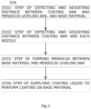
- Fig. 3 is a flowchart illustrating the coating method (S30) according to the second embodiment.
- the coating method for forming and applying a meniscus of a coating liquid includes: a step (S31) of detecting and adjusting a distance between a coating bar and a meniscus leveling bar, and a base material; a step (S32) of detecting and adjusting a distance between the coating bar and each nozzle; a step (S33) of forming a meniscus between the base material and the leveling bar; and a step (S34) of supplying the coating liquid to perform coating on the base material.
- a meniscus M22 is stably formed in a coating process by performing the step of S33 before the step of S34. It is preferable to arrange an additional nozzle that supplies the coating liquid to the leveling bar in order to form a meniscus between the base material and the leveling bar before the start of coating as described above.
- each nozzle can be installed on one cantilever fixing plate capable of rotation, horizontal movement, or vertical movement. With such an arrangement, it is possible to simultaneously adjust positions of all the nozzles.
- a solar cell can be formed by coating with the coating device 100.
- the number of pumps is four.
- a pipe connected to one pump is connected to four nozzles.
- the total number of nozzles is 16.
- the nozzle is installed on one cantilever bar.
- An actuator for movement and a wiring for measuring the electric resistance are installed in each nozzle.
- the wiring is connected to the electric resistance measuring instrument.
- the nozzle position detection member such as a camera for observing a positional relationship between the nozzle and the coating bar is installed.
- the base material 107 is a roll-shaped PET film.
- a width of the PET film is, for example, 330 mm.
- a light-transmissive electrode having a width of 300 mm is formed on the PET film by a roll-to-roll sputtering device.
- a sheet resistance of the electrode is, for example, 10 ⁇ / ⁇ .
- the electrode has, for example, a laminated structure of ITO film/Ag alloy/ITO film.
- a plurality of electrodes are provided. A length of one of the plurality of electrodes is, for example, about 10 mm. An interval between the plurality of electrodes is, for example, 50 ⁇ m.
- Cross sections of the coating bar 101 and the leveling bar 105 are circular.
- a radius of the circle is 10 mm.
- a length of the coating bar 101 and the leveling bar 105 is 300 mm.
- the coating bar 101 and the leveling bar 105 contain, for example, stainless steel (for example, SUS303).
- the nozzle includes a stainless steel locking base.
- the length of the nozzle is 50 mm.
- a pipe for the coating liquid is a polytetrafluoroethylene tube.
- the nozzle and the pipe are connected by a detachable joint.
- the pipe is connected to the pump.
- a hole transport layer is formed by the coating liquid 103.
- the coating liquid 103 is an aqueous solution containing PEDOT and PSS.
- the gap ring or the actuator controls a relative positional relationship between the coating bar 101 and the leveling bar 105, and the base material 107.
- the nozzle is brought into a horizontal state. In such a state, the coating liquid 103 is supplied, and air in the nozzle is discharged.
- the tip of the needle nozzle is lowered and inclined by 20° from the horizontal state.
- the cantilever is brought close to the coating bar.
- each nozzle is brought close to and into contact with the coating bar one by one such that the electric resistance becomes 10 to 50 ⁇ .
- the coating liquid is supplied to the leveling bar 105 with a syringe to form the meniscus 103Mb between the leveling bar 105 and the base material 107.
- the coating liquid 103 is continuously supplied by the pump while the base material 107 is conveyed.
- a movement speed of the base material 107 is, for example, 5 m/min.
- the drying member 109 blows heated dry air to the applied coating liquid 103.
- a solidified coating film is obtained from the coating liquid 103.
- another coating liquid may be further applied after the above coating.
- the another coating liquid contains, for example, a semiconductor material.
- the another coating liquid contains, for example, PTB7 ([poly ⁇ 4,8-bis[(2-ethylhexyl)oxy]benzo[1,2-b:4,5-b']dithiophene-2,6-diyl-1t-alt-3-fluoro-2-[(2-ethylhexyl)carbonyl]thieno[3,4-b]thiophene-4,6-diyl ⁇ ]) and PC70BM ([6,6]-phenyl-C71-butyric acid methylester).
- PTB7 is, for example, a p-type semiconductor.
- PC70BM is, for example, an n-type semiconductor.
- the another coating liquid further contains, for example, monochlorobenzene.
- An amount of PTB7 is 8 mg for 1 mL of monochlorobenzene.
- An amount of PC70BM is 12 mg for 1 mL of monochlorobenzene.
- the another coating liquid is a dispersion liquid containing an organic semiconductor.
- the another coating liquid is, for example, a semiconductor film of a solar cell.
- a minimum distance between the coating bar 101 and the base material 107 is 300 ⁇ m.
- the movement speed of the base material 107 is, for example, 5 m/min. After the coating, drying is performed by the drying member 109.
- an organic thin-film solar cell using an organic semiconductor and an organic/inorganic hybrid solar cell By preparing such solar cells by the coating method, a high-performance solar cell can be prepared.
- the coating liquid 103 may be applied to the base material 107 at a position where the base material 107 is conveyed in a vertical direction.
- an effect of gravity is applied to the meniscus, and a uniform film is easily obtained even at high speed.
- the coating device and the coating method capable of forming a uniform coating film are provided.
Landscapes
- Engineering & Computer Science (AREA)
- Manufacturing & Machinery (AREA)
- Physics & Mathematics (AREA)
- Electromagnetism (AREA)
- Coating Apparatus (AREA)
Abstract
Description
- Embodiments of the present invention relate to a coating device and a coating method that can be used for device formation.
- Organic thin-film solar cells using an organic semiconductor and organic/inorganic hybrid solar cells are expected as low-cost solar cells because an inexpensive coating method can be applied to form an active layer. In order to implement the organic thin-film solar cell and the organic/inorganic hybrid solar cell at low cost, it is required to uniformly apply a coating material for forming an organic active layer and other layers. The thickness of each layer is about several nm to several 100 nm, and it is required to form such a very thin layer with a large area and high uniformity. For example, a meniscus coating method or a slit coating method is known as a roll-to-roll (R2R) coating method capable of forming an extremely thin layer over a large area at low cost. However, it may be difficult to obtain a uniform thickness only by adopting these known methods according to related arts as they are, and a coating device capable of forming a uniform coating film by applying a liquid using a uniform coating bar is desired.
- Patent Literature 1:
JP 2003-251256 A - Embodiments of the present invention provide a coating device and a coating method capable of forming a uniform coating film.
- Embodiments provided by the present invention are as follows:
- [1] A coating device including: a coating bar; a base material conveyance member that conveys a base material; and a coating liquid supply member that supplies a coating liquid to said coating bar, in which said coating device further includes a leveling bar provided at a position downstream of said coating bar in a coating direction, and said leveling bar is arranged at a position where said coating liquid forms a meniscus between said leveling bar and said base material.
- [2] The coating device according to [1], further including a leveling bar position adjustment member that controls an interval between said leveling bar and said base material.
- [3] The coating device according to [1] or [2], in which said leveling bar is arranged so as not to rotate.
- [4] The coating device according to any one of [1] to [3], further including a coating bar position adjustment member that controls a position of said coating bar.
- [5] The coating device according to any one of [1] to [4], in which said coating liquid is supplied from a plurality of nozzles.
- [6] The coating device according to [5], in which opening surfaces of the plurality of nozzles have a needle shape cut to an angle of 75 degrees or more and 105 degrees or less.
- [7] The coating device according to [5] or [6], in which said nozzle is detachable.
- [8] The coating device according to any one of [5] to [7], further including a nozzle that supplies said coating liquid to said leveling bar.
- [9] The coating device according to any one of [1] to [4], in which said coating liquid is supplied from a slit die head.
- [10] The coating device according to any one of [1] to [9], in which said leveling bar is curved.
- [11] A coating method for preparing a coating film by applying a coating liquid to a surface of a base material using a coating bar, said coating method including: arranging a leveling bar at a position downstream of said coating bar in a coating direction; and forming a meniscus between said base material and said leveling bar by said coating liquid supplied from a primary coating film formed by said coating bar to form a secondary coating film.
- [12] The coating method according to [11], in which said coating liquid is supplied from a plurality of nozzles to a surface of said coating bar, and said coating liquid is supplied from said surface to between said coating bar and said base material to form the primary coating film.
- [13] The coating method according to [12], in which said coating liquid is supplied after adjusting positions of the plurality of nozzles and detecting a distance between said coating bar and the plurality of nozzles.
- [14] The coating method according to [13], in which said distance is detected by measuring an electric resistance between said nozzle and said coating bar.
- [15] The coating method according to any one of [12] to [14], in which the plurality of nozzles are installed on one cantilever fixing plate capable of rotation, horizontal movement, or vertical movement.
-
- [
Fig. 1] Fig. 1 is a schematic side view illustrating a coating device according to a first embodiment. - [
Fig. 2] Fig. 2 is a schematic top view illustrating the coating device according to the first embodiment. - [
Fig. 3] Fig. 3 is a flowchart illustrating a coating method according to a second embodiment. - Hereinafter, embodiments of the present invention will be described in detail with reference to the drawings.
- Note that the drawings are schematic or conceptual, and a relationship between a thickness and a width of each portion, a ratio between sizes of portions, and the like are not necessarily the same as actual ones. In addition, even in a case of representing the same portion, dimensions and ratios may be illustrated differently from each other depending on the drawings.
- Note that, in the present specification and the respective drawings, elements similar to those described above in the previously described drawings are denoted by the same reference numerals, and the detailed description thereof is appropriately omitted.
-
Fig. 1 is a schematic side view illustrating a coating device according to a first embodiment.Fig. 2 is a schematic top view illustrating the coating device according to the first embodiment. - As illustrated in
Fig. 1 , acoating device 100 according to the embodiment includes acoating bar 101, a basematerial conveyance member 102 that conveys a base material, a coatingliquid supply member 104 that supplies acoating liquid 103 stored in aliquid reservoir 112 to the coating bar, and aleveling bar 105. Theleveling bar 105 is arranged at a position where the coating liquid forms a meniscus between the leveling bar and the base material. Then, in this example, a primary coating film is formed by a so-called meniscus method using the coating bar. Each member is arranged such that thecoating liquid 103 is supplied from anozzle 106 to a surface of thecoating bar 101, the coating liquid flows from the surface of the coating bar to between thecoating bar 101 and abase material 107 to form a meniscus 103Ma, and the base material is conveyed in an arrow direction to form aprimary coating film 108a. - In the embodiment, a cross-sectional shape of the
coating bar 101 is arbitrary. The cross-sectional shape is, for example, a circular shape, a flat circular shape, or a polygonal shape. A portion of the cross-sectional shape that corresponds to a meniscus forming portion may be curved, and the other portion may be linear. For example, a cross-sectional shape of a surface of thecoating bar 101 that faces thebase material 107 may be curved. - The coating bar can be arranged so as not to rotate. As the coating bar does not rotate like a roller, stability of the meniscus is improved.
- The
coating bar 101 contains, for example, at least one selected from the group consisting of stainless steel, aluminum, titanium, and glass. Therefore, processing is facilitated when preparing thecoating bar 101. In one example, the surface of thecoating bar 101 is a mirror surface. In another example, the surface of thecoating bar 101 may have an uneven structure. - Then, as illustrated in
Figs. 1 and 2 , theleveling bar 105 is installed at a position downstream of thecoating bar 101 in a coating direction. - The
coating bar 101 applies thecoating liquid 103 to almost the entire surface of thebase material 107 to form thecoating film 108a, but uniformity of thecoating film 108a may be insufficient. Thecoating film 108a formed in the present embodiment comes into contact with theleveling bar 105 arranged at a position downstream of the coating bar as the base material is conveyed. As illustrated inFig. 1 , the meniscus 103Mb of thecoating liquid 103 can be formed between thebase material 107 and theleveling bar 105. As thecoating liquid 103 spreads in a lateral direction of a gap between theleveling bar 105 and thebase material 107, the uniform meniscus 103Mb is formed by a surface tension of the coating liquid. When the meniscus 103Mb comes into contact with thebase material 107, asecondary coating film 108b having high uniformity and formed by thecoating 103 is formed on thebase material 107. An intended film (solid film) is obtained by solidifying thecoating film 108b by, for example, drying. For example, adrying member 109 can be arranged at a position downstream of the leveling bar. - As described above, the
coating film 108b having a large area can be formed on thebase material 107, for example, by moving thebase material 107 in a movement direction (an arrow direction in the drawing). - The coating device illustrated in
Figs. 1 and 2 forms the primary coating film by the meniscus method, and the coating device may further include a nozzleposition adjustment member 110 that adjusts a position of thenozzle 106, a nozzleposition detection member 111 that detects a distance between thecoating bar 101 and thenozzle 106, and the like in order to improve the uniformity of the primary coating film. - In a case where the nozzle is used to form the primary coating film, a plurality of
nozzles 106 or a plurality ofpumps 104 can be used as illustrated inFig. 2 . The plurality ofnozzles 106 can face thecoating bar 101. As illustrated inFig. 2 , the plurality ofnozzles 106 can supply thecoating liquid 103 toward thecoating bar 101. Note that an additional nozzle for supplying the coating liquid to the levelingbar 105 may be further provided. It is possible to form a meniscus between the base material and the leveling bar before forming the primary coating film before the coating is started by arranging such an additional nozzle. - As illustrated in
Fig. 2 , the plurality ofnozzles 106 are arranged in a first direction. The first direction is, for example, a Y-axis direction. One direction perpendicular to the Y-axis direction is defined as an X-axis direction. The movement direction of the base material can coincide with an X axis. A direction perpendicular to the Y-axis direction and the X-axis direction is defined as a Z-axis direction. Thecoating bar 101 extends, for example, in the Y-axis direction. - In the embodiment, the number of plurality of
nozzles 106 may be three or more. As a result, theprimary coating film 108a having a large area can be stably formed. In the example ofFig. 2 , the number of plurality ofnozzles 106 is four. In the embodiment, the number may be an arbitrary integer of 3 or more. - In the embodiment, the nozzle can be a slot die or can have a needle shape. For example, a discharge amount of the
coating liquid 103 can be controlled with high accuracy by using the plurality of needle-shapednozzles 106. When the nozzle has the needle shape, for example, tips of the plurality of nozzles are easily brought into contact with thecoating bar 101. The needle-shaped nozzle has high flexibility. Due to the high flexibility, for example, damage to the nozzle due to vibration of thecoating bar 101 or the like can be suppressed. In the needle-shaped nozzle, a length of the nozzle is, for example, 10 mm or more and 100 mm or less, and an inner diameter of the nozzle is, for example, 0.5 mm or more and 2 mm or less. An angle between an end surface of the tip of the nozzle and an extending direction of the nozzle is, for example, about 90 degrees (for example, 75 degrees or more and 105 degrees or less). With such a shape, for example, occurrence of scratches on thecoating bar 101 can be suppressed. - However, in a case where there are a plurality of nozzles, a distance between the
coating bar 101 and the tip of each nozzle tends to vary. When there is variation, the meniscus 103Ma formed from each nozzle is likely to be disturbed, and as a result, thecoating film 108a is likely to be non-uniform. - If the nozzle
position adjustment member 110 that adjusts the position of each nozzle and the nozzleposition detection member 111 that detects a distance between thecoating bar 101 and eachnozzle 106 are provided as illustrated inFigs. 1 and 2 , it is possible to reduce variation in the position and the distance between the tip of each nozzle and the coating bar, and to achieve uniform coating. - In the embodiment, a member that detects contact between the coating bar and each nozzle can be further provided. The contact is easily detected by, for example, a method of measuring an electric resistance between the nozzle and the coating bar, and thus, the variation can be reduced by adjusting a coating condition based on the contact. When the nozzle is in contact with the coating bar, the coating liquid can be directly applied to the coating bar, and repelling of the coating liquid hardly occurs.
- In the embodiment, a member that measures the electric resistance between each nozzle and the coating bar can be provided as the member that detects the contact between the coating bar and each nozzle. If each nozzle and the coating bar are made of conductive stainless steel or the like, and the nozzles are insulated from each other, when the electric resistance between the coating bar and each nozzle is measured, the electric resistance is drastically reduced at a moment of contact. In addition, since the electric resistance changes as a contact state changes, the contact state can be monitored. For example, in a state in which the nozzle is pressed against the coating bar so strongly as to be greatly curved, the coating bar comes into contact with not only the tip of the nozzle but also a side surface of the nozzle, and the electric resistance becomes very low. In this case, the coating liquid is easily ejected from the tip of the nozzle to a portion other than the coating bar, and uneven coating is likely to occur. Since an optimum electric resistance varies depending on a shape and material of the nozzle and the coating bar, it is desirable to measure the optimum electric resistance in advance.
- It is desirable to install a wiring connected to an electric resistance measuring instrument between the nozzles and the coating bar in advance. A switching portion is provided in the wiring, and each nozzle can be moved to confirm the contact with the coating bar before coating. If the electric resistance is also measured during the coating, it is possible to detect a case where there is an abnormality in the contact between the nozzle and the coating bar. The electric resistance measuring instrument can also be an external device separate from the coating device.
- Note that, in the coating device according to the embodiment, the nozzle is preferably detachable. The nozzle is likely to be clogged due to a small opening. In the coating device according to the embodiment, when such clogging occurs, an ejection amount from each nozzle can be adjusted by the coating liquid supply member and a coating liquid supply amount adjustment member, but when clogging becomes severe or the ejection becomes completely impossible, it is necessary to perform cleaning or replacement. In such a case, it is preferable that the nozzle is detachable to facilitate maintenance.
- In the above description, a case where the
primary coating film 108a is formed by the meniscus method by supplying the coating liquid from the plurality of nozzles illustrated inFigs. 1 and 2 has been described, but the primary coating film may be formed by another method. For example, a slit die head that uses the coating bar for slit coating, includes a manifold therein, and supplies the coating liquid from the manifold to the surface of the base material via a slit can be used instead of the plurality of nozzles. Further, the coating liquid can be supplied to the coating bar by using the slit die head instead of the nozzle inFigs. 1 and 2 . - The
coating device 100 may further include the dryingmember 109. The dryingmember 109 can dry thecoating film 108b applied to thebase material 107. The dryingmember 109 may include, for example, an air nozzle or a far-infrared lamp. - A distance between the
coating bar 101 and the levelingbar 105 can be freely changed. - In addition, it is preferable to provide a member that controls an interval between the leveling
bar 105 and thebase material 107. For this purpose, a gap ring, a micrometer, or the like can be used. - The leveling bar may be linear or curved. When the leveling bar is linear, uniformity of a thickness of the coating film is easily achieved. When the leveling bar is curved, for example, the thickness is easily changed such that the center is thicker, but the uniformity in the coating direction is easily achieved.
- In the embodiment, a cross-sectional shape of the leveling
bar 105 is arbitrary. The cross-sectional shape is, for example, a circular shape, a flat circular shape, or a polygonal shape. A portion of the cross-sectional shape may be curved, and the other portion may be linear. For example, a cross-sectional shape of a surface of the levelingbar 105 that faces thebase material 107 may be curved. - The leveling bar can be arranged so as not to rotate. As the leveling bar does not rotate like a roller, stability of the meniscus is improved.
- The leveling
bar 105 contains, for example, at least one selected from the group consisting of stainless steel, aluminum, titanium, and glass. Therefore, processing is facilitated when preparing the levelingbar 105. In one example, the surface of the levelingbar 105 is a mirror surface. In another example, the surface of the leveling bar 26 may have an uneven structure. - A second embodiment relates to a coating method. In the coating method according to the embodiment, for example, coating is performed using the coating device 10 (and a modification thereof) described in the first embodiment.
-
Fig. 3 is a flowchart illustrating the coating method (S30) according to the second embodiment. The coating method for forming and applying a meniscus of a coating liquid includes: a step (S31) of detecting and adjusting a distance between a coating bar and a meniscus leveling bar, and a base material; a step (S32) of detecting and adjusting a distance between the coating bar and each nozzle; a step (S33) of forming a meniscus between the base material and the leveling bar; and a step (S34) of supplying the coating liquid to perform coating on the base material. Here, a meniscus M22 is stably formed in a coating process by performing the step of S33 before the step of S34. It is preferable to arrange an additional nozzle that supplies the coating liquid to the leveling bar in order to form a meniscus between the base material and the leveling bar before the start of coating as described above. - In the embodiment, the distance between the coating bar and each nozzle can be detected by measuring an electric resistance between the coating bar and the nozzle. In addition, each nozzle can be installed on one cantilever fixing plate capable of rotation, horizontal movement, or vertical movement. With such an arrangement, it is possible to simultaneously adjust positions of all the nozzles.
- Hereinafter, specific examples of the coating device and the coating method according to the embodiment will be described.
- For example, a solar cell can be formed by coating with the
coating device 100. In one example, the number of pumps is four. A pipe connected to one pump is connected to four nozzles. The total number of nozzles is 16. The nozzle is installed on one cantilever bar. An actuator for movement and a wiring for measuring the electric resistance are installed in each nozzle. The wiring is connected to the electric resistance measuring instrument. The nozzle position detection member such as a camera for observing a positional relationship between the nozzle and the coating bar is installed. - For example, the
base material 107 is a roll-shaped PET film. A width of the PET film is, for example, 330 mm. A light-transmissive electrode having a width of 300 mm is formed on the PET film by a roll-to-roll sputtering device. A sheet resistance of the electrode is, for example, 10 Ω/□. The electrode has, for example, a laminated structure of ITO film/Ag alloy/ITO film. For example, a plurality of electrodes are provided. A length of one of the plurality of electrodes is, for example, about 10 mm. An interval between the plurality of electrodes is, for example, 50 µm. - Cross sections of the
coating bar 101 and the levelingbar 105 are circular. A radius of the circle is 10 mm. A length of thecoating bar 101 and the levelingbar 105 is 300 mm. Thecoating bar 101 and the levelingbar 105 contain, for example, stainless steel (for example, SUS303). - The nozzle includes a stainless steel locking base. The length of the nozzle is 50 mm. A pipe for the coating liquid is a polytetrafluoroethylene tube. The nozzle and the pipe are connected by a detachable joint. The pipe is connected to the pump.
- In one example, a hole transport layer is formed by the
coating liquid 103. In this case, thecoating liquid 103 is an aqueous solution containing PEDOT and PSS. - For example, the gap ring or the actuator controls a relative positional relationship between the
coating bar 101 and the levelingbar 105, and thebase material 107. - For example, the nozzle is brought into a horizontal state. In such a state, the
coating liquid 103 is supplied, and air in the nozzle is discharged. - Thereafter, the tip of the needle nozzle is lowered and inclined by 20° from the horizontal state. The cantilever is brought close to the coating bar. Next, each nozzle is brought close to and into contact with the coating bar one by one such that the electric resistance becomes 10 to 50 Ω.
- The coating liquid is supplied to the leveling
bar 105 with a syringe to form the meniscus 103Mb between the levelingbar 105 and thebase material 107. - The
coating liquid 103 is continuously supplied by the pump while thebase material 107 is conveyed. A movement speed of thebase material 107 is, for example, 5 m/min. The dryingmember 109 blows heated dry air to the appliedcoating liquid 103. A solidified coating film is obtained from thecoating liquid 103. - In the embodiment, another coating liquid may be further applied after the above coating. The another coating liquid contains, for example, a semiconductor material. The another coating liquid contains, for example, PTB7 ([poly{4,8-bis[(2-ethylhexyl)oxy]benzo[1,2-b:4,5-b']dithiophene-2,6-diyl-1t-alt-3-fluoro-2-[(2-ethylhexyl)carbonyl]thieno[3,4-b]thiophene-4,6-diyl}]) and PC70BM ([6,6]-phenyl-C71-butyric acid methylester). PTB7 is, for example, a p-type semiconductor. PC70BM is, for example, an n-type semiconductor. The another coating liquid further contains, for example, monochlorobenzene. An amount of PTB7 is 8 mg for 1 mL of monochlorobenzene. An amount of PC70BM is 12 mg for 1 mL of monochlorobenzene. The another coating liquid is a dispersion liquid containing an organic semiconductor.
- The another coating liquid is, for example, a semiconductor film of a solar cell. When applying the another coating liquid, a minimum distance between the
coating bar 101 and thebase material 107 is 300 µm. The movement speed of thebase material 107 is, for example, 5 m/min. After the coating, drying is performed by the dryingmember 109. - For example, there are an organic thin-film solar cell using an organic semiconductor and an organic/inorganic hybrid solar cell. By preparing such solar cells by the coating method, a high-performance solar cell can be prepared.
- In the embodiment, the
coating liquid 103 may be applied to thebase material 107 at a position where thebase material 107 is conveyed in a vertical direction. As a result, for example, an effect of gravity is applied to the meniscus, and a uniform film is easily obtained even at high speed. - According to the embodiments, the coating device and the coating method capable of forming a uniform coating film are provided.
- The embodiments of the present invention have been described above with reference to specific examples. However, the present invention is not limited to the specific examples. For example, a specific configuration of each element such as the pipe, the pump, the nozzle, and a holding unit included in the coating device is included in the scope of the present invention as long as those skilled in the art can similarly carry out the present invention and obtain the same effect by appropriately selecting the configuration from known ranges.
- In addition, a combination of any two or more elements of the respective specific examples within a technically possible range is also included in the scope of the present invention as long as the combination includes the gist of the present invention.
- In addition, all the coating devices and coating methods that can be implemented by those skilled in the art by appropriately changing the design based on a coating head, the coating device, and the coating method described above as the embodiments of the present invention are also within the scope of the present invention as long as the coating devices and coating methods include the gist of the present invention.
- In addition, those skilled in the art can conceive various changes and modifications within the scope of the idea of the present invention, and it is understood that the changes and modifications also fall within the scope of the present invention.
- Although some embodiments of the present invention have been described, the embodiments have been presented as examples and are not intended to limit the scope of the invention. These novel embodiments can be implemented in various other forms, and various omissions, substitutions, and changes can be made without departing from the gist of the invention. The embodiments and modifications thereof are included in the scope and gist of the invention, and are included in the invention described in the claims and the equivalent scope thereof.
-
- 100
- COATING DEVICE
- 101
- COATING BAR
- 102
- BASE MATERIAL CONVEYANCE MEMBER
- 103
- COATING LIQUID
- 104
- COATING LIQUID SUPPLY MEMBER
- 105
- LEVELING BAR
- 106
- NOZZLE
- 107
- BASE MATERIAL
- 108a
- PRIMARY COATING FILM
- 108b
- SECONDARY COATING FILM
- 109
- DRYING MEMBER
- 110
- NOZZLE POSITION ADJUSTMENT MEMBER
- 111
- NOZZLE POSITION DETECTION MEMBER
- 112
- LIQUID RESERVOIR
Claims (15)
- A coating device comprising: a coating bar; a base material conveyance member that conveys a base material; and a coating liquid supply member that supplies a coating liquid to said coating bar, wherein said coating device further comprises a leveling bar provided at a position downstream of said coating bar in a coating direction, and said leveling bar is arranged at a position where said coating liquid forms a meniscus between said leveling bar and said base material.
- The coating device according to claim 1, further comprising a leveling bar position adjustment member that controls an interval between said leveling bar and said base material.
- The coating device according to claim 1 or 2, wherein said leveling bar is arranged so as not to rotate.
- The coating device according to claim 1 or 2, further comprising a coating bar position adjustment member that controls a position of said coating bar.
- The coating device according to claim 1 or 2, wherein said coating liquid is supplied from a plurality of nozzles.
- The coating device according to claim 5, wherein opening surfaces of the plurality of nozzles have a needle shape cut to an angle of 75 degrees or more and 105 degrees or less.
- The coating device according to claim 5, wherein said nozzle is detachable.
- The coating device according to claim 5, further comprising a nozzle that supplies said coating liquid to said leveling bar.
- The coating device according to claim 1 or 2, wherein said coating liquid is supplied from a slit die head.
- The coating device according to claim 1 or 2, wherein said leveling bar is curved.
- A coating method for preparing a coating film by applying a coating liquid to a surface of a base material using a coating bar, said coating method comprising: arranging a leveling bar at a position downstream of said coating bar in a coating direction; and forming a meniscus between said base material and said leveling bar by said coating liquid supplied from a primary coating film formed by said coating bar to form a secondary coating film.
- The coating method according to claim 11, wherein said coating liquid is supplied from a plurality of nozzles to a surface of said coating bar, and said coating liquid is supplied from said surface to between said coating bar and said base material to form said primary coating film.
- The coating method according to claim 12, wherein said coating liquid is supplied after adjusting positions of the plurality of nozzles and detecting a distance between said coating bar and said plurality of nozzles.
- The coating method according to claim 13, wherein said distance is detected by measuring an electric resistance between said nozzle and said coating bar.
- The coating method according to claim 12, wherein the plurality of nozzles are installed on one cantilever fixing plate capable of rotation, horizontal movement, or vertical movement.
Applications Claiming Priority (1)
| Application Number | Priority Date | Filing Date | Title |
|---|---|---|---|
| PCT/JP2023/008884 WO2024185092A1 (en) | 2023-03-08 | 2023-03-08 | Coating apparatus and coating method |
Publications (2)
| Publication Number | Publication Date |
|---|---|
| EP4557352A1 true EP4557352A1 (en) | 2025-05-21 |
| EP4557352A4 EP4557352A4 (en) | 2026-05-06 |
Family
ID=92674515
Family Applications (1)
| Application Number | Title | Priority Date | Filing Date |
|---|---|---|---|
| EP23926302.3A Pending EP4557352A4 (en) | 2023-03-08 | 2023-03-08 | COATING DEVICE AND COATING PROCESS |
Country Status (5)
| Country | Link |
|---|---|
| US (1) | US20250178021A1 (en) |
| EP (1) | EP4557352A4 (en) |
| JP (1) | JP7714830B2 (en) |
| CN (1) | CN119731773A (en) |
| WO (1) | WO2024185092A1 (en) |
Family Cites Families (14)
| Publication number | Priority date | Publication date | Assignee | Title |
|---|---|---|---|---|
| JPS58202077A (en) * | 1982-05-19 | 1983-11-25 | Fuji Photo Film Co Ltd | Method and apparatus for metering coating liquid |
| US4887547A (en) * | 1985-07-31 | 1989-12-19 | Jagenberg Aktiengesellschaft | Apparatus for continuously applying a uniform coating to a material web |
| DE19946325A1 (en) * | 1999-09-28 | 2001-04-05 | Vits Maschinenbau Gmbh | Device for applying an abrasive coating compound to a continuous paper web |
| US7048969B2 (en) * | 2001-09-28 | 2006-05-23 | Fuji Photo Film Co., Ltd. | Coating device and coating method |
| JP2003251256A (en) | 2002-03-06 | 2003-09-09 | Fuji Photo Film Co Ltd | Coating apparatus and coating method |
| JP4696814B2 (en) * | 2005-09-26 | 2011-06-08 | 東レ株式会社 | Coating rod, coating apparatus and method using the same, and film manufacturing apparatus and method |
| JP6256265B2 (en) * | 2014-09-05 | 2018-01-10 | Jfeスチール株式会社 | Slurry coating apparatus and slurry coating method |
| JP6647169B2 (en) * | 2016-07-27 | 2020-02-14 | 富士フイルム株式会社 | Method for producing transdermal absorption sheet |
| EP4029614A4 (en) * | 2019-09-10 | 2023-06-14 | Kabushiki Kaisha Toshiba | COATING PROCESS, COATING ROD HEAD AND COATING DEVICE |
| JP7204890B2 (en) * | 2019-09-10 | 2023-01-16 | 株式会社東芝 | Electrode manufacturing method and photoelectric conversion element manufacturing method |
| CN113613798A (en) * | 2020-03-04 | 2021-11-05 | 株式会社东芝 | Coating method and coating apparatus usable for forming device |
| EP4119237B1 (en) * | 2020-03-09 | 2025-12-24 | Kabushiki Kaisha Toshiba | Coating head, coating device, and coating method |
| EP4194104A4 (en) * | 2020-08-04 | 2024-05-29 | Kabushiki Kaisha Toshiba | APPLICATION DEVICE AND APPLICATION METHOD |
| EP4302882A4 (en) * | 2021-03-04 | 2025-01-29 | Kabushiki Kaisha Toshiba | Coating apparatus and coating method |
-
2023
- 2023-03-08 JP JP2025505004A patent/JP7714830B2/en active Active
- 2023-03-08 CN CN202380059793.1A patent/CN119731773A/en active Pending
- 2023-03-08 WO PCT/JP2023/008884 patent/WO2024185092A1/en not_active Ceased
- 2023-03-08 EP EP23926302.3A patent/EP4557352A4/en active Pending
-
2025
- 2025-02-12 US US19/051,515 patent/US20250178021A1/en active Pending
Also Published As
| Publication number | Publication date |
|---|---|
| EP4557352A4 (en) | 2026-05-06 |
| WO2024185092A1 (en) | 2024-09-12 |
| US20250178021A1 (en) | 2025-06-05 |
| CN119731773A (en) | 2025-03-28 |
| JP7714830B2 (en) | 2025-07-29 |
| JPWO2024185092A1 (en) | 2024-09-12 |
Similar Documents
| Publication | Publication Date | Title |
|---|---|---|
| US20240399406A1 (en) | Coating device, meniscus head, and coating method | |
| US20250178015A1 (en) | Coating device and coating method | |
| US20220161292A1 (en) | Coating apparatus and coating method | |
| US20210408378A1 (en) | Coating process and coating apparatus usable for device formation | |
| CN113631277B (en) | Coating head, coating device and coating method | |
| US11623238B2 (en) | Coating method, coating bar head and coating apparatus | |
| WO2018072545A1 (en) | Coating method, coating apparatus and light-emitting device | |
| US20250178021A1 (en) | Coating device and coating method | |
| US20250187034A1 (en) | Coating head, coating device, and coating method | |
| JPWO2018061691A1 (en) | Method of producing membrane | |
| KR20180019346A (en) | Composition for electrohydrodynamic printing | |
| US8733271B2 (en) | Method and apparatus for continuous coating | |
| JP7560681B2 (en) | Coating device and coating method | |
| JPWO2012002423A1 (en) | Method for forming organic thin film layer, method for producing organic electroluminescence element | |
| JP2004141698A (en) | Method of forming resist pattern, method of manufacturing solar cell using the same, and resist pattern forming apparatus | |
| KR20160069799A (en) | Manufacturing Method and Apparatus for Lagre-Area Thin Film |
Legal Events
| Date | Code | Title | Description |
|---|---|---|---|
| STAA | Information on the status of an ep patent application or granted ep patent |
Free format text: STATUS: THE INTERNATIONAL PUBLICATION HAS BEEN MADE |
|
| PUAI | Public reference made under article 153(3) epc to a published international application that has entered the european phase |
Free format text: ORIGINAL CODE: 0009012 |
|
| STAA | Information on the status of an ep patent application or granted ep patent |
Free format text: STATUS: REQUEST FOR EXAMINATION WAS MADE |
|
| 17P | Request for examination filed |
Effective date: 20250214 |
|
| AK | Designated contracting states |
Kind code of ref document: A1 Designated state(s): AL AT BE BG CH CY CZ DE DK EE ES FI FR GB GR HR HU IE IS IT LI LT LU LV MC ME MK MT NL NO PL PT RO RS SE SI SK SM TR |
|
| REG | Reference to a national code |
Ref country code: DE Ref legal event code: R079 Free format text: PREVIOUS MAIN CLASS: H01L0021368000 Ipc: B05C0001080000 |
|
| A4 | Supplementary search report drawn up and despatched |
Effective date: 20260410 |
|
| RIC1 | Information provided on ipc code assigned before grant |
Ipc: B05C 1/08 20060101AFI20260402BHEP Ipc: B05C 11/02 20060101ALI20260402BHEP Ipc: B05D 1/42 20060101ALI20260402BHEP |