EP4556897A1 - Photography jig and information processing device - Google Patents
Photography jig and information processing device Download PDFInfo
- Publication number
- EP4556897A1 EP4556897A1 EP23839354.0A EP23839354A EP4556897A1 EP 4556897 A1 EP4556897 A1 EP 4556897A1 EP 23839354 A EP23839354 A EP 23839354A EP 4556897 A1 EP4556897 A1 EP 4556897A1
- Authority
- EP
- European Patent Office
- Prior art keywords
- movement
- imaging
- information
- mark
- radiographic image
- Prior art date
- Legal status (The legal status is an assumption and is not a legal conclusion. Google has not performed a legal analysis and makes no representation as to the accuracy of the status listed.)
- Pending
Links
Images









Classifications
-
- G—PHYSICS
- G01—MEASURING; TESTING
- G01N—INVESTIGATING OR ANALYSING MATERIALS BY DETERMINING THEIR CHEMICAL OR PHYSICAL PROPERTIES
- G01N23/00—Investigating or analysing materials by the use of wave or particle radiation, e.g. X-rays or neutrons, not covered by groups G01N3/00 – G01N17/00, G01N21/00 or G01N22/00
- G01N23/02—Investigating or analysing materials by the use of wave or particle radiation, e.g. X-rays or neutrons, not covered by groups G01N3/00 – G01N17/00, G01N21/00 or G01N22/00 by transmitting the radiation through the material
- G01N23/04—Investigating or analysing materials by the use of wave or particle radiation, e.g. X-rays or neutrons, not covered by groups G01N3/00 – G01N17/00, G01N21/00 or G01N22/00 by transmitting the radiation through the material and forming images of the material
- G01N23/046—Investigating or analysing materials by the use of wave or particle radiation, e.g. X-rays or neutrons, not covered by groups G01N3/00 – G01N17/00, G01N21/00 or G01N22/00 by transmitting the radiation through the material and forming images of the material using tomography, e.g. computed tomography [CT]
-
- G—PHYSICS
- G01—MEASURING; TESTING
- G01N—INVESTIGATING OR ANALYSING MATERIALS BY DETERMINING THEIR CHEMICAL OR PHYSICAL PROPERTIES
- G01N23/00—Investigating or analysing materials by the use of wave or particle radiation, e.g. X-rays or neutrons, not covered by groups G01N3/00 – G01N17/00, G01N21/00 or G01N22/00
- G01N23/02—Investigating or analysing materials by the use of wave or particle radiation, e.g. X-rays or neutrons, not covered by groups G01N3/00 – G01N17/00, G01N21/00 or G01N22/00 by transmitting the radiation through the material
- G01N23/04—Investigating or analysing materials by the use of wave or particle radiation, e.g. X-rays or neutrons, not covered by groups G01N3/00 – G01N17/00, G01N21/00 or G01N22/00 by transmitting the radiation through the material and forming images of the material
-
- G—PHYSICS
- G01—MEASURING; TESTING
- G01N—INVESTIGATING OR ANALYSING MATERIALS BY DETERMINING THEIR CHEMICAL OR PHYSICAL PROPERTIES
- G01N2223/00—Investigating materials by wave or particle radiation
- G01N2223/30—Accessories, mechanical or electrical features
- G01N2223/309—Accessories, mechanical or electrical features support of sample holder
-
- G—PHYSICS
- G01—MEASURING; TESTING
- G01N—INVESTIGATING OR ANALYSING MATERIALS BY DETERMINING THEIR CHEMICAL OR PHYSICAL PROPERTIES
- G01N2223/00—Investigating materials by wave or particle radiation
- G01N2223/30—Accessories, mechanical or electrical features
- G01N2223/321—Accessories, mechanical or electrical features manipulator for positioning a part
-
- G—PHYSICS
- G01—MEASURING; TESTING
- G01N—INVESTIGATING OR ANALYSING MATERIALS BY DETERMINING THEIR CHEMICAL OR PHYSICAL PROPERTIES
- G01N2223/00—Investigating materials by wave or particle radiation
- G01N2223/40—Imaging
- G01N2223/417—Imaging recording with co-ordinate markings
-
- G—PHYSICS
- G01—MEASURING; TESTING
- G01N—INVESTIGATING OR ANALYSING MATERIALS BY DETERMINING THEIR CHEMICAL OR PHYSICAL PROPERTIES
- G01N2223/00—Investigating materials by wave or particle radiation
- G01N2223/40—Imaging
- G01N2223/419—Imaging computed tomograph
Definitions
- the disclosed technology relates to an imaging jig and an information processing apparatus.
- JP2018-179657A describes an X-ray inspection apparatus including an X-ray irradiation source, a table on which an object to be irradiated is to be placed, and an X-ray detector that receives X-rays transmitted through the object to be irradiated and detects a transmission image thereof.
- JP2013-15426A describes a radiation CT apparatus that performs pre-imaging to capture an image of a photographic subject at a placement position on a table, followed by main imaging to capture an image of a sample after moving the table and a radiation detector in the same manner as in the pre-imaging, and then reconstructs a tomographic image.
- Tomosynthesis is known as an imaging technique for reconstructing a cross-sectional plane at a desired depth position in a single tomographic imaging session.
- One generally known reconstruction processing method using tomosynthesis is a method called a shift-and-add method.
- the shift-and-add method is a method that shifts, for a series of radiographic images continuously captured while changing the relative positional relationship between a radiation source and an imaging target, each image by an appropriate amount in a scanning direction and superimposes the results to obtain a tomographic image focused on a specific cross-sectional plane. Adjusting the shift amount for each image makes it possible to obtain a tomographic image of any cross-sectional plane.
- an imaging apparatus including a tomosynthesis function acquires a series of radiographic images by changing an imaging direction by robot control.
- the relative positional relationship of the imaging target depicted in the series of radiographic images can be easily calculated by cooperation with the robot control for the imaging direction.
- the imaging apparatus including the tomosynthesis function can easily obtain a tomographic image, but is expensive and is not easily accessible.
- a method for acquiring a tomographic image using an imaging apparatus that does not include the tomosynthesis function is considered. It is possible to acquire a plurality of radiographic images from different imaging directions by manually moving the position of the imaging target such that the relative positional relationship between the radiation source and the imaging target changes. In this case, however, it is not easy to acquire accurate relative positional information for each of the plurality of radiographic images from different imaging directions. In addition, it is necessary to manually associate the radiographic images with their corresponding relative positional information.
- the disclosed technology has been developed in view of the above points, and an object thereof is to support the acquisition of relative positional information and the association between a radiographic image and the relative positional information.
- An imaging jig is an imaging jig to be used for capturing a radiographic image of an imaging target irradiated with radiation.
- the imaging jig includes a movement mechanism that moves a position of the imaging target such that a relative positional relationship between a radiation source that emits the radiation and the imaging target changes; and a display portion in which movement amount information indicating an amount of movement of the imaging target from an initial position is to be displayed. The movement amount information is distinguishably depicted in the radiographic image.
- the movement mechanism may translationally or rotationally move the imaging target.
- a display of the movement amount information may change in conjunction with an operation of the movement mechanism.
- the movement amount information may be displayed by a mark made of a material having a different transmittance to the radiation from a material of the movement mechanism.
- the movement mechanism may include a fixed unit having a fixed relative positional relationship with the radiation source, and a moving unit provided to be movable with respect to the fixed unit.
- the imaging target may move along with a movement of the moving unit.
- the display portion may include a first mark provided on the fixed unit and a second mark provided on the moving unit. The display portion may display the movement amount information based on a relative positional relationship between the first mark and the second mark.
- An information processing apparatus includes at least one processor and is for processing a radiographic image captured using the above-described imagingjig.
- the at least one processor is configured to acquire the radiographic image and recognize movement amount information depicted in the radiographic image.
- the at least one processor may be configured to recognize the movement amount information included in the radiographic image by matching the movement amount information against a template pattern corresponding to the movement amount information.
- a position detection mark for detecting a display position of the movement amount information may be distinguishably depicted in the radiographic image.
- the at least one processor may be configured to detect a position of the movement amount information included in the radiographic image, based on the position detection mark included in the radiographic image.
- the at least one processor may be configured to record movement-amount-information-associated image data in a recording medium, the movement-amount-information-associated image data being obtained by associating the movement amount information and the radiographic image with each other.
- the at least one processor may be configured to generate a tomographic image of the imaging target using a plurality of pieces of the movement-amount-information-associated data recorded in the recording medium for a plurality of radiographic images with different relative positional relationships between the radiation source and the imaging target.
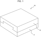
- Fig. 1 is a perspective view of an example of a configuration of an imaging jig 10 according to an embodiment of the disclosed technology.
- the imaging jig 10 is a holding device to be used for capturing a radiographic image of an imaging target irradiated with radiation.
- the imaging jig 10 includes a fixed unit 11 and a moving unit 12.
- the fixed unit 11 has a fixed relative position with respect to a radiation source (not illustrated) that emits radiation.
- the moving unit 12 is provided to be movable with respect to the fixed unit 11.
- the fixed unit 11 and the moving unit 12 are examples of a "movement mechanism" in the disclosed technology.
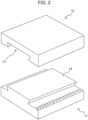
- Fig. 2 is an exploded perspective view of the fixed unit 11 and the moving unit 12.
- the moving unit 12 is provided with, in a contact surface thereof with the fixed unit 11, a guide groove 13 that extends linearly.
- the fixed unit 11 is provided with, on a contact surface thereof with the moving unit 12, a convex guide rail 14 that extends linearly.
- the moving unit 12 can move linearly (translationally move) on the fixed unit 11 along the guide rail 14 with the guide rail 14 fitted in the guide groove 13. That is, the imaging jig 10 functions as a so-called linear motion stage.
- the movement of the moving unit 12 can be performed manually or automatically.
- Fig. 4A is a plan view of the moving unit 12 as viewed from the side of the contact surface with the fixed unit 11.
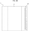
- Fig. 4B is a plan view of the fixed unit 11 as viewed from the side of the contact surface with the moving unit 12.
- the contact surfaces of the fixed unit 11 and the moving unit 12 are provided with marks 20A and 20B, respectively, for displaying movement amount information indicating the amount of movement of the moving unit 12 from an initial position.
- the portions of the imaging jig 10 where the mark 20A and the mark 20B are formed are examples of a "display portion" in the disclosed technology.
- the mark 20A is a linear scale with numerical values assigned to the scale, the scale extending along the extension direction of the guide rail 14, and is drawn on the outside of the guide rail 14.
- the mark 20B is a pointer pointing to a position on the mark 20A (scale), and is drawn on the outside of the guide groove 13.
- the initial position can be determined as desired. For example, as illustrated in Fig. 1 , the initial position may be set as a position where an end surface of the fixed unit 11 and an end surface of the moving unit 12 are aligned with each other in the movement direction of the moving unit 12.
- Figs. 5A and 5B are perspective views of the mark 20A and the mark 20B when the imaging jig 10 is viewed from the upper surface side of the moving unit 12.
- Fig. 5A illustrates a case where the moving unit 12 is positioned at the initial position
- Fig. 5B illustrates a case where the moving unit 12 is positioned at a movement position displaced from the initial position.
- a numerical value N1 indicating a position pointed to by the mark 20B (pointer) on the mark 20A (scale) is typically "0".
- the position pointed to by the mark 20B (pointer) on the mark 20A (scale) changes accordingly.
- a numerical value N2 indicating the position pointed to by the mark 20B (pointer) on the mark 20A (scale) at the movement position indicates the amount of movement of the moving unit 12 from the initial position.
- the display of the movement amount information by the marks 20A and 20B changes in conjunction with the operation of the moving unit 12.
- the numerical value N1 indicating the position pointed to by the mark 20B (pointer) on the mark 20A (scale) when the moving unit 12 is positioned at the initial position need not be "0".
- the difference between the numerical value N2 at the movement position and the numerical value N1 at the initial position (N2 - N1) corresponds to the amount of movement of the moving unit 12.
- the fixed unit 11 and the moving unit 12 are made of a material having a relatively high transmittance to radiation (X-rays).
- Examples of the material of the fixed unit 11 and the moving unit 12 may include plastics such as polyethylene (PE), polypropylene (PP), polyethylene terephthalate (PET), and polystyrene (PS).
- the marks 20A and 20B are drawn on the moving unit 12 and the fixed unit 11, respectively, using a material having a relatively low transmittance to radiation (X-rays).
- Examples of the material of the marks 20A and 20B may include metals such as aluminum, copper, and lead.
- the material of the marks 20A and 20B has a lower transmittance to radiation (X-rays) than the material of the fixed unit 11 and the moving unit 12.
- the movement amount information can be depicted in a radiographic image captured using the imaging jig 10.
- Figs. 6A and 6B are side views illustrating an example of a method of using the imaging jig 10.
- Fig. 6A illustrates a case where the moving unit 12 is positioned at the initial position
- Fig. 6B illustrates a case where the moving unit 12 is positioned at a movement position displaced from the initial position.
- an imaging target 50 for a radiographic image is placed on top of the moving unit 12, and a radiation detector 30 is disposed under the fixed unit 11.
- a radiation source 40 that emits radiation is disposed at a position such that the imaging jig 10 and the imaging target 50 are interposed between the radiation source 40 and the radiation detector 30.
- the relative positions of the radiation source 40, the imaging jig 10, and the radiation detector 30 are determined such that the imaging target 50, the mark 20A, and the mark 20B fall within an imaging field of view.
- the radiation detector 30 may be a known flat panel detector that generates a radiographic image.
- a radiographic image of the imaging target 50 is captured when, as illustrated in Fig. 6A , the moving unit 12 is kept at the initial position. Thereafter, as illustrated in Fig. 6B , the moving unit 12 is translationally moved to the left in the figure to move the imaging target 50 to the movement position together with the moving unit 12. That is, the imaging jig 10 moves the position of the imaging target 50 such that the relative positional relationship between the radiation source 40 and the imaging target 50 changes.
- a radiographic image of the imaging target 50 is captured at each of a plurality of different movement positions. During the capturing of the radiographic images, the radiation source 40, the fixed unit 11, and the radiation detector 30 are maintained in a stationary state.
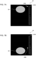
- Figs. 7A and 7B are each a diagram illustrating an example of a radiographic image 60 captured using the imaging jig 10.
- Fig. 7A illustrates a case where the moving unit 12 is positioned at the initial position
- Fig. 7B illustrates a case where the moving unit 12 is positioned at a movement position displaced from the initial position.
- an image 20AI of the mark 20A and an image 20BI of the mark 20B are depicted together with an image 50I of the imaging target 50.
- an image 20AI of the mark 20A and an image 20BI of the mark 20B are depicted together with an image 50I of the imaging target 50.
- the amount of movement of the imaging target 50 at the movement position from the initial position can be identified based on the image 20AI of the mark 20A and the image 20BI of the mark 20B when the moving unit 12 is positioned at the movement position.
- the movement amount information displayed by the mark 20A and the mark 20B indicates the amount of movement of the imaging target 50 from the initial position.
- the radiographic image generated by the radiation detector 30 is stored in an image server (not illustrated).
- Fig. 8 is a diagram illustrating an example of a hardware configuration of an information processing apparatus 100 that performs processing on a radiographic image captured using the imaging jig 10.
- the information processing apparatus 100 includes a central processing unit (CPU) 101, a random access memory (RAM) 102, a non-volatile memory 103, an input device 104, a display 105, and a network interface 106. These pieces of hardware are connected to a bus 107.
- the display 105 is, for example, a liquid crystal display or a light emitting diode (LED) display.
- the input device 104 includes, for example, a keyboard and a mouse.
- the input device 104 may include a proximity input device such as a touch panel display, a voice input device such as a microphone, and a contactless input device such as a camera or a sensor.
- the network interface 106 is an interface that allows the information processing apparatus 100 to connect, via a network, to the image server (not illustrated) in which the radiographic image is stored.
- the non-volatile memory 103 is a non-volatile storage medium such as a hard disk and a flash memory.
- the non-volatile memory 103 stores an information processing program 110 and a template pattern 120. Details of the template pattern 120 will be described below.
- the RAM 102 is a work memory for the CPU 101 to execute processing.
- the CPU 101 loads the information processing program 110 stored in the non-volatile memory 103 into the RAM 102 and executes processing in accordance with the information processing program 110.
- the CPU 101 is an example of a "processor" in the disclosed technology.
- Fig. 9 is a functional block diagram illustrating an example of a functional configuration of the information processing apparatus 100.
- the information processing apparatus 100 has an acquisition unit 131, a recognition unit 132, a recording processing unit 133, and a tomographic image generation unit 134.
- the CPU 101 executes the information processing program 110, the CPU 101 functions as the acquisition unit 131, the recognition unit 132, the recording processing unit 133, and the tomographic image generation unit 134.
- the acquisition unit 131 accesses the image server (not illustrated) and acquires a series of radiographic images of the same imaging target captured using the imaging jig 10 while the moving unit 12 is being moved. That is, a plurality of radiographic images with different relative positional relationships between the radiation source 40 and the imaging target are acquired.
- the acquisition unit 131 may directly acquire the radiographic images from the radiation detector 30 without the intervention of the image server.
- the recognition unit 132 recognizes, for each of the plurality of radiographic images acquired by the acquisition unit 131, movement amount information depicted in the radiographic image.
- the recognition unit 132 recognizes the movement amount information using the template pattern 120 recorded in the non-volatile memory 103.
- the template pattern 120 has a pattern similar to those of the image 20AI of the mark 20A and the image 20BI of the mark 20B (see Figs. 7A and 7B ) depicted in the radiographic image.
- the recognition unit 132 extracts an image portion similar to the template pattern 120 from the radiographic image.
- the recognition unit 132 identifies a scale included in the extracted area, numerical values assigned to the scale, and a pointer pointing to a position on the scale and recognizes the numerical value corresponding to the position pointed to by the pointer on the scale as movement amount information.
- the recording processing unit 133 records the movement amount information recognized by the recognition unit 132 and the corresponding radiographic image in the non-volatile memory 103 in association with each other.
- the recording processing unit 133 associates, for each of the plurality of radiographic images acquired by the acquisition unit 131, movement amount information and the radiographic image with each other, and records each of the pieces of image data of the radiographic images associated with the movement amount information (hereinafter referred to as movement-amount-information-associated image data) in the non-volatile memory 103.
- the tomographic image generation unit 134 generates a tomographic image of the imaging target using the plurality of pieces of movement-amount-information-associated image data recorded in the non-volatile memory 103.
- the tomographic image generation unit 134 generates a tomographic image using, for example, the shift-and-add method, which is one of the tomographic image reconstruction methods.
- the shift-and-add method is a method that shifts, for a series of radiographic images continuously captured while changing the relative positional relationship between a radiation source and an imaging target, each image by an appropriate amount in a scanning direction and superimposes the results to obtain a tomographic image focused on a specific cross-sectional plane.
- the tomographic image generation unit 134 calculates the shift amount of each radiographic image using the movement amount information included in the movement-amount-information-associated image data when the tomographic image generation unit 134 generates, using the shift-and-add method, a tomographic image of a cross-sectional plane designated by a user.
- Fig. 10 is a flowchart illustrating an example of a process implemented by the CPU 101 executing the information processing program 110.
- the information processing program 110 is executed when, for example, the user gives an instruction to start the process by operating the input device 104.
- step S1 the acquisition unit 131 accesses the image server (not illustrated) and acquires a series of radiographic images of the same imaging target captured using the imaging jig 10 while the moving unit 12 is being moved.
- step S2 the recognition unit 132 recognizes, for each of the plurality of radiographic images acquired in step S1, movement amount information depicted in the radiographic image using the template pattern 120 recorded in the non-volatile memory 103.
- step S3 the recording processing unit 133 records, in the non-volatile memory 103, movement-amount-information-associated image data obtained by associating the movement amount information recognized in step S2 and the corresponding radiographic image with each other.
- the recording processing unit 133 records the movement-amount-information-associated image data for each of the plurality of radiographic images acquired in step S1.
- step S4 the tomographic image generation unit 134 generates a tomographic image of the imaging target using the plurality of pieces of movement-amount-information-associated image data recorded in the non-volatile memory 103 in step S3.
- the tomographic image generation unit 134 calculates the shift amount of each radiographic image using the movement amount information included in the movement-amount-information-associated image data when the tomographic image generation unit 134 generates, using the shift-and-add method, a tomographic image of a cross-sectional plane designated by a user.
- the imaging jig 10 includes a movement mechanism that moves the position of an imaging target such that the relative positional relationship between a radiation source that emits radiation and the imaging target changes, and a display portion in which movement amount information indicating an amount of movement of the imaging target from an initial position is to be displayed.
- the movement amount information is distinguishably depicted in a radiographic image captured using the imaging jig 10.
- the information processing apparatus 100 processes the radiographic image captured using the imaging jig 10.
- the information processing apparatus 100 acquires the radiographic image and recognizes movement amount information depicted in the radiographic image.
- the information processing apparatus 100 records, in a recording medium (the non-volatile memory 103), movement-amount-information-associated image data obtained by associating the movement amount information and the radiographic image with each other.
- the information processing apparatus 100 generates a tomographic image of the imaging target using a plurality of pieces of movement-amount-information-associated image data.
- an imaging apparatus including a tomosynthesis function acquires a series of radiographic images by changing an imaging direction by robot control.
- the relative positional relationship of the imaging target depicted in the series of radiographic images can be easily calculated by cooperation with the robot control for the imaging direction.
- the imaging apparatus including the tomosynthesis function can easily obtain a tomographic image, but is expensive and is not easily accessible.
- a method for acquiring a tomographic image using an imaging apparatus that does not include the tomosynthesis function is considered.
- the imaging jig 10 allows the movement amount information to be distinguishably depicted in a radiographic image acquired using the imaging jig 10.
- the movement amount information can be used as relative positional information indicating the inter-image relative positional relationship of the imaging target depicted in each of the series of radiographic images. That is, the imaging jig 10 can support the acquisition of relative positional information and the association between a radiographic image and the relative positional information.
- Fig. 11 is a diagram illustrating an example of another display format of the movement amount information.
- the movement amount information may be displayed by a mark 20C.
- the mark 20C is provided on either the fixed unit 11 or the moving unit 12.
- the mark 20C includes a scale provided along the circumference of a circle, numerical values assigned to the scale, and a pointer that points to a position on the scale.
- the pointer rotates about the center of the circle serving as a rotational axis in conjunction with the movement of the moving unit 12. That is, the tip of the pointer moves along the scale.
- the angle of rotation of the pointer is proportional to the amount of movement of the moving unit 12 from the initial position. That is, the position pointed to by the pointer on the scale indicates the amount of movement of the moving unit 12 from the initial position.
- Examples of a mechanism for rotating the pointer in conjunction with the movement of the moving unit 12 may include a configuration that transmits the translational movement of the moving unit 12 to the pointer through a rack gear and a pinion gear.
- the scale, the numerical values, and the pointer of the mark 20C are made of a material having a relatively low transmittance to radiation. This makes it possible to depict the movement amount information in the radiographic image.
- the imaging jig 10 may have a position detection mark for detecting a display position of the movement amount information.
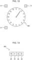
- Fig. 12 is a diagram illustrating an example of position detection marks 21 arranged around the mark 20C.
- the position detection marks 21 are depicted in the radiographic image together with the mark 20C.
- the recognition unit 132 detects the position of the mark 20C based on the position detection marks 21 included in the radiographic image, and performs image recognition on the detected mark 20C.
- Fig. 13 is a diagram illustrating an example of another display format of the movement amount information.
- the movement amount information may be displayed by a mark 20D.
- the mark 20D is provided on either the fixed unit 11 or the moving unit 12.
- the mark 20D includes numerical values of four digits.
- Each digit is marked on a rotation drum 22 having numerical values from 0 to 9 written on a peripheral surface thereof.
- the rotation drum 22 rotates, the display of the numerical value of the corresponding digit changes.
- the rotation drum 22 corresponding to each digit rotates in conjunction with the movement of the moving unit 12. That is, the amount of movement of the moving unit 12 from the initial position is indicated by numerical values of four digits constituting the mark 20D.
- the number of digits of the mark 20D can be changed as appropriate.
- Examples of a mechanism for rotating the rotation drums 22 in conjunction with the movement of the moving unit 12 may include a configuration that transmits the translational movement of the moving unit 12 to the rotation drums 22 through a rack gear and a pinion gear.
- the numerical values of the respective digits of the mark 20C are made of a material having a relatively high transmittance to radiation. This makes it possible to depict the movement amount information in the radiographic image.
- Figs. 14A and 14B are side views illustrating an example of a configuration of an imaging jig 10A according to a second embodiment of the disclosed technology and a method of using the imaging jig 10A.
- Figs. 15A and 15B are plan views corresponding to Figs. 14A and 14B , respectively.
- Figs. 14A and 15A illustrate a case where the moving unit 12 is positioned at the initial position
- Figs. 14B and 15B illustrate a case where the moving unit 12 is positioned at a movement position displaced from the initial position.
- the radiation detector 30 is disposed on top of the moving unit 12, and the imaging target 50 is placed on top of the radiation detector 30.
- the radiation source 40 which emits radiation, is disposed at a position such that the imaging target 50 is interposed between the radiation source 40 and the radiation detector 30.
- the imaging jig 10A has a mark member 23 provided at an end of the fixed unit 11 and a mark member 24 provided at an end of the moving unit 12.
- the mark member 23 has a first portion having one end connected to the fixed unit 11 and extending upward from a connection portion with the fixed unit 11 to a position higher than the height of an imaging surface of the radiation detector 30, and a second portion that protrudes from an upper end of the first portion so as to overlap with the imaging surface of the radiation detector 30.
- the mark member 24 has a first portion having one end connected to the moving unit 12 and extending upward from a connection portion with the moving unit 12 to the position higher than the height of the imaging surface of the radiation detector 30, and a second portion that protrudes from an upper end of the first portion so as to overlap with the imaging surface of the radiation detector 30.
- the relative positions of the radiation source 40, the imaging jig 10A, and the radiation detector 30 are determined such that the imaging target 50 and the mark members 23 and 24 fall within an imaging field of view.
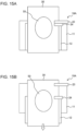
- Figs. 16A and 16B are each a diagram illustrating an example of a radiographic image 61 captured using the imaging jig 10A.
- Fig. 16A illustrates a case where the moving unit 12 is positioned at the initial position
- Fig. 16B illustrates a case where the moving unit 12 is positioned at a movement position displaced from the initial position.
- an image 23I of the mark member 23 and an image 24I of the mark member 24 are depicted together with an image 50I of the imaging target 50.
- Fig. 16A illustrates a case where the moving unit 12 is positioned at the initial position
- Fig. 16B illustrates a case where the moving unit 12 is positioned at a movement position displaced from the initial position.
- an image 23I of the mark member 23 and an image 24I of the mark member 24 are depicted together with an image 50I of the imaging target 50.
- the amount of movement of the imaging target 50 at the movement position from the initial position can be identified based on the image 23I of the mark member 23 and the image 24I of the mark member 24 when the moving unit 12 is positioned at the movement position.
- the movement amount information displayed by the mark member 23 and the mark member 24 indicates the amount of movement of the imaging target 50 from the initial position.
- the recognition unit 132 of the information processing apparatus 100 recognizes the movement amount information using the template pattern 120 recorded in the non-volatile memory 103.
- the template pattern 120 has a pattern similar to those of the image 23I of the mark member 23 and the image 24I of the mark member 24 depicted in the radiographic image.
- the recognition unit 132 extracts an image portion similar to the template pattern 120 from the radiographic image.
- the recognition unit 132 recognizes, as the movement amount information, a numerical value corresponding to the distance between the image of the mark member 23 and the image of the mark member 24 included in the extracted region.
- the imaging jig 10A can support the acquisition of relative positional information indicating the inter-image relative positional relationship of an imaging target depicted in each of a plurality of radiographic images and the association between the radiographic image and the relative positional information.
- Figs. 17A and 17B are side views illustrating an example of a configuration of an imaging jig 10B according to a third embodiment of the disclosed technology and a method of using the imaging jig 10B.
- Fig. 17A illustrates a case where the moving unit 12 is positioned at the initial position
- Fig. 17B illustrates a case where the moving unit 12 is positioned at a movement position displaced from the initial position.
- the radiation detector 30 is disposed on top of the moving unit 12, and the imaging target 50 is placed on top of the radiation detector 30.
- the radiation source 40 which emits radiation, is disposed at a position such that the imaging target 50 is interposed between the radiation source 40 and the radiation detector 30.
- the fixed unit 11 and the moving unit 12 are connected to each other through a hinge 15 at their respective ends.
- the moving unit 12 is capable of rotational movement about the hinge 15 serving as a rotational axis. That is, in the imaging jig 10B according to the present embodiment, a movement mechanism constituted by the fixed unit 11 and the moving unit 12 can rotationally move the imaging target 50. The movement of the moving unit 12 can be performed manually or automatically.
- the imaging jig 10B has a mark member 23 provided at an end of the fixed unit 11 and a mark member 24 provided at an end of the moving unit 12.
- the configurations of the mark members 23 and 24 are the same as those in the second embodiment described above, and descriptions thereof are omitted.
- a radiographic image of the imaging target 50 is captured when, as illustrated in Fig. 17A , the moving unit 12 is kept at the initial position. Thereafter, as illustrated in Fig. 17B , the moving unit 12 is rotationally moved to move the radiation detector 30 and the imaging target 50 to the movement position together with the moving unit 12. That is, the imaging jig 10B moves the position of the imaging target 50 such that the relative positional relationship between the radiation source 40 and the imaging target 50 changes.
- a radiographic image of the imaging target 50 is captured at each of a plurality of different movement positions. During the capturing of the radiographic images, the radiation source 40 and the fixed unit 11 are maintained in a stationary state.
- an image of the mark member 23 and an image of the mark member 24 are depicted together with an image of the imaging target 50.
- the amount of movement of the imaging target 50 at the movement position from the initial position can be identified based on the image of the mark member 23 and the image of the mark member 24 when the moving unit 12 is positioned at the movement position.
- the movement amount information displayed by the mark member 23 and the mark member 24 indicates the amount of movement of the imaging target 50 from the initial position.
- the imaging jig 10B can support the acquisition of relative positional information indicating the inter-image relative positional relationship of an imaging target depicted in each of a plurality of radiographic images and the association between the radiographic image and the relative positional information.
- various types of processors can be used as the hardware structure of processing units that execute various types of processing, such as the acquisition unit 131, the recognition unit 132, the recording processing unit 133, and the tomographic image generation unit 134.
- the various types of processors include, in addition to a CPU and a GPU, which are general-purpose processors that execute software (programs) to function as various types of processing units, programmable logic devices (PLDs), which are processors whose circuit configurations can be changed after manufacture, such as FPGAs, dedicated electric circuits that are processors having circuit configurations specifically designed to execute specific processing tasks, such as application specific integrated circuits (ASICs), and the like.
- PLDs programmable logic devices
- One processing unit may be configured using one of such various types of processors, or may be configured using a combination of two or more processors of the same or different types (e.g., a combination of multiple FPGAs or a combination of a CPU and an FPGA). Alternatively, multiple processing units may be configured using a single processor.
- processors may include, more specifically, an electrical circuit (circuitry) in which circuit elements such as semiconductor elements are combined.
- the information processing program 110 is described as being stored in advance (installed) in the non-volatile memory 103.
- the information processing program 110 may be provided in a form recorded on recording media such as a compact disc read only memory (CD-ROM), a digital versatile disc read only memory (DVD-ROM), and a universal serial bus (USB) memory.
- the information processing program 110 may be downloaded from an external device via a network. That is, the program (i.e., the program product) described in the present embodiment may be provided on a recording medium or may be distributed from an external computer.
- An imaging jig to be used for capturing a radiographic image of an imaging target irradiated with radiation including:
- the imaging jig according to appendix 1 or 2 in which a display of the movement amount information changes in conjunction with an operation of the movement mechanism.
- the imaging jig according to appendix 5 in which the display portion includes a first mark provided on the fixed unit and a second mark provided on the moving unit, and displays the movement amount information based on a relative positional relationship between the first mark and the second mark.
- An information processing apparatus including at least one processor, the information processing apparatus being for processing a radiographic image captured using the imaging jig according to any one of claims 1 to 6, the at least one processor being configured to:
- the information processing apparatus according to any one of appendices 7 to 9, in which the at least one processor is configured to record movement-amount-information-associated image data in a recording medium, the movement-amount-information-associated image data being obtained by associating the movement amount information and the radiographic image with each other.
- the information processing apparatus in which the at least one processor is configured to generate a tomographic image of the imaging target using a plurality of pieces of the movement-amount-information-associated data recorded in the recording medium for a plurality of radiographic images with different relative positional relationships between the radiation source and the imaging target.
- JP2022-111363 filed on July 11, 2022 is incorporated herein by reference in its entirety. All the documents, patent applications, and technical standards mentioned in this specification are incorporated herein by reference to the same extent as if each individual document, patent application, and technical standard were specifically and individually indicated to be incorporated by reference.
Landscapes
- Health & Medical Sciences (AREA)
- General Physics & Mathematics (AREA)
- Chemical & Material Sciences (AREA)
- Pathology (AREA)
- Immunology (AREA)
- Analytical Chemistry (AREA)
- Physics & Mathematics (AREA)
- Biochemistry (AREA)
- General Health & Medical Sciences (AREA)
- Life Sciences & Earth Sciences (AREA)
- Nuclear Medicine, Radiotherapy & Molecular Imaging (AREA)
- Theoretical Computer Science (AREA)
- Engineering & Computer Science (AREA)
- Radiology & Medical Imaging (AREA)
- Pulmonology (AREA)
- Apparatus For Radiation Diagnosis (AREA)
Abstract
Description
- The disclosed technology relates to an imaging jig and an information processing apparatus.
- The following techniques are known in relation to radiographic imaging. For example,
JP2018-179657A -
JP2013-15426A - Tomosynthesis is known as an imaging technique for reconstructing a cross-sectional plane at a desired depth position in a single tomographic imaging session. One generally known reconstruction processing method using tomosynthesis is a method called a shift-and-add method. The shift-and-add method is a method that shifts, for a series of radiographic images continuously captured while changing the relative positional relationship between a radiation source and an imaging target, each image by an appropriate amount in a scanning direction and superimposes the results to obtain a tomographic image focused on a specific cross-sectional plane. Adjusting the shift amount for each image makes it possible to obtain a tomographic image of any cross-sectional plane.
- In a reconstruction process of the tomographic image, to calculate the respective shift amounts of the radiographic images, information indicating the inter-image relative positional relationship (hereinafter referred to as relative positional information) of an imaging target depicted in the radiographic images is required for each image. An imaging apparatus including a tomosynthesis function acquires a series of radiographic images by changing an imaging direction by robot control. The relative positional relationship of the imaging target depicted in the series of radiographic images can be easily calculated by cooperation with the robot control for the imaging direction. The imaging apparatus including the tomosynthesis function can easily obtain a tomographic image, but is expensive and is not easily accessible.
- Accordingly, a method for acquiring a tomographic image using an imaging apparatus that does not include the tomosynthesis function (robot control function for the imaging direction) is considered. It is possible to acquire a plurality of radiographic images from different imaging directions by manually moving the position of the imaging target such that the relative positional relationship between the radiation source and the imaging target changes. In this case, however, it is not easy to acquire accurate relative positional information for each of the plurality of radiographic images from different imaging directions. In addition, it is necessary to manually associate the radiographic images with their corresponding relative positional information.
- The disclosed technology has been developed in view of the above points, and an object thereof is to support the acquisition of relative positional information and the association between a radiographic image and the relative positional information.
- An imaging jig according to the disclosed technology is an imaging jig to be used for capturing a radiographic image of an imaging target irradiated with radiation. The imaging jig includes a movement mechanism that moves a position of the imaging target such that a relative positional relationship between a radiation source that emits the radiation and the imaging target changes; and a display portion in which movement amount information indicating an amount of movement of the imaging target from an initial position is to be displayed. The movement amount information is distinguishably depicted in the radiographic image.
- The movement mechanism may translationally or rotationally move the imaging target. A display of the movement amount information may change in conjunction with an operation of the movement mechanism. The movement amount information may be displayed by a mark made of a material having a different transmittance to the radiation from a material of the movement mechanism.
- The movement mechanism may include a fixed unit having a fixed relative positional relationship with the radiation source, and a moving unit provided to be movable with respect to the fixed unit. The imaging target may move along with a movement of the moving unit. The display portion may include a first mark provided on the fixed unit and a second mark provided on the moving unit. The display portion may display the movement amount information based on a relative positional relationship between the first mark and the second mark.
- An information processing apparatus according to the disclosed technology includes at least one processor and is for processing a radiographic image captured using the above-described imagingjig. The at least one processor is configured to acquire the radiographic image and recognize movement amount information depicted in the radiographic image.
- The at least one processor may be configured to recognize the movement amount information included in the radiographic image by matching the movement amount information against a template pattern corresponding to the movement amount information.
- A position detection mark for detecting a display position of the movement amount information may be distinguishably depicted in the radiographic image. The at least one processor may be configured to detect a position of the movement amount information included in the radiographic image, based on the position detection mark included in the radiographic image.
- The at least one processor may be configured to record movement-amount-information-associated image data in a recording medium, the movement-amount-information-associated image data being obtained by associating the movement amount information and the radiographic image with each other.
- The at least one processor may be configured to generate a tomographic image of the imaging target using a plurality of pieces of the movement-amount-information-associated data recorded in the recording medium for a plurality of radiographic images with different relative positional relationships between the radiation source and the imaging target.
- According to the disclosed technology, it is possible to support the acquisition of relative positional information and the association between a radiographic image and the relative positional information.
-
-
Fig. 1 is a perspective view of an example of a configuration of an imagingjig according to an embodiment of the disclosed technology; -
Fig. 2 is an exploded perspective view of a fixed unit and a moving unit according to the embodiment of the disclosed technology; -
Fig. 3 is a perspective view illustrating a linear movement of the moving unit on the fixed unit according to the embodiment of the disclosed technology; -
Fig. 4A is a plan view of the moving unit, as viewed from the side of a contact surface with the fixed unit, according to the embodiment of the disclosed technology; -
Fig. 4B is a plan view of the fixed unit, as viewed from the side of a contact surface with the moving unit, according to the embodiment of the disclosed technology; -
Fig. 5A is a perspective view of marks when the imagingjig according to the embodiment of the disclosed technology is viewed from an upper surface side of the moving unit; -
Fig. 5B is a perspective view of the marks when the imaging jig according to the embodiment of the disclosed technology is viewed from the upper surface side of the moving unit; -
Fig. 6A is a side view illustrating an example of a method of using the imaging jig according to the embodiment of the disclosed technology; -
Fig. 6B is a side view illustrating the example of the method of using the imaging jig according to the embodiment of the disclosed technology; -
Fig. 7A is a diagram illustrating an example of a radiographic image captured using the imaging jig according to the embodiment of the disclosed technology; -
Fig. 7B is a diagram illustrating an example of a radiographic image captured using the imaging jig according to the embodiment of the disclosed technology; -
Fig. 8 is a diagram illustrating an example of a hardware configuration of an information processing apparatus according to the embodiment of the disclosed technology; -
Fig. 9 is a functional block diagram illustrating an example of a functional configuration of the information processing apparatus according to the embodiment of the disclosed technology; -
Fig. 10 is a flowchart illustrating an example of a process implemented by a CPU executing an information processing program according to the embodiment of the disclosed technology; -
Fig. 11 is a diagram illustrating an example of another display format of movement amount information according to the embodiment of the disclosed technology; -
Fig. 12 is a diagram illustrating an example of position detection marks arranged around a mark according to the embodiment of the disclosed technology; -
Fig. 13 is a diagram illustrating an example of another display format of the movement amount information according to the embodiment of the disclosed technology; -
Fig. 14A is a side view illustrating an example of a configuration of an imaging jig according to another embodiment of the disclosed technology and a method of using the imaging jig; -
Fig. 14B is a side view illustrating an example of the configuration of the imaging jig according to the other embodiment of the disclosed technology and the method of using the imaging jig; -
Fig. 15A is a plan view corresponding toFig. 14A ; -
Fig. 15B is a plan view corresponding toFig. 14B ; -
Fig. 16A is a diagram illustrating an example of a radiographic image captured using the imaging jig according to the other embodiment of the disclosed technology; -
Fig. 16B is a diagram illustrating an example of a radiographic image captured using the imaging jig according to the other embodiment of the disclosed technology; -
Fig. 17A is a side view illustrating an example of a configuration of an imaging jig according to another embodiment of the disclosed technology and a method of using the imaging jig; and -
Fig. 17B is a side view illustrating an example of the configuration of the imaging jig according to the other embodiment of the disclosed technology and the method of using the imaging jig. - Hereinafter, an example of embodiments of the disclosed technology will be described with reference to the drawings. In each drawing, identical or equivalent components and portions are designated by the same reference numerals, and redundant descriptions are omitted.
-
Fig. 1 is a perspective view of an example of a configuration of animaging jig 10 according to an embodiment of the disclosed technology. Theimaging jig 10 is a holding device to be used for capturing a radiographic image of an imaging target irradiated with radiation. Theimaging jig 10 includes a fixedunit 11 and a movingunit 12. The fixedunit 11 has a fixed relative position with respect to a radiation source (not illustrated) that emits radiation. The movingunit 12 is provided to be movable with respect to the fixedunit 11. The fixedunit 11 and the movingunit 12 are examples of a "movement mechanism" in the disclosed technology. -
Fig. 2 is an exploded perspective view of the fixedunit 11 and the movingunit 12. The movingunit 12 is provided with, in a contact surface thereof with the fixedunit 11, aguide groove 13 that extends linearly. The fixedunit 11 is provided with, on a contact surface thereof with the movingunit 12, aconvex guide rail 14 that extends linearly. As illustrated inFig. 3 , the movingunit 12 can move linearly (translationally move) on the fixedunit 11 along theguide rail 14 with theguide rail 14 fitted in theguide groove 13. That is, theimaging jig 10 functions as a so-called linear motion stage. The movement of the movingunit 12 can be performed manually or automatically. -
Fig. 4A is a plan view of the movingunit 12 as viewed from the side of the contact surface with the fixedunit 11.Fig. 4B is a plan view of the fixedunit 11 as viewed from the side of the contact surface with the movingunit 12. The contact surfaces of the fixedunit 11 and the movingunit 12 are provided withmarks unit 12 from an initial position. The portions of theimaging jig 10 where themark 20A and themark 20B are formed are examples of a "display portion" in the disclosed technology. Themark 20A is a linear scale with numerical values assigned to the scale, the scale extending along the extension direction of theguide rail 14, and is drawn on the outside of theguide rail 14. Themark 20B is a pointer pointing to a position on themark 20A (scale), and is drawn on the outside of theguide groove 13. The initial position can be determined as desired. For example, as illustrated inFig. 1 , the initial position may be set as a position where an end surface of the fixedunit 11 and an end surface of the movingunit 12 are aligned with each other in the movement direction of the movingunit 12. -
Figs. 5A and5B are perspective views of themark 20A and themark 20B when theimaging jig 10 is viewed from the upper surface side of the movingunit 12.Fig. 5A illustrates a case where the movingunit 12 is positioned at the initial position, andFig. 5B illustrates a case where the movingunit 12 is positioned at a movement position displaced from the initial position. When the movingunit 12 is positioned at the initial position, a numerical value N1 indicating a position pointed to by themark 20B (pointer) on themark 20A (scale) is typically "0". As the movingunit 12 moves from the initial position, the position pointed to by themark 20B (pointer) on themark 20A (scale) changes accordingly. A numerical value N2 indicating the position pointed to by themark 20B (pointer) on themark 20A (scale) at the movement position indicates the amount of movement of the movingunit 12 from the initial position. In other words, the display of the movement amount information by themarks unit 12. It should be noted that the numerical value N1 indicating the position pointed to by themark 20B (pointer) on themark 20A (scale) when the movingunit 12 is positioned at the initial position need not be "0". In the case where the numerical value N1 is not "0", the difference between the numerical value N2 at the movement position and the numerical value N1 at the initial position (N2 - N1) corresponds to the amount of movement of the movingunit 12. - The fixed
unit 11 and the movingunit 12 are made of a material having a relatively high transmittance to radiation (X-rays). Examples of the material of the fixedunit 11 and the movingunit 12 may include plastics such as polyethylene (PE), polypropylene (PP), polyethylene terephthalate (PET), and polystyrene (PS). In contrast, themarks unit 12 and the fixedunit 11, respectively, using a material having a relatively low transmittance to radiation (X-rays). Examples of the material of themarks marks unit 11 and the movingunit 12. Thus, the movement amount information can be depicted in a radiographic image captured using theimaging jig 10. -
Figs. 6A and 6B are side views illustrating an example of a method of using theimaging jig 10.Fig. 6A illustrates a case where the movingunit 12 is positioned at the initial position, andFig. 6B illustrates a case where the movingunit 12 is positioned at a movement position displaced from the initial position. As illustrated inFigs. 6A and 6B , animaging target 50 for a radiographic image is placed on top of the movingunit 12, and aradiation detector 30 is disposed under the fixedunit 11. Aradiation source 40 that emits radiation is disposed at a position such that theimaging jig 10 and theimaging target 50 are interposed between theradiation source 40 and theradiation detector 30. The relative positions of theradiation source 40, theimaging jig 10, and theradiation detector 30 are determined such that theimaging target 50, themark 20A, and themark 20B fall within an imaging field of view. Theradiation detector 30 may be a known flat panel detector that generates a radiographic image. - A radiographic image of the
imaging target 50 is captured when, as illustrated inFig. 6A , the movingunit 12 is kept at the initial position. Thereafter, as illustrated inFig. 6B , the movingunit 12 is translationally moved to the left in the figure to move theimaging target 50 to the movement position together with the movingunit 12. That is, theimaging jig 10 moves the position of theimaging target 50 such that the relative positional relationship between theradiation source 40 and theimaging target 50 changes. A radiographic image of theimaging target 50 is captured at each of a plurality of different movement positions. During the capturing of the radiographic images, theradiation source 40, the fixedunit 11, and theradiation detector 30 are maintained in a stationary state. -
Figs. 7A and 7B are each a diagram illustrating an example of aradiographic image 60 captured using theimaging jig 10.Fig. 7A illustrates a case where the movingunit 12 is positioned at the initial position, andFig. 7B illustrates a case where the movingunit 12 is positioned at a movement position displaced from the initial position. In theradiographic image 60, an image 20AI of themark 20A and an image 20BI of themark 20B are depicted together with an image 50I of theimaging target 50. As illustrated inFig. 7B , the amount of movement of theimaging target 50 at the movement position from the initial position can be identified based on the image 20AI of themark 20A and the image 20BI of themark 20B when the movingunit 12 is positioned at the movement position. In other words, the movement amount information displayed by themark 20A and themark 20B indicates the amount of movement of theimaging target 50 from the initial position. The radiographic image generated by theradiation detector 30 is stored in an image server (not illustrated). -
Fig. 8 is a diagram illustrating an example of a hardware configuration of aninformation processing apparatus 100 that performs processing on a radiographic image captured using theimaging jig 10. Theinformation processing apparatus 100 includes a central processing unit (CPU) 101, a random access memory (RAM) 102, anon-volatile memory 103, aninput device 104, adisplay 105, and anetwork interface 106. These pieces of hardware are connected to abus 107. - The
display 105 is, for example, a liquid crystal display or a light emitting diode (LED) display. Theinput device 104 includes, for example, a keyboard and a mouse. Theinput device 104 may include a proximity input device such as a touch panel display, a voice input device such as a microphone, and a contactless input device such as a camera or a sensor. Thenetwork interface 106 is an interface that allows theinformation processing apparatus 100 to connect, via a network, to the image server (not illustrated) in which the radiographic image is stored. - The
non-volatile memory 103 is a non-volatile storage medium such as a hard disk and a flash memory. Thenon-volatile memory 103 stores aninformation processing program 110 and atemplate pattern 120. Details of thetemplate pattern 120 will be described below. TheRAM 102 is a work memory for theCPU 101 to execute processing. TheCPU 101 loads theinformation processing program 110 stored in thenon-volatile memory 103 into theRAM 102 and executes processing in accordance with theinformation processing program 110. TheCPU 101 is an example of a "processor" in the disclosed technology. -
Fig. 9 is a functional block diagram illustrating an example of a functional configuration of theinformation processing apparatus 100. Theinformation processing apparatus 100 has anacquisition unit 131, arecognition unit 132, arecording processing unit 133, and a tomographicimage generation unit 134. When theCPU 101 executes theinformation processing program 110, theCPU 101 functions as theacquisition unit 131, therecognition unit 132, therecording processing unit 133, and the tomographicimage generation unit 134. - The
acquisition unit 131 accesses the image server (not illustrated) and acquires a series of radiographic images of the same imaging target captured using theimaging jig 10 while the movingunit 12 is being moved. That is, a plurality of radiographic images with different relative positional relationships between theradiation source 40 and the imaging target are acquired. Theacquisition unit 131 may directly acquire the radiographic images from theradiation detector 30 without the intervention of the image server. - The
recognition unit 132 recognizes, for each of the plurality of radiographic images acquired by theacquisition unit 131, movement amount information depicted in the radiographic image. Therecognition unit 132 recognizes the movement amount information using thetemplate pattern 120 recorded in thenon-volatile memory 103. Thetemplate pattern 120 has a pattern similar to those of the image 20AI of themark 20A and the image 20BI of themark 20B (seeFigs. 7A and 7B ) depicted in the radiographic image. Therecognition unit 132 extracts an image portion similar to thetemplate pattern 120 from the radiographic image. Therecognition unit 132 identifies a scale included in the extracted area, numerical values assigned to the scale, and a pointer pointing to a position on the scale and recognizes the numerical value corresponding to the position pointed to by the pointer on the scale as movement amount information. - The
recording processing unit 133 records the movement amount information recognized by therecognition unit 132 and the corresponding radiographic image in thenon-volatile memory 103 in association with each other. Therecording processing unit 133 associates, for each of the plurality of radiographic images acquired by theacquisition unit 131, movement amount information and the radiographic image with each other, and records each of the pieces of image data of the radiographic images associated with the movement amount information (hereinafter referred to as movement-amount-information-associated image data) in thenon-volatile memory 103. - The tomographic
image generation unit 134 generates a tomographic image of the imaging target using the plurality of pieces of movement-amount-information-associated image data recorded in thenon-volatile memory 103. The tomographicimage generation unit 134 generates a tomographic image using, for example, the shift-and-add method, which is one of the tomographic image reconstruction methods. The shift-and-add method is a method that shifts, for a series of radiographic images continuously captured while changing the relative positional relationship between a radiation source and an imaging target, each image by an appropriate amount in a scanning direction and superimposes the results to obtain a tomographic image focused on a specific cross-sectional plane. Adjusting the shift amount for each image makes it possible to obtain a tomographic image of any cross-sectional plane. The tomographicimage generation unit 134 calculates the shift amount of each radiographic image using the movement amount information included in the movement-amount-information-associated image data when the tomographicimage generation unit 134 generates, using the shift-and-add method, a tomographic image of a cross-sectional plane designated by a user. -
Fig. 10 is a flowchart illustrating an example of a process implemented by theCPU 101 executing theinformation processing program 110. Theinformation processing program 110 is executed when, for example, the user gives an instruction to start the process by operating theinput device 104. - In step S1, the
acquisition unit 131 accesses the image server (not illustrated) and acquires a series of radiographic images of the same imaging target captured using theimaging jig 10 while the movingunit 12 is being moved. - In step S2, the
recognition unit 132 recognizes, for each of the plurality of radiographic images acquired in step S1, movement amount information depicted in the radiographic image using thetemplate pattern 120 recorded in thenon-volatile memory 103. - In step S3, the
recording processing unit 133 records, in thenon-volatile memory 103, movement-amount-information-associated image data obtained by associating the movement amount information recognized in step S2 and the corresponding radiographic image with each other. Therecording processing unit 133 records the movement-amount-information-associated image data for each of the plurality of radiographic images acquired in step S1. - In step S4, the tomographic
image generation unit 134 generates a tomographic image of the imaging target using the plurality of pieces of movement-amount-information-associated image data recorded in thenon-volatile memory 103 in step S3. The tomographicimage generation unit 134 calculates the shift amount of each radiographic image using the movement amount information included in the movement-amount-information-associated image data when the tomographicimage generation unit 134 generates, using the shift-and-add method, a tomographic image of a cross-sectional plane designated by a user. - As described above, the
imaging jig 10 according to the embodiment of the disclosed technology includes a movement mechanism that moves the position of an imaging target such that the relative positional relationship between a radiation source that emits radiation and the imaging target changes, and a display portion in which movement amount information indicating an amount of movement of the imaging target from an initial position is to be displayed. The movement amount information is distinguishably depicted in a radiographic image captured using theimaging jig 10. - In addition, the
information processing apparatus 100 according to the embodiment of the disclosed technology processes the radiographic image captured using theimaging jig 10. Theinformation processing apparatus 100 acquires the radiographic image and recognizes movement amount information depicted in the radiographic image. Theinformation processing apparatus 100 records, in a recording medium (the non-volatile memory 103), movement-amount-information-associated image data obtained by associating the movement amount information and the radiographic image with each other. Theinformation processing apparatus 100 generates a tomographic image of the imaging target using a plurality of pieces of movement-amount-information-associated image data. - In the reconstruction process of the tomographic image, information indicating the relative positional relationship (relative positional information) of the imaging target depicted in each radiographic image is required for each image. An imaging apparatus including a tomosynthesis function acquires a series of radiographic images by changing an imaging direction by robot control. The relative positional relationship of the imaging target depicted in the series of radiographic images can be easily calculated by cooperation with the robot control for the imaging direction. The imaging apparatus including the tomosynthesis function can easily obtain a tomographic image, but is expensive and is not easily accessible.
- Accordingly, a method for acquiring a tomographic image using an imaging apparatus that does not include the tomosynthesis function (robot control function for the imaging direction) is considered. For example, it is possible to acquire a plurality of radiographic images from different imaging directions by manually moving the position of the imaging target such that the relative positional relationship between the radiation source and the imaging target changes. In this case, however, it is not easy to acquire accurate relative positional information indicating the inter-image relative positional relationship for each of the plurality of radiographic images from different imaging directions. In addition, it is necessary to manually associate the radiographic images with their corresponding relative positional information.
- The
imaging jig 10 according to the present embodiment allows the movement amount information to be distinguishably depicted in a radiographic image acquired using theimaging jig 10. The movement amount information can be used as relative positional information indicating the inter-image relative positional relationship of the imaging target depicted in each of the series of radiographic images. That is, theimaging jig 10 can support the acquisition of relative positional information and the association between a radiographic image and the relative positional information. - It should be noted that the display of the movement amount information is not limited to that using the
marks Fig. 11 is a diagram illustrating an example of another display format of the movement amount information. As illustrated inFig. 11 , the movement amount information may be displayed by a mark 20C. The mark 20C is provided on either the fixedunit 11 or the movingunit 12. The mark 20C includes a scale provided along the circumference of a circle, numerical values assigned to the scale, and a pointer that points to a position on the scale. The pointer rotates about the center of the circle serving as a rotational axis in conjunction with the movement of the movingunit 12. That is, the tip of the pointer moves along the scale. The angle of rotation of the pointer is proportional to the amount of movement of the movingunit 12 from the initial position. That is, the position pointed to by the pointer on the scale indicates the amount of movement of the movingunit 12 from the initial position. Examples of a mechanism for rotating the pointer in conjunction with the movement of the movingunit 12 may include a configuration that transmits the translational movement of the movingunit 12 to the pointer through a rack gear and a pinion gear. The scale, the numerical values, and the pointer of the mark 20C are made of a material having a relatively low transmittance to radiation. This makes it possible to depict the movement amount information in the radiographic image. - The
imaging jig 10 may have a position detection mark for detecting a display position of the movement amount information.Fig. 12 is a diagram illustrating an example of position detection marks 21 arranged around the mark 20C. The position detection marks 21 are depicted in the radiographic image together with the mark 20C. In theinformation processing apparatus 100, therecognition unit 132 detects the position of the mark 20C based on the position detection marks 21 included in the radiographic image, and performs image recognition on the detected mark 20C. -
Fig. 13 is a diagram illustrating an example of another display format of the movement amount information. As illustrated inFig. 13 , the movement amount information may be displayed by amark 20D. Themark 20D is provided on either the fixedunit 11 or the movingunit 12. Themark 20D includes numerical values of four digits. Each digit is marked on arotation drum 22 having numerical values from 0 to 9 written on a peripheral surface thereof. As therotation drum 22 rotates, the display of the numerical value of the corresponding digit changes. Therotation drum 22 corresponding to each digit rotates in conjunction with the movement of the movingunit 12. That is, the amount of movement of the movingunit 12 from the initial position is indicated by numerical values of four digits constituting themark 20D. The number of digits of themark 20D can be changed as appropriate. Examples of a mechanism for rotating the rotation drums 22 in conjunction with the movement of the movingunit 12 may include a configuration that transmits the translational movement of the movingunit 12 to the rotation drums 22 through a rack gear and a pinion gear. The numerical values of the respective digits of the mark 20C are made of a material having a relatively high transmittance to radiation. This makes it possible to depict the movement amount information in the radiographic image. -
Figs. 14A and 14B are side views illustrating an example of a configuration of animaging jig 10A according to a second embodiment of the disclosed technology and a method of using theimaging jig 10A.Figs. 15A and 15B are plan views corresponding toFigs. 14A and 14B , respectively.Figs. 14A and15A illustrate a case where the movingunit 12 is positioned at the initial position, andFigs. 14B and15B illustrate a case where the movingunit 12 is positioned at a movement position displaced from the initial position. Theradiation detector 30 is disposed on top of the movingunit 12, and theimaging target 50 is placed on top of theradiation detector 30. Theradiation source 40, which emits radiation, is disposed at a position such that theimaging target 50 is interposed between theradiation source 40 and theradiation detector 30. - The
imaging jig 10A has amark member 23 provided at an end of the fixedunit 11 and amark member 24 provided at an end of the movingunit 12. Themark member 23 has a first portion having one end connected to the fixedunit 11 and extending upward from a connection portion with the fixedunit 11 to a position higher than the height of an imaging surface of theradiation detector 30, and a second portion that protrudes from an upper end of the first portion so as to overlap with the imaging surface of theradiation detector 30. Likewise, themark member 24 has a first portion having one end connected to the movingunit 12 and extending upward from a connection portion with the movingunit 12 to the position higher than the height of the imaging surface of theradiation detector 30, and a second portion that protrudes from an upper end of the first portion so as to overlap with the imaging surface of theradiation detector 30. The relative positions of theradiation source 40, theimaging jig 10A, and theradiation detector 30 are determined such that theimaging target 50 and themark members - A radiographic image of the
imaging target 50 is captured when, as illustrated inFigs. 14A and15A , the movingunit 12 is kept at the initial position. Thereafter, as illustrated inFigs. 14B and15B , the movingunit 12 is translationally moved to the left in the figures to move theradiation detector 30 and theimaging target 50 to the movement position together with the movingunit 12. That is, theimaging jig 10A moves the position of theimaging target 50 such that the relative positional relationship between theradiation source 40 and theimaging target 50 changes. A radiographic image of theimaging target 50 is captured at each of a plurality of different movement positions. During the capturing of the radiographic images, theradiation source 40 and the fixedunit 11 are maintained in a stationary state. -
Figs. 16A and 16B are each a diagram illustrating an example of aradiographic image 61 captured using theimaging jig 10A.Fig. 16A illustrates a case where the movingunit 12 is positioned at the initial position, andFig. 16B illustrates a case where the movingunit 12 is positioned at a movement position displaced from the initial position. In theradiographic image 61, an image 23I of themark member 23 and an image 24I of themark member 24 are depicted together with an image 50I of theimaging target 50. As illustrated inFig. 16B , the amount of movement of theimaging target 50 at the movement position from the initial position can be identified based on the image 23I of themark member 23 and the image 24I of themark member 24 when the movingunit 12 is positioned at the movement position. In other words, the movement amount information displayed by themark member 23 and themark member 24 indicates the amount of movement of theimaging target 50 from the initial position. - In the present embodiment, the
recognition unit 132 of theinformation processing apparatus 100 recognizes the movement amount information using thetemplate pattern 120 recorded in thenon-volatile memory 103. Thetemplate pattern 120 has a pattern similar to those of the image 23I of themark member 23 and the image 24I of themark member 24 depicted in the radiographic image. Therecognition unit 132 extracts an image portion similar to thetemplate pattern 120 from the radiographic image. Therecognition unit 132 recognizes, as the movement amount information, a numerical value corresponding to the distance between the image of themark member 23 and the image of themark member 24 included in the extracted region. - Like the
imaging jig 10 according to the first embodiment, theimaging jig 10A according to the present embodiment can support the acquisition of relative positional information indicating the inter-image relative positional relationship of an imaging target depicted in each of a plurality of radiographic images and the association between the radiographic image and the relative positional information. -
Figs. 17A and 17B are side views illustrating an example of a configuration of animaging jig 10B according to a third embodiment of the disclosed technology and a method of using theimaging jig 10B.Fig. 17A illustrates a case where the movingunit 12 is positioned at the initial position, andFig. 17B illustrates a case where the movingunit 12 is positioned at a movement position displaced from the initial position. Theradiation detector 30 is disposed on top of the movingunit 12, and theimaging target 50 is placed on top of theradiation detector 30. Theradiation source 40, which emits radiation, is disposed at a position such that theimaging target 50 is interposed between theradiation source 40 and theradiation detector 30. - In the present embodiment, the fixed
unit 11 and the movingunit 12 are connected to each other through ahinge 15 at their respective ends. The movingunit 12 is capable of rotational movement about thehinge 15 serving as a rotational axis. That is, in theimaging jig 10B according to the present embodiment, a movement mechanism constituted by the fixedunit 11 and the movingunit 12 can rotationally move theimaging target 50. The movement of the movingunit 12 can be performed manually or automatically. - The
imaging jig 10B has amark member 23 provided at an end of the fixedunit 11 and amark member 24 provided at an end of the movingunit 12. The configurations of themark members - A radiographic image of the
imaging target 50 is captured when, as illustrated inFig. 17A , the movingunit 12 is kept at the initial position. Thereafter, as illustrated inFig. 17B , the movingunit 12 is rotationally moved to move theradiation detector 30 and theimaging target 50 to the movement position together with the movingunit 12. That is, theimaging jig 10B moves the position of theimaging target 50 such that the relative positional relationship between theradiation source 40 and theimaging target 50 changes. A radiographic image of theimaging target 50 is captured at each of a plurality of different movement positions. During the capturing of the radiographic images, theradiation source 40 and the fixedunit 11 are maintained in a stationary state. - In the radiographic images, an image of the
mark member 23 and an image of themark member 24 are depicted together with an image of theimaging target 50. The amount of movement of theimaging target 50 at the movement position from the initial position can be identified based on the image of themark member 23 and the image of themark member 24 when the movingunit 12 is positioned at the movement position. In other words, the movement amount information displayed by themark member 23 and themark member 24 indicates the amount of movement of theimaging target 50 from the initial position. - Like the imaging jig according to the first embodiment, the
imaging jig 10B according to the present embodiment can support the acquisition of relative positional information indicating the inter-image relative positional relationship of an imaging target depicted in each of a plurality of radiographic images and the association between the radiographic image and the relative positional information. - In the embodiments described above, for example, various types of processors provided below can be used as the hardware structure of processing units that execute various types of processing, such as the
acquisition unit 131, therecognition unit 132, therecording processing unit 133, and the tomographicimage generation unit 134. As described above, the various types of processors include, in addition to a CPU and a GPU, which are general-purpose processors that execute software (programs) to function as various types of processing units, programmable logic devices (PLDs), which are processors whose circuit configurations can be changed after manufacture, such as FPGAs, dedicated electric circuits that are processors having circuit configurations specifically designed to execute specific processing tasks, such as application specific integrated circuits (ASICs), and the like. - One processing unit may be configured using one of such various types of processors, or may be configured using a combination of two or more processors of the same or different types (e.g., a combination of multiple FPGAs or a combination of a CPU and an FPGA). Alternatively, multiple processing units may be configured using a single processor.
- Examples of configuring multiple processing units using a single processor include, first, a form in which, as represented by computers such as client and server computers, one processor is configured using a combination of one or more CPUs and software and this processor functions as multiple processing units. The examples include, second, a form in which, as represented by a system on chip (SoC) or the like, a processor is used that implements the functions of an entire system including multiple processing units on a single integrated circuit (IC) chip. As described above, various types of processing units are configured using one or more of the above-described various types of processors as a hardware structure.
- Further, the hardware structures of the above various types of processors may include, more specifically, an electrical circuit (circuitry) in which circuit elements such as semiconductor elements are combined.
- In the embodiments described above, the
information processing program 110 is described as being stored in advance (installed) in thenon-volatile memory 103. However, the embodiments are not limited to this configuration. Theinformation processing program 110 may be provided in a form recorded on recording media such as a compact disc read only memory (CD-ROM), a digital versatile disc read only memory (DVD-ROM), and a universal serial bus (USB) memory. Alternatively, theinformation processing program 110 may be downloaded from an external device via a network. That is, the program (i.e., the program product) described in the present embodiment may be provided on a recording medium or may be distributed from an external computer. - In relation to the first to third embodiments described above, the following appendices are further disclosed.
- An imaging jig to be used for capturing a radiographic image of an imaging target irradiated with radiation, the imaging jig including:
- a movement mechanism that moves a position of the imaging target such that a relative positional relationship between a radiation source that emits the radiation and the imaging target changes; and
- a display portion in which movement amount information indicating an amount of movement of the imaging target from an initial position is to be displayed, wherein
- the movement amount information is distinguishably depicted in the radiographic image.
- The imaging jig according to
appendix 1, in which
the movement mechanism translationally or rotationally moves the imaging target. - The imaging jig according to
appendix
a display of the movement amount information changes in conjunction with an operation of the movement mechanism. - The imaging jig according to
appendix 1, in which
the movement amount information is displayed by a mark made of a material having a lower transmittance to the radiation than a material of the movement mechanism. - The imaging jig according to any one of
appendices 1 to 4, in which - the movement mechanism includes
- a fixed unit having a fixed relative positional relationship with the radiation source, and
- a moving unit provided to be movable with respect to the fixed unit, and
- the imaging target moves along with a movement of the moving unit.
- The imaging jig according to
appendix 5, in which
the display portion includes a first mark provided on the fixed unit and a second mark provided on the moving unit, and displays the movement amount information based on a relative positional relationship between the first mark and the second mark. - An information processing apparatus including at least one processor, the information processing apparatus being for processing a radiographic image captured using the imaging jig according to any one of
claims 1 to 6,
the at least one processor being configured to: - acquire the radiographic image; and
- recognize movement amount information depicted in the radiographic image.
- The information processing apparatus according to
appendix 7, in which - the at least one processor is configured to
- recognize the movement amount information included in the radiographic image by matching the movement amount information against a template pattern corresponding to the movement amount information.
- The information processing apparatus according to
appendix - a position detection mark for detecting a display position of the movement amount information is distinguishably depicted in the radiographic image, and
- the at least one processor is configured to detect a position of the movement amount information included in the radiographic image, based on the position detection mark included in the radiographic image.
- The information processing apparatus according to any one of
appendices 7 to 9, in which
the at least one processor is configured to record movement-amount-information-associated image data in a recording medium, the movement-amount-information-associated image data being obtained by associating the movement amount information and the radiographic image with each other. - The information processing apparatus according to
appendix 10, in which
the at least one processor is configured to generate a tomographic image of the imaging target using a plurality of pieces of the movement-amount-information-associated data recorded in the recording medium for a plurality of radiographic images with different relative positional relationships between the radiation source and the imaging target. - The disclosure of
JP2022-111363 filed on July 11, 2022
Claims (11)
- An imaging jig to be used for capturing a radiographic image of an imaging target irradiated with radiation, the imaging jig comprising:a movement mechanism that moves a position of the imaging target such that a relative positional relationship between a radiation source that emits the radiation and the imaging target changes; anda display portion in which movement amount information indicating an amount of movement of the imaging target from an initial position is to be displayed, whereinthe movement amount information is distinguishably depicted in the radiographic image.
- The imaging jig according to claim 1, wherein
the movement mechanism translationally or rotationally moves the imaging target. - The imaging jig according to claim 1, wherein
a display of the movement amount information changes in conjunction with an operation of the movement mechanism. - The imaging jig according to claim 1, wherein
the movement amount information is displayed by a mark made of a material having a lower transmittance to the radiation than a material of the movement mechanism. - The imaging jig according to claim 1, whereinthe movement mechanism includesa fixed unit having a fixed relative positional relationship with the radiation source, anda moving unit provided to be movable with respect to the fixed unit, andthe imaging target moves along with a movement of the moving unit.
- The imaging jig according to claim 5, wherein
the display portion includes a first mark provided on the fixed unit and a second mark provided on the moving unit, and displays the movement amount information based on a relative positional relationship between the first mark and the second mark. - An information processing apparatus comprising at least one processor, the information processing apparatus being for processing a radiographic image captured using the imaging jig according to any one of claims 1 to 6,
the at least one processor being configured to:acquire the radiographic image; andrecognize movement amount information depicted in the radiographic image. - The information processing apparatus according to claim 7, whereinthe at least one processor is configured torecognize the movement amount information included in the radiographic image by matching the movement amount information against a template pattern corresponding to the movement amount information.
- The information processing apparatus according to claim 7, whereina position detection mark for detecting a display position of the movement amount information is distinguishably depicted in the radiographic image, andthe at least one processor is configured to detect a position of the movement amount information included in the radiographic image, based on the position detection mark included in the radiographic image.
- The information processing apparatus according to claim 7, wherein
the at least one processor is configured to record movement-amount-information-associated image data in a recording medium, the movement-amount-information-associated image data being obtained by associating the movement amount information and the radiographic image with each other. - The information processing apparatus according to claim 10, wherein
the at least one processor is configured to generate a tomographic image of the imaging target using a plurality of pieces of the movement-amount-information-associated data recorded in the recording medium for a plurality of radiographic images with different relative positional relationships between the radiation source and the imaging target.
Applications Claiming Priority (2)
| Application Number | Priority Date | Filing Date | Title |
|---|---|---|---|
| JP2022111363 | 2022-07-11 | ||
| PCT/JP2023/020718 WO2024014178A1 (en) | 2022-07-11 | 2023-06-02 | Photography jig and information processing device |
Publications (2)
| Publication Number | Publication Date |
|---|---|
| EP4556897A1 true EP4556897A1 (en) | 2025-05-21 |
| EP4556897A4 EP4556897A4 (en) | 2025-11-05 |
Family
ID=89536618
Family Applications (1)
| Application Number | Title | Priority Date | Filing Date |
|---|---|---|---|
| EP23839354.0A Pending EP4556897A4 (en) | 2022-07-11 | 2023-06-02 | PHOTOGRAPHIC HOLDING DEVICE AND INFORMATION PROCESSING DEVICE |
Country Status (5)
| Country | Link |
|---|---|
| US (1) | US20250102450A1 (en) |
| EP (1) | EP4556897A4 (en) |
| JP (1) | JPWO2024014178A1 (en) |
| CN (1) | CN119404096A (en) |
| WO (1) | WO2024014178A1 (en) |
Family Cites Families (10)
| Publication number | Priority date | Publication date | Assignee | Title |
|---|---|---|---|---|
| JP2004275362A (en) * | 2003-03-14 | 2004-10-07 | Fuji Photo Film Co Ltd | Method of calculating actual size of image, method of measuring image and method of outputting image, and device thereof |
| JP5462447B2 (en) * | 2008-05-09 | 2014-04-02 | 株式会社東芝 | X-ray CT system |
| JP2013015426A (en) | 2011-07-05 | 2013-01-24 | Shimadzu Corp | Radiation ct system |
| CN105203571B (en) * | 2015-10-14 | 2018-07-24 | 临沂正大检测技术有限公司 | Small diameter tube circumferential welded seam ray detection ray machine positioning device and its operating method |
| DE112017000657A5 (en) * | 2016-02-04 | 2018-10-31 | Yxlon International Gmbh | METHOD OF RECONSTRUCTING A TEST OBJECT IN AN X-RAY CT PROCEDURE IN AN X-RAY CT SYSTEM WITHOUT A MANIPULATOR |
| JP6884625B2 (en) | 2017-04-07 | 2021-06-09 | 東芝Itコントロールシステム株式会社 | X-ray inspection equipment |
| CN207816860U (en) * | 2018-02-07 | 2018-09-04 | 东方电气集团东方锅炉股份有限公司 | Focusing mechanism for ray detection |
| CN109975333B (en) * | 2019-03-28 | 2024-05-24 | 东方电气集团东方锅炉股份有限公司 | Container girth weld ray detection device and method |
| JP7106608B2 (en) * | 2020-08-26 | 2022-07-26 | キヤノントッキ株式会社 | Mark detection device, alignment device, film formation device, mark detection method, and film formation method |
| JP7090138B2 (en) | 2020-11-13 | 2022-06-23 | 株式会社バンダイ | Arm structure and humanoid toys |
-
2023
- 2023-06-02 EP EP23839354.0A patent/EP4556897A4/en active Pending
- 2023-06-02 WO PCT/JP2023/020718 patent/WO2024014178A1/en not_active Ceased
- 2023-06-02 JP JP2024533568A patent/JPWO2024014178A1/ja active Pending
- 2023-06-02 CN CN202380048089.6A patent/CN119404096A/en active Pending
-
2024
- 2024-12-10 US US18/974,787 patent/US20250102450A1/en active Pending
Also Published As
| Publication number | Publication date |
|---|---|
| JPWO2024014178A1 (en) | 2024-01-18 |
| WO2024014178A1 (en) | 2024-01-18 |
| EP4556897A4 (en) | 2025-11-05 |
| US20250102450A1 (en) | 2025-03-27 |
| CN119404096A (en) | 2025-02-07 |
Similar Documents
| Publication | Publication Date | Title |
|---|---|---|
| US7386090B2 (en) | Processes and a device for determining the actual position of a structure of an object to be examined | |
| JP2023010939A (en) | Radiation image display device and radiographic system | |
| EP3690428A1 (en) | Inspection position specification method, three-dimensional image generation method, and inspection device | |
| CN110895812A (en) | CT image detection method and device, storage medium and electronic equipment | |
| US10888285B2 (en) | Imaging system magnification stand | |
| US11534121B2 (en) | Information processing apparatus, information processing method, and information processing program | |
| EP4556897A1 (en) | Photography jig and information processing device | |
| US20210210196A1 (en) | Medical image display device, method, and program | |
| EP4066744B1 (en) | Image processing device, image processing method, and image processing program | |
| Pandey et al. | Validating YOLOv8 and SAM Foundation Models for Robust Point-of-Care Ultrasound Aorta Segmentation | |
| JP5175916B2 (en) | Parts search system | |
| JP3765530B2 (en) | X-ray measuring method and X-ray apparatus | |
| EP4223224B1 (en) | Image-processing device, image-processing method, and image-processing program | |
| JP2004271316A (en) | X-ray CT system | |
| JP7177010B2 (en) | Radiation imaging system and transmitter | |
| EP4524891A1 (en) | Image processing apparatus, radiography system, and program | |
| EP4528651A1 (en) | Image processing apparatus, radiography system, and program | |
| US12112479B2 (en) | Image processing device, image processing method, and image processing program | |
| CN115334974A (en) | Information processing apparatus, information processing method, and information processing program | |
| JP2004333310A (en) | X-ray tomographic imaging device | |
| US10801977B2 (en) | Radiation analyzing apparatus and radiation analyzing method | |
| US11954858B2 (en) | Information processing apparatus, information processing method, and information processing program | |
| JP7781691B2 (en) | Control device, image acquisition device, control method, and control program | |
| JP7732271B2 (en) | Image processing device, display control method and program | |
| EP4545951A1 (en) | Display control device, display control method, and display control program |
Legal Events
| Date | Code | Title | Description |
|---|---|---|---|
| STAA | Information on the status of an ep patent application or granted ep patent |
Free format text: STATUS: THE INTERNATIONAL PUBLICATION HAS BEEN MADE |
|
| PUAI | Public reference made under article 153(3) epc to a published international application that has entered the european phase |
Free format text: ORIGINAL CODE: 0009012 |
|
| STAA | Information on the status of an ep patent application or granted ep patent |
Free format text: STATUS: REQUEST FOR EXAMINATION WAS MADE |
|
| 17P | Request for examination filed |
Effective date: 20250110 |
|
| AK | Designated contracting states |
Kind code of ref document: A1 Designated state(s): AL AT BE BG CH CY CZ DE DK EE ES FI FR GB GR HR HU IE IS IT LI LT LU LV MC ME MK MT NL NO PL PT RO RS SE SI SK SM TR |
|
| DAV | Request for validation of the european patent (deleted) | ||
| DAX | Request for extension of the european patent (deleted) | ||
| A4 | Supplementary search report drawn up and despatched |
Effective date: 20251002 |
|
| RIC1 | Information provided on ipc code assigned before grant |
Ipc: G01N 23/04 20180101AFI20250926BHEP |