EP4556770A1 - Fuel pump - Google Patents
Fuel pump Download PDFInfo
- Publication number
- EP4556770A1 EP4556770A1 EP22962679.1A EP22962679A EP4556770A1 EP 4556770 A1 EP4556770 A1 EP 4556770A1 EP 22962679 A EP22962679 A EP 22962679A EP 4556770 A1 EP4556770 A1 EP 4556770A1
- Authority
- EP
- European Patent Office
- Prior art keywords
- valve
- gap
- fuel
- intake valve
- electromagnetic
- Prior art date
- Legal status (The legal status is an assumption and is not a legal conclusion. Google has not performed a legal analysis and makes no representation as to the accuracy of the status listed.)
- Pending
Links
Images




Classifications
-
- F—MECHANICAL ENGINEERING; LIGHTING; HEATING; WEAPONS; BLASTING
- F02—COMBUSTION ENGINES; HOT-GAS OR COMBUSTION-PRODUCT ENGINE PLANTS
- F02M—SUPPLYING COMBUSTION ENGINES IN GENERAL WITH COMBUSTIBLE MIXTURES OR CONSTITUENTS THEREOF
- F02M59/00—Pumps specially adapted for fuel-injection and not provided for in groups F02M39/00 -F02M57/00, e.g. rotary cylinder-block type of pumps
- F02M59/44—Details, components parts, or accessories not provided for in, or of interest apart from, the apparatus of groups F02M59/02 - F02M59/42; Pumps having transducers, e.g. to measure displacement of pump rack or piston
- F02M59/46—Valves
- F02M59/466—Electrically operated valves, e.g. using electromagnetic or piezoelectric operating means
-
- F—MECHANICAL ENGINEERING; LIGHTING; HEATING; WEAPONS; BLASTING
- F02—COMBUSTION ENGINES; HOT-GAS OR COMBUSTION-PRODUCT ENGINE PLANTS
- F02M—SUPPLYING COMBUSTION ENGINES IN GENERAL WITH COMBUSTIBLE MIXTURES OR CONSTITUENTS THEREOF
- F02M59/00—Pumps specially adapted for fuel-injection and not provided for in groups F02M39/00 -F02M57/00, e.g. rotary cylinder-block type of pumps
- F02M59/20—Varying fuel delivery in quantity or timing
- F02M59/36—Varying fuel delivery in quantity or timing by variably-timed valves controlling fuel passages to pumping elements or overflow passages
- F02M59/366—Valves being actuated electrically
- F02M59/368—Pump inlet valves being closed when actuated
-
- F—MECHANICAL ENGINEERING; LIGHTING; HEATING; WEAPONS; BLASTING
- F02—COMBUSTION ENGINES; HOT-GAS OR COMBUSTION-PRODUCT ENGINE PLANTS
- F02M—SUPPLYING COMBUSTION ENGINES IN GENERAL WITH COMBUSTIBLE MIXTURES OR CONSTITUENTS THEREOF
- F02M59/00—Pumps specially adapted for fuel-injection and not provided for in groups F02M39/00 -F02M57/00, e.g. rotary cylinder-block type of pumps
- F02M59/20—Varying fuel delivery in quantity or timing
- F02M59/36—Varying fuel delivery in quantity or timing by variably-timed valves controlling fuel passages to pumping elements or overflow passages
- F02M59/366—Valves being actuated electrically
-
- F—MECHANICAL ENGINEERING; LIGHTING; HEATING; WEAPONS; BLASTING
- F04—POSITIVE - DISPLACEMENT MACHINES FOR LIQUIDS; PUMPS FOR LIQUIDS OR ELASTIC FLUIDS
- F04B—POSITIVE-DISPLACEMENT MACHINES FOR LIQUIDS; PUMPS
- F04B17/00—Pumps characterised by combination with, or adaptation to, specific driving engines or motors
- F04B17/03—Pumps characterised by combination with, or adaptation to, specific driving engines or motors driven by electric motors
- F04B17/04—Pumps characterised by combination with, or adaptation to, specific driving engines or motors driven by electric motors using solenoids
-
- F—MECHANICAL ENGINEERING; LIGHTING; HEATING; WEAPONS; BLASTING
- F16—ENGINEERING ELEMENTS AND UNITS; GENERAL MEASURES FOR PRODUCING AND MAINTAINING EFFECTIVE FUNCTIONING OF MACHINES OR INSTALLATIONS; THERMAL INSULATION IN GENERAL
- F16K—VALVES; TAPS; COCKS; ACTUATING-FLOATS; DEVICES FOR VENTING OR AERATING
- F16K31/00—Actuating devices; Operating means; Releasing devices
- F16K31/02—Actuating devices; Operating means; Releasing devices electric; magnetic
- F16K31/06—Actuating devices; Operating means; Releasing devices electric; magnetic using a magnet, e.g. diaphragm valves, cutting off by means of a liquid
- F16K31/0675—Electromagnet aspects, e.g. electric supply therefor
-
- F—MECHANICAL ENGINEERING; LIGHTING; HEATING; WEAPONS; BLASTING
- F16—ENGINEERING ELEMENTS AND UNITS; GENERAL MEASURES FOR PRODUCING AND MAINTAINING EFFECTIVE FUNCTIONING OF MACHINES OR INSTALLATIONS; THERMAL INSULATION IN GENERAL
- F16K—VALVES; TAPS; COCKS; ACTUATING-FLOATS; DEVICES FOR VENTING OR AERATING
- F16K31/00—Actuating devices; Operating means; Releasing devices
- F16K31/02—Actuating devices; Operating means; Releasing devices electric; magnetic
- F16K31/06—Actuating devices; Operating means; Releasing devices electric; magnetic using a magnet, e.g. diaphragm valves, cutting off by means of a liquid
- F16K31/0686—Braking, pressure equilibration, shock absorbing
- F16K31/0689—Braking of the valve element
-
- F—MECHANICAL ENGINEERING; LIGHTING; HEATING; WEAPONS; BLASTING
- F02—COMBUSTION ENGINES; HOT-GAS OR COMBUSTION-PRODUCT ENGINE PLANTS
- F02M—SUPPLYING COMBUSTION ENGINES IN GENERAL WITH COMBUSTIBLE MIXTURES OR CONSTITUENTS THEREOF
- F02M2200/00—Details of fuel-injection apparatus, not otherwise provided for
- F02M2200/08—Fuel-injection apparatus having special means for influencing magnetic flux, e.g. for shielding or guiding magnetic flux
-
- F—MECHANICAL ENGINEERING; LIGHTING; HEATING; WEAPONS; BLASTING
- F02—COMBUSTION ENGINES; HOT-GAS OR COMBUSTION-PRODUCT ENGINE PLANTS
- F02M—SUPPLYING COMBUSTION ENGINES IN GENERAL WITH COMBUSTIBLE MIXTURES OR CONSTITUENTS THEREOF
- F02M2200/00—Details of fuel-injection apparatus, not otherwise provided for
- F02M2200/90—Selection of particular materials
- F02M2200/9053—Metals
- F02M2200/9069—Non-magnetic metals
Definitions
- the present invention relates to a fuel pump.
- a fuel pump including an electromagnetic intake valve that discharges fuel of a desired flow rate by increasing the pressure of the fuel is widely used (see, for example, PTL 1).
- the fuel pump described in PTL 1 includes a pump body, a cylinder forming a pressurization chamber, a plunger slidably held by the cylinder, and a discharge valve mechanism, in addition to an intake valve portion constituting an electromagnetic intake valve, a magnetic circuit configuration portion, and a coil winding portion.
- the magnetic circuit configuration portion and the coil winding portion which are parts of the electromagnetic intake valve, are disposed in a state of protruding outward from the pump body. Therefore, for example, when a traffic accident involving a collision of an automobile or the like occurs, a solenoid mechanism portion and a coil portion are applied with an impact force (impact load).
- impact load an impact force
- the magnitude of the impact force is assumed in advance by a collision test, simulation, or the like, and the dimension of each part of the fuel pump are set based on this assumption.
- An object of the present invention is to provide a fuel pump that can effectively suppress occurrence of damage to components of an electromagnetic intake valve even when an impact force is applied to a coil winding portion and a magnetic circuit configuration portion constituting the electromagnetic intake valve.
- the present application includes a plurality of means for solving the above problem, and one of them is a fuel pump including an electromagnetic intake valve including a coil winding portion formed by winding an electromagnetic coil around a bobbin and a magnetic circuit configuration portion constituting a magnetic circuit when a current flows through the electromagnetic coil.
- the magnetic circuit configuration portion includes a yoke disposed so as to surround the coil winding portion, and a predetermined part facing, across a gap, the coil winding portion in a radial direction of the electromagnetic intake valve.
- the dimension of the gap is set such that the coil winding portion and the predetermined part come into contact with each other first when an impact force directed from an outer side to an inner side in the radial direction of the electromagnetic intake valve is applied to the yoke or the coil winding portion.
- the present invention it is possible to effectively suppress occurrence of damage to components of an electromagnetic intake valve even when an impact force is applied to a coil winding portion and a magnetic circuit configuration portion constituting the electromagnetic intake valve.
- FIG. 1 is an overall configuration diagram of a fuel supply system using a fuel pump according to the present embodiment.
- the fuel supply system includes a high-pressure fuel supply pump 100 as a fuel pump, an engine control unit (ECU) 101, a fuel tank 103, a common rail 106, and a plurality of injectors 107.
- the components of the high-pressure fuel supply pump 100 are integrally incorporated in a pump body 1.
- Fuel is stored in the fuel tank 103.
- the fuel in the fuel tank 103 is pumped up by a feed pump 102.
- the feed pump 102 pumps up fuel by being driven based on a signal sent from the ECU 101 to the feed pump 102.
- the fuel pumped up by the feed pump 102 is pressurized to an appropriate pressure by a pressure regulator not illustrated, and is sent to a low-pressure fuel intake port 51 of the high-pressure fuel supply pump 100 through a low-pressure pipe 104.
- the high-pressure fuel supply pump 100 pressurizes and pumps, to the common rail 106, the fuel supplied from the fuel tank 103 by driving of the feed pump 102.
- the common rail 106 is mounted with a fuel pressure sensor 105 and the plurality of injectors 107.
- the fuel pressure sensor 105 detects the pressure of fuel and outputs the detected pressure data to the ECU 101.
- the ECU 101 calculates an appropriate injection fuel amount (target injection fuel length), an appropriate fuel pressure (target fuel pressure), and the like based on engine state quantities (e.g., a crank rotation angle, a throttle opening, an engine speed, a fuel pressure, and the like) obtained from various sensors.
- the plurality of injectors 107 are mounted in accordance with the number of cylinders (combustion chambers), and inject fuel according to a drive current output from the ECU 101.
- the fuel supply system of the present embodiment is what is called a direct injection engine system in which the injectors 107 directly inject fuel into a cylinder of the engine.
- the ECU 101 controls driving of the high-pressure fuel supply pump 100 and the plurality of injectors 107 based on a calculation result such as fuel pressure (target fuel pressure). That is, the ECU 101 has a function as a pump control unit that controls the high-pressure fuel supply pump 100 and a function as an injector control unit that controls the injectors 107.
- the high-pressure fuel supply pump 100 includes a pressure pulsation reduction mechanism 9, an electromagnetic intake valve 3, which is a variable capacity mechanism, a relief valve 4 ( FIG. 2 ), and a discharge valve 8.
- the fuel flowing in from the low-pressure fuel intake port 51 reaches an intake port 31b of the electromagnetic intake valve 3 through the pressure pulsation reduction mechanism 9 and an intake passage 10b.
- the fuel flowing into the electromagnetic intake valve 3 passes through a valve portion 32 and then flows into a pressurization chamber 11 through an intake passage 1d formed at the pump body 1.
- a plunger 2 is reciprocably inserted into the pressurization chamber 11. Power is transmitted to the plunger 2 by a cam 91 ( FIG. 2 ) of the engine, and the plunger 2 reciprocates.
- the pressurization chamber 11 fuel is taken in from the electromagnetic intake valve 3 in a downward stroke of the plunger 2, and the fuel is pressurized in an upward stroke.
- the discharge valve 8 is opened.
- the high-pressure fuel is sent to the common rail 106 through a discharge passage 12a.
- the fuel discharge by the high-pressure fuel supply pump 100 is operated by opening and closing of the electromagnetic intake valve 3.
- the opening and closing of the electromagnetic intake valve 3 is controlled by the ECU 101.
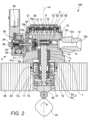
- FIG. 2 is a longitudinal cross-sectional view of the high-pressure fuel supply pump taken along the II-II position of FIG. 4 .
- FIG. 3 is a longitudinal cross-sectional view of the high-pressure fuel supply pump taken along the III-III position of FIG. 4.
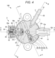
- FIG. 4 is a transverse cross-sectional view of the high-pressure fuel supply pump taken parallel to a horizontal plane.
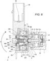
- FIG. 5 is a longitudinal cross-sectional view of the high-pressure fuel supply pump taken along the V-V position of FIG. 4 .
- the pump body 1 of the high-pressure fuel supply pump 100 is formed in a substantially columnar shape. As illustrated in FIGS. 2 and 3 , a first chamber 1a, a second chamber 1b, a third chamber 1c, and the intake passage 1d ( FIG. 2 ) are provided inside the pump body 1.
- the pump body 1 is in close contact with a fuel pump attachment portion 90, and is fixed to the fuel pump attachment portion 90 by a plurality of bolts or screws not illustrated.
- the fuel pump attachment portion 90 is a part attached with the high-pressure fuel supply pump 100.
- the first chamber 1a is a columnar space portion provided in the pump body 1.
- a center line 1A of the first chamber 1a coincides with the center line of the pump body 1.
- One end portion of the plunger 2 is inserted into the first chamber 1a.
- the plunger 2 reciprocates in the first chamber 1a.
- the first chamber 1a and one end of the plunger 2 form the pressurization chamber 11.
- the second chamber 1b is a columnar space portion provided in the pump body 1.
- the diameter of the second chamber 1b is smaller than the diameter of the first chamber 1a.
- the center line (not illustrated) of the second chamber 1b is orthogonal to the center line 1A of the first chamber 1a.
- the relief valve 4 is disposed in the second chamber 1b.
- the first chamber 1a and the second chamber 1b communicate with each other through a communication hole 1e having a circular shape.
- the diameter of the communication hole 1e is the same as the diameter of the first chamber 1a.
- the communication hole 1e is positioned at one end of the first chamber 1a.
- the diameter of the communication hole 1e is larger than the outer diameter of the plunger 2.
- the center line 1A of the first chamber 1a passing through the center of the communication hole 1e is orthogonal to the center line of the second chamber 1b.
- the diameter of the communication hole 1e is larger than the diameter of the second chamber 1b.
- the communication hole 1e has a tapered surface 1f.
- the diameter of the tapered surface 1f gradually decreases toward the second chamber 1b in the cross section orthogonal to the center line of the second chamber 1b. This allows the fuel having passed through the relief valve 4 to smoothly return to the pressurization chamber 11 along the tapered surface 1f.
- the third chamber 1c is a columnar space portion provided in the pump body 1.
- the third chamber 1c is continuous to the other end of the first chamber 1a.
- the center line of the third chamber 1c coincides with the center line 1A of the first chamber 1a and the center line of the pump body 1.
- the diameter of the third chamber 1c is larger than the diameter of the first chamber 1a.
- a cylinder 6 that guides reciprocation of the plunger 2 is disposed in the third chamber 1c.
- the cylinder 6 is formed in a tubular shape.
- the cylinder 6 is press-fitted into the third chamber 1c of the pump body 1 at a press-fitting portion 6a.
- One end of the cylinder 6 is in contact with the top surface of the third chamber 1c.
- the top surface of the third chamber 1c is positioned at a step portion between the first chamber 1a and the third chamber 1c.
- the press-fitting portion 6a has a press-fitting dimension, and the cylinder diameter on the pressurization chamber 11 side relative to the press-fitting portion 6a is set to be smaller than the diameter of the third chamber 1c.
- a fitting portion between the fuel pump attachment portion 90 and the pump body 1 is attached with an O-ring 93 as a seat member.
- the O-ring 93 prevents engine oil from leaking to the outside of the engine (internal combustion engine) through between the fuel pump attachment portion 90 and the pump body 1.
- a tappet 92 is disposed at a lower end of the plunger 2.
- the tappet 92 moves up and down the plunger 2 by converting rotational motion of the cam 91 attached to a cam shaft of the engine into up-down motion.
- the plunger 2 receives a force of a spring 16 via a retainer 15, and is biased on the cam 91 side by this spring force.
- the lower end of the plunger 2 is pressed against the tappet 92 by the force of the spring 16.
- the tappet 92 reciprocates according to the rotation of the cam 91. By reciprocating (moving up and down) in the up-down direction of FIG. 5 integrally with the tappet 92, the plunger 2 changes the volume of the pressurization chamber 11.
- a seal holder 17 is disposed between the cylinder 6 and the retainer 15.
- the seal holder 17 is formed in a tubular shape, and the plunger 2 is inserted into this tubular part.
- the seal holder 17 forms an auxiliary chamber 17a.
- the seal holder 17 holds a plunger seal 18 at the lower end portion that is on the retainer 15 side.
- the auxiliary chamber 17a is disposed on the cylinder 6 side relative to the plunger seal 18.
- the auxiliary chamber 17a is formed from the periphery of a small diameter portion 2b of the plunger 2 to the periphery of a small diameter portion of the cylinder 6.
- the plunger seal 18 is in slidable contact with the outer peripheral surface of the small diameter portion 2b of the plunger 2. By sealing the fuel in the auxiliary chamber 17a when the plunger 2 reciprocates, the plunger seal 18 prevents the fuel in the auxiliary chamber 17a from flowing into the engine.
- the plunger seal 18 prevents lubricating oil (including engine oil) that lubricates a sliding portion in the engine from flowing into the pump body 1.
- the plunger 2 reciprocates in the up-down direction.
- the volume of the pressurization chamber 11 increases, and when the plunger 2 moves up, the volume of the pressurization chamber 11 decreases. That is, the plunger 2 is disposed so as to reciprocate in a direction of enlarging and reducing the volume of the pressurization chamber 11.
- the plunger 2 has a large diameter portion 2a and the small diameter portion 2b.
- a boundary portion between the large diameter portion 2a and the small diameter portion 2b has a stepped structure.
- the auxiliary chamber 17a communicates with a low-pressure fuel chamber 10 through a fuel passage 10c ( FIGS. 3 and 5 ).
- a flow of fuel from the auxiliary chamber 17a toward the low-pressure fuel chamber 10 is generated, and when the plunger 2 moves up, a flow of fuel from the low-pressure fuel chamber 10 toward the auxiliary chamber 17a is generated.
- This can reduce the fuel flow rate into and out of the pump in the intake stroke or the return stroke of the high-pressure fuel supply pump 100, and can reduce the pressure pulsation generated inside the high-pressure fuel supply pump 100.
- the low-pressure fuel chamber 10 is provided at an upper portion of the pump body 1.
- An intake joint 5 is attached to a side surface portion of the pump body 1.
- the intake joint 5 is connected to the low-pressure pipe 104 ( FIG. 1 ).
- the low-pressure pipe 104 is a pipe through which the fuel supplied from the fuel tank 103 ( FIG. 1 ) passes.
- the fuel in the fuel tank 103 is supplied to the inside of the pump body 1 through the intake joint 5.
- the intake joint 5 includes the low-pressure fuel intake port 51 connected to the low-pressure pipe 104 and an intake flow path 52 communicating with the low-pressure fuel intake port 51.
- the fuel having passed through the intake flow path 52 passes through an intake filter 53 and is supplied to the low-pressure fuel chamber 10.
- the intake filter 53 is provided inside the pump body 1. The intake filter 53 removes foreign matters existing in the fuel and prevents foreign matters from entering the high-pressure fuel supply pump 100.
- the low-pressure fuel chamber 10 is provided with a low-pressure fuel flow path 10a and an intake passage 10b ( FIG. 2 ).
- the low-pressure fuel flow path 10a is provided with the pressure pulsation reduction mechanism 9.
- the pressure pulsation reduction mechanism 9 reduces spreading of the pressure pulsation generated in the high-pressure fuel supply pump 100 to the low-pressure pipe 104.
- the pressure pulsation reduction mechanism 9 includes, for example, a metal diaphragm damper.
- the metal diaphragm damper has a structure in which two disk-shaped metal plates having a corrugated plate shape are bonded to each other at the outer periphery of each of the disk-shaped metal plates, and an inert gas such as argon is injected into a space formed between the two disk-shaped metal plates.
- the metal diaphragm damper absorbs or reduces pressure pulsation by expansion and contraction of the space formed between the two disk-shaped metal plates.
- the intake passage 10b communicates with the intake port 31b ( FIG. 2 ) of the electromagnetic intake valve 3.
- the fuel having passed through the low-pressure fuel flow path 10a reaches the intake port 31b of the electromagnetic intake valve 3 through the intake passage 10b.
- the electromagnetic intake valve 3 is inserted into a lateral hole formed in the pump body 1.
- the electromagnetic intake valve 3 includes an intake valve seat 31, the valve portion 32, a rod 33, a rod biasing spring 34, an electromagnetic coil 35, an anchor 36, a stopper 37, a valve biasing spring 38, and an anchor biasing spring 36a.
- the intake valve seat 31 is press-fitted into the lateral hole of the pump body 1.
- the intake valve seat 31 is formed in a tubular shape.
- An inner peripheral portion of the intake valve seat 31 is provided with a seating portion 31a.
- the intake port 31b is formed at the intake valve seat 31.
- the intake port 31b is formed so as to reach the inner peripheral portion from the outer peripheral portion of the intake valve seat 31.
- the intake port 31b communicates with the intake passage 10b in the low-pressure fuel chamber 10 described above.
- the stopper 37 is disposed in the lateral hole of the pump body 1.
- the stopper 37 is disposed in a state of facing the seating portion 31a of the intake valve seat 31 in the center axis direction of the rod 33.
- the valve portion 32 is disposed between the stopper 37 and the seating portion 31a.
- the valve biasing spring 38 is disposed between the stopper 37 and the valve portion 32. The valve biasing spring 38 biases the valve portion 32 on the seating portion 31a side.
- the valve portion 32 By coming into contact with the seating portion 31a, the valve portion 32 closes the communication portion between the intake port 31b and the pressurization chamber 11. This brings the electromagnetic intake valve 3 into a closed state. By coming into contact with the stopper 37, the valve portion 32 opens the communication portion between the intake port 31b and the pressurization chamber 11. This brings the electromagnetic intake valve 3 into the open state.
- the rod 33 penetrates a tubular hole formed in the intake valve seat 31. One end of the rod 33 is in contact with the valve portion 32.
- the rod biasing spring 34 biases the valve portion 32 on the stopper 37 side via the rod 33, that is, in a direction of opening the electromagnetic intake valve 3.
- One end of the rod biasing spring 34 is engaged with a flange portion 33a formed on the other end side of the rod 33.
- the other end of the rod biasing spring 34 is engaged with a magnetic core 39.
- the magnetic core 39 is disposed so as to surround the rod biasing spring 34.
- the anchor 36 is disposed in a state of facing an end surface of the magnetic core 39.
- the anchor 36 is engaged with the flange portion 33a of the rod 33 on a side opposite to the one end of the rod biasing member 34 described above.
- the anchor biasing spring 36a biases the anchor 36 so as to press the anchor 36 against the flange portion 33a of the rod 33.
- the electromagnetic coil 35 is disposed around the magnetic core 39.
- a terminal member 40 is electrically connected to the electromagnetic coil 35.
- the terminal member 40 is a member for applying a current to the electromagnetic coil 35.
- the terminal member 40 is provided at a connector 46.
- the rod 33 In a state where no current flows through the electromagnetic coil 35, that is, in a non-energized state, the rod 33 is biased in an valve open direction by the rod biasing spring 34, and presses the valve portion 32 in a valve open direction. Therefore, the valve portion 32 is separated from the seating portion 31a and comes into contact with the stopper 37, and the electromagnetic intake valve 3 is brought into an open state. That is, the electromagnetic intake valve 3 is a normally open type electromagnetic valve that opens in the non-energized state.
- the fuel in the intake port 31b passes through a gap existing between the valve portion 32 and the seating portion 31a, and then flows into the pressurization chamber 11 through a plurality of fuel passing holes not illustrated of the stopper 37 and the intake passage 1d.
- the valve portion 32 comes into contact with the stopper 37, and thus, the position in the valve open direction of the valve portion 32 is regulated.
- the gap existing between the valve portion 32 and the seating portion 31a is in a movable range of the valve portion 32, and this movable range is a valve opening stroke.
- valve portion 32 is released from the biasing force in the valve open direction, and moves in the valve close direction by the biasing force of the valve biasing spring 38.
- the valve portion 32 comes into contact with the seating portion 31a of the intake valve seat 31, the electromagnetic intake valve 3 is brought into a closed state.
- the discharge valve 8 is connected to an outlet side (downstream side) of the pressurization chamber 11.
- the discharge valve 8 includes a discharge valve seat 81 communicating with the pressurization chamber 11, a valve portion 82 that comes into contact with and separates from the discharge valve seat 81, a discharge valve spring 83 that biases the valve portion 82 toward the discharge valve seat 81, a discharge valve stopper 84 that determines a stroke (moving distance) of the valve portion 82, and a plug 85 that blocks fuel leakage to the outside.
- the discharge valve stopper 84 is press-fitted into the plug 85.
- the plug 85 is joined to the pump body 1 by welding at a weld portion 86.
- the discharge valve 8 communicates with a discharge valve chamber 87.
- the discharge valve chamber 87 is opened and closed by the valve portion 82.
- the discharge valve chamber 87 is formed at the pump body 1.
- the pump body 1 is provided with a lateral hole communicating with the second chamber 1b ( FIG. 2 ), and a discharge joint 12 is inserted into this lateral hole.
- the discharge joint 12 is fixed to the pump body 1 by welding at a weld portion 12c ( FIG. 4 ).
- the discharge joint 12 includes the discharge passage 12a and a fuel discharge port 12b.
- the discharge passage 12a communicates with the lateral hole of the pump body 1 and the discharge valve chamber 87.
- the fuel discharge port 12b is formed at one end of the discharge passage 12a.
- the discharge passage 12a communicates with the common rail 106 ( FIG. 1 ) via the fuel discharge port 12b.
- the valve portion 82 is pressed against the discharge valve seat 81 by the biasing force of the discharge valve spring 83 in a state where there is no difference in fuel pressure (fuel differential pressure) between the pressurization chamber 11 and the discharge valve chamber 87. Therefore, the discharge valve 8 is brought into a closed state.
- the valve portion 82 moves on the discharge valve stopper 84 side against the biasing force of the discharge valve spring 83. This brings the discharge valve 8 into an open state.
- the discharge valve 8 When the discharge valve 8 is brought into a closed state, the high-pressure fuel in the pressurization chamber 11 passes through the discharge valve 8 and reaches the discharge valve chamber 87.
- the fuel having reached the discharge valve chamber 87 passes through the discharge passage 12a and the fuel discharge port 12b of the discharge joint 12 and is discharged to the common rail 106 ( FIG. 1 ).
- the discharge valve 8 functions as a check valve that restricts the flow direction of the fuel by the configuration and operation described above.
- the relief valve 4 illustrated in FIG. 2 is a valve configured so as to operate and return the fuel in the discharge passage 12a to the pressurization chamber 11 when a problem occurs in the common rail 106 or a member beyond the common rail 106 and the common rail has a high pressure exceeding a predetermined pressure.
- the relief valve 4 is disposed at a position higher than the discharge valve 8 ( FIG. 5 ) in the direction in which the plunger 2 reciprocates (up-down direction).
- the relief valve 4 includes a relief spring 41, a relief valve holder 42, a valve portion 43, and a seat member 44.
- the relief valve 4 is inserted from the lateral hole of the pump body 1 into which the discharge joint 12 is inserted, and is disposed in the second chamber 1b.
- One end portion of the relief spring 41 is in contact with one end of the second chamber 1b formed in the pump body 1.
- the other end portion of the relief spring 41 is in contact with a flange portion of the relief valve holder 42.
- the relief valve holder 42 is engaged with the valve portion 43.
- the biasing force of the relief spring 41 is applied to the valve portion 43 via the flange portion of the relief valve holder 42.
- the valve portion 43 is pressed against the seat member 44 by the biasing force of the relief spring 41. By this, the fuel passage is closed by the valve portion 43 and the seat member 44. Therefore, the relief valve 4 is brought into a closed state.
- the moving direction of the relief valve holder 42 and the valve portion 43 is orthogonal to the direction in which the plunger 2 reciprocates.
- the center line of the relief valve holder 42 in the relief valve 4 is orthogonal to the center line of the plunger 2.
- the seat member 44 forms a fuel passage in a part facing the valve portion 43.
- the sheet member 44 is formed in a tubular shape.
- the internal space of the seat member 44 communicates with the fuel passage.
- the internal space of the seat member 44 communicates with the discharge passage 12a on the side opposite to the valve portion 43. Movement of the fuel between the upstream side of the pressurization chamber 11 and the downstream side of the seat member 44 is blocked by the valve portion 43 coming into (close) contact with the seat member 44 to close the fuel passage.
- the moving direction of the valve portion 43 in the relief valve 4 is different from the moving direction of the valve portion 82 in the discharge valve 8 described above.
- the moving direction of the valve portion 82 in the discharge valve 8 is a first radial direction of the pump body 1
- the moving direction of the valve portion 43 in the relief valve 4 is a second radial direction different from the first radial direction of the pump body 1.
- FIG. 2 illustrates a state in which the plunger 2 has moved up to the top dead center.
- the plunger 2 moves down from the state illustrated in FIG. 2 and the electromagnetic intake valve 3 is in the open state, the fuel flows from the intake passage 1d into the pressurization chamber 11.
- the stroke in which the plunger 2 moves down is called an intake stroke.
- the plunger 2 moves up from the bottom dead center and the electromagnetic intake valve 3 is in the closed state, the fuel in the pressurization chamber 11 is pushed by the plunger 2 and boosted.
- the boosted fuel passes through the discharge valve 8 and is pumped to the common rail 106 ( FIG. 1 ).
- the process in which the plunger 2 moves up is called an upward stroke.
- the electromagnetic intake valve 3 when the electromagnetic intake valve 3 is closed during the upward stroke, the fuel taken into the pressurization chamber 11 in the intake stroke one cycle before is pressurized. At this time, the pressurized fuel is discharged to the common rail 106 side.
- the electromagnetic intake valve 3 when the electromagnetic intake valve 3 is opened during the upward process, the fuel in the pressurization chamber 11 is pushed back to the intake passage 1d side and is not discharged to the common rail 106 side. In this manner, the fuel discharge by the high-pressure fuel supply pump 100 is operated by opening and closing of the electromagnetic intake valve 3. The opening and closing of the electromagnetic intake valve 3 is controlled by the ECU 101.
- the volume of the pressurization chamber 11 increases, and the fuel pressure in the pressurization chamber 11 decreases.
- the fluid differential pressure hereinafter, called “fluid differential pressure before and after the valve portion 32"
- the rod 33 moves in the valve open direction, the valve portion 32 is separated from the seating portion 31a of the intake valve seat 31, and the electromagnetic intake valve 3 is brought into an open state.
- the stroke proceeds to the upward stroke.
- the electromagnetic coil 35 is maintained in a non-energized state. Therefore, no magnetic attractive force is generated between the anchor 36 and the magnetic core 39.
- a pressing force in the valve open direction and a pressing force in the valve close direction act on the valve portion 32.
- the pressing force in the valve open direction acting on the valve portion 32 is a pressing force corresponding to a difference between the biasing force of the rod biasing spring 34 and the biasing force of the valve biasing spring 38.
- the pressing force in the valve close direction acting on the valve portion 32 is a pressing force by a fluid force generated when the fuel flows back from the pressurization chamber 11 to the low-pressure fuel flow path 10a.
- the difference between the biasing force of the rod biasing spring 34 and the biasing force of the valve biasing spring 38 is set to be larger than the above-described fluid force.
- the volume of the pressurization chamber 11 decreases as the plunger 2 moves up. Therefore, the fuel taken into the pressurization chamber 11 passes through between the valve portion 32 and the seating portion 31a again and is returned to the intake port 31b. Therefore, the pressure in the pressurization chamber 11 does not increase. This stroke is called a return stroke.
- valve portion 32 When the rod 33 and the anchor 36 move in the valve close direction in this manner, the valve portion 32 is released from the biasing force in the valve open direction. Therefore, the valve portion 32 moves in the valve close direction by the biasing force of the valve biasing spring 38 and the fluid force caused by the fuel flowing into the intake passage 10b. Then, when the valve portion 32 comes into contact with (sits on) the seating portion 31a of the intake valve seat 31, the electromagnetic intake valve 3 is brought into a closed state.
- the fuel in the pressurization chamber 11 is boosted as the plunger 2 moves up.
- the pressure of the fuel becomes equal to or greater than a predetermined pressure
- the fuel is discharged to the common rail 106 ( FIG. 1 ) through the discharge valve 8.
- This stroke is called a discharge stroke.
- the stroke in which the plunger 2 moves from the bottom dead center to the top dead center, that is, the upward stroke includes a return stroke and a discharge stroke.
- the ECU 101 can control the amount of fuel to be discharged to the common rail 106 according to the amount needed by the engine (internal combustion engine).
- FIG. 6 is a longitudinal cross-sectional view for explaining the configuration of an electromagnetic intake valve according to a comparative embodiment. Note that the comparative embodiment has a configuration common to that of the present embodiment except for some configurations.
- a coil winding portion 60 includes the electromagnetic coil 35 and a bobbin 305.
- the electromagnetic coil 35 is wound around the bobbin 305 made of resin by aligned winding.
- the bobbin 305 is disposed in a fixed state inside the first yoke portion 301.
- a magnetic circuit configuration portion 70 constitutes a magnetic circuit for passing a magnetic flux when a current flows through the electromagnetic coil 35.
- the magnetic circuit configuration portion 70 includes the anchor 36, the fixed core 304, the first yoke portion 301, the second yoke portion 302, and the magnetic core 39.
- the first yoke portion 301 and the second yoke portion 302 are elements constituting a yoke. In the present embodiment, the first yoke portion 301 and the second yoke portion 302 are separated as an example, but they may be integrated.
- a member constituting the magnetic circuit configuration portion 70 includes a magnetic material.
- the first yoke portion 301 is disposed so as to surround the coil winding portion 60.
- the first yoke portion 301 is press-fitted and fixed to the fixed core 304 by a press-fitting portion 311.
- the second yoke portion 302 is pressed against the magnetic core 39 by the biasing force of a yoke biasing spring 310.
- the yoke biasing spring 310 is disposed between the second yoke portion 302 and a spring stopper 306 in the center axis direction of the magnetic core 39.
- the spring stopper 306 is a stopper that regulates the position of the yoke biasing spring 310.
- the yoke biasing spring 310 includes a leaf spring as an elastic body.
- the second yoke portion 302 is held displaceably in the center axis direction of the electromagnetic intake valve 3 by the yoke biasing spring 310.
- the second yoke portion 302 and the magnetic core 39 are disposed in a state where the surfaces are in contact with each other at a surface contact portion 309.
- the second yoke portion 302 is held displaceably in the radial direction of the electromagnetic intake valve 3 by the surface contact portion 309.
- a clearance 315 that is minute is secured between the outer peripheral surface of the second yoke portion 302 and the inner peripheral surface of the first yoke portion 301.
- the clearance 315 is set in a range of several ⁇ m to several tens of ⁇ m, for example, in order to position the first yoke portion 301 and the second yoke portion 302 and to facilitate magnetic flux passing through between the first yoke portion 301 and the second yoke portion 302.
- the anchor 36 is supported movably in the center axis direction of the rod 33 by the fixed core 304.
- the fixed core 304 is fixed to the pump body 1 at a weld portion 312.
- the magnetic core 39 and the fixed core 304 are coupled by a ring 307 as a coupling member.
- the ring 307 is a member sealing fuel existing in the electromagnetic intake valve 3.
- the ring 307 is formed in a cylindrical shape.
- the ring 307 includes a non-magnetic material so that a magnetic flux easily passes through between the magnetic core 39 and the anchor 36.
- the non-magnetic material constituting the ring 307 for example, stainless steel such as SUS304 is conceivable.
- the ring 307 is fixed to the fixed core 304 at a weld portion 313 and is fixed to the magnetic core 39 at a weld portion 314. More specifically, one end side in the center axis direction of the ring 307 is fitted to the fixed core 304, and the ring 307 and the fixed core 304 are fixed by welding at the weld portion 313 positioned at this fitting part. The other end side in the center axis direction of the ring 307 is fitted to the magnetic core 39, and the ring 307 and the magnetic core 39 are fixed by welding at the weld portion 314 positioned at this fitting part.
- the ring 307 is disposed in a state of facing the coil winding portion 60 across a gap D1 (mm) in the radial direction of the electromagnetic intake valve 3.
- the ring 307 corresponds to the predetermined part.
- the radial direction of the electromagnetic intake valve 3 is a direction orthogonal to the center axis of the rod 33.
- the gap D1 is formed by the bobbin 305. More specifically, the gap D1 is secured between the inner peripheral surface of the bobbin 305 and the outer peripheral surface of a ring 307 facing this.
- the gap D1 corresponds to a first gap.
- the second yoke portion 302 and the magnetic core 39 form a gap D2 (mm) in the radial direction of the electromagnetic intake valve 3. More specifically, the gap D2 is secured between the inner peripheral surface of the second yoke portion 302 and the outer peripheral surface of the magnetic core 39 facing this.
- the gap D2 is a gap formed in a part where the inner peripheral surface of the second yoke portion 302 and the outer peripheral surface of the magnetic core 39 are parallel and close to each other, and is not a gap formed by a thin portion 39a of the magnetic core 39.
- the gap D2 corresponds to a second gap. While the dimension of the clearance 315 described above is on the order of ⁇ m, the dimensions of the gaps D1 and D2 are on the order of magnitude different from the clearance 315, that is, on the order of mm.
- the bobbin 305 of the coil winding portion 60 or the first yoke portion 301 of the magnetic circuit configuration portion 70 may be applied with an impact force (impact load) directed from the outside to the inside in the radial direction of the electromagnetic intake valve 3.
- FIG. 6 assumes a case where the first yoke portion 301 is applied with an impact force F, as an example. In this case, depending on the magnitude of the impact force F, it is no longer possible to withstand only with the press-fitting force of the press-fitting portion 311.
- the "P position" is also called a "rotation center P".
- the rotation center P exists at the center of a fitting hole of the first yoke portion 301 fitted to the fixed core 304 in the press-fitting portion 311.
- L1 (mm) is a distance from the rotation center P to the gap D1
- L2 (mm) is a distance from the rotation center P to the gap D2.
- the reference position of the gap D1 defining the distance L1 exists at the end portion of the gap D1 closest to the rotation center P in the center axis direction of the ring 307.
- the reference position of the gap D2 defining the distance L2 exists at the end portion of the gap D2 closest to the rotation center P in the center axis direction of the magnetic core 39.
- the center axis direction of the ring 307 and the center axis direction of the magnetic core 39 coincide with the center axis direction of the electromagnetic intake valve 3 in a state of being not applied with the impact force F.
- the gap D2 is formed at a position farther than the gap D1 as viewed from the rotation center P.
- the second yoke portion 302 and the magnetic core 39 come into contact with each other at an A portion before the bobbin 305 and the ring 307 come into contact with each other.
- a moment about the rotation center P is generated in the weld portions 312, 313, and 314 and the thin portion 39a of the magnetic core 39.
- this moment becomes equal to or greater than an allowable value, the weld portions 312, 313, and 314 or the thin portion 39a of the magnetic core 39 may be damaged, and the fuel in the electromagnetic intake valve 3 may leak.
- the present embodiment adopts a configuration in which a value in which the gap D1 is divided by the distance L1 and a value in which the gap D2 is divided by the distance L2 satisfy the relationship (condition) of the following expression (2).
- the configuration of the electromagnetic intake valve according to the present embodiment is basically similar to the configuration of the electromagnetic intake valve according to the comparative embodiment except for the difference between the above expression (1) and the following expression (2).
- the dimensions of the gaps D1 and D2 are set such that the longer the distances L1 and L2 from the rotation center P to the gaps D1 and D2 are, the larger the dimensions of the gaps D1 and D2 are.
- the gap D1 formed at a part where the distance L1 to the rotation center P is short becomes relatively narrow
- the gap D2 formed at a part where the distance L2 to the rotation center P is long becomes relatively wide. That is, the gaps D1 and D2 are set to have larger dimensions as they are far from the rotation center P. Therefore, when the impact force F described above is applied to the first yoke portion 301, the coil winding portion 60 and the ring 307 come into contact with each other first.
- the coil winding portion 60 and the ring 307 come into contact with each other at a B portion.
- a part in contact with the ring 307 is the bobbin 305.
- the "first” described here means “prior to other parts” in a broad sense, and means “at least before the second yoke portion 302 and the magnetic core 39 come into contact with each other” in a narrow sense.
- the impact force F described above is applied to the first yoke portion 301, it is possible to avoid contact between the second yoke portion 302 and the magnetic core 39.
- the dimension of the gap D1 formed between the coil winding portion 60 and the ring 307 is set such that the coil winding portion 60 and the ring 307 come into contact with each other first when the impact force F directed from the outside to the inside in the radial direction of the electromagnetic intake valve 3 is applied to the first yoke portion 301 (or the coil winding portion 60).
- This can make the moment acting on the weld portions 312, 313, and 314 about the rotation center P smaller than that in the comparative embodiment described above.
- the moment acting on the weld portions 312, 313, and 314 can be reduced to L1/L2 times as compared with the case of the comparative embodiment.
- the impact force F applied to the first yoke portion 301 is received by the ring 307, no moment is generated in the thin portion 39a of the magnetic core 39. Therefore, even when an unexpected impact force is applied to the coil winding portion 60 and the magnetic circuit configuration portion 70 due to a traffic accident or the like, damage to the components of the electromagnetic intake valve 3 can be effectively suppressed. As a result, it is possible to prevent occurrence of fuel leakage due to breakage of the components of the electromagnetic intake valve 3 and to achieve the high-pressure fuel supply pump 100 with higher safety.
- the gap D1 is formed by the bobbin 305.
- the bobbin 305 is made of resin. Therefore, when the bobbin 305 comes into contact with the ring 307 by the impact force F, the impact can be absorbed by deformation of the resin constituting the bobbin 305, and the moment described above can be reduced.
- D1 which is the first gap
- D2 which is the second gap
- L1 which is the distance from the rotation center P to the first gap
- L2 which is the distance from the rotation center P to the second gap
- the second yoke portion 302 is held displaceably in the radial direction of the electromagnetic intake valve 3 and the center axis direction of the electromagnetic intake valve 3.
- the coupling member coupling the fixed core 304 and the magnetic core 39 includes the ring 307 including a non-magnetic material.
- the present invention is not limited to the above-described embodiment, and includes various modifications.
- the content of the present invention is described in detail for easy understanding, but the present invention is not necessarily limited to one including all the configurations described in the above-described embodiment.
- a part of the configuration of a certain embodiment can be replaced with the configuration of another embodiment.
- a part of the configuration of each embodiment can be deleted, added with another configuration, or replaced with another configuration.
- the embodiment described above adopts the configuration in which the fixed core 304 and the magnetic core 39 are coupled by the ring 307 as the coupling member, but the present invention is not limited to this.
- a configuration in which a part of the fixed core 304 is extended to a position overlapping the magnetic core 39, an extended core part is fitted to the magnetic core 39, and the core part is fixed to the magnetic core 39 by welding or the like, that is, a configuration not provided with the coupling member may be adopted.
- the fixed core 304 facing the bobbin 305 of the coil winding portion 60 across the gap D1 corresponds to the predetermined part.
- the ring 307 is provided as a coupling member and the ring 307 is made of stainless steel, mechanical strength when an impact force is received can be enhanced, and therefore it is more preferable.
Landscapes
- Engineering & Computer Science (AREA)
- General Engineering & Computer Science (AREA)
- Mechanical Engineering (AREA)
- Chemical & Material Sciences (AREA)
- Combustion & Propulsion (AREA)
- Physics & Mathematics (AREA)
- Electromagnetism (AREA)
- Fuel-Injection Apparatus (AREA)
Abstract
Description
- The present invention relates to a fuel pump.
- In an internal combustion engine (engine) of an automobile or the like, a fuel pump including an electromagnetic intake valve that discharges fuel of a desired flow rate by increasing the pressure of the fuel is widely used (see, for example, PTL 1). The fuel pump described in
PTL 1 includes a pump body, a cylinder forming a pressurization chamber, a plunger slidably held by the cylinder, and a discharge valve mechanism, in addition to an intake valve portion constituting an electromagnetic intake valve, a magnetic circuit configuration portion, and a coil winding portion. - When the engine is mounted with the fuel pump, the magnetic circuit configuration portion and the coil winding portion, which are parts of the electromagnetic intake valve, are disposed in a state of protruding outward from the pump body. Therefore, for example, when a traffic accident involving a collision of an automobile or the like occurs, a solenoid mechanism portion and a coil portion are applied with an impact force (impact load). The magnitude of the impact force is assumed in advance by a collision test, simulation, or the like, and the dimension of each part of the fuel pump are set based on this assumption.
- PTL 1:
WO 2018/221158 A - However, in order to achieve a fuel pump with higher safety, it is desirable to take structural measures in advance so that the components of the electromagnetic intake valve are not damaged even if an impact force having a magnitude more than assumed is applied to the yoke or the like.
- An object of the present invention is to provide a fuel pump that can effectively suppress occurrence of damage to components of an electromagnetic intake valve even when an impact force is applied to a coil winding portion and a magnetic circuit configuration portion constituting the electromagnetic intake valve.
- In order to solve the above problem, for example, the configuration described in the claims is adopted.
- The present application includes a plurality of means for solving the above problem, and one of them is a fuel pump including an electromagnetic intake valve including a coil winding portion formed by winding an electromagnetic coil around a bobbin and a magnetic circuit configuration portion constituting a magnetic circuit when a current flows through the electromagnetic coil. The magnetic circuit configuration portion includes a yoke disposed so as to surround the coil winding portion, and a predetermined part facing, across a gap, the coil winding portion in a radial direction of the electromagnetic intake valve. The dimension of the gap is set such that the coil winding portion and the predetermined part come into contact with each other first when an impact force directed from an outer side to an inner side in the radial direction of the electromagnetic intake valve is applied to the yoke or the coil winding portion.
- According to the present invention, it is possible to effectively suppress occurrence of damage to components of an electromagnetic intake valve even when an impact force is applied to a coil winding portion and a magnetic circuit configuration portion constituting the electromagnetic intake valve.
- Problems, configurations, and effects other than those described above will be clarified by the following description of embodiments.
-
- [
FIG. 1] FIG. 1 is an overall configuration diagram of a fuel supply system using a fuel pump according to the present embodiment. - [
FIG. 2] FIG. 2 is a longitudinal cross-sectional view of a high-pressure fuel supply pump taken along the II-II position ofFIG. 4 . - [
FIG. 3] FIG. 3 is a longitudinal cross-sectional view of the high-pressure fuel supply pump taken along the III-III position ofFIG. 4 . - [
FIG. 4] FIG. 4 is a transverse cross-sectional view of the high-pressure fuel supply pump taken parallel to a horizontal plane. - [
FIG. 5] FIG. 5 is a longitudinal cross-sectional view of the high-pressure fuel supply pump taken along the V-V position ofFIG. 4 . - [
FIG. 6] FIG. 6 is a longitudinal cross-sectional view for explaining a configuration of an electromagnetic intake valve according to a comparative embodiment. - [
FIG. 7] FIG. 7 is a longitudinal cross-sectional view for explaining a configuration of an electromagnetic intake valve according to an embodiment. - An embodiment of the present invention will be described below in detail with reference to the drawings. In the present description and the drawings, elements having substantially the same function or configuration are denoted by the same reference signs, and redundant description will be omitted.
-
FIG. 1 is an overall configuration diagram of a fuel supply system using a fuel pump according to the present embodiment. - As illustrated in
FIG. 1 , the fuel supply system includes a high-pressurefuel supply pump 100 as a fuel pump, an engine control unit (ECU) 101, afuel tank 103, acommon rail 106, and a plurality ofinjectors 107. The components of the high-pressurefuel supply pump 100 are integrally incorporated in apump body 1. - Fuel is stored in the
fuel tank 103. The fuel in thefuel tank 103 is pumped up by afeed pump 102. Thefeed pump 102 pumps up fuel by being driven based on a signal sent from the ECU 101 to thefeed pump 102. The fuel pumped up by thefeed pump 102 is pressurized to an appropriate pressure by a pressure regulator not illustrated, and is sent to a low-pressurefuel intake port 51 of the high-pressurefuel supply pump 100 through a low-pressure pipe 104. - The high-pressure
fuel supply pump 100 pressurizes and pumps, to thecommon rail 106, the fuel supplied from thefuel tank 103 by driving of thefeed pump 102. Thecommon rail 106 is mounted with afuel pressure sensor 105 and the plurality ofinjectors 107. - The
fuel pressure sensor 105 detects the pressure of fuel and outputs the detected pressure data to theECU 101. The ECU 101 calculates an appropriate injection fuel amount (target injection fuel length), an appropriate fuel pressure (target fuel pressure), and the like based on engine state quantities (e.g., a crank rotation angle, a throttle opening, an engine speed, a fuel pressure, and the like) obtained from various sensors. - The plurality of
injectors 107 are mounted in accordance with the number of cylinders (combustion chambers), and inject fuel according to a drive current output from theECU 101. The fuel supply system of the present embodiment is what is called a direct injection engine system in which theinjectors 107 directly inject fuel into a cylinder of the engine. - The ECU 101 controls driving of the high-pressure
fuel supply pump 100 and the plurality ofinjectors 107 based on a calculation result such as fuel pressure (target fuel pressure). That is, the ECU 101 has a function as a pump control unit that controls the high-pressurefuel supply pump 100 and a function as an injector control unit that controls theinjectors 107. - The high-pressure
fuel supply pump 100 includes a pressurepulsation reduction mechanism 9, anelectromagnetic intake valve 3, which is a variable capacity mechanism, a relief valve 4 (FIG. 2 ), and adischarge valve 8. The fuel flowing in from the low-pressurefuel intake port 51 reaches anintake port 31b of theelectromagnetic intake valve 3 through the pressurepulsation reduction mechanism 9 and anintake passage 10b. - The fuel flowing into the
electromagnetic intake valve 3 passes through avalve portion 32 and then flows into apressurization chamber 11 through anintake passage 1d formed at thepump body 1. Aplunger 2 is reciprocably inserted into thepressurization chamber 11. Power is transmitted to theplunger 2 by a cam 91 (FIG. 2 ) of the engine, and theplunger 2 reciprocates. - In the
pressurization chamber 11, fuel is taken in from theelectromagnetic intake valve 3 in a downward stroke of theplunger 2, and the fuel is pressurized in an upward stroke. When the fuel pressure in thepressurization chamber 11 exceeds a predetermined value due to this pressurization, thedischarge valve 8 is opened. By this, the high-pressure fuel is sent to thecommon rail 106 through adischarge passage 12a. The fuel discharge by the high-pressurefuel supply pump 100 is operated by opening and closing of theelectromagnetic intake valve 3. The opening and closing of theelectromagnetic intake valve 3 is controlled by theECU 101. -
FIG. 2 is a longitudinal cross-sectional view of the high-pressure fuel supply pump taken along the II-II position ofFIG. 4 .FIG. 3 is a longitudinal cross-sectional view of the high-pressure fuel supply pump taken along the III-III position ofFIG. 4. FIG. 4 is a transverse cross-sectional view of the high-pressure fuel supply pump taken parallel to a horizontal plane.FIG. 5 is a longitudinal cross-sectional view of the high-pressure fuel supply pump taken along the V-V position ofFIG. 4 . - As illustrated in
FIGS. 2 to 5 , thepump body 1 of the high-pressurefuel supply pump 100 is formed in a substantially columnar shape. As illustrated inFIGS. 2 and3 , afirst chamber 1a, asecond chamber 1b, athird chamber 1c, and theintake passage 1d (FIG. 2 ) are provided inside thepump body 1. Thepump body 1 is in close contact with a fuelpump attachment portion 90, and is fixed to the fuelpump attachment portion 90 by a plurality of bolts or screws not illustrated. The fuelpump attachment portion 90 is a part attached with the high-pressurefuel supply pump 100. - The
first chamber 1a is a columnar space portion provided in thepump body 1. Acenter line 1A of thefirst chamber 1a coincides with the center line of thepump body 1. One end portion of theplunger 2 is inserted into thefirst chamber 1a. Theplunger 2 reciprocates in thefirst chamber 1a. Thefirst chamber 1a and one end of theplunger 2 form thepressurization chamber 11. - The
second chamber 1b is a columnar space portion provided in thepump body 1. The diameter of thesecond chamber 1b is smaller than the diameter of thefirst chamber 1a. The center line (not illustrated) of thesecond chamber 1b is orthogonal to thecenter line 1A of thefirst chamber 1a. Therelief valve 4 is disposed in thesecond chamber 1b. - The
first chamber 1a and thesecond chamber 1b communicate with each other through acommunication hole 1e having a circular shape. The diameter of thecommunication hole 1e is the same as the diameter of thefirst chamber 1a. Thecommunication hole 1e is positioned at one end of thefirst chamber 1a. The diameter of thecommunication hole 1e is larger than the outer diameter of theplunger 2. Thecenter line 1A of thefirst chamber 1a passing through the center of thecommunication hole 1e is orthogonal to the center line of thesecond chamber 1b. - As illustrated in
FIGS. 3 and5 , the diameter of thecommunication hole 1e is larger than the diameter of thesecond chamber 1b. Thecommunication hole 1e has a taperedsurface 1f. The diameter of the taperedsurface 1f gradually decreases toward thesecond chamber 1b in the cross section orthogonal to the center line of thesecond chamber 1b. This allows the fuel having passed through therelief valve 4 to smoothly return to thepressurization chamber 11 along the taperedsurface 1f. - The
third chamber 1c is a columnar space portion provided in thepump body 1. Thethird chamber 1c is continuous to the other end of thefirst chamber 1a. The center line of thethird chamber 1c coincides with thecenter line 1A of thefirst chamber 1a and the center line of thepump body 1. The diameter of thethird chamber 1c is larger than the diameter of thefirst chamber 1a. Acylinder 6 that guides reciprocation of theplunger 2 is disposed in thethird chamber 1c. - The
cylinder 6 is formed in a tubular shape. Thecylinder 6 is press-fitted into thethird chamber 1c of thepump body 1 at a press-fittingportion 6a. One end of thecylinder 6 is in contact with the top surface of thethird chamber 1c. The top surface of thethird chamber 1c is positioned at a step portion between thefirst chamber 1a and thethird chamber 1c. In thecylinder 6, only the press-fittingportion 6a has a press-fitting dimension, and the cylinder diameter on thepressurization chamber 11 side relative to the press-fittingportion 6a is set to be smaller than the diameter of thethird chamber 1c. Therefore, on thepressurization chamber 11 side relative to the press-fittingportion 6a, a clearance exists between the outer peripheral surface of thecylinder 6 and the inner peripheral surface of thethird chamber 1c. Theplunger 2 is in slidable contact with the inner peripheral surface of thecylinder 6. - On the other hand, a fitting portion between the fuel
pump attachment portion 90 and thepump body 1 is attached with an O-ring 93 as a seat member. The O-ring 93 prevents engine oil from leaking to the outside of the engine (internal combustion engine) through between the fuelpump attachment portion 90 and thepump body 1. - A
tappet 92 is disposed at a lower end of theplunger 2. Thetappet 92 moves up and down theplunger 2 by converting rotational motion of thecam 91 attached to a cam shaft of the engine into up-down motion. Theplunger 2 receives a force of aspring 16 via aretainer 15, and is biased on thecam 91 side by this spring force. The lower end of theplunger 2 is pressed against thetappet 92 by the force of thespring 16. Thetappet 92 reciprocates according to the rotation of thecam 91. By reciprocating (moving up and down) in the up-down direction ofFIG. 5 integrally with thetappet 92, theplunger 2 changes the volume of thepressurization chamber 11. - A
seal holder 17 is disposed between thecylinder 6 and theretainer 15. Theseal holder 17 is formed in a tubular shape, and theplunger 2 is inserted into this tubular part. Theseal holder 17 forms anauxiliary chamber 17a. Theseal holder 17 holds aplunger seal 18 at the lower end portion that is on theretainer 15 side. Theauxiliary chamber 17a is disposed on thecylinder 6 side relative to theplunger seal 18. Theauxiliary chamber 17a is formed from the periphery of asmall diameter portion 2b of theplunger 2 to the periphery of a small diameter portion of thecylinder 6. - The
plunger seal 18 is in slidable contact with the outer peripheral surface of thesmall diameter portion 2b of theplunger 2. By sealing the fuel in theauxiliary chamber 17a when theplunger 2 reciprocates, theplunger seal 18 prevents the fuel in theauxiliary chamber 17a from flowing into the engine. Theplunger seal 18 prevents lubricating oil (including engine oil) that lubricates a sliding portion in the engine from flowing into thepump body 1. - In
FIG. 2 , theplunger 2 reciprocates in the up-down direction. When theplunger 2 moves down, the volume of thepressurization chamber 11 increases, and when theplunger 2 moves up, the volume of thepressurization chamber 11 decreases. That is, theplunger 2 is disposed so as to reciprocate in a direction of enlarging and reducing the volume of thepressurization chamber 11. - The
plunger 2 has alarge diameter portion 2a and thesmall diameter portion 2b. A boundary portion between thelarge diameter portion 2a and thesmall diameter portion 2b has a stepped structure. When theplunger 2 reciprocates, the stepped portions of thelarge diameter portion 2a and thesmall diameter portion 2b move in theauxiliary chamber 17a. Therefore, the volume of theauxiliary chamber 17a increases or decreases by the reciprocation of theplunger 2. - The
auxiliary chamber 17a communicates with a low-pressure fuel chamber 10 through afuel passage 10c (FIGS. 3 and5 ). When theplunger 2 moves down, a flow of fuel from theauxiliary chamber 17a toward the low-pressure fuel chamber 10 is generated, and when theplunger 2 moves up, a flow of fuel from the low-pressure fuel chamber 10 toward theauxiliary chamber 17a is generated. This can reduce the fuel flow rate into and out of the pump in the intake stroke or the return stroke of the high-pressurefuel supply pump 100, and can reduce the pressure pulsation generated inside the high-pressurefuel supply pump 100. - As illustrated in
FIG. 3 , the low-pressure fuel chamber 10 is provided at an upper portion of thepump body 1. Anintake joint 5 is attached to a side surface portion of thepump body 1. Theintake joint 5 is connected to the low-pressure pipe 104 (FIG. 1 ). The low-pressure pipe 104 is a pipe through which the fuel supplied from the fuel tank 103 (FIG. 1 ) passes. The fuel in thefuel tank 103 is supplied to the inside of thepump body 1 through theintake joint 5. - The
intake joint 5 includes the low-pressurefuel intake port 51 connected to the low-pressure pipe 104 and anintake flow path 52 communicating with the low-pressurefuel intake port 51. The fuel having passed through theintake flow path 52 passes through anintake filter 53 and is supplied to the low-pressure fuel chamber 10. Theintake filter 53 is provided inside thepump body 1. Theintake filter 53 removes foreign matters existing in the fuel and prevents foreign matters from entering the high-pressurefuel supply pump 100. - The low-
pressure fuel chamber 10 is provided with a low-pressurefuel flow path 10a and anintake passage 10b (FIG. 2 ). The low-pressurefuel flow path 10a is provided with the pressurepulsation reduction mechanism 9. When the fuel flowing into thepressurization chamber 11 is returned to theintake passage 10b again through theelectromagnetic intake valve 3 in an open state, pressure pulsation is generated in the low-pressure fuel chamber 10. The pressurepulsation reduction mechanism 9 reduces spreading of the pressure pulsation generated in the high-pressurefuel supply pump 100 to the low-pressure pipe 104. - The pressure
pulsation reduction mechanism 9 includes, for example, a metal diaphragm damper. The metal diaphragm damper has a structure in which two disk-shaped metal plates having a corrugated plate shape are bonded to each other at the outer periphery of each of the disk-shaped metal plates, and an inert gas such as argon is injected into a space formed between the two disk-shaped metal plates. The metal diaphragm damper absorbs or reduces pressure pulsation by expansion and contraction of the space formed between the two disk-shaped metal plates. - The
intake passage 10b communicates with theintake port 31b (FIG. 2 ) of theelectromagnetic intake valve 3. The fuel having passed through the low-pressurefuel flow path 10a reaches theintake port 31b of theelectromagnetic intake valve 3 through theintake passage 10b. - Next, the configuration and operation of the electromagnetic intake valve included in the high-pressure fuel supply pump according to the present embodiment will be described.
- As illustrated in
FIGS. 2 and4 , theelectromagnetic intake valve 3 is inserted into a lateral hole formed in thepump body 1. Theelectromagnetic intake valve 3 includes anintake valve seat 31, thevalve portion 32, arod 33, arod biasing spring 34, anelectromagnetic coil 35, ananchor 36, astopper 37, avalve biasing spring 38, and ananchor biasing spring 36a. - The
intake valve seat 31 is press-fitted into the lateral hole of thepump body 1. Theintake valve seat 31 is formed in a tubular shape. An inner peripheral portion of theintake valve seat 31 is provided with aseating portion 31a. Theintake port 31b is formed at theintake valve seat 31. Theintake port 31b is formed so as to reach the inner peripheral portion from the outer peripheral portion of theintake valve seat 31. Theintake port 31b communicates with theintake passage 10b in the low-pressure fuel chamber 10 described above. - The
stopper 37 is disposed in the lateral hole of thepump body 1. Thestopper 37 is disposed in a state of facing theseating portion 31a of theintake valve seat 31 in the center axis direction of therod 33. Thevalve portion 32 is disposed between thestopper 37 and theseating portion 31a. Thevalve biasing spring 38 is disposed between thestopper 37 and thevalve portion 32. Thevalve biasing spring 38 biases thevalve portion 32 on theseating portion 31a side. - By coming into contact with the
seating portion 31a, thevalve portion 32 closes the communication portion between theintake port 31b and thepressurization chamber 11. This brings theelectromagnetic intake valve 3 into a closed state. By coming into contact with thestopper 37, thevalve portion 32 opens the communication portion between theintake port 31b and thepressurization chamber 11. This brings theelectromagnetic intake valve 3 into the open state. - The
rod 33 penetrates a tubular hole formed in theintake valve seat 31. One end of therod 33 is in contact with thevalve portion 32. Therod biasing spring 34 biases thevalve portion 32 on thestopper 37 side via therod 33, that is, in a direction of opening theelectromagnetic intake valve 3. One end of therod biasing spring 34 is engaged with aflange portion 33a formed on the other end side of therod 33. The other end of therod biasing spring 34 is engaged with amagnetic core 39. Themagnetic core 39 is disposed so as to surround therod biasing spring 34. - The
anchor 36 is disposed in a state of facing an end surface of themagnetic core 39. Theanchor 36 is engaged with theflange portion 33a of therod 33 on a side opposite to the one end of therod biasing member 34 described above. Theanchor biasing spring 36a biases theanchor 36 so as to press theanchor 36 against theflange portion 33a of therod 33. Theelectromagnetic coil 35 is disposed around themagnetic core 39. Aterminal member 40 is electrically connected to theelectromagnetic coil 35. Theterminal member 40 is a member for applying a current to theelectromagnetic coil 35. Theterminal member 40 is provided at aconnector 46. - In a state where no current flows through the
electromagnetic coil 35, that is, in a non-energized state, therod 33 is biased in an valve open direction by therod biasing spring 34, and presses thevalve portion 32 in a valve open direction. Therefore, thevalve portion 32 is separated from theseating portion 31a and comes into contact with thestopper 37, and theelectromagnetic intake valve 3 is brought into an open state. That is, theelectromagnetic intake valve 3 is a normally open type electromagnetic valve that opens in the non-energized state. - In a state where the
electromagnetic intake valve 3 is opened, the fuel in theintake port 31b passes through a gap existing between thevalve portion 32 and theseating portion 31a, and then flows into thepressurization chamber 11 through a plurality of fuel passing holes not illustrated of thestopper 37 and theintake passage 1d. In a state where theelectromagnetic intake valve 3 is opened, thevalve portion 32 comes into contact with thestopper 37, and thus, the position in the valve open direction of thevalve portion 32 is regulated. At this time, the gap existing between thevalve portion 32 and theseating portion 31a is in a movable range of thevalve portion 32, and this movable range is a valve opening stroke. - On the other hand, when a current flows through the
electromagnetic coil 35 in the non-energized state described above, a magnetic flux is generated inside theanchor 36, a fixedcore 304, afirst yoke portion 301, asecond yoke portion 302, and themagnetic core 39. By this, a magnetic attractive force is generated between themagnetic core 39 and theanchor 36, and theanchor 36 is attracted in a direction of approaching themagnetic core 39, that is, in the valve close direction by the magnetic attractive force. As a result, theanchor 36 moves against the biasing force of therod biasing spring 34 and comes into contact with the end surface of themagnetic core 39. When theanchor 36 moves in the valve close direction in this manner, therod 33 moves together with theanchor 36. Therefore, thevalve portion 32 is released from the biasing force in the valve open direction, and moves in the valve close direction by the biasing force of thevalve biasing spring 38. When thevalve portion 32 comes into contact with theseating portion 31a of theintake valve seat 31, theelectromagnetic intake valve 3 is brought into a closed state. - Next, the configuration and operation of the discharge valve included in the high-pressure fuel supply pump according to the present embodiment will be described.
- As illustrated in
FIGS. 4 and5 , thedischarge valve 8 is connected to an outlet side (downstream side) of thepressurization chamber 11. Thedischarge valve 8 includes adischarge valve seat 81 communicating with thepressurization chamber 11, avalve portion 82 that comes into contact with and separates from thedischarge valve seat 81, adischarge valve spring 83 that biases thevalve portion 82 toward thedischarge valve seat 81, adischarge valve stopper 84 that determines a stroke (moving distance) of thevalve portion 82, and aplug 85 that blocks fuel leakage to the outside. - The
discharge valve stopper 84 is press-fitted into theplug 85. Theplug 85 is joined to thepump body 1 by welding at aweld portion 86. Thedischarge valve 8 communicates with adischarge valve chamber 87. Thedischarge valve chamber 87 is opened and closed by thevalve portion 82. Thedischarge valve chamber 87 is formed at thepump body 1. - The
pump body 1 is provided with a lateral hole communicating with thesecond chamber 1b (FIG. 2 ), and a discharge joint 12 is inserted into this lateral hole. The discharge joint 12 is fixed to thepump body 1 by welding at aweld portion 12c (FIG. 4 ). The discharge joint 12 includes thedischarge passage 12a and afuel discharge port 12b. Thedischarge passage 12a communicates with the lateral hole of thepump body 1 and thedischarge valve chamber 87. Thefuel discharge port 12b is formed at one end of thedischarge passage 12a. Thedischarge passage 12a communicates with the common rail 106 (FIG. 1 ) via thefuel discharge port 12b. - In the
discharge valve 8 configured as described above, thevalve portion 82 is pressed against thedischarge valve seat 81 by the biasing force of thedischarge valve spring 83 in a state where there is no difference in fuel pressure (fuel differential pressure) between thepressurization chamber 11 and thedischarge valve chamber 87. Therefore, thedischarge valve 8 is brought into a closed state. On the other hand, when the fuel pressure in thepressurization chamber 11 becomes higher than the fuel pressure in thedischarge valve chamber 87, thevalve portion 82 moves on thedischarge valve stopper 84 side against the biasing force of thedischarge valve spring 83. This brings thedischarge valve 8 into an open state. - When the
discharge valve 8 is brought into a closed state, the high-pressure fuel in thepressurization chamber 11 passes through thedischarge valve 8 and reaches thedischarge valve chamber 87. The fuel having reached thedischarge valve chamber 87 passes through thedischarge passage 12a and thefuel discharge port 12b of the discharge joint 12 and is discharged to the common rail 106 (FIG. 1 ). - The
discharge valve 8 functions as a check valve that restricts the flow direction of the fuel by the configuration and operation described above. - The
relief valve 4 illustrated inFIG. 2 is a valve configured so as to operate and return the fuel in thedischarge passage 12a to thepressurization chamber 11 when a problem occurs in thecommon rail 106 or a member beyond thecommon rail 106 and the common rail has a high pressure exceeding a predetermined pressure. Therelief valve 4 is disposed at a position higher than the discharge valve 8 (FIG. 5 ) in the direction in which theplunger 2 reciprocates (up-down direction). - The
relief valve 4 includes arelief spring 41, arelief valve holder 42, avalve portion 43, and aseat member 44. Therelief valve 4 is inserted from the lateral hole of thepump body 1 into which the discharge joint 12 is inserted, and is disposed in thesecond chamber 1b. One end portion of therelief spring 41 is in contact with one end of thesecond chamber 1b formed in thepump body 1. The other end portion of therelief spring 41 is in contact with a flange portion of therelief valve holder 42. Therelief valve holder 42 is engaged with thevalve portion 43. The biasing force of therelief spring 41 is applied to thevalve portion 43 via the flange portion of therelief valve holder 42. - The
valve portion 43 is pressed against theseat member 44 by the biasing force of therelief spring 41. By this, the fuel passage is closed by thevalve portion 43 and theseat member 44. Therefore, therelief valve 4 is brought into a closed state. The moving direction of therelief valve holder 42 and thevalve portion 43 is orthogonal to the direction in which theplunger 2 reciprocates. The center line of therelief valve holder 42 in therelief valve 4 is orthogonal to the center line of theplunger 2. - The
seat member 44 forms a fuel passage in a part facing thevalve portion 43. Thesheet member 44 is formed in a tubular shape. The internal space of theseat member 44 communicates with the fuel passage. The internal space of theseat member 44 communicates with thedischarge passage 12a on the side opposite to thevalve portion 43. Movement of the fuel between the upstream side of thepressurization chamber 11 and the downstream side of theseat member 44 is blocked by thevalve portion 43 coming into (close) contact with theseat member 44 to close the fuel passage. - When the pressure in the
common rail 106 or a member beyond thecommon rail 106 increases, the fuel in theseat member 44 presses thevalve portion 43 against the biasing force of therelief spring 41. By this, thevalve portion 43 moves in a direction away from theseat member 44. As a result, therelief valve 4 is brought into an open state. When therelief valve 4 is brought into the open state, the fuel in thedischarge passage 12a returns to thepressurization chamber 11 through the fuel passage formed between thevalve portion 43 and theseat member 44. Therefore, the pressure for opening therelief valve 4 is determined by the biasing force of therelief spring 41. - The moving direction of the
valve portion 43 in therelief valve 4 is different from the moving direction of thevalve portion 82 in thedischarge valve 8 described above. Specifically, the moving direction of thevalve portion 82 in thedischarge valve 8 is a first radial direction of thepump body 1, and the moving direction of thevalve portion 43 in therelief valve 4 is a second radial direction different from the first radial direction of thepump body 1. This allows thedischarge valve 8 and therelief valve 4 to be disposed at positions not overlapping each other in the up-down direction, and the space inside thepump body 1 to be effectively utilized to downsize thepump body 1. - Next, the operation of the high-pressure fuel supply pump according to the present embodiment will be described with reference to
FIGS. 2 and4 .FIG. 2 illustrates a state in which theplunger 2 has moved up to the top dead center. - When the
plunger 2 moves down from the state illustrated inFIG. 2 and theelectromagnetic intake valve 3 is in the open state, the fuel flows from theintake passage 1d into thepressurization chamber 11. Hereinafter, the stroke in which theplunger 2 moves down is called an intake stroke. On the other hand, when theplunger 2 moves up from the bottom dead center and theelectromagnetic intake valve 3 is in the closed state, the fuel in thepressurization chamber 11 is pushed by theplunger 2 and boosted. The boosted fuel passes through thedischarge valve 8 and is pumped to the common rail 106 (FIG. 1 ). Hereinafter, the process in which theplunger 2 moves up is called an upward stroke. - As described above, when the
electromagnetic intake valve 3 is closed during the upward stroke, the fuel taken into thepressurization chamber 11 in the intake stroke one cycle before is pressurized. At this time, the pressurized fuel is discharged to thecommon rail 106 side. On the other hand, when theelectromagnetic intake valve 3 is opened during the upward process, the fuel in thepressurization chamber 11 is pushed back to theintake passage 1d side and is not discharged to thecommon rail 106 side. In this manner, the fuel discharge by the high-pressurefuel supply pump 100 is operated by opening and closing of theelectromagnetic intake valve 3. The opening and closing of theelectromagnetic intake valve 3 is controlled by theECU 101. - In the intake stroke, the volume of the
pressurization chamber 11 increases, and the fuel pressure in thepressurization chamber 11 decreases. By this, the fluid differential pressure (hereinafter, called "fluid differential pressure before and after thevalve portion 32") between theintake port 31b and thepressurization chamber 11 decreases. When the biasing force of therod biasing spring 34 becomes larger than the fluid differential pressure before and after thevalve portion 32, therod 33 moves in the valve open direction, thevalve portion 32 is separated from theseating portion 31a of theintake valve seat 31, and theelectromagnetic intake valve 3 is brought into an open state. - After the intake stroke is ended, the stroke proceeds to the upward stroke. At this time, the
electromagnetic coil 35 is maintained in a non-energized state. Therefore, no magnetic attractive force is generated between theanchor 36 and themagnetic core 39. In this state, a pressing force in the valve open direction and a pressing force in the valve close direction act on thevalve portion 32. The pressing force in the valve open direction acting on thevalve portion 32 is a pressing force corresponding to a difference between the biasing force of therod biasing spring 34 and the biasing force of thevalve biasing spring 38. The pressing force in the valve close direction acting on thevalve portion 32 is a pressing force by a fluid force generated when the fuel flows back from thepressurization chamber 11 to the low-pressurefuel flow path 10a. - In this state, in order for the
electromagnetic intake valve 3 to maintain the open state, the difference between the biasing force of therod biasing spring 34 and the biasing force of thevalve biasing spring 38 is set to be larger than the above-described fluid force. The volume of thepressurization chamber 11 decreases as theplunger 2 moves up. Therefore, the fuel taken into thepressurization chamber 11 passes through between thevalve portion 32 and theseating portion 31a again and is returned to theintake port 31b. Therefore, the pressure in thepressurization chamber 11 does not increase. This stroke is called a return stroke. - In the return stroke, when the ECU 101 (
FIG. 1 ) gives the electromagnetic intake valve 3 a control signal, a current flows through theelectromagnetic coil 35 via theterminal member 40. When a current flows through theelectromagnetic coil 35, a magnetic flux is generated around theelectromagnetic coil 35. The magnetic flux is mainly generated inside theanchor 36, the fixedcore 304, thefirst yoke portion 301, thesecond yoke portion 302, and the magnetic core, which are magnetic materials. By this, a magnetic attractive force is generated between themagnetic core 39 and theanchor 36. Therefore, theanchor 36 is attracted to themagnetic core 39. At this time, therod 33 moves in the valve close direction together with theanchor 36 against the biasing force of therod biasing spring 34. - When the
rod 33 and theanchor 36 move in the valve close direction in this manner, thevalve portion 32 is released from the biasing force in the valve open direction. Therefore, thevalve portion 32 moves in the valve close direction by the biasing force of thevalve biasing spring 38 and the fluid force caused by the fuel flowing into theintake passage 10b. Then, when thevalve portion 32 comes into contact with (sits on) theseating portion 31a of theintake valve seat 31, theelectromagnetic intake valve 3 is brought into a closed state. - After the
electromagnetic intake valve 3 is brought into the closed state, the fuel in thepressurization chamber 11 is boosted as theplunger 2 moves up. When the pressure of the fuel becomes equal to or greater than a predetermined pressure, the fuel is discharged to the common rail 106 (FIG. 1 ) through thedischarge valve 8. This stroke is called a discharge stroke. The stroke in which theplunger 2 moves from the bottom dead center to the top dead center, that is, the upward stroke includes a return stroke and a discharge stroke. By controlling the timing of energizing theelectromagnetic coil 35 of theelectromagnetic intake valve 3, theECU 101 can control the amount of fuel (high-pressure fuel) to be discharged to thecommon rail 106. - Specifically, when the timing of energizing the
electromagnetic coil 35 is advanced, the ratio of the return stroke decreases and the ratio of the discharge stroke increases during the upward stroke. Therefore, the fuel returned to theintake passage 10b decreases, and the fuel discharged to thecommon rail 106 increases. On the other hand, when the timing of energizing theelectromagnetic coil 35 is delayed, the ratio of the return stroke increases and the ratio of the discharge stroke decreases during the upward stroke. Therefore, the fuel returned to theintake passage 10b increases, and the fuel discharged to thecommon rail 106 decreases. Therefore, by controlling the timing of energizing theelectromagnetic coil 35, theECU 101 can control the amount of fuel to be discharged to thecommon rail 106 according to the amount needed by the engine (internal combustion engine). -
FIG. 6 is a longitudinal cross-sectional view for explaining the configuration of an electromagnetic intake valve according to a comparative embodiment. Note that the comparative embodiment has a configuration common to that of the present embodiment except for some configurations. - In
FIG. 6 , acoil winding portion 60 includes theelectromagnetic coil 35 and abobbin 305. Theelectromagnetic coil 35 is wound around thebobbin 305 made of resin by aligned winding. Thebobbin 305 is disposed in a fixed state inside thefirst yoke portion 301. - A magnetic
circuit configuration portion 70 constitutes a magnetic circuit for passing a magnetic flux when a current flows through theelectromagnetic coil 35. The magneticcircuit configuration portion 70 includes theanchor 36, the fixedcore 304, thefirst yoke portion 301, thesecond yoke portion 302, and themagnetic core 39. Thefirst yoke portion 301 and thesecond yoke portion 302 are elements constituting a yoke. In the present embodiment, thefirst yoke portion 301 and thesecond yoke portion 302 are separated as an example, but they may be integrated. A member constituting the magneticcircuit configuration portion 70 includes a magnetic material. - The
first yoke portion 301 is disposed so as to surround thecoil winding portion 60. Thefirst yoke portion 301 is press-fitted and fixed to the fixedcore 304 by a press-fittingportion 311. Thesecond yoke portion 302 is pressed against themagnetic core 39 by the biasing force of ayoke biasing spring 310. Theyoke biasing spring 310 is disposed between thesecond yoke portion 302 and aspring stopper 306 in the center axis direction of themagnetic core 39. Thespring stopper 306 is a stopper that regulates the position of theyoke biasing spring 310. Theyoke biasing spring 310 includes a leaf spring as an elastic body. Thesecond yoke portion 302 is held displaceably in the center axis direction of theelectromagnetic intake valve 3 by theyoke biasing spring 310. Thesecond yoke portion 302 and themagnetic core 39 are disposed in a state where the surfaces are in contact with each other at asurface contact portion 309. Thesecond yoke portion 302 is held displaceably in the radial direction of theelectromagnetic intake valve 3 by thesurface contact portion 309. - A
clearance 315 that is minute is secured between the outer peripheral surface of thesecond yoke portion 302 and the inner peripheral surface of thefirst yoke portion 301. Theclearance 315 is set in a range of several µm to several tens of µm, for example, in order to position thefirst yoke portion 301 and thesecond yoke portion 302 and to facilitate magnetic flux passing through between thefirst yoke portion 301 and thesecond yoke portion 302. - The
anchor 36 is supported movably in the center axis direction of therod 33 by the fixedcore 304. The fixedcore 304 is fixed to thepump body 1 at aweld portion 312. Themagnetic core 39 and the fixedcore 304 are coupled by aring 307 as a coupling member. Thering 307 is a member sealing fuel existing in theelectromagnetic intake valve 3. Thering 307 is formed in a cylindrical shape. Thering 307 includes a non-magnetic material so that a magnetic flux easily passes through between themagnetic core 39 and theanchor 36. As the non-magnetic material constituting thering 307, for example, stainless steel such as SUS304 is conceivable. - The
ring 307 is fixed to the fixedcore 304 at aweld portion 313 and is fixed to themagnetic core 39 at aweld portion 314. More specifically, one end side in the center axis direction of thering 307 is fitted to the fixedcore 304, and thering 307 and the fixedcore 304 are fixed by welding at theweld portion 313 positioned at this fitting part. The other end side in the center axis direction of thering 307 is fitted to themagnetic core 39, and thering 307 and themagnetic core 39 are fixed by welding at theweld portion 314 positioned at this fitting part. - The
ring 307 is disposed in a state of facing thecoil winding portion 60 across a gap D1 (mm) in the radial direction of theelectromagnetic intake valve 3. Thus, thering 307 corresponds to the predetermined part. The radial direction of theelectromagnetic intake valve 3 is a direction orthogonal to the center axis of therod 33. The gap D1 is formed by thebobbin 305. More specifically, the gap D1 is secured between the inner peripheral surface of thebobbin 305 and the outer peripheral surface of aring 307 facing this. The gap D1 corresponds to a first gap. - On the other hand, the
second yoke portion 302 and themagnetic core 39 form a gap D2 (mm) in the radial direction of theelectromagnetic intake valve 3. More specifically, the gap D2 is secured between the inner peripheral surface of thesecond yoke portion 302 and the outer peripheral surface of themagnetic core 39 facing this. The gap D2 is a gap formed in a part where the inner peripheral surface of thesecond yoke portion 302 and the outer peripheral surface of themagnetic core 39 are parallel and close to each other, and is not a gap formed by athin portion 39a of themagnetic core 39. The gap D2 corresponds to a second gap. While the dimension of theclearance 315 described above is on the order of µm, the dimensions of the gaps D1 and D2 are on the order of magnitude different from theclearance 315, that is, on the order of mm. - When a traffic accident or the like involving a collision of an automobile or the like occurs, the
bobbin 305 of thecoil winding portion 60 or thefirst yoke portion 301 of the magneticcircuit configuration portion 70 may be applied with an impact force (impact load) directed from the outside to the inside in the radial direction of theelectromagnetic intake valve 3.FIG. 6 assumes a case where thefirst yoke portion 301 is applied with an impact force F, as an example. In this case, depending on the magnitude of the impact force F, it is no longer possible to withstand only with the press-fitting force of the press-fittingportion 311. Then, not only thefirst yoke portion 301 receiving the impact force F but also thebobbin 305 fixed to thefirst yoke portion 301 and theelectromagnetic coil 35 wound around thebobbin 305 rotate in an R direction about a P position inFIG. 6 . In the present description, the "P position" is also called a "rotation center P". The rotation center P exists at the center of a fitting hole of thefirst yoke portion 301 fitted to the fixedcore 304 in the press-fittingportion 311. - In
FIG. 6 , L1 (mm) is a distance from the rotation center P to the gap D1, and L2 (mm) is a distance from the rotation center P to the gap D2. The reference position of the gap D1 defining the distance L1 exists at the end portion of the gap D1 closest to the rotation center P in the center axis direction of thering 307. The reference position of the gap D2 defining the distance L2 exists at the end portion of the gap D2 closest to the rotation center P in the center axis direction of themagnetic core 39. The center axis direction of thering 307 and the center axis direction of themagnetic core 39 coincide with the center axis direction of theelectromagnetic intake valve 3 in a state of being not applied with the impact force F. As seen fromFIG. 6 , the gap D2 is formed at a position farther than the gap D1 as viewed from the rotation center P. - In the comparative embodiment illustrated in
FIG. 6 , a value in which the gap D1 is divided by the distance L1 and a value in which the gap D2 is divided by the distance L2 satisfy the relationship (condition) of the following expression (1).
- Therefore, when the impact force F as described above is applied to the
first yoke portion 301, thesecond yoke portion 302 and themagnetic core 39 come into contact with each other at an A portion before thebobbin 305 and thering 307 come into contact with each other. By this, a moment about the rotation center P is generated in theweld portions thin portion 39a of themagnetic core 39. When this moment becomes equal to or greater than an allowable value, theweld portions thin portion 39a of themagnetic core 39 may be damaged, and the fuel in theelectromagnetic intake valve 3 may leak. - Therefore, as illustrated in
FIG. 7 , the present embodiment adopts a configuration in which a value in which the gap D1 is divided by the distance L1 and a value in which the gap D2 is divided by the distance L2 satisfy the relationship (condition) of the following expression (2). Note that the configuration of the electromagnetic intake valve according to the present embodiment is basically similar to the configuration of the electromagnetic intake valve according to the comparative embodiment except for the difference between the above expression (1) and the following expression (2).
- In the present embodiment, as can be understood from the above expression (2), the dimensions of the gaps D1 and D2 are set such that the longer the distances L1 and L2 from the rotation center P to the gaps D1 and D2 are, the larger the dimensions of the gaps D1 and D2 are. By this, the gap D1 formed at a part where the distance L1 to the rotation center P is short becomes relatively narrow, and the gap D2 formed at a part where the distance L2 to the rotation center P is long becomes relatively wide. That is, the gaps D1 and D2 are set to have larger dimensions as they are far from the rotation center P. Therefore, when the impact force F described above is applied to the
first yoke portion 301, thecoil winding portion 60 and thering 307 come into contact with each other first. At this time, thecoil winding portion 60 and thering 307 come into contact with each other at a B portion. A part in contact with thering 307 is thebobbin 305. The "first" described here means "prior to other parts" in a broad sense, and means "at least before thesecond yoke portion 302 and themagnetic core 39 come into contact with each other" in a narrow sense. However, by adopting a configuration satisfying the relationship of the above expression (2), even when the impact force F described above is applied to thefirst yoke portion 301, it is possible to avoid contact between thesecond yoke portion 302 and themagnetic core 39. - As described above, in the present embodiment, the dimension of the gap D1 formed between the
coil winding portion 60 and thering 307 is set such that thecoil winding portion 60 and thering 307 come into contact with each other first when the impact force F directed from the outside to the inside in the radial direction of theelectromagnetic intake valve 3 is applied to the first yoke portion 301 (or the coil winding portion 60). This can make the moment acting on theweld portions weld portions first yoke portion 301 is received by thering 307, no moment is generated in thethin portion 39a of themagnetic core 39. Therefore, even when an unexpected impact force is applied to thecoil winding portion 60 and the magneticcircuit configuration portion 70 due to a traffic accident or the like, damage to the components of theelectromagnetic intake valve 3 can be effectively suppressed. As a result, it is possible to prevent occurrence of fuel leakage due to breakage of the components of theelectromagnetic intake valve 3 and to achieve the high-pressurefuel supply pump 100 with higher safety. - In the present embodiment, the gap D1 is formed by the
bobbin 305. Thebobbin 305 is made of resin. Therefore, when thebobbin 305 comes into contact with thering 307 by the impact force F, the impact can be absorbed by deformation of the resin constituting thebobbin 305, and the moment described above can be reduced. - In the present embodiment, D1, which is the first gap, D2, which is the second gap, L1, which is the distance from the rotation center P to the first gap, and L2, which is the distance from the rotation center P to the second gap, are configured to satisfy the relationship of "D2/L2 > D1/L1". This can bring the
bobbin 305 and thering 307 into contact with each other before thesecond yoke portion 302 and themagnetic core 39 come into contact with each other or without bringing thesecond yoke portion 302 and themagnetic core 39 into contact with each other. Therefore, it is possible to suppress the moment acting on theweld portions thin portion 39a of themagnetic core 39 to be small and to suppress breakage of the components of theelectromagnetic intake valve 3. - In the present embodiment, the
second yoke portion 302 is held displaceably in the radial direction of theelectromagnetic intake valve 3 and the center axis direction of theelectromagnetic intake valve 3. By this, when thefirst yoke portion 301 is applied with the impact force F, thesecond yoke portion 302 is pushed by thefirst yoke portion 301 and displaced as appropriate. Therefore, it is possible to avoid the impact from being transmitted to themagnetic core 39. - In the present embodiment, the coupling member coupling the fixed
core 304 and themagnetic core 39 includes thering 307 including a non-magnetic material. By this, when theelectromagnetic coil 35 is energized, a magnetic flux can be efficiently passed through between theanchor 36 and themagnetic core 39, and a strong magnetic attractive force can be generated between them. - Note that the present invention is not limited to the above-described embodiment, and includes various modifications. For example, in the above-described embodiment, the content of the present invention is described in detail for easy understanding, but the present invention is not necessarily limited to one including all the configurations described in the above-described embodiment. A part of the configuration of a certain embodiment can be replaced with the configuration of another embodiment. It is also possible to add the configuration of another embodiment to the configuration of a certain embodiment. A part of the configuration of each embodiment can be deleted, added with another configuration, or replaced with another configuration.
- For example, the embodiment described above adopts the configuration in which the fixed
core 304 and themagnetic core 39 are coupled by thering 307 as the coupling member, but the present invention is not limited to this. For example, although not illustrated, a configuration in which a part of the fixedcore 304 is extended to a position overlapping themagnetic core 39, an extended core part is fitted to themagnetic core 39, and the core part is fixed to themagnetic core 39 by welding or the like, that is, a configuration not provided with the coupling member may be adopted. When this configuration is adopted, the fixedcore 304 facing thebobbin 305 of thecoil winding portion 60 across the gap D1 corresponds to the predetermined part. In a case where thering 307 is provided as a coupling member and thering 307 is made of stainless steel, mechanical strength when an impact force is received can be enhanced, and therefore it is more preferable. -
- 1
- pump body
- 3
- electromagnetic intake valve
- 35
- electromagnetic coil
- 39
- magnetic core
- 60
- coil winding portion
- 70
- magnetic circuit configuration portion
- 100
- high-pressure fuel supply pump (fuel pump)
- 301
- first yoke portion (yoke)
- 302
- second yoke portion (yoke)
- 304
- fixed core
- 305
- bobbin
- 307
- ring (coupling member, predetermined part)
- D1
- gap (first gap)
- D2
- gap (second gap)
- F
- impact force
- L1
- distance (first distance)
- L2
- distance (second distance)
- P
- rotation center
Claims (6)
- A fuel pump comprisingan electromagnetic intake valve includinga coil winding portion formed by winding an electromagnetic coil around a bobbin, anda magnetic circuit configuration portion constituting a magnetic circuit when a current flows through the electromagnetic coil, whereinthe magnetic circuit configuration portion includes a yoke disposed so as to surround the coil winding portion, and a predetermined part facing, across a gap, the coil winding portion in a radial direction of the electromagnetic intake valve, anda dimension of the gap is set such that the coil winding portion and the predetermined part come into contact with each other first when an impact force directed from an outer side to an inner side in the radial direction of the electromagnetic intake valve is applied to the yoke or the coil winding portion.
- The fuel pump according to claim 1, wherein
the gap is formed by the bobbin. - The fuel pump according to claim 1, whereina first gap is formed as the gap between the coil winding portion and the predetermined part,the magnetic circuit configuration portion includes a yoke and a magnetic core that form a second gap in the radial direction of the electromagnetic intake valve,the second gap is formed at a position farther than the first gap as viewed from a rotation center around which the yoke or the coil winding portion rotates when the yoke or the coil winding portion is applied with the impact force, anda relationship of
 is satisfiedwhere the first gap is D1, the second gap is D2, a distance from the rotation center to the first gap is L1, and a distance from the rotation center to the second gap is L2.
 - The fuel pump according to claim 3, wherein
a part of the yoke is held displaceably in the radial direction of the electromagnetic intake valve and a center axis direction of the electromagnetic intake valve. - The fuel pump according to claim 3, whereinthe magnetic circuit configuration portion includes a fixed core fixed to a pump body,the predetermined part is formed of a coupling member coupling the fixed core and the magnetic core, andthe coupling member includes a non-magnetic material.
- The fuel pump according to claim 5, wherein
the coupling member includes stainless steel.
Applications Claiming Priority (1)
| Application Number | Priority Date | Filing Date | Title |
|---|---|---|---|
| PCT/JP2022/038707 WO2024084567A1 (en) | 2022-10-18 | 2022-10-18 | Fuel pump |
Publications (2)
| Publication Number | Publication Date |
|---|---|
| EP4556770A1 true EP4556770A1 (en) | 2025-05-21 |
| EP4556770A4 EP4556770A4 (en) | 2026-05-06 |
Family
ID=90737109
Family Applications (1)
| Application Number | Title | Priority Date | Filing Date |
|---|---|---|---|
| EP22962679.1A Pending EP4556770A4 (en) | 2022-10-18 | 2022-10-18 | FUEL PUMP |
Country Status (5)
| Country | Link |
|---|---|
| US (1) | US20260055751A1 (en) |
| EP (1) | EP4556770A4 (en) |
| JP (1) | JP7875290B2 (en) |
| CN (1) | CN119654484A (en) |
| WO (1) | WO2024084567A1 (en) |
Family Cites Families (5)
| Publication number | Priority date | Publication date | Assignee | Title |
|---|---|---|---|---|
| JP2003314738A (en) * | 2002-04-23 | 2003-11-06 | Bosch Automotive Systems Corp | Flow control valve |
| JP5577269B2 (en) | 2011-01-28 | 2014-08-20 | 株式会社デンソー | High pressure pump |
| DE102016215745A1 (en) * | 2016-08-23 | 2018-03-01 | Robert Bosch Gmbh | Electromagnetically operated suction valve and method for producing an electromagnetically actuated suction valve |
| JP2021014791A (en) | 2017-11-16 | 2021-02-12 | 日立オートモティブシステムズ株式会社 | High-pressure fuel pump |
| CN115917137B (en) | 2020-06-30 | 2025-08-19 | 株式会社电装 | High-pressure pump |
-
2022
- 2022-10-18 CN CN202280098827.3A patent/CN119654484A/en active Pending
- 2022-10-18 WO PCT/JP2022/038707 patent/WO2024084567A1/en not_active Ceased
- 2022-10-18 JP JP2024551081A patent/JP7875290B2/en active Active
- 2022-10-18 EP EP22962679.1A patent/EP4556770A4/en active Pending
- 2022-10-18 US US19/104,583 patent/US20260055751A1/en active Pending
Also Published As
| Publication number | Publication date |
|---|---|
| JP7875290B2 (en) | 2026-06-17 |
| JPWO2024084567A1 (en) | 2024-04-25 |
| US20260055751A1 (en) | 2026-02-26 |
| WO2024084567A1 (en) | 2024-04-25 |
| EP4556770A4 (en) | 2026-05-06 |
| CN119654484A (en) | 2025-03-18 |
Similar Documents
| Publication | Publication Date | Title |
|---|---|---|
| EP3315760B1 (en) | Flow rate control valve and high-pressure fuel supply pump | |
| EP3135969B1 (en) | Electromagnetic valve | |
| EP4184001B1 (en) | Fuel pump | |
| CN114127409B (en) | Solenoid suction valve and high-pressure fuel supply pump | |
| EP3521608B1 (en) | High-pressure fuel supply pump | |
| US12095339B2 (en) | Fuel pump | |
| JP2021014791A (en) | High-pressure fuel pump | |
| US12480465B2 (en) | Fuel pump | |
| US20260055751A1 (en) | Fuel Pump | |
| JP2019143562A (en) | Discharge valve mechanism and fuel supply pump having the same | |
| US12140113B2 (en) | Electromagnetic valve mechanism and fuel pump | |
| JP7178504B2 (en) | Fuel pump | |
| US20230374962A1 (en) | Fuel Pump | |
| US12460612B2 (en) | Fuel pump | |
| EP4663938A1 (en) | Valve mechanism and fuel pump | |
| EP4394219A1 (en) | Electromagnetic suction valve and fuel supply pump | |
| JP7397729B2 (en) | Fuel pump | |
| EP4155529B1 (en) | Fuel pump | |
| EP3786442B1 (en) | Fuel supply pump and method for manufacturing fuel supply pump | |
| JP2019090366A (en) | Relief valve mechanism and fuel supply pump comprising the same | |
| WO2023209949A1 (en) | Fuel pump | |
| JP2023169731A (en) | Fuel pump | |
| CN116438375A (en) | fuel pump |
Legal Events
| Date | Code | Title | Description |
|---|---|---|---|
| STAA | Information on the status of an ep patent application or granted ep patent |
Free format text: STATUS: THE INTERNATIONAL PUBLICATION HAS BEEN MADE |
|
| PUAI | Public reference made under article 153(3) epc to a published international application that has entered the european phase |
Free format text: ORIGINAL CODE: 0009012 |
|
| STAA | Information on the status of an ep patent application or granted ep patent |
Free format text: STATUS: REQUEST FOR EXAMINATION WAS MADE |
|
| 17P | Request for examination filed |
Effective date: 20250213 |
|
| AK | Designated contracting states |
Kind code of ref document: A1 Designated state(s): AL AT BE BG CH CY CZ DE DK EE ES FI FR GB GR HR HU IE IS IT LI LT LU LV MC ME MK MT NL NO PL PT RO RS SE SI SK SM TR |
|
| RAP3 | Party data changed (applicant data changed or rights of an application transferred) |
Owner name: ASTEMO, LTD. |
|
| DAV | Request for validation of the european patent (deleted) | ||
| DAX | Request for extension of the european patent (deleted) | ||
| REG | Reference to a national code |
Ref country code: DE Ref legal event code: R079 Free format text: PREVIOUS MAIN CLASS: F16K0031060000 Ipc: F02M0059360000 |
|
| A4 | Supplementary search report drawn up and despatched |
Effective date: 20260409 |
|
| RIC1 | Information provided on ipc code assigned before grant |
Ipc: F02M 59/36 20060101AFI20260401BHEP |