EP4556729A1 - Steering lever assembly - Google Patents
Steering lever assembly Download PDFInfo
- Publication number
- EP4556729A1 EP4556729A1 EP24212420.4A EP24212420A EP4556729A1 EP 4556729 A1 EP4556729 A1 EP 4556729A1 EP 24212420 A EP24212420 A EP 24212420A EP 4556729 A1 EP4556729 A1 EP 4556729A1
- Authority
- EP
- European Patent Office
- Prior art keywords
- pin
- shank
- bearing
- steering lever
- bearing housing
- Prior art date
- Legal status (The legal status is an assumption and is not a legal conclusion. Google has not performed a legal analysis and makes no representation as to the accuracy of the status listed.)
- Pending
Links
Images



Classifications
-
- B—PERFORMING OPERATIONS; TRANSPORTING
- B62—LAND VEHICLES FOR TRAVELLING OTHERWISE THAN ON RAILS
- B62D—MOTOR VEHICLES; TRAILERS
- B62D7/00—Steering linkage; Stub axles or their mountings
- B62D7/16—Arrangement of linkage connections
-
- F—MECHANICAL ENGINEERING; LIGHTING; HEATING; WEAPONS; BLASTING
- F16—ENGINEERING ELEMENTS AND UNITS; GENERAL MEASURES FOR PRODUCING AND MAINTAINING EFFECTIVE FUNCTIONING OF MACHINES OR INSTALLATIONS; THERMAL INSULATION IN GENERAL
- F16C—SHAFTS; FLEXIBLE SHAFTS; ELEMENTS OR CRANKSHAFT MECHANISMS; ROTARY BODIES OTHER THAN GEARING ELEMENTS; BEARINGS
- F16C23/00—Bearings for exclusively rotary movement adjustable for aligning or positioning
- F16C23/02—Sliding-contact bearings
- F16C23/04—Sliding-contact bearings self-adjusting
- F16C23/043—Sliding-contact bearings self-adjusting with spherical surfaces, e.g. spherical plain bearings
-
- B—PERFORMING OPERATIONS; TRANSPORTING
- B62—LAND VEHICLES FOR TRAVELLING OTHERWISE THAN ON RAILS
- B62D—MOTOR VEHICLES; TRAILERS
- B62D7/00—Steering linkage; Stub axles or their mountings
- B62D7/18—Steering knuckles; King pins
-
- F—MECHANICAL ENGINEERING; LIGHTING; HEATING; WEAPONS; BLASTING
- F16—ENGINEERING ELEMENTS AND UNITS; GENERAL MEASURES FOR PRODUCING AND MAINTAINING EFFECTIVE FUNCTIONING OF MACHINES OR INSTALLATIONS; THERMAL INSULATION IN GENERAL
- F16C—SHAFTS; FLEXIBLE SHAFTS; ELEMENTS OR CRANKSHAFT MECHANISMS; ROTARY BODIES OTHER THAN GEARING ELEMENTS; BEARINGS
- F16C11/00—Pivots; Pivotal connections
- F16C11/04—Pivotal connections
- F16C11/06—Ball-joints; Other joints having more than one degree of angular freedom, i.e. universal joints
- F16C11/0614—Ball-joints; Other joints having more than one degree of angular freedom, i.e. universal joints the female part of the joint being open on two sides
-
- F—MECHANICAL ENGINEERING; LIGHTING; HEATING; WEAPONS; BLASTING
- F16—ENGINEERING ELEMENTS AND UNITS; GENERAL MEASURES FOR PRODUCING AND MAINTAINING EFFECTIVE FUNCTIONING OF MACHINES OR INSTALLATIONS; THERMAL INSULATION IN GENERAL
- F16C—SHAFTS; FLEXIBLE SHAFTS; ELEMENTS OR CRANKSHAFT MECHANISMS; ROTARY BODIES OTHER THAN GEARING ELEMENTS; BEARINGS
- F16C17/00—Sliding-contact bearings for exclusively rotary movement
-
- F—MECHANICAL ENGINEERING; LIGHTING; HEATING; WEAPONS; BLASTING
- F16—ENGINEERING ELEMENTS AND UNITS; GENERAL MEASURES FOR PRODUCING AND MAINTAINING EFFECTIVE FUNCTIONING OF MACHINES OR INSTALLATIONS; THERMAL INSULATION IN GENERAL
- F16C—SHAFTS; FLEXIBLE SHAFTS; ELEMENTS OR CRANKSHAFT MECHANISMS; ROTARY BODIES OTHER THAN GEARING ELEMENTS; BEARINGS
- F16C17/00—Sliding-contact bearings for exclusively rotary movement
- F16C17/10—Sliding-contact bearings for exclusively rotary movement for both radial and axial load
- F16C17/102—Sliding-contact bearings for exclusively rotary movement for both radial and axial load with grooves in the bearing surface to generate hydrodynamic pressure
- F16C17/105—Sliding-contact bearings for exclusively rotary movement for both radial and axial load with grooves in the bearing surface to generate hydrodynamic pressure with at least one bearing surface providing angular contact, e.g. conical or spherical bearing surfaces
-
- F—MECHANICAL ENGINEERING; LIGHTING; HEATING; WEAPONS; BLASTING
- F16—ENGINEERING ELEMENTS AND UNITS; GENERAL MEASURES FOR PRODUCING AND MAINTAINING EFFECTIVE FUNCTIONING OF MACHINES OR INSTALLATIONS; THERMAL INSULATION IN GENERAL
- F16C—SHAFTS; FLEXIBLE SHAFTS; ELEMENTS OR CRANKSHAFT MECHANISMS; ROTARY BODIES OTHER THAN GEARING ELEMENTS; BEARINGS
- F16C17/00—Sliding-contact bearings for exclusively rotary movement
- F16C17/26—Systems consisting of a plurality of sliding-contact bearings
-
- F—MECHANICAL ENGINEERING; LIGHTING; HEATING; WEAPONS; BLASTING
- F16—ENGINEERING ELEMENTS AND UNITS; GENERAL MEASURES FOR PRODUCING AND MAINTAINING EFFECTIVE FUNCTIONING OF MACHINES OR INSTALLATIONS; THERMAL INSULATION IN GENERAL
- F16C—SHAFTS; FLEXIBLE SHAFTS; ELEMENTS OR CRANKSHAFT MECHANISMS; ROTARY BODIES OTHER THAN GEARING ELEMENTS; BEARINGS
- F16C33/00—Parts of bearings; Special methods for making bearings or parts thereof
- F16C33/02—Parts of sliding-contact bearings
-
- F—MECHANICAL ENGINEERING; LIGHTING; HEATING; WEAPONS; BLASTING
- F16—ENGINEERING ELEMENTS AND UNITS; GENERAL MEASURES FOR PRODUCING AND MAINTAINING EFFECTIVE FUNCTIONING OF MACHINES OR INSTALLATIONS; THERMAL INSULATION IN GENERAL
- F16C—SHAFTS; FLEXIBLE SHAFTS; ELEMENTS OR CRANKSHAFT MECHANISMS; ROTARY BODIES OTHER THAN GEARING ELEMENTS; BEARINGS
- F16C33/00—Parts of bearings; Special methods for making bearings or parts thereof
- F16C33/72—Sealings
- F16C33/76—Sealings of ball or roller bearings
- F16C33/78—Sealings of ball or roller bearings with a diaphragm, disc, or ring, with or without resilient members
- F16C33/7869—Sealings of ball or roller bearings with a diaphragm, disc, or ring, with or without resilient members mounted with a cylindrical portion to the inner surface of the outer race and having a radial portion extending inward
- F16C33/7879—Sealings of ball or roller bearings with a diaphragm, disc, or ring, with or without resilient members mounted with a cylindrical portion to the inner surface of the outer race and having a radial portion extending inward with a further sealing ring
- F16C33/7883—Sealings of ball or roller bearings with a diaphragm, disc, or ring, with or without resilient members mounted with a cylindrical portion to the inner surface of the outer race and having a radial portion extending inward with a further sealing ring mounted to the inner race and of generally L-shape, the two sealing rings defining a sealing with box-shaped cross-section
-
- F—MECHANICAL ENGINEERING; LIGHTING; HEATING; WEAPONS; BLASTING
- F16—ENGINEERING ELEMENTS AND UNITS; GENERAL MEASURES FOR PRODUCING AND MAINTAINING EFFECTIVE FUNCTIONING OF MACHINES OR INSTALLATIONS; THERMAL INSULATION IN GENERAL
- F16C—SHAFTS; FLEXIBLE SHAFTS; ELEMENTS OR CRANKSHAFT MECHANISMS; ROTARY BODIES OTHER THAN GEARING ELEMENTS; BEARINGS
- F16C35/00—Rigid support of bearing units; Housings, e.g. caps, covers
- F16C35/02—Rigid support of bearing units; Housings, e.g. caps, covers in the case of sliding-contact bearings
-
- B—PERFORMING OPERATIONS; TRANSPORTING
- B62—LAND VEHICLES FOR TRAVELLING OTHERWISE THAN ON RAILS
- B62D—MOTOR VEHICLES; TRAILERS
- B62D7/00—Steering linkage; Stub axles or their mountings
-
- F—MECHANICAL ENGINEERING; LIGHTING; HEATING; WEAPONS; BLASTING
- F16—ENGINEERING ELEMENTS AND UNITS; GENERAL MEASURES FOR PRODUCING AND MAINTAINING EFFECTIVE FUNCTIONING OF MACHINES OR INSTALLATIONS; THERMAL INSULATION IN GENERAL
- F16C—SHAFTS; FLEXIBLE SHAFTS; ELEMENTS OR CRANKSHAFT MECHANISMS; ROTARY BODIES OTHER THAN GEARING ELEMENTS; BEARINGS
- F16C2326/00—Articles relating to transporting
- F16C2326/20—Land vehicles
- F16C2326/24—Steering systems, e.g. steering rods or columns
Definitions
- the invention relates to the steering lever assembly, particularly for one or more steered axles with single mount tires, i.e. axles with only one wheel on each side of the axle, and particularly rear axles with single mount tires.
- the presented invention particularly relates to the steering lever assembly, where the steering lever is set on a pin, which is through top and bottom plain bearing, arranged respectively at the top and bottom end of the pin, fitted in a sealed fashion respectively in the bearing housing and in the steering box, and attached to the steering box through the bearing housing using bolts, wherein the pin has a head and a shank, where the head has larger diameter than the shank.
- Adjustment of axial play is done using ground washers (21), which delimit the space between the top ring and bearing housing.
- the space of steering lever assembly is sealed using two O-rings (20).
- Lubricating, respective supplementary lubricating of the assembly is done using a grease nipple in the bearing housing.
- the lubricating grease is conveyed to friction surfaces using a central bore in the pin.
- the whole assembly is screwed using four bolts (14) to the steering box.
- Ball pin especially for the suspension of wheels of a vehicle, having plain bearings, is known from the document US2018258982 . Steering lever assembly using such pin is not described in this quoted document.
- a steering lever assembly where the steering lever is set on a pin, which is through top and bottom plain bearing, arranged respectively at the top and bottom end of the pin, fitted in a sealed fashion respectively in the bearing housing and in the steering box, and attached to the steering box through the bearing housing using bolts, wherein the pin has a head and a shank, where the head has larger diameter than the shank.
- the plain bearings are manufactured as spherical plain bearings.
- An advantageous embodiment of the assembly according to the invention features the pin being placed with its head in the box and with the end of the shank, provided with and end external thread, in the bearing housing, wherein the end of the shank is secured using a nut behind the bearing housing.
- Another advantageous embodiment of the assembly according to the invention features the shank being equipped with two cylindrical surfaces, out of which the first cylindrical surface is adapted for fitting the bigger spherical bearing and has larger diameter than the second cylindrical surface, which is adapted for fitting the smaller spherical bearing.
- Another advantageous embodiment of the assembly according to the invention features the end of the second cylindrical surface provided with another external thread, which, together with a lock nut arranged on it, and a clamping washer, are adapted for the adjustment of play in the bearings.
- Another advantageous embodiment of the assembly according to the invention features cassette gaskets to prevent the ingress of impurities.
- the advantage of the presented invention is the possibility of increasing the transferred forces using two maintenance-free spherical plain bearings.
- the presented solution also reduces manufacturing costs among others by reducing the number of parts of the whole assembly.
- the presented invention also provides higher quality sealing of the steering lever assembly, or the respective bearings' bodies.
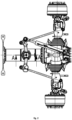
- Presented solution of steering lever 11 assembly according to the invention is in this example embodiment applied on rear axle with single mount tires. As shown in fig. 1 , presented solution is applied on rear steered axle 1 , which is arranged on central backbone tube 2 . Onto the tie-rod 4 and thus respective axle 1 , is acted by hydraulic cylinder 3 through the steering lever 11 .
- Presented solution uses maintenance-free spherical plain bearings 5 , 6 of two sizes. Smaller bearing 5 is pressed onto the upper part of the pin 7 on second cylindrical surface 24 and larger bearing 6 onto the lower part of the pin 7 on first cylindrical surface 25 . Both bearings 5 , 6 are pressed into the steering lever 11 and allow the transfer of radial forces F AR , F BR and axial forces F BA , see fig. 6 . Sliding forces and tilting moments consisting of axial forces F BA and radial forces F AR , F BR on respective arms, are held by the pin 7 inserted into the bearing housing 9 and secured above the bearing housing 9 using a nut 8 . Using cylindrical surface 22 , the pin 7 is propped in the steering box 10 , which makes part of the central backbone tube 2 .
- Fit in the steering box 10 takes part in holding the radial force F AR in the assembly in the first point A .
- Adjusting play in the spherical bearings 5 , 6 is done using lock nut 12 and clamping washer 15 .
- the full installation group, i.e. bearing housing 9 , bearings 5 , 6 and steering lever 11, is fixed in the steering box 10 of the central backbone tube 2 using four bolts 14. Bearings 5 , 6 are protected against the ingress of impurities by a pair of cassette gaskets 13 .
- This arrangement according to the invention will increase bearing capacity and prolong the service life of the steering lever 11 assembly. It will also, thanks to the better sealing and use of maintenance-free mearings 5 , 6 remove or at least considerably reduce maintenance requirements.
Landscapes
- Engineering & Computer Science (AREA)
- General Engineering & Computer Science (AREA)
- Mechanical Engineering (AREA)
- Chemical & Material Sciences (AREA)
- Combustion & Propulsion (AREA)
- Transportation (AREA)
- Physics & Mathematics (AREA)
- Fluid Mechanics (AREA)
- Steering-Linkage Mechanisms And Four-Wheel Steering (AREA)
- Mounting Of Bearings Or Others (AREA)
Abstract
Steering lever (11) assembly, wherein the steering lever (11) is set on a pin (7), which is, through top and bottom plain bearing, arranged respectively at the top and bottom end of the pin (7), fitted in a sealing fashion respectively in bearing housing (9) and in the steering box (10) and secured to the steering box (10) through bearing housing (9) using bolts (14), wherein the pin (7) has a head (22) and a shank (23), where the head (22) has larger diameter than the shank (23), wherein the plain bearings are made as spherical plain bearings (5, 6).
Description
- The invention relates to the steering lever assembly, particularly for one or more steered axles with single mount tires, i.e. axles with only one wheel on each side of the axle, and particularly rear axles with single mount tires. The presented invention particularly relates to the steering lever assembly, where the steering lever is set on a pin, which is through top and bottom plain bearing, arranged respectively at the top and bottom end of the pin, fitted in a sealed fashion respectively in the bearing housing and in the steering box, and attached to the steering box through the bearing housing using bolts, wherein the pin has a head and a shank, where the head has larger diameter than the shank.
- At present, slide fits are most often used for rear steered axles at TATRA chassis, see
figs. 3 and4 . Part of the assembly is a pin (7) pressed into the steering lever (11). The top radial plain bearing consists of the head of the pin together with a radial top ring (16), which is pressed into the bearing housing (9). Bottom radial plain bearing consists of two rings (17, 18). The internal ring (17) is pressed onto the shank of the pin and the external ring (18) is pressed into the steering box on the central backbone tube (10). Axial forces are held by two pans (19), where the top one of them is applied under the head of the pin and the bottom one above the internal ring. Adjustment of axial play is done using ground washers (21), which delimit the space between the top ring and bearing housing. The space of steering lever assembly is sealed using two O-rings (20). Lubricating, respective supplementary lubricating of the assembly is done using a grease nipple in the bearing housing. The lubricating grease is conveyed to friction surfaces using a central bore in the pin. The whole assembly is screwed using four bolts (14) to the steering box. - Disadvantage of this solution is inferior sealing. At the ingress of impurities, e.g. owing to teared or worn out O-ring, impurities get into the sliding surfaces of the bearing, which causes jamming of the whole assembly. Another disadvantage is the high number of parts produced.
- The solution for the construction group in question is also known from the
CZ28777U - Also a steering lever of rear steered axle produced as a class I lever fitted on vertical bearing, is known from
DE3741144 . Formation of this vertical bearing is not described in this document. - Ball pin, especially for the suspension of wheels of a vehicle, having plain bearings, is known from the document
US2018258982 . Steering lever assembly using such pin is not described in this quoted document. - The disadvantages of the above mentioned prior art are solved by a steering lever assembly, where the steering lever is set on a pin, which is through top and bottom plain bearing, arranged respectively at the top and bottom end of the pin, fitted in a sealed fashion respectively in the bearing housing and in the steering box, and attached to the steering box through the bearing housing using bolts, wherein the pin has a head and a shank, where the head has larger diameter than the shank. According to the invention, the plain bearings are manufactured as spherical plain bearings.
- An advantageous embodiment of the assembly according to the invention features the pin being placed with its head in the box and with the end of the shank, provided with and end external thread, in the bearing housing, wherein the end of the shank is secured using a nut behind the bearing housing.
- Another advantageous embodiment of the assembly according to the invention features the shank being equipped with two cylindrical surfaces, out of which the first cylindrical surface is adapted for fitting the bigger spherical bearing and has larger diameter than the second cylindrical surface, which is adapted for fitting the smaller spherical bearing.
- Another advantageous embodiment of the assembly according to the invention features the end of the second cylindrical surface provided with another external thread, which, together with a lock nut arranged on it, and a clamping washer, are adapted for the adjustment of play in the bearings.
- Another advantageous embodiment of the assembly according to the invention features cassette gaskets to prevent the ingress of impurities.
- The advantage of the presented invention is the possibility of increasing the transferred forces using two maintenance-free spherical plain bearings. The presented solution also reduces manufacturing costs among others by reducing the number of parts of the whole assembly. The presented invention also provides higher quality sealing of the steering lever assembly, or the respective bearings' bodies.
- The invention will be explained in more detail using a particular example embodiment shown in the drawings, of which
- fig. 1
- axonometric view of the installation of a steered rear axle with steering lever,
- fig. 2
- view of the installation with the hint of section plane A-A, in plan view,
- fig. 3
- steering lever assembly according to the state of the art,
- fig. 4
- view of the ground washers in detail D from
fig. 3 , - fig. 5
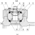
- steering lever assembly according to the invention, and
- fig. 6
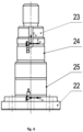
- pin according to the invention with functional surfaces marked and girder marking of bearings' centres.
- Presented solution of
steering lever 11 assembly according to the invention is in this example embodiment applied on rear axle with single mount tires. As shown infig. 1 , presented solution is applied on rear steeredaxle 1, which is arranged oncentral backbone tube 2. Onto the tie-rod 4 and thusrespective axle 1, is acted byhydraulic cylinder 3 through thesteering lever 11. - Presented solution uses maintenance-free spherical
plain bearings Smaller bearing 5 is pressed onto the upper part of thepin 7 on secondcylindrical surface 24 and larger bearing 6 onto the lower part of thepin 7 on firstcylindrical surface 25. Bothbearings steering lever 11 and allow the transfer of radial forces FAR, FBR and axial forces FBA, seefig. 6 . Sliding forces and tilting moments consisting of axial forces FBA and radial forces FAR, FBR on respective arms, are held by thepin 7 inserted into the bearinghousing 9 and secured above the bearinghousing 9 using anut 8. Usingcylindrical surface 22, thepin 7 is propped in thesteering box 10, which makes part of thecentral backbone tube 2. - Fit in the
steering box 10 takes part in holding the radial force FAR in the assembly in the first point A. Adjusting play in thespherical bearings lock nut 12 and clampingwasher 15. The full installation group, i.e. bearinghousing 9,bearings steering lever 11, is fixed in thesteering box 10 of thecentral backbone tube 2 using fourbolts 14.Bearings cassette gaskets 13. - Sliding forces and tilting moments are transferred from the
steering lever 11 ontobearings pin 7. Another radial force FBR in second point B is held by the firstcylindrical surface 24 of theshank 23 and axial force in second point B is transferred by annular area into the bearinghousing 9. - This arrangement according to the invention will increase bearing capacity and prolong the service life of the
steering lever 11 assembly. It will also, thanks to the better sealing and use of maintenance-free mearings - Although the present invention was further described in connection with certain advantageous embodiments, it is not the purpose of this description to limit its scope to such described embodiments only. On the contrary, the aim of this description is to comprise and cover all alternatives, modifications and equivalents of such embodiments, which belong to the subject-matter and claimed scope of the presented invention, as defined in attached claims.
- Both above mentioned and further mentioned features according to the invention could be used individually as stand-alone, or in any mutual combinations, if not otherwise stated or if there is no clear contradiction in the context.
- References stated in dependent claims refer to other embodiments of the subject-matter of the independent claim using the features of the respective dependent claim. But they don't mean resignation on reaching independent, objective protection for the features of these dependent claims.
- The invention thus isn't limited to the embodiment described, and a person skilled in the art can embody the details of the invention using many adaptations within the scope of the attached claims.
-
- 1
- axle
- 2
- central backbone tube
- 3
- hydraulic cylinder
- 4
- tie-rod
- 5
- smaller bearing
- 6
- larger bearing
- 7
- pin
- 8
- nut
- 9
- bearing housing
- 10
- steering box
- 11
- steering lever
- 12
- lock nut
- 13
- cassette gasket
- 14
- bolt
- 15
- clamping washer
- 16
- top ring
- 17
- internal ring
- 18
- external ring
- 19
- pan
- 20
- O-ring
- 21
- ground washer
- 22
- head
- 23
- shank
- 24
- second cylindrical surface
- 25
- first cylindrical surface
- A
- first point
- B
- second point
- FAR
- radial force in point A
- FBA
- axial force
- FBR
- radial force in point B
Claims (5)
- Steering lever (11) assembly, wherein the steering lever (11) is set on a pin (7), which is, through top and bottom plain bearing, arranged respectively at the top and bottom end of the pin (7), fitted in a sealing fashion respectively in bearing housing (9) and in the steering box (10) and secured to the steering box (10) through bearing housing (9) using bolts (14), wherein the pin (7) has a head (22) and a shank (23), where the head (22) has larger diameter than the shank (23), characterised in that the plain bearings are made as spherical plain bearings (5, 6).
- Assembly according to claim 1, characterised in that the pin (7) is placed with its head in the box (10) and the end of the shank (23), provided with an end external thread, in the bearing housing (9), wherein the end of the shank (23) is, behind the bearing housing (9), secured using a nut (8).
- Assembly according to claim 1 or 2, characterised in that the shank (23) is provided with two cylindrical surfaces (24, 25), out of which the first cylindrical surface (25) is adapted for placing the larger spherical bearing (6) and it has larger diameter than the second cylindrical surface (24), which is adapted for placing the smaller spherical bearing (5).
- Assembly according to anyone of claims 1 to 3, characterised in that the end of the second cylindrical surface (24) is provided with another external thread, which is, together with a lock nut (12) and clamping washer (15) arranged on it, adapted for adjusting the play in the bearings (5, 6).
- Assembly according to anyone of claims 1 to 4, characterised in that the bearings (5, 6) have cassette gaskets (13) allocated to prevent the ingress of impurities.
Applications Claiming Priority (1)
| Application Number | Priority Date | Filing Date | Title |
|---|---|---|---|
| CZ2023-440A CZ310204B6 (en) | 2023-11-15 | 2023-11-15 | A mounting for steering lever |
Related Parent Applications (1)
| Application Number | Title | Priority Date | Filing Date |
|---|---|---|---|
| CZ2023440 Previously-Filed-Application | 2023-11-15 |
Publications (1)
| Publication Number | Publication Date |
|---|---|
| EP4556729A1 true EP4556729A1 (en) | 2025-05-21 |
Family
ID=93377633
Family Applications (1)
| Application Number | Title | Priority Date | Filing Date |
|---|---|---|---|
| EP24212420.4A Pending EP4556729A1 (en) | 2023-11-15 | 2024-11-12 | Steering lever assembly |
Country Status (2)
| Country | Link |
|---|---|
| EP (1) | EP4556729A1 (en) |
| CZ (1) | CZ310204B6 (en) |
Citations (7)
| Publication number | Priority date | Publication date | Assignee | Title |
|---|---|---|---|---|
| DE3741144A1 (en) | 1987-12-04 | 1989-06-22 | Bayerische Motoren Werke Ag | Wheel suspension for steerable rear wheels of motor vehicles |
| US6499752B1 (en) * | 2000-08-07 | 2002-12-31 | Dana Corporation | Steer axle assembly |
| FR2842162A1 (en) * | 2002-07-09 | 2004-01-16 | Renault Vehicules Ind | JOINT PIVOT CONNECTING THE ROCKER AND THE HEAD OF A DIRECTION AXIS OF AN INDUSTRIAL VEHICLE |
| CN1496905A (en) * | 2002-06-03 | 2004-05-19 | �����ι�˾ | Non-drive front axle steering knuckle |
| CZ28777U1 (en) | 2015-09-24 | 2015-11-02 | Tatra Trucks A.S. | Mounting of steering system double-arm lever for vehicles with backbone-type chassis and with independent wheel suspension |
| US20180258982A1 (en) | 2017-03-10 | 2018-09-13 | Federal-Mogul Motorparts Corporation | Ball Joint Assembly |
| US20230061119A1 (en) * | 2021-08-27 | 2023-03-02 | Joy Global Underground Mining Llc | Bearing assembly for a wheel unit |
Family Cites Families (2)
| Publication number | Priority date | Publication date | Assignee | Title |
|---|---|---|---|---|
| CS274239B1 (en) * | 1988-12-30 | 1991-04-11 | Ladislav Muller | Thrust hinged self-lubricating bearing with inside packing |
| CN107554289B (en) * | 2017-08-15 | 2023-09-19 | 十堰戎马汽车特种传动有限公司 | Automobile chassis |
-
2023
- 2023-11-15 CZ CZ2023-440A patent/CZ310204B6/en unknown
-
2024
- 2024-11-12 EP EP24212420.4A patent/EP4556729A1/en active Pending
Patent Citations (7)
| Publication number | Priority date | Publication date | Assignee | Title |
|---|---|---|---|---|
| DE3741144A1 (en) | 1987-12-04 | 1989-06-22 | Bayerische Motoren Werke Ag | Wheel suspension for steerable rear wheels of motor vehicles |
| US6499752B1 (en) * | 2000-08-07 | 2002-12-31 | Dana Corporation | Steer axle assembly |
| CN1496905A (en) * | 2002-06-03 | 2004-05-19 | �����ι�˾ | Non-drive front axle steering knuckle |
| FR2842162A1 (en) * | 2002-07-09 | 2004-01-16 | Renault Vehicules Ind | JOINT PIVOT CONNECTING THE ROCKER AND THE HEAD OF A DIRECTION AXIS OF AN INDUSTRIAL VEHICLE |
| CZ28777U1 (en) | 2015-09-24 | 2015-11-02 | Tatra Trucks A.S. | Mounting of steering system double-arm lever for vehicles with backbone-type chassis and with independent wheel suspension |
| US20180258982A1 (en) | 2017-03-10 | 2018-09-13 | Federal-Mogul Motorparts Corporation | Ball Joint Assembly |
| US20230061119A1 (en) * | 2021-08-27 | 2023-03-02 | Joy Global Underground Mining Llc | Bearing assembly for a wheel unit |
Also Published As
| Publication number | Publication date |
|---|---|
| CZ2023440A3 (en) | 2024-11-13 |
| CZ310204B6 (en) | 2024-11-13 |
Similar Documents
| Publication | Publication Date | Title |
|---|---|---|
| US8967371B2 (en) | Stub shaft and bearing assembly and conveyor idler roller incorporating same | |
| KR100486471B1 (en) | Wheel mounting with a bearing race embedded in a cast component | |
| RU2127688C1 (en) | Vehicle hinge joint unit (design versions) and twin taper roller bearing unit | |
| US10415632B2 (en) | Bearing for vehicle suspension | |
| CN1088810C (en) | Bearing assembly | |
| HU226515B1 (en) | Steer axle assembly | |
| US11162529B2 (en) | Double row tapered bearing with press fit preloading elements | |
| US6827359B2 (en) | Non-drive front axle steering knuckle | |
| US6343889B1 (en) | Split-socket ball joint | |
| CN114909393B (en) | Self-pretightening double-row angular contact ball bearing with large caliber | |
| CN218343184U (en) | Bearing support structure of commercial car intermediate axle transfer case | |
| US20050073123A1 (en) | Vehicle corner module and assembly comprising such module | |
| AU2021206225B2 (en) | Retention system for bearing member | |
| CZ2023440A3 (en) | Steering lever storage | |
| DE102005032283B3 (en) | Combined rolling and plain bearings | |
| DE102004009202B4 (en) | wheel bearing unit | |
| DE112006003937B4 (en) | Drive section for use in a bearing arrangement | |
| CN224146017U (en) | An articulated structure for a wheeled container transport machine | |
| CN214928696U (en) | Maintenance-free integral wheel and integral roller device for sintering trolley | |
| DE102023207336A1 (en) | wheel bearing arrangement | |
| US20210277952A1 (en) | Wheel bearing outer ring | |
| CN112238910A (en) | Steering device, steering assembly using steering device and workpiece turnover vehicle | |
| GB1581179A (en) | Disc harrows | |
| GB1581180A (en) | Bearing assembly |
Legal Events
| Date | Code | Title | Description |
|---|---|---|---|
| PUAI | Public reference made under article 153(3) epc to a published international application that has entered the european phase |
Free format text: ORIGINAL CODE: 0009012 |
|
| STAA | Information on the status of an ep patent application or granted ep patent |
Free format text: STATUS: THE APPLICATION HAS BEEN PUBLISHED |
|
| AK | Designated contracting states |
Kind code of ref document: A1 Designated state(s): AL AT BE BG CH CY CZ DE DK EE ES FI FR GB GR HR HU IE IS IT LI LT LU LV MC ME MK MT NL NO PL PT RO RS SE SI SK SM TR |
|
| STAA | Information on the status of an ep patent application or granted ep patent |
Free format text: STATUS: REQUEST FOR EXAMINATION WAS MADE |
|
| 17P | Request for examination filed |
Effective date: 20251118 |