EP4556703A1 - Mechanically switchable electric machines for electrified propulsion - Google Patents
Mechanically switchable electric machines for electrified propulsion Download PDFInfo
- Publication number
- EP4556703A1 EP4556703A1 EP24210204.4A EP24210204A EP4556703A1 EP 4556703 A1 EP4556703 A1 EP 4556703A1 EP 24210204 A EP24210204 A EP 24210204A EP 4556703 A1 EP4556703 A1 EP 4556703A1
- Authority
- EP
- European Patent Office
- Prior art keywords
- electrical machine
- gearbox
- coupling device
- rotational energy
- turbine engine
- Prior art date
- Legal status (The legal status is an assumption and is not a legal conclusion. Google has not performed a legal analysis and makes no representation as to the accuracy of the status listed.)
- Pending
Links
Images

Classifications
-
- F—MECHANICAL ENGINEERING; LIGHTING; HEATING; WEAPONS; BLASTING
- F02—COMBUSTION ENGINES; HOT-GAS OR COMBUSTION-PRODUCT ENGINE PLANTS
- F02C—GAS-TURBINE PLANTS; AIR INTAKES FOR JET-PROPULSION PLANTS; CONTROLLING FUEL SUPPLY IN AIR-BREATHING JET-PROPULSION PLANTS
- F02C7/00—Features, components parts, details or accessories, not provided for in, or of interest apart form groups F02C1/00 - F02C6/00; Air intakes for jet-propulsion plants
- F02C7/32—Arrangement, mounting, or driving, of auxiliaries
-
- H—ELECTRICITY
- H02—GENERATION; CONVERSION OR DISTRIBUTION OF ELECTRIC POWER
- H02K—DYNAMO-ELECTRIC MACHINES
- H02K11/00—Structural association of dynamo-electric machines with electric components or with devices for shielding, monitoring or protection
- H02K11/30—Structural association with control circuits or drive circuits
-
- B—PERFORMING OPERATIONS; TRANSPORTING
- B64—AIRCRAFT; AVIATION; COSMONAUTICS
- B64D—EQUIPMENT FOR FITTING IN OR TO AIRCRAFT; FLIGHT SUITS; PARACHUTES; ARRANGEMENT OR MOUNTING OF POWER PLANTS OR PROPULSION TRANSMISSIONS IN AIRCRAFT
- B64D27/00—Arrangement or mounting of power plants in aircraft; Aircraft characterised by the type or position of power plants
- B64D27/02—Aircraft characterised by the type or position of power plants
- B64D27/30—Aircraft characterised by electric power plants
- B64D27/33—Hybrid electric aircraft
-
- B—PERFORMING OPERATIONS; TRANSPORTING
- B64—AIRCRAFT; AVIATION; COSMONAUTICS
- B64D—EQUIPMENT FOR FITTING IN OR TO AIRCRAFT; FLIGHT SUITS; PARACHUTES; ARRANGEMENT OR MOUNTING OF POWER PLANTS OR PROPULSION TRANSMISSIONS IN AIRCRAFT
- B64D31/00—Power plant control systems; Arrangement of power plant control systems in aircraft
- B64D31/16—Power plant control systems; Arrangement of power plant control systems in aircraft for electric power plants
- B64D31/18—Power plant control systems; Arrangement of power plant control systems in aircraft for electric power plants for hybrid-electric power plants
-
- F—MECHANICAL ENGINEERING; LIGHTING; HEATING; WEAPONS; BLASTING
- F01—MACHINES OR ENGINES IN GENERAL; ENGINE PLANTS IN GENERAL; STEAM ENGINES
- F01D—NON-POSITIVE DISPLACEMENT MACHINES OR ENGINES, e.g. STEAM TURBINES
- F01D15/00—Adaptations of machines or engines for special use; Combinations of engines with devices driven thereby
- F01D15/10—Adaptations for driving, or combinations with, electric generators
-
- F—MECHANICAL ENGINEERING; LIGHTING; HEATING; WEAPONS; BLASTING
- F02—COMBUSTION ENGINES; HOT-GAS OR COMBUSTION-PRODUCT ENGINE PLANTS
- F02C—GAS-TURBINE PLANTS; AIR INTAKES FOR JET-PROPULSION PLANTS; CONTROLLING FUEL SUPPLY IN AIR-BREATHING JET-PROPULSION PLANTS
- F02C7/00—Features, components parts, details or accessories, not provided for in, or of interest apart form groups F02C1/00 - F02C6/00; Air intakes for jet-propulsion plants
- F02C7/36—Power transmission arrangements between the different shafts of the gas turbine plant, or between the gas-turbine plant and the power user
-
- H—ELECTRICITY
- H02—GENERATION; CONVERSION OR DISTRIBUTION OF ELECTRIC POWER
- H02K—DYNAMO-ELECTRIC MACHINES
- H02K7/00—Arrangements for handling mechanical energy structurally associated with dynamo-electric machines, e.g. structural association with mechanical driving motors or auxiliary dynamo-electric machines
- H02K7/10—Structural association with clutches, brakes, gears, pulleys or mechanical starters
- H02K7/116—Structural association with clutches, brakes, gears, pulleys or mechanical starters with gears
-
- H—ELECTRICITY
- H02—GENERATION; CONVERSION OR DISTRIBUTION OF ELECTRIC POWER
- H02K—DYNAMO-ELECTRIC MACHINES
- H02K7/00—Arrangements for handling mechanical energy structurally associated with dynamo-electric machines, e.g. structural association with mechanical driving motors or auxiliary dynamo-electric machines
- H02K7/18—Structural association of electric generators with mechanical driving motors, e.g. with turbines
- H02K7/1807—Rotary generators
- H02K7/1823—Rotary generators structurally associated with turbines or similar engines
-
- F—MECHANICAL ENGINEERING; LIGHTING; HEATING; WEAPONS; BLASTING
- F05—INDEXING SCHEMES RELATING TO ENGINES OR PUMPS IN VARIOUS SUBCLASSES OF CLASSES F01-F04
- F05D—INDEXING SCHEME FOR ASPECTS RELATING TO NON-POSITIVE-DISPLACEMENT MACHINES OR ENGINES, GAS-TURBINES OR JET-PROPULSION PLANTS
- F05D2220/00—Application
- F05D2220/70—Application in combination with
- F05D2220/76—Application in combination with an electrical generator
-
- F—MECHANICAL ENGINEERING; LIGHTING; HEATING; WEAPONS; BLASTING
- F05—INDEXING SCHEMES RELATING TO ENGINES OR PUMPS IN VARIOUS SUBCLASSES OF CLASSES F01-F04
- F05D—INDEXING SCHEME FOR ASPECTS RELATING TO NON-POSITIVE-DISPLACEMENT MACHINES OR ENGINES, GAS-TURBINES OR JET-PROPULSION PLANTS
- F05D2260/00—Function
- F05D2260/40—Transmission of power
- F05D2260/402—Transmission of power through friction drives
- F05D2260/4023—Transmission of power through friction drives through a friction clutch
-
- F—MECHANICAL ENGINEERING; LIGHTING; HEATING; WEAPONS; BLASTING
- F05—INDEXING SCHEMES RELATING TO ENGINES OR PUMPS IN VARIOUS SUBCLASSES OF CLASSES F01-F04
- F05D—INDEXING SCHEME FOR ASPECTS RELATING TO NON-POSITIVE-DISPLACEMENT MACHINES OR ENGINES, GAS-TURBINES OR JET-PROPULSION PLANTS
- F05D2260/00—Function
- F05D2260/40—Transmission of power
- F05D2260/403—Transmission of power through the shape of the drive components
- F05D2260/4031—Transmission of power through the shape of the drive components as in toothed gearing
Definitions
- Example embodiments of the present disclosure pertain to the art of aircraft electrical systems and, in particular, to aircraft electrical architectures that implement a single generator that can be driven by multiple engine spools.
- Modern aircraft engines used in aerospace today typically have multiple shafts that rotate to provide thrust to propel an aircraft. Each of these shafts run at different speeds and are typically decoupled, meaning the shafts are not mechanically linked. Each of these shafts can have a motor/generator coupled to them. These shafts can also interface with a mechanical gearbox to support different speeds or multiple electric machines.
- a single electric machine e.g., a generator, a motor
- Embodiments of the present disclosure which enable the sharing include one or more coupling mechanisms that are configured to couple/decouple the machine to either shaft when commanded through a system or engine controller.
- Example embodiments of the present disclosure are directed to a system including: a first electrical machine; a motor controller device coupled to the first electrical machine, wherein the motor controller device is configured to convert first power generated by the first electrical machine or provide second power to the first electrical machine; and a set of coupling devices configured to mechanically couple or decouple the first electrical machine and a turbine engine based on a mode of the system, wherein the set of coupling devices includes: a first gearbox coupled to the first electrical machine; a first coupling device between the first gearbox and the turbine engine; a second gearbox; a second coupling device between the second gearbox and the turbine engine; and a third coupling device between the first gearbox and the second gearbox.
- the first gearbox is configured to transfer first rotational energy between at least two of the turbine engine, the first electrical machine, or a second electrical machine
- the second gearbox is configured to transfer second rotational energy between at least two of the turbine engine, the first electrical machine, or the second electrical machine
- the third coupling device is configured to transfer third rotational energy between the first gearbox and the second gearbox; or a combination thereof.
- the first coupling device, the second coupling device, and the third coupling device are each in an decoupling state; the first rotational energy is not transferred between any of the turbine engine, the first electrical machine, and the second electrical machine; the second rotational energy is not transferred between any of the turbine engine, the first electrical machine, and the second electrical machine; and the third rotational energy is not transferred between the first gearbox and the second gearbox.
- the first coupling device is in a coupling state and is configured to transfer the first rotational energy between the turbine engine and the first electrical machine;
- the second coupling device is in a decoupling state, and the second rotational energy is not transferred between any of the turbine engine, the first electrical machine, and the second electrical machine;
- the third coupling device is in the decoupling state, and the third rotational energy is not transferred between the first gearbox and the second gearbox.
- the first coupling device is in a coupling state and is configured to transfer the first rotational energy between the turbine engine and the first electrical machine
- the second coupling device is in the coupling state and is configured to transfer the second rotational energy between the turbine engine and the second electrical machine
- the third coupling device is in an decoupling state, and the third rotational energy is not transferred between the first gearbox and the second gearbox.
- the first coupling device is in an decoupling state, and the first rotational energy is not transferred between the turbine engine and the first electrical machine;
- the second coupling device is in the decoupling state, and the second rotational energy is not transferred between the turbine engine and the second electrical machine;
- the third coupling device is in a coupling state and is configured to transfer the third rotational energy between the first gearbox and the second gearbox.
- the first coupling device is in a coupling state and is configured to transfer the first rotational energy between at least two of the turbine engine, the first electrical machine, or the second electrical machine;
- the second coupling device is in an decoupling state, and the second rotational energy is not transferred between the turbine engine and the second electrical machine;
- the third coupling device is in the coupling state and is configured to transfer the third rotational energy between the first gearbox and the second gearbox.
- the first coupling device is in a coupling state and is configured to transfer the first rotational energy between at least two of the turbine engine, the first electrical machine, or the second electrical machine;
- the second coupling device is in the coupling state and is configured to transfer the second rotational energy between at least two of the turbine engine, the first electrical machine, or the second electrical machine;
- the third coupling device is in the coupling state and is configured to transfer the third rotational energy between the first gearbox and the second gearbox.
- the first electrical machine includes a low pressure machine
- the second electrical machine includes a high pressure machine
- the first electrical machine and the second electrical machine each include a low pressure machine.
- the first electrical machine and the second electrical machine each include a high pressure machine.
- the system further includes a control device configured to, based on the mode of the system, control the set of coupling devices in association with at least one of: mechanically coupling or decoupling the first gearbox and the turbine engine; mechanically coupling or decoupling the second gearbox and the turbine engine; and mechanically coupling or decoupling the first gearbox and the second gearbox.
- a control device configured to, based on the mode of the system, control the set of coupling devices in association with at least one of: mechanically coupling or decoupling the first gearbox and the turbine engine; mechanically coupling or decoupling the second gearbox and the turbine engine; and mechanically coupling or decoupling the first gearbox and the second gearbox.
- the first coupling device is mechanically coupled to a first spool of the turbine engine; the second coupling device is mechanically coupled to a second spool of the turbine engine; and the first spool and the second spool are independent of one another.
- Example embodiments of the present disclosure are directed to an apparatus including: a set of coupling devices configured to mechanically couple or decouple a first electrical machine and a turbine engine based on a mode associated with the apparatus, wherein the set of coupling devices includes: a first gearbox coupled to the first electrical machine; a first coupling device between the first gearbox and the turbine engine; a second gearbox coupled; a second coupling device between the second gearbox and the turbine engine; and a third coupling device between the first gearbox and the second gearbox.
- the first gearbox is configured to transfer first rotational energy between at least two of the turbine engine, the first electrical machine, or a second electrical machine
- the second gearbox is configured to transfer second rotational energy between at least two of the turbine engine, the first electrical machine, or the second electrical machine
- the third coupling device is configured to transfer third rotational energy between the first gearbox and the second gearbox, or a combination thereof.
- the first coupling device is in a coupling state and is configured to transfer the first rotational energy between the turbine engine and the first electrical machine;
- the second coupling device is in a decoupling state, and the second rotational energy is not transferred between any of the turbine engine, the first electrical machine, and the second electrical machine;
- the third coupling device is in the decoupling state, and the third rotational energy is not transferred between the first gearbox and the second gearbox.
- the first coupling device is in a coupling state and is configured to transfer the first rotational energy between the turbine engine and the first electrical machine;
- the second coupling device is in the coupling state and is configured to transfer the second rotational energy between the turbine engine and the second electrical machine;
- the third coupling device is in an decoupling state, and the third rotational energy is not transferred between the first gearbox and the second gearbox.
- the first coupling device is in an decoupling state, and the first rotational energy is not transferred between the turbine engine and the first electrical machine;
- the second coupling device is in the decoupling state, and the second rotational energy is not transferred between the turbine engine and the second electrical machine;
- the third coupling device is in a coupling state and is configured to transfer the third rotational energy between the first gearbox and the second gearbox.
- the first coupling device is in a coupling state and is configured to transfer the first rotational energy between at least two of the turbine engine, the first electrical machine, or the second electrical machine;
- the second coupling device is in an decoupling state, and the second rotational energy is not transferred between the turbine engine and the second electrical machine;
- the third coupling device is in the coupling state and is configured to transfer the third rotational energy between the first gearbox and the second gearbox.
- FIG. 1 schematically illustrates a gas turbine engine 20.
- the gas turbine engine 20 is disclosed herein as a two-spool turbofan that generally incorporates a fan section 22, a compressor section 24, a combustor section 26 and a turbine section 28.
- Alternative engines might include other systems or features.
- the fan section 22 drives air along a bypass flow path B in a bypass duct, while the compressor section 24 drives air along a core flow path C for compression and communication into the combustor section 26 then expansion through the turbine section 28.
- FIG. 1 schematically illustrates a gas turbine engine 20.
- the gas turbine engine 20 is disclosed herein as a two-spool turbofan that generally incorporates a fan section 22, a compressor section 24, a combustor section 26 and a turbine section 28.
- Alternative engines might include other systems or features.
- the fan section 22 drives air along a bypass flow path B in a bypass duct
- the compressor section 24 drives air along a core flow path C for compression and communication into the combustor section 26
- the low speed spool 30 generally includes an inner shaft 40 that interconnects a fan 42, a low pressure compressor 44 and a low pressure turbine 46.
- the inner shaft 40 is connected to the fan 42 through a speed change mechanism, which in example gas turbine engine 20 is illustrated as a geared architecture 48 to drive the fan 42 at a lower speed than the low speed spool 30.
- the system 200 includes two electrical machines, a high pressure machine 202 and a low pressure machine 204.
- the system 200 includes the gas turbine 20 of FIG. 1
- the system 200 may include one of the high pressure machine 202 and the low pressure machine 204 and omit the other of the high pressure machine 202 and the low pressure machine 204.
- the system 200 may include two electrical machines on the low pressure spool and one electrical machine (or two electrical machines) on the high pressure spool, in which the high pressure spool machine is selectively couplable (e.g., by associated mechanical and/or electrical components) to either the low pressure spool or the high pressure spool.
- the system 200 may support a configuration in which three electrical machines are coupled to the low pressure spool (e.g., by selective coupling of an electrical machine to the low pressure spool along with two other electrical machines already coupled to the low pressure spool).
- aspects of the system 200 support sharing a single electric machine (e.g., high pressure machine 202, low pressure machine 204) between two independent engine spools. Descriptions herein with respect to a generator may similarly be applied to a motor.
- embodiments of the present disclosure support implementations in which the high pressure machine 202 and the low pressure machine 204 may each be a motor or a generator.
- embodiments of the present disclosure support implementations in which the high pressure machine 202 and/or the low pressure machine 204 are a machine capable of operating in a motor configuration and a generator configuration.
- the system further includes a motor control unit (MCU) 210 (also referred to herein as a first MCU 210 or first motor controller device)).
- the MCU 210 can be configured such that the MCU 210 can control the low pressure machine 204.
- the MCU 210 can optionally be bidirectional.
- the MCU 210 can include an inverter 220 that receives and converts DC power to AC power and provides the AC power to the low pressure machine 204, which may cause the low pressure machine 204 to operate in a motor configuration and provide energy to the gas turbine 20 of FIG. 1 .
- the inverter 220 can be an active inverter and can be controlled to produce a desired output by either an internal controller or by an external controller such as, for example, generator control unit (GCU 240) (also referred to herein as a control device, a generator control device, or a generator controller) shown in FIG. 2 .
- GCU 240 generator control unit
- the MCU 210 can also be configured such that the MCU 210 converts AC power received from the low pressure machine 206 to a DC voltage and outputs the DC voltage.
- the MCU 210 can include a rectifier 222 that receives AC power from the low pressure machine 206 and converts the AC power to DC power.
- the rectifier 222 can be an active rectifier (e.g., provide rectification using actively controlled switches) and can be controlled to produce a desired output by either an internal controller or by an external controller such as GCU 240 shown in FIG. 2 .
- the system 200 can also include a motor control unit 212 (also referred to herein as a second MCU 212 or second motor controller device)).
- the MCU 212 can be configured such that the MCU 212 can control the high pressure machine 202.
- the MCU 212 can optionally be bidirectional.
- the MCU 212 can include an inverter 230 that receives and converts DC power to AC power and provides the AC power to the high pressure machine 202, which may cause the high pressure machine 206 to operate in a motor configuration and provide energy to the gas turbine 20 of FIG. 1 .
- the inverter 220 can be an active inverter and can be controlled to produce a desired output by either an internal controller or by an external controller such as, for example, GCU 240 shown in FIG. 2 .
- the MCU 212 can also be configured such that the MCU 212 converts AC power received from the high pressure machine 202 to a DC voltage and outputs the DC voltage.
- the MCU 212 can include a rectifier 232 that receives AC power from the low pressure machine 206 and converts the AC power to DC power.
- the rectifier 232 can be an active rectifier (e.g., provide rectification using actively controlled switches) and can be controlled to produce a desired output by either an internal controller or by an external controller such as, for example, GCU 240 shown in FIG. 2 .
- the gas turbine engine 20 of FIG. 1 can include a high pressure output shaft 250 and a low pressure output shaft 252 that are respectively connected to high pressure gear box 254 and low pressure gear box 256.
- the high pressure output shaft 250 and low pressure output shaft 252 are respective examples of an outer shaft 50 and an inner shaft 40 described with reference to FIG. 1 , and repeated descriptions of like elements are omitted for brevity.
- the high pressure gear box 254 and low pressure gear box 256 allow rotational energy to be passed from the turbine 20 (e.g., shaft 250, shaft 252) to the high pressure machine 202 and low pressure machine 204 and vice versa.
- a connector 260 (also referred to herein as a coupler/decoupler) is provided.
- the connector 260 includes a connector coupler/decoupler 262 arranged thereon.
- the connector coupler/decoupler 262 can be arranged such that torque provided at one end of the connector 260 is either transmitted to the other end (coupled) or not (decoupled).
- Examples of the connector coupler/decoupler 262 include torque converters, clutches, and the like.
- Other coupler/decouplers described herein e.g., connector coupler/decoupler 264, connector 260
- the high pressure output shaft 250 and the low pressure output shaft 252 respectively include the high pressure output shaft coupler/decoupler 262 and the low pressure output shaft coupler/decoupler 264.
- a coupler/decoupler that is transferring energy/power/torque can be in a "1" state (also referred to herein as a coupling state) and a coupler that is not transferring energy/power/torque can be in a "0" state (also referred to herein as a decoupling state).
- the system modes may correspond to the configurations of the three coupler/decouplers 260, 262, 264.
- (x, y, z) refers to the state of the coupler/decouplers 260, 262, 264, respectively.
- the coupler/decouplers 260, 262, 264 may collectively be referred to as a set of coupling devices or a set of coupling/decoupling devices.
- Embodiments of the present disclosure support generating electricity based on rotational energy and/or providing rotational energy based on a given system mode described herein.
- the turbine 20 is operably connected to the low pressure machine 204 only.
- the turbine 20 is disconnected from the high pressure machine 202, and the gear box 256 and gear box 254 are disconnected from each other.
- the low pressure machine 204 can motor the turbine 20 or receive rotational energy from the turbine 20 and generate electricity.
- the turbine 20 is operably connected to the high pressure machine 202 only.
- the turbine 20 is disconnected from the low pressure machine 204, and the gear box 256 and gear box 254 are disconnected from each other.
- the high pressure machine 202 can motor the turbine 20 or receive rotational energy from the turbine 20 and generate electricity.
- the turbine 20 is operably connected to both the high pressure machine 202 and the low pressure machine 204.
- Both the high pressure machine 202 and the low pressure machine 204 can motor the turbine 20 or receive rotational energy from the turbine 20 and generate electricity. Combinations of both are envisioned. Embodiments of the present disclosure support combinations using the high pressure machine 202 and the low pressure machine 204.
- both the high pressure machine 202 and the low pressure machine 204 may simultaneously or alternately motor the turbine 20.
- both the high pressure machine 202 and the low pressure machine 204 may simultaneously or alternately receive rotational energy from the turbine 20 and generate electricity.
- the system 200 may include an additional transmission element (e.g., a differential or planetary gear set) (not illustrated) to support or compensate for the different rotational speeds of the spools.
- a fifth mode (1,0,0)
- the turbine 20 in not connected to either the high pressure machine 202 or the low pressure machine 204, and the high pressure machine 202 and the low pressure machine 204 are connected to one another.
- the low pressure machine 204 may drive the high pressure machine 202 and the high pressure machine 202 may generate electricity if needed.
- a sixth mode (1,0,1)
- the turbine 20 in connected to the low pressure machine 204, and the high pressure machine 202 and the low pressure machine 204 are connected to one another.
- the high pressure machine 202 may drive/be driven by the low pressure output shaft 252.
- a single drive shaft e.g., low pressure output shaft 252
- the sixth mode can allow for the high pressure machine 202 to be connected to the low pressure gear box 256.
- a seventh mode (1,1,0)
- the turbine 20 in connected to the high pressure machine 202, and the high pressure machine 202 and the low pressure machine 204 are connected to one another.
- the low pressure machine 204 may drive/be driven by the low pressure output shaft 252.
- a single drive shaft e.g., high pressure output shaft 250
- the seventh mode can allow for the low pressure machine 204 to be connected to the high pressure gear box 254.
- the turbine 20 is connected to high pressure machine 202 and the low pressure machine 204, and the high pressure machine 202 and the low pressure machine 204 are connected to one another. Both the high pressure machine 202 and the low pressure machine 204 can motor the turbine 20 or receive rotational energy from the turbine 20 and generate electricity.
- the high pressure machine 202 may drive/be driven by the low pressure output shaft 252 and/or the high pressure output shaft 250.
- the low pressure machine 204 may drive/be driven by the low pressure output shaft 252 and/or the high pressure output shaft 250.
- the system 200 may include an additional transmission element (e.g., a differential or planetary gear set) (not illustrated) to support or compensate for the different rotational speeds of the low pressure output shaft 252 and the high pressure output shaft 250.
- an additional transmission element e.g., a differential or planetary gear set
- the system 200 may omit one or the other of the high pressure machine 202 and the low pressure machine 204, and by having the connector 260 with the connector coupler/decoupler 262 and the connector coupler/decoupler 264, the system 200 can run on either gearbox/spool described herein or the turbine 20, for example, in the sixth and seventh modes.
- Embodiments of the present disclosure are not limited to the high pressure machine 202 and the low pressure machine 204.
- the system 200 may include two high pressure machines 202 (capable of operating according to the same or different high speeds), two MCUs 212, and two high pressure gear boxes 254 which may be operated based on the modes described herein.
- the system 200 may include two low pressure machines 204 (capable of operating according to the same or different low speeds), two MCUs 210, and two low pressure gear boxes 256 which may be operated based on the modes described herein.
- the system 200 may implement the high pressure gear box 254, low pressure gear box 256, connector 260, decoupler 262, and decoupler 264 as a single gearbox having a standalone enclosure, which may provide reduced complexity with respect to system design and total quantity of components.
- the system 200 includes a first electrical machine (e.g., low pressure machine 204).
- the system 200 includes a motor controller device (e.g., MCU 210) coupled to the first electrical machine, wherein the motor controller device is configured to convert first power generated by the first electrical machine or provide second power to the first electrical machine.
- the system 200 includes a set of coupling devices configured to mechanically couple or decouple the first electrical machine and the gas turbine engine 20 based on a mode of the system 200.
- the set of coupling devices may include: a first gearbox (e.g., low pressure gear box 256) coupled to the first electrical machine; a first coupling device (e.g., coupler/decoupler 264) between the first gearbox and the turbine engine; a second gearbox (e.g., high pressure gear box 254); a second coupling device (e.g., coupler/decoupler 262) between the second gearbox and the turbine engine; and a third coupling device (e.g., connector 260) between the first gearbox and the second gearbox.
- a first gearbox e.g., low pressure gear box 256
- a first coupling device e.g., coupler/decoupler 264
- a second gearbox e.g., high pressure gear box 254
- a second coupling device e.g., coupler/decoupler 262
- a third coupling device e.g., connector 260
- the first gearbox is configured to transfer first rotational energy between at least two of the gas turbine engine 20, the first electrical machine, or a second electrical machine (e.g., high pressure machine 202); the second gearbox is configured to transfer second rotational energy between at least two of the gas turbine engine 20, the first electrical machine, or the second electrical machine; the third coupling device is configured to transfer third rotational energy between the first gearbox and the second gearbox; or a combination thereof.
- a second electrical machine e.g., high pressure machine 202
- the second gearbox is configured to transfer second rotational energy between at least two of the gas turbine engine 20, the first electrical machine, or the second electrical machine
- the third coupling device is configured to transfer third rotational energy between the first gearbox and the second gearbox; or a combination thereof.
- Gearboxes on aircraft engines today only use the high spool as a means of generating.
- the low spool of the engine may be used to also turn a generator or be driven by a motor.
- the high spool can also be motored.
- a dedicated electric machine would be used on both spools, but embodiments can allow a single machine to be shared for both spools, reducing the weight of the system.
Landscapes
- Engineering & Computer Science (AREA)
- Chemical & Material Sciences (AREA)
- Combustion & Propulsion (AREA)
- Power Engineering (AREA)
- Mechanical Engineering (AREA)
- General Engineering & Computer Science (AREA)
- Aviation & Aerospace Engineering (AREA)
- Connection Of Motors, Electrical Generators, Mechanical Devices, And The Like (AREA)
Abstract
A system includes: a first electrical machine (202, 204); a motor controller device (210) coupled to the first electrical machine (202, 204), wherein the motor controller device (210) is configured to convert first power generated by the first electrical machine (202, 204) or provide second power to the first electrical machine (202, 204); and a set of coupling devices configured to mechanically couple or decouple the first electrical machine (202, 204) and a turbine engine based on a mode of the system. The set of coupling devices includes: a first gearbox coupled to the first electrical machine (202, 204); a first coupling device between the first gearbox and the turbine engine; a second gearbox; a second coupling device between the second gearbox and the turbine engine; and a third coupling device between the first gearbox and the second gearbox.
Description
- This application claims the benefit of
U.S. Provisional Application No. 63/599,072 filed November 15, 2023 - Example embodiments of the present disclosure pertain to the art of aircraft electrical systems and, in particular, to aircraft electrical architectures that implement a single generator that can be driven by multiple engine spools.
- Modern aircraft engines used in aerospace today typically have multiple shafts that rotate to provide thrust to propel an aircraft. Each of these shafts run at different speeds and are typically decoupled, meaning the shafts are not mechanically linked. Each of these shafts can have a motor/generator coupled to them. These shafts can also interface with a mechanical gearbox to support different speeds or multiple electric machines.
- Disclosed is a system in which a single electric machine (e.g., a generator, a motor) can be shared between the two independent engine spools. Embodiments of the present disclosure which enable the sharing include one or more coupling mechanisms that are configured to couple/decouple the machine to either shaft when commanded through a system or engine controller.
- Example embodiments of the present disclosure are directed to a system including: a first electrical machine; a motor controller device coupled to the first electrical machine, wherein the motor controller device is configured to convert first power generated by the first electrical machine or provide second power to the first electrical machine; and a set of coupling devices configured to mechanically couple or decouple the first electrical machine and a turbine engine based on a mode of the system, wherein the set of coupling devices includes: a first gearbox coupled to the first electrical machine; a first coupling device between the first gearbox and the turbine engine; a second gearbox; a second coupling device between the second gearbox and the turbine engine; and a third coupling device between the first gearbox and the second gearbox.
- In any one or combination of the embodiments disclosed herein, based on the mode of the system: the first gearbox is configured to transfer first rotational energy between at least two of the turbine engine, the first electrical machine, or a second electrical machine; the second gearbox is configured to transfer second rotational energy between at least two of the turbine engine, the first electrical machine, or the second electrical machine; the third coupling device is configured to transfer third rotational energy between the first gearbox and the second gearbox; or a combination thereof.
- In any one or combination of the embodiments disclosed herein, based on the mode of the system: the first coupling device, the second coupling device, and the third coupling device are each in an decoupling state; the first rotational energy is not transferred between any of the turbine engine, the first electrical machine, and the second electrical machine; the second rotational energy is not transferred between any of the turbine engine, the first electrical machine, and the second electrical machine; and the third rotational energy is not transferred between the first gearbox and the second gearbox.
- In any one or combination of the embodiments disclosed herein, based on the mode of the system: the first coupling device is in a coupling state and is configured to transfer the first rotational energy between the turbine engine and the first electrical machine; the second coupling device is in a decoupling state, and the second rotational energy is not transferred between any of the turbine engine, the first electrical machine, and the second electrical machine; and the third coupling device is in the decoupling state, and the third rotational energy is not transferred between the first gearbox and the second gearbox.
- In any one or combination of the embodiments disclosed herein, based on the mode of the system: the first coupling device is in a coupling state and is configured to transfer the first rotational energy between the turbine engine and the first electrical machine; the second coupling device is in the coupling state and is configured to transfer the second rotational energy between the turbine engine and the second electrical machine; and the third coupling device is in an decoupling state, and the third rotational energy is not transferred between the first gearbox and the second gearbox.
- In any one or combination of the embodiments disclosed herein, based on the mode of the system: the first coupling device is in an decoupling state, and the first rotational energy is not transferred between the turbine engine and the first electrical machine; the second coupling device is in the decoupling state, and the second rotational energy is not transferred between the turbine engine and the second electrical machine; and the third coupling device is in a coupling state and is configured to transfer the third rotational energy between the first gearbox and the second gearbox.
- In any one or combination of the embodiments disclosed herein, based on the mode of the system: the first coupling device is in a coupling state and is configured to transfer the first rotational energy between at least two of the turbine engine, the first electrical machine, or the second electrical machine; the second coupling device is in an decoupling state, and the second rotational energy is not transferred between the turbine engine and the second electrical machine; and the third coupling device is in the coupling state and is configured to transfer the third rotational energy between the first gearbox and the second gearbox.
- In any one or combination of the embodiments disclosed herein, based on the mode of the system: the first coupling device is in a coupling state and is configured to transfer the first rotational energy between at least two of the turbine engine, the first electrical machine, or the second electrical machine; the second coupling device is in the coupling state and is configured to transfer the second rotational energy between at least two of the turbine engine, the first electrical machine, or the second electrical machine; and the third coupling device is in the coupling state and is configured to transfer the third rotational energy between the first gearbox and the second gearbox.
- In any one or combination of the embodiments disclosed herein: the first electrical machine includes a low pressure machine; and the second electrical machine includes a high pressure machine.
- In any one or combination of the embodiments disclosed herein: the first electrical machine and the second electrical machine each include a low pressure machine.
- In any one or combination of the embodiments disclosed herein: the first electrical machine and the second electrical machine each include a high pressure machine.
- In any one or combination of the embodiments disclosed herein, the system further includes a control device configured to, based on the mode of the system, control the set of coupling devices in association with at least one of: mechanically coupling or decoupling the first gearbox and the turbine engine; mechanically coupling or decoupling the second gearbox and the turbine engine; and mechanically coupling or decoupling the first gearbox and the second gearbox.
- In any one or combination of the embodiments disclosed herein: the first coupling device is mechanically coupled to a first spool of the turbine engine; the second coupling device is mechanically coupled to a second spool of the turbine engine; and the first spool and the second spool are independent of one another.
- Example embodiments of the present disclosure are directed to an apparatus including: a set of coupling devices configured to mechanically couple or decouple a first electrical machine and a turbine engine based on a mode associated with the apparatus, wherein the set of coupling devices includes: a first gearbox coupled to the first electrical machine; a first coupling device between the first gearbox and the turbine engine; a second gearbox coupled; a second coupling device between the second gearbox and the turbine engine; and a third coupling device between the first gearbox and the second gearbox.
- In any one or combination of the embodiments disclosed herein, based on the mode associated with the apparatus: the first gearbox is configured to transfer first rotational energy between at least two of the turbine engine, the first electrical machine, or a second electrical machine; the second gearbox is configured to transfer second rotational energy between at least two of the turbine engine, the first electrical machine, or the second electrical machine; the third coupling device is configured to transfer third rotational energy between the first gearbox and the second gearbox, or a combination thereof.
- In any one or combination of the embodiments disclosed herein, based on the mode associated with the apparatus: the first coupling device is in a coupling state and is configured to transfer the first rotational energy between the turbine engine and the first electrical machine; the second coupling device is in a decoupling state, and the second rotational energy is not transferred between any of the turbine engine, the first electrical machine, and the second electrical machine; and the third coupling device is in the decoupling state, and the third rotational energy is not transferred between the first gearbox and the second gearbox.
- In any one or combination of the embodiments disclosed herein, based on the mode associated with the apparatus: the first coupling device is in a coupling state and is configured to transfer the first rotational energy between the turbine engine and the first electrical machine; the second coupling device is in the coupling state and is configured to transfer the second rotational energy between the turbine engine and the second electrical machine; and the third coupling device is in an decoupling state, and the third rotational energy is not transferred between the first gearbox and the second gearbox.
- In any one or combination of the embodiments disclosed herein, based on the mode associated with the apparatus: the first coupling device is in an decoupling state, and the first rotational energy is not transferred between the turbine engine and the first electrical machine; the second coupling device is in the decoupling state, and the second rotational energy is not transferred between the turbine engine and the second electrical machine; and the third coupling device is in a coupling state and is configured to transfer the third rotational energy between the first gearbox and the second gearbox.
- In any one or combination of the embodiments disclosed herein, based on the mode associated with the apparatus: the first coupling device is in a coupling state and is configured to transfer the first rotational energy between at least two of the turbine engine, the first electrical machine, or the second electrical machine; the second coupling device is in an decoupling state, and the second rotational energy is not transferred between the turbine engine and the second electrical machine; and the third coupling device is in the coupling state and is configured to transfer the third rotational energy between the first gearbox and the second gearbox.
- In any one or combination of the embodiments disclosed herein, based on the mode associated with the apparatus: the first coupling device is in a coupling state and is configured to transfer the first rotational energy between at least two of the turbine engine, the first electrical machine, or the second electrical machine; the second coupling device is in the coupling state and is configured to transfer the second rotational energy between at least two of the turbine engine, the first electrical machine, or the second electrical machine; and the third coupling device is in the coupling state and is configured to transfer the third rotational energy between the first gearbox and the second gearbox.
- Additional features and advantages are realized through the techniques of the present disclosure. Other embodiments and aspects of the disclosure are described in detail herein and are considered a part of the claimed technical concept. For a better understanding of the disclosure with the advantages and the features, refer to the description and to the drawings.
- The following descriptions should not be considered limiting in any way. With reference to the accompanying drawings, like elements are numbered alike:
-
FIG. 1 is a partial cross-sectional view of a gas turbine engine; and -
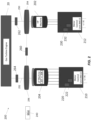
FIG. 2 is a block diagram showing a system according to one embodiment. The system can include only one of the electric machines in one embodiment. - A detailed description of one or more embodiments of the disclosed apparatus and method are presented herein by way of example and not limitation with reference to the Figures. While the current application is directed to driving generators or motors,
FIG. 1 is provided for context. -
FIG. 1 schematically illustrates agas turbine engine 20. Thegas turbine engine 20 is disclosed herein as a two-spool turbofan that generally incorporates afan section 22, acompressor section 24, acombustor section 26 and aturbine section 28. Alternative engines might include other systems or features. Thefan section 22 drives air along a bypass flow path B in a bypass duct, while thecompressor section 24 drives air along a core flow path C for compression and communication into thecombustor section 26 then expansion through theturbine section 28. Although depicted as a two-spool turbofan gas turbine engine in the disclosed non-limiting embodiment, it should be understood that the concepts described herein are not limited to use with two-spool turbofans as the teachings may be applied to other types of turbine engines including three-spool architectures. - The
example engine 20 generally includes alow speed spool 30 and ahigh speed spool 32 mounted for rotation about an engine central longitudinal axis A relative to an enginestatic structure 36 viaseveral bearing systems 38. It should be understood thatvarious bearing systems 38 at various locations may alternatively or additionally be provided, and the location ofbearing systems 38 may be varied as appropriate to the application. - The
low speed spool 30 generally includes aninner shaft 40 that interconnects afan 42, alow pressure compressor 44 and alow pressure turbine 46. Theinner shaft 40 is connected to thefan 42 through a speed change mechanism, which in examplegas turbine engine 20 is illustrated as a gearedarchitecture 48 to drive thefan 42 at a lower speed than thelow speed spool 30. - The
high speed spool 32 includes anouter shaft 50 that interconnects ahigh pressure compressor 52 andhigh pressure turbine 54. Acombustor 56 is arranged inexample gas turbine 20 between thehigh pressure compressor 52 and thehigh pressure turbine 54. An enginestatic structure 36 is arranged generally between thehigh pressure turbine 54 and thelow pressure turbine 46. The enginestatic structure 36 further supports bearingsystems 38 in theturbine section 28. Theinner shaft 40 and theouter shaft 50 are concentric and rotate viabearing systems 38 about the engine central longitudinal axis A which is collinear with their longitudinal axes. - The core airflow is compressed by the
low pressure compressor 44 then thehigh pressure compressor 52, mixed and burned with fuel in thecombustor 56, then expanded over thehigh pressure turbine 54 andlow pressure turbine 46. Theturbines low speed spool 30 andhigh speed spool 32 in response to the expansion. It will be appreciated that each of the positions of thefan section 22,compressor section 24,combustor section 26,turbine section 28, and fandrive gear system 48 may be varied. For example,gear system 48 may be located aft ofcombustor section 26 or even aft ofturbine section 28, andfan section 22 may be positioned forward or aft of the location ofgear system 48. - One or more electrical machines (e.g., generators/motors) can be attached to both the low speed spool and the high speed spool. Herein, an electrical machine connected to the low speed spool shall be referred to as a low pressure machine and an electrical machine connected to the high speed spool shall be referred to as a high pressure machine. The skilled artisan will understand that the connection can be may, for example, by rotor blades on the low speed spool and that similar connections can be made on the high speed spool.
- With reference now to
FIG. 2 , anexample system 200 in accordance with one or more embodiments of the present disclosure is shown. As illustrated, thesystem 200 includes two electrical machines, ahigh pressure machine 202 and alow pressure machine 204. Thesystem 200 includes thegas turbine 20 ofFIG. 1 In some embodiments, thesystem 200 may include one of thehigh pressure machine 202 and thelow pressure machine 204 and omit the other of thehigh pressure machine 202 and thelow pressure machine 204. - Embodiments of the
system 200 are not limited to one electrical machine (e.g., onehigh pressure machine 202, one low pressure machine 204) on each spool. For example, in some embodiments, thesystem 200 may include two electrical machines on the high pressure spool and one electrical machine (or two electrical machines) on the low pressure spool, in which the low pressure spool machine is selectively couplable (e.g., by associated mechanical and/or electrical components) to either the low pressure spool or the high pressure spool. In this example, thesystem 200 may support a configuration in which three electrical machines are coupled to the low pressure spool (e.g., by selective coupling of an electrical machine to the high pressure spool along with two other electrical machines already coupled to the high pressure spool). - In some embodiments, the
system 200 may include two electrical machines on the low pressure spool and one electrical machine (or two electrical machines) on the high pressure spool, in which the high pressure spool machine is selectively couplable (e.g., by associated mechanical and/or electrical components) to either the low pressure spool or the high pressure spool. In this example, thesystem 200 may support a configuration in which three electrical machines are coupled to the low pressure spool (e.g., by selective coupling of an electrical machine to the low pressure spool along with two other electrical machines already coupled to the low pressure spool). - Aspects of the
system 200 support sharing a single electric machine (e.g.,high pressure machine 202, low pressure machine 204) between two independent engine spools. Descriptions herein with respect to a generator may similarly be applied to a motor. For example, embodiments of the present disclosure support implementations in which thehigh pressure machine 202 and thelow pressure machine 204 may each be a motor or a generator. Embodiments of the present disclosure support implementations in which thehigh pressure machine 202 and/or thelow pressure machine 204 are a machine capable of operating in a motor configuration and a generator configuration. - The system further includes a motor control unit (MCU) 210 (also referred to herein as a
first MCU 210 or first motor controller device)). TheMCU 210 can be configured such that theMCU 210 can control thelow pressure machine 204. In an embodiment, theMCU 210 can optionally be bidirectional. As such, theMCU 210 can include aninverter 220 that receives and converts DC power to AC power and provides the AC power to thelow pressure machine 204, which may cause thelow pressure machine 204 to operate in a motor configuration and provide energy to thegas turbine 20 ofFIG. 1 . Theinverter 220 can be an active inverter and can be controlled to produce a desired output by either an internal controller or by an external controller such as, for example, generator control unit (GCU 240) (also referred to herein as a control device, a generator control device, or a generator controller) shown inFIG. 2 . - The
MCU 210 can also be configured such that theMCU 210 converts AC power received from the low pressure machine 206 to a DC voltage and outputs the DC voltage. To that end, theMCU 210 can include arectifier 222 that receives AC power from the low pressure machine 206 and converts the AC power to DC power. Therectifier 222 can be an active rectifier (e.g., provide rectification using actively controlled switches) and can be controlled to produce a desired output by either an internal controller or by an external controller such asGCU 240 shown inFIG. 2 . - The
system 200 can also include a motor control unit 212 (also referred to herein as asecond MCU 212 or second motor controller device)). TheMCU 212 can be configured such that theMCU 212 can control thehigh pressure machine 202. In an embodiment, theMCU 212 can optionally be bidirectional. As such, theMCU 212 can include aninverter 230 that receives and converts DC power to AC power and provides the AC power to thehigh pressure machine 202, which may cause the high pressure machine 206 to operate in a motor configuration and provide energy to thegas turbine 20 ofFIG. 1 . Theinverter 220 can be an active inverter and can be controlled to produce a desired output by either an internal controller or by an external controller such as, for example,GCU 240 shown inFIG. 2 . - The
MCU 212 can also be configured such that theMCU 212 converts AC power received from thehigh pressure machine 202 to a DC voltage and outputs the DC voltage. To that end, theMCU 212 can include arectifier 232 that receives AC power from the low pressure machine 206 and converts the AC power to DC power. Therectifier 232 can be an active rectifier (e.g., provide rectification using actively controlled switches) and can be controlled to produce a desired output by either an internal controller or by an external controller such as, for example,GCU 240 shown inFIG. 2 . - In operation, the
gas turbine engine 20 ofFIG. 1 (shown schematically inFIG. 2 ) can include a highpressure output shaft 250 and a lowpressure output shaft 252 that are respectively connected to highpressure gear box 254 and lowpressure gear box 256. The highpressure output shaft 250 and lowpressure output shaft 252 are respective examples of anouter shaft 50 and aninner shaft 40 described with reference toFIG. 1 , and repeated descriptions of like elements are omitted for brevity. The highpressure gear box 254 and lowpressure gear box 256 allow rotational energy to be passed from the turbine 20 (e.g.,shaft 250, shaft 252) to thehigh pressure machine 202 andlow pressure machine 204 and vice versa. - In an embodiment, a connector 260 (also referred to herein as a coupler/decoupler) is provided. The
connector 260 includes a connector coupler/decoupler 262 arranged thereon. The connector coupler/decoupler 262 can be arranged such that torque provided at one end of theconnector 260 is either transmitted to the other end (coupled) or not (decoupled). Examples of the connector coupler/decoupler 262 include torque converters, clutches, and the like. Other coupler/decouplers described herein (e.g., connector coupler/decoupler 264, connector 260) can be the same as/similar to the connector coupler/decoupler 262, and repeated descriptions of like elements are omitted for brevity. - The high
pressure output shaft 250 and the lowpressure output shaft 252 respectively include the high pressure output shaft coupler/decoupler 262 and the low pressure output shaft coupler/decoupler 264. Herein, a coupler/decoupler that is transferring energy/power/torque can be in a "1" state (also referred to herein as a coupling state) and a coupler that is not transferring energy/power/torque can be in a "0" state (also referred to herein as a decoupling state). - Given the configurations of the three coupler/
decouplers decouplers decouplers decouplers - In a first mode (0,0,0), no energy is passed from the
turbine 20 or between thegear boxes decouplers - In a second mode, (0,0,1) the
turbine 20 is operably connected to thelow pressure machine 204 only. Theturbine 20 is disconnected from thehigh pressure machine 202, and thegear box 256 andgear box 254 are disconnected from each other. Thelow pressure machine 204 can motor theturbine 20 or receive rotational energy from theturbine 20 and generate electricity. - In a third mode (0,1,0), the
turbine 20 is operably connected to thehigh pressure machine 202 only. Theturbine 20 is disconnected from thelow pressure machine 204, and thegear box 256 andgear box 254 are disconnected from each other. Thehigh pressure machine 202 can motor theturbine 20 or receive rotational energy from theturbine 20 and generate electricity. - In a fourth mode (0,1,1) the
turbine 20 is operably connected to both thehigh pressure machine 202 and thelow pressure machine 204. Both thehigh pressure machine 202 and thelow pressure machine 204 can motor theturbine 20 or receive rotational energy from theturbine 20 and generate electricity. Combinations of both are envisioned. Embodiments of the present disclosure support combinations using thehigh pressure machine 202 and thelow pressure machine 204. - For example, in the fourth mode (0,1,1), both the
high pressure machine 202 and thelow pressure machine 204 may simultaneously or alternately motor theturbine 20. In another example, in the fourth mode (0,1,1), both thehigh pressure machine 202 and thelow pressure machine 204 may simultaneously or alternately receive rotational energy from theturbine 20 and generate electricity. In some embodiments, for implementations in which thehigh pressure machine 202 and thelow pressure machine 204 are coupled to both spools (high pressure spool, low pressure spool) simultaneously, thesystem 200 may include an additional transmission element (e.g., a differential or planetary gear set) (not illustrated) to support or compensate for the different rotational speeds of the spools. - In a fifth mode (1,0,0), the
turbine 20 in not connected to either thehigh pressure machine 202 or thelow pressure machine 204, and thehigh pressure machine 202 and thelow pressure machine 204 are connected to one another. According to the fifth mode, for example, thelow pressure machine 204 may drive thehigh pressure machine 202 and thehigh pressure machine 202 may generate electricity if needed. - In a sixth mode (1,0,1), the
turbine 20 in connected to thelow pressure machine 204, and thehigh pressure machine 202 and thelow pressure machine 204 are connected to one another. According to the sixth mode, for example, thehigh pressure machine 202 may drive/be driven by the lowpressure output shaft 252. As can be seen, in this manner, a single drive shaft (e.g., low pressure output shaft 252) can be connected to both thehigh pressure machine 202 and thelow pressure machine 204. Stated differently, the sixth mode can allow for thehigh pressure machine 202 to be connected to the lowpressure gear box 256. - In a seventh mode (1,1,0), the
turbine 20 in connected to thehigh pressure machine 202, and thehigh pressure machine 202 and thelow pressure machine 204 are connected to one another. According to the seventh mode, for example, thelow pressure machine 204 may drive/be driven by the lowpressure output shaft 252. As can be seen, in this manner, a single drive shaft (e.g., high pressure output shaft 250) can be connected to both thehigh pressure machine 202 and thelow pressure machine 204. Stated differently, the seventh mode can allow for thelow pressure machine 204 to be connected to the highpressure gear box 254. - In an eighth mode (1,1,1), the
turbine 20 is connected tohigh pressure machine 202 and thelow pressure machine 204, and thehigh pressure machine 202 and thelow pressure machine 204 are connected to one another. Both thehigh pressure machine 202 and thelow pressure machine 204 can motor theturbine 20 or receive rotational energy from theturbine 20 and generate electricity. Thehigh pressure machine 202 may drive/be driven by the lowpressure output shaft 252 and/or the highpressure output shaft 250. Thelow pressure machine 204 may drive/be driven by the lowpressure output shaft 252 and/or the highpressure output shaft 250. In some embodiments, for implementations in which thehigh pressure machine 202 and thelow pressure machine 204 are coupled to both the lowpressure output shaft 252 and the highpressure output shaft 250 simultaneously, thesystem 200 may include an additional transmission element (e.g., a differential or planetary gear set) (not illustrated) to support or compensate for the different rotational speeds of the lowpressure output shaft 252 and the highpressure output shaft 250. - As can be seen, in an embodiment, the
system 200 may omit one or the other of thehigh pressure machine 202 and thelow pressure machine 204, and by having theconnector 260 with the connector coupler/decoupler 262 and the connector coupler/decoupler 264, thesystem 200 can run on either gearbox/spool described herein or theturbine 20, for example, in the sixth and seventh modes. - Embodiments of the present disclosure are not limited to the
high pressure machine 202 and thelow pressure machine 204. For example, instead of alow pressure machine 204 and ahigh pressure machine 202, thesystem 200 may include two high pressure machines 202 (capable of operating according to the same or different high speeds), twoMCUs 212, and two highpressure gear boxes 254 which may be operated based on the modes described herein. In another example, thesystem 200 may include two low pressure machines 204 (capable of operating according to the same or different low speeds), twoMCUs 210, and two lowpressure gear boxes 256 which may be operated based on the modes described herein. - In some embodiments, alternative to the example illustrated at
FIG. 2 , thesystem 200 may implement the highpressure gear box 254, lowpressure gear box 256,connector 260,decoupler 262, anddecoupler 264 as a single gearbox having a standalone enclosure, which may provide reduced complexity with respect to system design and total quantity of components. - As described herein in accordance with one or more embodiments of the present disclosure, the
system 200 includes a first electrical machine (e.g., low pressure machine 204). Thesystem 200 includes a motor controller device (e.g., MCU 210) coupled to the first electrical machine, wherein the motor controller device is configured to convert first power generated by the first electrical machine or provide second power to the first electrical machine. Thesystem 200 includes a set of coupling devices configured to mechanically couple or decouple the first electrical machine and thegas turbine engine 20 based on a mode of thesystem 200. The set of coupling devices may include: a first gearbox (e.g., low pressure gear box 256) coupled to the first electrical machine; a first coupling device (e.g., coupler/decoupler 264) between the first gearbox and the turbine engine; a second gearbox (e.g., high pressure gear box 254); a second coupling device (e.g., coupler/decoupler 262) between the second gearbox and the turbine engine; and a third coupling device (e.g., connector 260) between the first gearbox and the second gearbox. - Based on the mode of the system 200: the first gearbox is configured to transfer first rotational energy between at least two of the
gas turbine engine 20, the first electrical machine, or a second electrical machine (e.g., high pressure machine 202); the second gearbox is configured to transfer second rotational energy between at least two of thegas turbine engine 20, the first electrical machine, or the second electrical machine; the third coupling device is configured to transfer third rotational energy between the first gearbox and the second gearbox; or a combination thereof. - Gearboxes on aircraft engines today only use the high spool as a means of generating. For more electric or electrified propulsion applications, the low spool of the engine may be used to also turn a generator or be driven by a motor. The high spool can also be motored. A dedicated electric machine would be used on both spools, but embodiments can allow a single machine to be shared for both spools, reducing the weight of the system.
- The terminology used herein is for the purpose of describing particular embodiments only and is not intended to be limiting of the present disclosure. As used herein, the singular forms "a", "an" and "the" are intended to include the plural forms as well, unless the context clearly indicates otherwise. It will be further understood that the terms "comprises" and/or "comprising," when used in this specification, specify the presence of stated features, integers, steps, operations, elements, and/or components, but do not preclude the presence or addition of one or more other features, integers, steps, operations, element components, and/or groups thereof.
- While the present disclosure has been described with reference to an Example embodiment or embodiments, it will be understood by those skilled in the art that various changes may be made and equivalents may be substituted for elements thereof without departing from the scope of the present disclosure. In addition, many modifications may be made to adapt a particular situation or material to the teachings of the present disclosure without departing from the essential scope thereof. Therefore, it is intended that the present disclosure not be limited to the particular embodiment disclosed as the best mode contemplated for carrying out this present disclosure, but that the present disclosure will include all embodiments falling within the scope of the claims.
Claims (15)
- A system comprising:a first electrical machine (202, 204);a motor controller device (210) coupled to the first electrical machine (202, 204), wherein the motor controller device (210) is configured to convert first power generated by the first electrical machine (202, 204) or provide second power to the first electrical machine (202, 204); anda set of coupling devices configured to mechanically couple or decouple the first electrical machine (202, 204) and a turbine engine based on a mode of the system,wherein the set of coupling devices comprises:a first gearbox coupled to the first electrical machine (202, 204);a first coupling device between the first gearbox and the turbine engine;a second gearbox;a second coupling device between the second gearbox and the turbine engine; anda third coupling device between the first gearbox and the second gearbox.
- The system of claim 1, wherein, based on the mode of the system:the first gearbox is configured to transfer first rotational energy between at least two of the turbine engine, the first electrical machine (202, 204), or a second electrical machine (202, 204);the second gearbox is configured to transfer second rotational energy between at least two of the turbine engine, the first electrical machine (202, 204), or the second electrical machine (202, 204);the third coupling device is configured to transfer third rotational energy between the first gearbox and the second gearbox; ora combination thereof.
- The system of claim 2, wherein, based on the mode of the system:the first coupling device, the second coupling device, and the third coupling device are each in an decoupling state;the first rotational energy is not transferred between any of the turbine engine, the first electrical machine (202, 204), and the second electrical machine (202, 204);the second rotational energy is not transferred between any of the turbine engine, the first electrical machine (202, 204), and the second electrical machine (202, 204); andthe third rotational energy is not transferred between the first gearbox and the second gearbox.
- The system of claim 2, wherein, based on the mode of the system:the first coupling device is in a coupling state and is configured to transfer the first rotational energy between the turbine engine and the first electrical machine (202, 204);the second coupling device is in a decoupling state, and the second rotational energy is not transferred between any of the turbine engine, the first electrical machine (202, 204), and the second electrical machine (202, 204); andthe third coupling device is in the decoupling state, and the third rotational energy is not transferred between the first gearbox and the second gearbox.
- The system of claim 2, wherein, based on the mode of the system:the first coupling device is in a coupling state and is configured to transfer the first rotational energy between the turbine engine and the first electrical machine (202, 204);the second coupling device is in the coupling state and is configured to transfer the second rotational energy between the turbine engine and the second electrical machine (202, 204); andthe third coupling device is in an decoupling state, and the third rotational energy is not transferred between the first gearbox and the second gearbox.
- The system of claim 2, wherein, based on the mode of the system:the first coupling device is in an decoupling state, and the first rotational energy is not transferred between the turbine engine and the first electrical machine (202, 204);the second coupling device is in the decoupling state, and the second rotational energy is not transferred between the turbine engine and the second electrical machine (202, 204); andthe third coupling device is in a coupling state and is configured to transfer the third rotational energy between the first gearbox and the second gearbox.
- The system of claim 2, wherein, based on the mode of the system:the first coupling device is in a coupling state and is configured to transfer the first rotational energy between at least two of the turbine engine, the first electrical machine (202, 204), or the second electrical machine (202, 204);the second coupling device is in an decoupling state, and the second rotational energy is not transferred between the turbine engine and the second electrical machine (202, 204); andthe third coupling device is in the coupling state and is configured to transfer the third rotational energy between the first gearbox and the second gearbox.
- The system of claim 2, wherein, based on the mode of the system:the first coupling device is in a coupling state and is configured to transfer the first rotational energy between at least two of the turbine engine, the first electrical machine (202, 204), or the second electrical machine (202, 204);the second coupling device is in the coupling state and is configured to transfer the second rotational energy between at least two of the turbine engine, the first electrical machine (202, 204), or the second electrical machine (202, 204); andthe third coupling device is in the coupling state and is configured to transfer the third rotational energy between the first gearbox and the second gearbox.
- The system of claim 2, wherein:the first electrical machine (202, 204) comprises a low pressure machine; andthe second electrical machine (202, 204) comprises a high pressure machine, wherein:
the first electrical machine (202, 204) and the second electrical machine (202, 204) each comprise a low pressure machine, or wherein:
the first electrical machine (202, 204) and the second electrical machine (202, 204) each comprise a high pressure machine. - The system of any preceding claim, further comprising a control device configured to, based on the mode of the system, control the set of coupling devices in association with at least one of:mechanically coupling or decoupling the first gearbox and the turbine engine;mechanically coupling or decoupling the second gearbox and the turbine engine; ormechanically coupling or decoupling the first gearbox and the second gearbox.
- The system of any preceding claim, wherein:the first coupling device is mechanically coupled to a first spool of the turbine engine;the second coupling device is mechanically coupled to a second spool of the turbine engine; andthe first spool and the second spool are independent of one another.
- An apparatus comprising:a set of coupling devices configured to mechanically couple or decouple a first electrical machine (202, 204) and a turbine engine based on a mode associated with the apparatus,wherein the set of coupling devices comprises:a first gearbox coupled to the first electrical machine (202, 204);a first coupling device between the first gearbox and the turbine engine;a second gearbox coupled;a second coupling device between the second gearbox and the turbine engine; anda third coupling device between the first gearbox and the second gearbox.
- The apparatus of claim 12, wherein, based on the mode associated with the apparatus:the first gearbox is configured to transfer first rotational energy between at least two of the turbine engine, the first electrical machine (202, 204), or a second electrical machine (202, 204);the second gearbox is configured to transfer second rotational energy between at least two of the turbine engine, the first electrical machine (202, 204), or the second electrical machine (202, 204);the third coupling device is configured to transfer third rotational energy between the first gearbox and the second gearbox,or a combination thereof.
- The apparatus of claim, wherein, based on the mode associated with the apparatus:the first coupling device is in a coupling state and is configured to transfer the first rotational energy between the turbine engine and the first electrical machine (202, 204);the second coupling device is in a decoupling state, and the second rotational energy is not transferred between any of the turbine engine, the first electrical machine (202, 204), and the second electrical machine (202, 204); andthe third coupling device is in the decoupling state, and the third rotational energy is not transferred between the first gearbox and the second gearbox, or wherein, based on the mode associated with the apparatus:the first coupling device is in a coupling state and is configured to transfer the first rotational energy between the turbine engine and the first electrical machine (202, 204);the second coupling device is in the coupling state and is configured to transfer the second rotational energy between the turbine engine and the second electrical machine (202, 204); andthe third coupling device is in an decoupling state, and the third rotational energy is not transferred between the first gearbox and the second gearbox, or wherein, based on the mode associated with the apparatus:the first coupling device is in an decoupling state, and the first rotational energy is not transferred between the turbine engine and the first electrical machine (202, 204);the second coupling device is in the decoupling state, and the second rotational energy is not transferred between the turbine engine and the second electrical machine (202, 204); andthe third coupling device is in a coupling state and is configured to transfer the third rotational energy between the first gearbox and the second gearbox.
- The apparatus of claim 13, wherein, based on the mode associated with the apparatus:the first coupling device is in a coupling state and is configured to transfer the first rotational energy between at least two of the turbine engine, the first electrical machine (202, 204), or the second electrical machine (202, 204);the second coupling device is in an decoupling state, and the second rotational energy is not transferred between the turbine engine and the second electrical machine (202, 204); andthe third coupling device is in the coupling state and is configured to transfer the third rotational energy between the first gearbox and the second gearbox, or wherein, based on the mode associated with the apparatus:the first coupling device is in a coupling state and is configured to transfer the first rotational energy between at least two of the turbine engine, the first electrical machine (202, 204), or the second electrical machine (202, 204);the second coupling device is in the coupling state and is configured to transfer the second rotational energy between at least two of the turbine engine, the first electrical machine (202, 204), or the second electrical machine (202, 204); andthe third coupling device is in the coupling state and is configured to transfer the third rotational energy between the first gearbox and the second gearbox.
Applications Claiming Priority (1)
| Application Number | Priority Date | Filing Date | Title |
|---|---|---|---|
| US202363599072P | 2023-11-15 | 2023-11-15 |
Publications (1)
| Publication Number | Publication Date |
|---|---|
| EP4556703A1 true EP4556703A1 (en) | 2025-05-21 |
Family
ID=93375986
Family Applications (1)
| Application Number | Title | Priority Date | Filing Date |
|---|---|---|---|
| EP24210204.4A Pending EP4556703A1 (en) | 2023-11-15 | 2024-10-31 | Mechanically switchable electric machines for electrified propulsion |
Country Status (2)
| Country | Link |
|---|---|
| US (1) | US12519377B2 (en) |
| EP (1) | EP4556703A1 (en) |
Citations (3)
| Publication number | Priority date | Publication date | Assignee | Title |
|---|---|---|---|---|
| US20090007569A1 (en) * | 2007-07-05 | 2009-01-08 | Lemmers Jr Glenn C | High to low pressure spool summing gearbox for accessory power extraction and electric start |
| US7481062B2 (en) * | 2005-12-30 | 2009-01-27 | Honeywell International Inc. | More electric aircraft starter-generator multi-speed transmission system |
| US20230250754A1 (en) * | 2022-02-08 | 2023-08-10 | Raytheon Technologies Corporation | Multiple turboexpander system having selective coupler |
Family Cites Families (2)
| Publication number | Priority date | Publication date | Assignee | Title |
|---|---|---|---|---|
| US10443504B2 (en) * | 2016-10-21 | 2019-10-15 | Ge Aviation Systems Llc | Method for allocating power in an electrical power system architecture |
| FR3066444B1 (en) | 2017-05-19 | 2021-04-16 | Safran | HYBRID PROPULSIVE AIRCRAFT ARCHITECTURE INCLUDING AN ENGINE WITH A REVERSIBLE ELECTRIC MACHINE MOUNTED ON TWO SHAFTS |
-
2024
- 2024-07-16 US US18/773,722 patent/US12519377B2/en active Active
- 2024-10-31 EP EP24210204.4A patent/EP4556703A1/en active Pending
Patent Citations (3)
| Publication number | Priority date | Publication date | Assignee | Title |
|---|---|---|---|---|
| US7481062B2 (en) * | 2005-12-30 | 2009-01-27 | Honeywell International Inc. | More electric aircraft starter-generator multi-speed transmission system |
| US20090007569A1 (en) * | 2007-07-05 | 2009-01-08 | Lemmers Jr Glenn C | High to low pressure spool summing gearbox for accessory power extraction and electric start |
| US20230250754A1 (en) * | 2022-02-08 | 2023-08-10 | Raytheon Technologies Corporation | Multiple turboexpander system having selective coupler |
Also Published As
| Publication number | Publication date |
|---|---|
| US20250158492A1 (en) | 2025-05-15 |
| US12519377B2 (en) | 2026-01-06 |
Similar Documents
| Publication | Publication Date | Title |
|---|---|---|
| EP3748146B1 (en) | Hybrid turbofan with differential electrical and mechanical power transfer | |
| CN109667626B (en) | Turbine with alternately spaced turbine rotor blades | |
| US11535392B2 (en) | Architectures for hybrid-electric propulsion | |
| US10717543B2 (en) | Apparatus and methods for powering an electrical device associated with an aircraft rotor | |
| EP3763928B1 (en) | Gas turbine engine electrical generator | |
| EP3623203A1 (en) | Hybrid electric aircraft battery charging | |
| JP5188169B2 (en) | Variable magnetic coupling of rotating machinery | |
| EP3763929A1 (en) | Gas turbine engine electrical generator | |
| EP3931101B1 (en) | Mechanical disconnects for parallel power lanes in hybrid electric propulsion systems | |
| EP3904657B1 (en) | Hybrid amplification of high spool motoring via low spool power extraction and motoring of a differential geared generator | |
| EP3628598A1 (en) | Power converter cooling | |
| CN113251111A (en) | Gearbox assembly with electric motor | |
| EP4389607A1 (en) | Hybrid aircraft propulsion system with remotely located electric machine | |
| CN119546845A (en) | Hybrid propulsion systems for aircraft | |
| EP4556703A1 (en) | Mechanically switchable electric machines for electrified propulsion | |
| US20230323787A1 (en) | Free turbine turbogenerator comprising a reversible electrical machine coupled to the free turbine | |
| EP4389605A2 (en) | Electric aircraft propulsion unit(s) with multiple propulsor rotors | |
| US12523161B1 (en) | Aircraft powerplant gearbox with selectable power coupler | |
| EP4557547A1 (en) | Multiplexed bi directional converters for hybrid electric aircraft propulsion | |
| EP4653681A2 (en) | Differential geartrain for aircraft propulsion system | |
| JP2025122811A (en) | Aircraft propulsion systems | |
| EP4671130A1 (en) | Aircraft propulsion system with pulsed electric motor and auxiliary gearbox | |
| CN121399359A (en) | Turbine engine with parallel electrical mixing |
Legal Events
| Date | Code | Title | Description |
|---|---|---|---|
| PUAI | Public reference made under article 153(3) epc to a published international application that has entered the european phase |
Free format text: ORIGINAL CODE: 0009012 |
|
| STAA | Information on the status of an ep patent application or granted ep patent |
Free format text: STATUS: THE APPLICATION HAS BEEN PUBLISHED |
|
| AK | Designated contracting states |
Kind code of ref document: A1 Designated state(s): AL AT BE BG CH CY CZ DE DK EE ES FI FR GB GR HR HU IE IS IT LI LT LU LV MC ME MK MT NL NO PL PT RO RS SE SI SK SM TR |
|
| STAA | Information on the status of an ep patent application or granted ep patent |
Free format text: STATUS: REQUEST FOR EXAMINATION WAS MADE |
|
| 17P | Request for examination filed |
Effective date: 20251119 |