EP3623203A1 - Hybrid electric aircraft battery charging - Google Patents
Hybrid electric aircraft battery charging Download PDFInfo
- Publication number
- EP3623203A1 EP3623203A1 EP19191993.5A EP19191993A EP3623203A1 EP 3623203 A1 EP3623203 A1 EP 3623203A1 EP 19191993 A EP19191993 A EP 19191993A EP 3623203 A1 EP3623203 A1 EP 3623203A1
- Authority
- EP
- European Patent Office
- Prior art keywords
- charging
- gas turbine
- turbine engine
- battery
- generator
- Prior art date
- Legal status (The legal status is an assumption and is not a legal conclusion. Google has not performed a legal analysis and makes no representation as to the accuracy of the status listed.)
- Granted
Links
- 230000007704 transition Effects 0.000 claims abstract description 14
- 238000000034 method Methods 0.000 claims description 25
- 230000000153 supplemental effect Effects 0.000 claims description 12
- 238000000605 extraction Methods 0.000 claims description 9
- 238000012544 monitoring process Methods 0.000 claims description 3
- 230000008878 coupling Effects 0.000 description 6
- 238000010168 coupling process Methods 0.000 description 6
- 238000005859 coupling reaction Methods 0.000 description 6
- 239000000446 fuel Substances 0.000 description 6
- 238000012545 processing Methods 0.000 description 4
- 238000004891 communication Methods 0.000 description 3
- 238000010586 diagram Methods 0.000 description 3
- 230000003068 static effect Effects 0.000 description 3
- 238000002485 combustion reaction Methods 0.000 description 2
- 230000001276 controlling effect Effects 0.000 description 2
- 230000009977 dual effect Effects 0.000 description 2
- 230000000694 effects Effects 0.000 description 2
- 230000005611 electricity Effects 0.000 description 2
- 230000008569 process Effects 0.000 description 2
- 230000009467 reduction Effects 0.000 description 2
- 230000008859 change Effects 0.000 description 1
- 230000006835 compression Effects 0.000 description 1
- 238000007906 compression Methods 0.000 description 1
- 230000001143 conditioned effect Effects 0.000 description 1
- 238000012937 correction Methods 0.000 description 1
- 230000007423 decrease Effects 0.000 description 1
- 230000006870 function Effects 0.000 description 1
- 238000010438 heat treatment Methods 0.000 description 1
- 239000000463 material Substances 0.000 description 1
- 238000005259 measurement Methods 0.000 description 1
- 230000007246 mechanism Effects 0.000 description 1
- 238000012986 modification Methods 0.000 description 1
- 230000004048 modification Effects 0.000 description 1
- 230000003287 optical effect Effects 0.000 description 1
- 238000010248 power generation Methods 0.000 description 1
- 230000001141 propulsive effect Effects 0.000 description 1
- 230000001105 regulatory effect Effects 0.000 description 1
- 230000004044 response Effects 0.000 description 1
- 238000000926 separation method Methods 0.000 description 1
- 239000007858 starting material Substances 0.000 description 1
- 238000012546 transfer Methods 0.000 description 1
- 238000004804 winding Methods 0.000 description 1
Images


Classifications
-
- B—PERFORMING OPERATIONS; TRANSPORTING
- B64—AIRCRAFT; AVIATION; COSMONAUTICS
- B64D—EQUIPMENT FOR FITTING IN OR TO AIRCRAFT; FLIGHT SUITS; PARACHUTES; ARRANGEMENTS OR MOUNTING OF POWER PLANTS OR PROPULSION TRANSMISSIONS IN AIRCRAFT
- B64D27/00—Arrangement or mounting of power plant in aircraft; Aircraft characterised thereby
- B64D27/02—Aircraft characterised by the type or position of power plant
-
- B—PERFORMING OPERATIONS; TRANSPORTING
- B60—VEHICLES IN GENERAL
- B60L—PROPULSION OF ELECTRICALLY-PROPELLED VEHICLES; SUPPLYING ELECTRIC POWER FOR AUXILIARY EQUIPMENT OF ELECTRICALLY-PROPELLED VEHICLES; ELECTRODYNAMIC BRAKE SYSTEMS FOR VEHICLES IN GENERAL; MAGNETIC SUSPENSION OR LEVITATION FOR VEHICLES; MONITORING OPERATING VARIABLES OF ELECTRICALLY-PROPELLED VEHICLES; ELECTRIC SAFETY DEVICES FOR ELECTRICALLY-PROPELLED VEHICLES
- B60L50/00—Electric propulsion with power supplied within the vehicle
- B60L50/10—Electric propulsion with power supplied within the vehicle using propulsion power supplied by engine-driven generators, e.g. generators driven by combustion engines
- B60L50/13—Electric propulsion with power supplied within the vehicle using propulsion power supplied by engine-driven generators, e.g. generators driven by combustion engines using AC generators and AC motors
-
- B—PERFORMING OPERATIONS; TRANSPORTING
- B60—VEHICLES IN GENERAL
- B60L—PROPULSION OF ELECTRICALLY-PROPELLED VEHICLES; SUPPLYING ELECTRIC POWER FOR AUXILIARY EQUIPMENT OF ELECTRICALLY-PROPELLED VEHICLES; ELECTRODYNAMIC BRAKE SYSTEMS FOR VEHICLES IN GENERAL; MAGNETIC SUSPENSION OR LEVITATION FOR VEHICLES; MONITORING OPERATING VARIABLES OF ELECTRICALLY-PROPELLED VEHICLES; ELECTRIC SAFETY DEVICES FOR ELECTRICALLY-PROPELLED VEHICLES
- B60L50/00—Electric propulsion with power supplied within the vehicle
- B60L50/50—Electric propulsion with power supplied within the vehicle using propulsion power supplied by batteries or fuel cells
- B60L50/60—Electric propulsion with power supplied within the vehicle using propulsion power supplied by batteries or fuel cells using power supplied by batteries
- B60L50/61—Electric propulsion with power supplied within the vehicle using propulsion power supplied by batteries or fuel cells using power supplied by batteries by batteries charged by engine-driven generators, e.g. series hybrid electric vehicles
-
- B—PERFORMING OPERATIONS; TRANSPORTING
- B60—VEHICLES IN GENERAL
- B60L—PROPULSION OF ELECTRICALLY-PROPELLED VEHICLES; SUPPLYING ELECTRIC POWER FOR AUXILIARY EQUIPMENT OF ELECTRICALLY-PROPELLED VEHICLES; ELECTRODYNAMIC BRAKE SYSTEMS FOR VEHICLES IN GENERAL; MAGNETIC SUSPENSION OR LEVITATION FOR VEHICLES; MONITORING OPERATING VARIABLES OF ELECTRICALLY-PROPELLED VEHICLES; ELECTRIC SAFETY DEVICES FOR ELECTRICALLY-PROPELLED VEHICLES
- B60L53/00—Methods of charging batteries, specially adapted for electric vehicles; Charging stations or on-board charging equipment therefor; Exchange of energy storage elements in electric vehicles
- B60L53/20—Methods of charging batteries, specially adapted for electric vehicles; Charging stations or on-board charging equipment therefor; Exchange of energy storage elements in electric vehicles characterised by converters located in the vehicle
- B60L53/24—Using the vehicle's propulsion converter for charging
-
- B—PERFORMING OPERATIONS; TRANSPORTING
- B60—VEHICLES IN GENERAL
- B60L—PROPULSION OF ELECTRICALLY-PROPELLED VEHICLES; SUPPLYING ELECTRIC POWER FOR AUXILIARY EQUIPMENT OF ELECTRICALLY-PROPELLED VEHICLES; ELECTRODYNAMIC BRAKE SYSTEMS FOR VEHICLES IN GENERAL; MAGNETIC SUSPENSION OR LEVITATION FOR VEHICLES; MONITORING OPERATING VARIABLES OF ELECTRICALLY-PROPELLED VEHICLES; ELECTRIC SAFETY DEVICES FOR ELECTRICALLY-PROPELLED VEHICLES
- B60L58/00—Methods or circuit arrangements for monitoring or controlling batteries or fuel cells, specially adapted for electric vehicles
- B60L58/10—Methods or circuit arrangements for monitoring or controlling batteries or fuel cells, specially adapted for electric vehicles for monitoring or controlling batteries
-
- B64D27/026—
-
- B—PERFORMING OPERATIONS; TRANSPORTING
- B64—AIRCRAFT; AVIATION; COSMONAUTICS
- B64D—EQUIPMENT FOR FITTING IN OR TO AIRCRAFT; FLIGHT SUITS; PARACHUTES; ARRANGEMENTS OR MOUNTING OF POWER PLANTS OR PROPULSION TRANSMISSIONS IN AIRCRAFT
- B64D27/00—Arrangement or mounting of power plant in aircraft; Aircraft characterised thereby
- B64D27/02—Aircraft characterised by the type or position of power plant
- B64D27/10—Aircraft characterised by the type or position of power plant of gas-turbine type
-
- B—PERFORMING OPERATIONS; TRANSPORTING
- B64—AIRCRAFT; AVIATION; COSMONAUTICS
- B64D—EQUIPMENT FOR FITTING IN OR TO AIRCRAFT; FLIGHT SUITS; PARACHUTES; ARRANGEMENTS OR MOUNTING OF POWER PLANTS OR PROPULSION TRANSMISSIONS IN AIRCRAFT
- B64D27/00—Arrangement or mounting of power plant in aircraft; Aircraft characterised thereby
- B64D27/02—Aircraft characterised by the type or position of power plant
- B64D27/24—Aircraft characterised by the type or position of power plant using steam, electricity, or spring force
-
- F—MECHANICAL ENGINEERING; LIGHTING; HEATING; WEAPONS; BLASTING
- F01—MACHINES OR ENGINES IN GENERAL; ENGINE PLANTS IN GENERAL; STEAM ENGINES
- F01D—NON-POSITIVE DISPLACEMENT MACHINES OR ENGINES, e.g. STEAM TURBINES
- F01D15/00—Adaptations of machines or engines for special use; Combinations of engines with devices driven thereby
- F01D15/10—Adaptations for driving, or combinations with, electric generators
-
- F—MECHANICAL ENGINEERING; LIGHTING; HEATING; WEAPONS; BLASTING
- F02—COMBUSTION ENGINES; HOT-GAS OR COMBUSTION-PRODUCT ENGINE PLANTS
- F02C—GAS-TURBINE PLANTS; AIR INTAKES FOR JET-PROPULSION PLANTS; CONTROLLING FUEL SUPPLY IN AIR-BREATHING JET-PROPULSION PLANTS
- F02C6/00—Plural gas-turbine plants; Combinations of gas-turbine plants with other apparatus; Adaptations of gas- turbine plants for special use
- F02C6/14—Gas-turbine plants having means for storing energy, e.g. for meeting peak loads
-
- H—ELECTRICITY
- H02—GENERATION; CONVERSION OR DISTRIBUTION OF ELECTRIC POWER
- H02J—CIRCUIT ARRANGEMENTS OR SYSTEMS FOR SUPPLYING OR DISTRIBUTING ELECTRIC POWER; SYSTEMS FOR STORING ELECTRIC ENERGY
- H02J7/00—Circuit arrangements for charging or depolarising batteries or for supplying loads from batteries
- H02J7/007—Regulation of charging or discharging current or voltage
- H02J7/00712—Regulation of charging or discharging current or voltage the cycle being controlled or terminated in response to electric parameters
- H02J7/00714—Regulation of charging or discharging current or voltage the cycle being controlled or terminated in response to electric parameters in response to battery charging or discharging current
-
- H—ELECTRICITY
- H02—GENERATION; CONVERSION OR DISTRIBUTION OF ELECTRIC POWER
- H02J—CIRCUIT ARRANGEMENTS OR SYSTEMS FOR SUPPLYING OR DISTRIBUTING ELECTRIC POWER; SYSTEMS FOR STORING ELECTRIC ENERGY
- H02J7/00—Circuit arrangements for charging or depolarising batteries or for supplying loads from batteries
- H02J7/007—Regulation of charging or discharging current or voltage
- H02J7/00712—Regulation of charging or discharging current or voltage the cycle being controlled or terminated in response to electric parameters
- H02J7/007182—Regulation of charging or discharging current or voltage the cycle being controlled or terminated in response to electric parameters in response to battery voltage
-
- H—ELECTRICITY
- H02—GENERATION; CONVERSION OR DISTRIBUTION OF ELECTRIC POWER
- H02J—CIRCUIT ARRANGEMENTS OR SYSTEMS FOR SUPPLYING OR DISTRIBUTING ELECTRIC POWER; SYSTEMS FOR STORING ELECTRIC ENERGY
- H02J7/00—Circuit arrangements for charging or depolarising batteries or for supplying loads from batteries
- H02J7/14—Circuit arrangements for charging or depolarising batteries or for supplying loads from batteries for charging batteries from dynamo-electric generators driven at varying speed, e.g. on vehicle
- H02J7/1415—Circuit arrangements for charging or depolarising batteries or for supplying loads from batteries for charging batteries from dynamo-electric generators driven at varying speed, e.g. on vehicle with a generator driven by a prime mover other than the motor of a vehicle
-
- H—ELECTRICITY
- H02—GENERATION; CONVERSION OR DISTRIBUTION OF ELECTRIC POWER
- H02J—CIRCUIT ARRANGEMENTS OR SYSTEMS FOR SUPPLYING OR DISTRIBUTING ELECTRIC POWER; SYSTEMS FOR STORING ELECTRIC ENERGY
- H02J7/00—Circuit arrangements for charging or depolarising batteries or for supplying loads from batteries
- H02J7/14—Circuit arrangements for charging or depolarising batteries or for supplying loads from batteries for charging batteries from dynamo-electric generators driven at varying speed, e.g. on vehicle
- H02J7/1446—Circuit arrangements for charging or depolarising batteries or for supplying loads from batteries for charging batteries from dynamo-electric generators driven at varying speed, e.g. on vehicle in response to parameters of a vehicle
-
- B—PERFORMING OPERATIONS; TRANSPORTING
- B60—VEHICLES IN GENERAL
- B60L—PROPULSION OF ELECTRICALLY-PROPELLED VEHICLES; SUPPLYING ELECTRIC POWER FOR AUXILIARY EQUIPMENT OF ELECTRICALLY-PROPELLED VEHICLES; ELECTRODYNAMIC BRAKE SYSTEMS FOR VEHICLES IN GENERAL; MAGNETIC SUSPENSION OR LEVITATION FOR VEHICLES; MONITORING OPERATING VARIABLES OF ELECTRICALLY-PROPELLED VEHICLES; ELECTRIC SAFETY DEVICES FOR ELECTRICALLY-PROPELLED VEHICLES
- B60L2200/00—Type of vehicles
- B60L2200/10—Air crafts
-
- F—MECHANICAL ENGINEERING; LIGHTING; HEATING; WEAPONS; BLASTING
- F05—INDEXING SCHEMES RELATING TO ENGINES OR PUMPS IN VARIOUS SUBCLASSES OF CLASSES F01-F04
- F05D—INDEXING SCHEME FOR ASPECTS RELATING TO NON-POSITIVE-DISPLACEMENT MACHINES OR ENGINES, GAS-TURBINES OR JET-PROPULSION PLANTS
- F05D2220/00—Application
- F05D2220/30—Application in turbines
- F05D2220/32—Application in turbines in gas turbines
- F05D2220/323—Application in turbines in gas turbines for aircraft propulsion, e.g. jet engines
-
- F—MECHANICAL ENGINEERING; LIGHTING; HEATING; WEAPONS; BLASTING
- F05—INDEXING SCHEMES RELATING TO ENGINES OR PUMPS IN VARIOUS SUBCLASSES OF CLASSES F01-F04
- F05D—INDEXING SCHEME FOR ASPECTS RELATING TO NON-POSITIVE-DISPLACEMENT MACHINES OR ENGINES, GAS-TURBINES OR JET-PROPULSION PLANTS
- F05D2220/00—Application
- F05D2220/70—Application in combination with
- F05D2220/76—Application in combination with an electrical generator
-
- F—MECHANICAL ENGINEERING; LIGHTING; HEATING; WEAPONS; BLASTING
- F05—INDEXING SCHEMES RELATING TO ENGINES OR PUMPS IN VARIOUS SUBCLASSES OF CLASSES F01-F04
- F05D—INDEXING SCHEME FOR ASPECTS RELATING TO NON-POSITIVE-DISPLACEMENT MACHINES OR ENGINES, GAS-TURBINES OR JET-PROPULSION PLANTS
- F05D2270/00—Control
- F05D2270/30—Control parameters, e.g. input parameters
- F05D2270/335—Output power or torque
-
- H—ELECTRICITY
- H02—GENERATION; CONVERSION OR DISTRIBUTION OF ELECTRIC POWER
- H02J—CIRCUIT ARRANGEMENTS OR SYSTEMS FOR SUPPLYING OR DISTRIBUTING ELECTRIC POWER; SYSTEMS FOR STORING ELECTRIC ENERGY
- H02J2310/00—The network for supplying or distributing electric power characterised by its spatial reach or by the load
- H02J2310/40—The network being an on-board power network, i.e. within a vehicle
- H02J2310/44—The network being an on-board power network, i.e. within a vehicle for aircrafts
-
- Y—GENERAL TAGGING OF NEW TECHNOLOGICAL DEVELOPMENTS; GENERAL TAGGING OF CROSS-SECTIONAL TECHNOLOGIES SPANNING OVER SEVERAL SECTIONS OF THE IPC; TECHNICAL SUBJECTS COVERED BY FORMER USPC CROSS-REFERENCE ART COLLECTIONS [XRACs] AND DIGESTS
- Y02—TECHNOLOGIES OR APPLICATIONS FOR MITIGATION OR ADAPTATION AGAINST CLIMATE CHANGE
- Y02T—CLIMATE CHANGE MITIGATION TECHNOLOGIES RELATED TO TRANSPORTATION
- Y02T10/00—Road transport of goods or passengers
- Y02T10/60—Other road transportation technologies with climate change mitigation effect
- Y02T10/62—Hybrid vehicles
-
- Y—GENERAL TAGGING OF NEW TECHNOLOGICAL DEVELOPMENTS; GENERAL TAGGING OF CROSS-SECTIONAL TECHNOLOGIES SPANNING OVER SEVERAL SECTIONS OF THE IPC; TECHNICAL SUBJECTS COVERED BY FORMER USPC CROSS-REFERENCE ART COLLECTIONS [XRACs] AND DIGESTS
- Y02—TECHNOLOGIES OR APPLICATIONS FOR MITIGATION OR ADAPTATION AGAINST CLIMATE CHANGE
- Y02T—CLIMATE CHANGE MITIGATION TECHNOLOGIES RELATED TO TRANSPORTATION
- Y02T10/00—Road transport of goods or passengers
- Y02T10/60—Other road transportation technologies with climate change mitigation effect
- Y02T10/70—Energy storage systems for electromobility, e.g. batteries
-
- Y—GENERAL TAGGING OF NEW TECHNOLOGICAL DEVELOPMENTS; GENERAL TAGGING OF CROSS-SECTIONAL TECHNOLOGIES SPANNING OVER SEVERAL SECTIONS OF THE IPC; TECHNICAL SUBJECTS COVERED BY FORMER USPC CROSS-REFERENCE ART COLLECTIONS [XRACs] AND DIGESTS
- Y02—TECHNOLOGIES OR APPLICATIONS FOR MITIGATION OR ADAPTATION AGAINST CLIMATE CHANGE
- Y02T—CLIMATE CHANGE MITIGATION TECHNOLOGIES RELATED TO TRANSPORTATION
- Y02T10/00—Road transport of goods or passengers
- Y02T10/60—Other road transportation technologies with climate change mitigation effect
- Y02T10/7072—Electromobility specific charging systems or methods for batteries, ultracapacitors, supercapacitors or double-layer capacitors
-
- Y—GENERAL TAGGING OF NEW TECHNOLOGICAL DEVELOPMENTS; GENERAL TAGGING OF CROSS-SECTIONAL TECHNOLOGIES SPANNING OVER SEVERAL SECTIONS OF THE IPC; TECHNICAL SUBJECTS COVERED BY FORMER USPC CROSS-REFERENCE ART COLLECTIONS [XRACs] AND DIGESTS
- Y02—TECHNOLOGIES OR APPLICATIONS FOR MITIGATION OR ADAPTATION AGAINST CLIMATE CHANGE
- Y02T—CLIMATE CHANGE MITIGATION TECHNOLOGIES RELATED TO TRANSPORTATION
- Y02T50/00—Aeronautics or air transport
- Y02T50/60—Efficient propulsion technologies, e.g. for aircraft
-
- Y—GENERAL TAGGING OF NEW TECHNOLOGICAL DEVELOPMENTS; GENERAL TAGGING OF CROSS-SECTIONAL TECHNOLOGIES SPANNING OVER SEVERAL SECTIONS OF THE IPC; TECHNICAL SUBJECTS COVERED BY FORMER USPC CROSS-REFERENCE ART COLLECTIONS [XRACs] AND DIGESTS
- Y02—TECHNOLOGIES OR APPLICATIONS FOR MITIGATION OR ADAPTATION AGAINST CLIMATE CHANGE
- Y02T—CLIMATE CHANGE MITIGATION TECHNOLOGIES RELATED TO TRANSPORTATION
- Y02T90/00—Enabling technologies or technologies with a potential or indirect contribution to GHG emissions mitigation
- Y02T90/10—Technologies relating to charging of electric vehicles
- Y02T90/14—Plug-in electric vehicles
Definitions
- the subject matter disclosed herein generally relates to battery charging systems and, more particularly, to a method and apparatus for hybrid electric aircraft battery charging.
- Hybrid electric aircraft use electricity to provide a portion of the power needed for propulsion by converting electricity into a propulsive force.
- Battery storage capacity on an aircraft can be limited due to weight and size restrictions.
- the process of recharging batteries used by a hybrid electric aircraft can be time consuming, particularly for high-energy density batteries.
- a battery charging system for a hybrid electric aircraft includes a generator, a battery system, and a controller.
- the controller is operable to charge the battery system up to a first charge level based on receiving a first charging current at a power input.
- An operational status of a gas turbine engine of the hybrid electric aircraft is monitored.
- the battery system is charged at a second charging current received from the generator driven by the gas turbine engine responsive to determining that the gas turbine engine is in a taxi state, where the second charging current is less than the first charging current.
- Charging of the battery system is halted based on detecting a transition of the gas turbine engine from the taxi state to an off-idle throttle state.
- further embodiments may include where the first charging current is received from a ground-based power source through the power input.
- further embodiments may include where the generator is operably coupled to a spool of the gas turbine engine.
- further embodiments may include where the gas turbine engine is operated with a higher engine power setting above idle to increase charging rate and reduce idle thrust via power extraction in the taxi state.
- further embodiments may include where the generator is a motor-generator operable in a generator mode to charge the battery system and in a motor mode to provide supplemental rotation force to the gas turbine engine.
- the generator is a motor-generator operable in a generator mode to charge the battery system and in a motor mode to provide supplemental rotation force to the gas turbine engine.
- further embodiments may include where the battery system is used during flight to power one or more electrical systems of the hybrid electric aircraft.
- controller is configured to continue to charge the battery system beyond the first charge level based on detecting that the second charging current is available at the power input after reaching the first charge level.
- a propulsion system includes a gas turbine engine, a generator operably coupled to the gas turbine engine, a battery system, and a controller.
- the controller is operable to charge the battery system up to a first charge level based on receiving a first charging current at a power input, monitor an operational status of the gas turbine engine, and charge the battery system at a second charging current received from the generator responsive to determining that the gas turbine engine is in a taxi state, where the second charging current is less than the first charging current.
- Charging of the battery system can be halted based on detecting a transition of the gas turbine engine from the taxi state to an off-idle throttle state or upon reaching a full charge level of the battery system.
- a method of charging a battery system of a hybrid electric aircraft includes charging the battery system up to a first charge level based on receiving a first charging current at a power input and monitoring an operational status of a gas turbine engine of the hybrid electric aircraft.
- the battery system is charged at a second charging current received from the generator driven by the gas turbine engine responsive to determining that the gas turbine engine is in a taxi state, where the second charging current is less than the first charging current.
- Charging of the battery system can be halted based on detecting a transition of the gas turbine engine from the taxi state to an off-idle throttle state.
- a technical effect of the apparatus, systems and methods is achieved by providing a recharging sequence to selectively recharge batteries of a hybrid electric aircraft during ground-based operations as described herein.
- FIG. 1 schematically illustrates a gas turbine engine 20.
- the gas turbine engine 20 is disclosed herein as a two-spool turbofan that generally incorporates a fan section 22, a compressor section 24, a combustor section 26 and a turbine section 28.
- the fan section 22 drives air along a bypass flow path B in a bypass duct, while the compressor section 24 drives air along a core flow path C for compression and communication into the combustor section 26 then expansion through the turbine section 28.
- FIG. 1 schematically illustrates a gas turbine engine 20.
- the gas turbine engine 20 is disclosed herein as a two-spool turbofan that generally incorporates a fan section 22, a compressor section 24, a combustor section 26 and a turbine section 28.
- the fan section 22 drives air along a bypass flow path B in a bypass duct
- the compressor section 24 drives air along a core flow path C for compression and communication into the combustor section 26 then expansion through the turbine section 28.
- the exemplary engine 20 generally includes a low speed spool 30 and a high speed spool 32 mounted for rotation about an engine central longitudinal axis A relative to an engine static structure 36 via several bearing systems 38. It should be understood that various bearing systems 38 at various locations may alternatively or additionally be provided, and the location of bearing systems 38 may be varied as appropriate to the application.
- the low speed spool 30 generally includes an inner shaft 40 that interconnects a fan 42, a low pressure compressor 44 and a low pressure turbine 46.
- the inner shaft 40 is connected to the fan 42 through a speed change mechanism, which in exemplary gas turbine engine 20 is illustrated as a geared architecture 48 to drive the fan 42 at a lower speed than the low speed spool 30.
- the high speed spool 32 includes an outer shaft 50 that interconnects a high pressure compressor 52 and high pressure turbine 54.
- a combustor 56 is arranged in exemplary gas turbine 20 between the high pressure compressor 52 and the high pressure turbine 54.
- An engine static structure 36 is arranged generally between the high pressure turbine 54 and the low pressure turbine 46.
- the engine static structure 36 further supports bearing systems 38 in the turbine section 28.
- the inner shaft 40 and the outer shaft 50 are concentric and rotate via bearing systems 38 about the engine central longitudinal axis A which is collinear with their longitudinal axes.
- each of the positions of the fan section 22, compressor section 24, combustor section 26, turbine section 28, and fan drive gear system 48 may be varied.
- gear system 48 may be located aft of combustor section 26 or even aft of turbine section 28, and fan section 22 may be positioned forward or aft of the location of gear system 48.
- the engine 20 in one example is a high-bypass geared aircraft engine.
- the engine 20 bypass ratio is greater than about six (6), with an example embodiment being greater than about ten (10)
- the geared architecture 48 is an epicyclic gear train, such as a planetary gear system or other gear system, with a gear reduction ratio of greater than about 2.3
- the low pressure turbine 46 has a pressure ratio that is greater than about five.
- the engine 20 bypass ratio is greater than about ten (10:1)
- the fan diameter is significantly larger than that of the low pressure compressor 44
- the low pressure turbine 46 has a pressure ratio that is greater than about five 5:1.
- Low pressure turbine 46 pressure ratio is pressure measured prior to inlet of low pressure turbine 46 as related to the pressure at the outlet of the low pressure turbine 46 prior to an exhaust nozzle.
- the geared architecture 48 may be an epicycle gear train, such as a planetary gear system or other gear system, with a gear reduction ratio of greater than about 2.3:1. It should be understood, however, that the above parameters are only exemplary of one embodiment of a geared architecture engine and that the present disclosure is applicable to other gas turbine engines including direct drive turbofans.
- the fan section 22 of the engine 20 is designed for a particular flight condition--typically cruise at about 0.8Mach and about 35,000 feet (10,668 meters).
- 'TSFC' Thrust Specific Fuel Consumption
- Low fan pressure ratio is the pressure ratio across the fan blade alone, without a Fan Exit Guide Vane (“FEGV”) system.
- the low fan pressure ratio as disclosed herein according to one non-limiting embodiment is less than about 1.45.
- Low corrected fan tip speed is the actual fan tip speed in ft/sec divided by an industry standard temperature correction of [(Tram °R)/(518.7 °R)] 0.5 .
- the "Low corrected fan tip speed” as disclosed herein according to one non-limiting embodiment is less than about 1150 ft/second (350.5 m/sec).
- FIG. 1 illustrates one example of the gas turbine engine 20
- any number of spools, inclusion or omission of the gear system 48, and/or other elements and subsystems are contemplated.
- rotor systems described herein can be used in a variety of applications and need not be limited to gas turbine engines for aircraft applications.
- rotor systems can be included in power generation systems, which may be ground-based as a fixed position or mobile system, and other such applications.
- FIG. 2 illustrates a rotor system 202 that includes at least one compressor section 204 and at least one turbine section 208 operably coupled to a shaft 206 as part of a hybrid electric aircraft 200.
- the rotor system 202 can be a spool of the gas turbine engine 20 of FIG. 1 , such as the low speed spool 30 or the high speed spool 32.
- the at least one compressor section 204 can be equivalent to the low pressure compressor 44
- the shaft 206 can be equivalent to the inner shaft 40
- the at least one turbine section 208 can be equivalent to the low pressure turbine 46 of FIG. 1 .
- the at least one compressor section 204 can be equivalent to the high pressure compressor 52
- the shaft 206 can be equivalent to the outer shaft 50
- the at least one turbine section 208 can be equivalent to the high pressure turbine 54 of FIG. 1 .
- a battery charging system 210 is operably coupled to the rotor system 202.
- the battery charging system 210 includes a generator 212 operably coupled to the shaft 206.
- a geared interface 230 operably couples the generator 212 to the shaft 206.
- the geared interface 230 can include, for instance, an auxiliary gear 233 coupled to an auxiliary shaft 235 driven by the generator 212.
- the geared interface 230 can also include a rotor gear 237 coupled to the shaft 206.
- the auxiliary gear 233 and the rotor gear 237 can each be beveled gears.
- the auxiliary shaft 235 can be a tower shaft that enables the generator 212 to be separated at a greater distance from the rotor system 202 than direct coupling to the shaft 206 would provide. Further separation of the generator 212 from the rotor system 202 can improve accessibility to the generator 212 for servicing and may reduce heating effects of the rotor system 202 on the generator 212 (e.g., due to fuel combustion).
- a disconnect 240 such as a clutch, can be positioned between the generator 212 and a portion of the shaft 206 such that the generator 212 can be selectively engaged and disengaged to rotate with rotation of the shaft 206.
- the generator 212 is operably coupled to the shaft 206 absent the geared interface 230 (e.g., direct coupling).
- the battery charging system 210 also includes converter electronics 214 operable to condition current from the generator 212.
- the generator 212 is a motor-generator configurable in a generator mode to charge a battery system 250 and in a motor mode to provide supplemental rotation force to the rotor system 202 of gas turbine engine 20 of FIG. 1 .
- the generator 212 can include conventional generator/motor components, such as a rotor and stator, including a plurality of windings and/or permanent magnets.
- the converter electronics 214 can also include conventional current control electronics, such as filters, switching components, rectifiers, inverters, voltage converters, and the like.
- the generator 212 can perform as a variable frequency generator in a generator mode due to speed fluctuations of rotation of the shaft 206, which may be primarily driven by the at least one turbine section 208.
- a frequency normalizing component can interface with the generator 212 to produce a constant frequency output (e.g., through the converter electronics 214 or as a mechanical interface between the generator 212 and the shaft 206).
- the generator 212 may be operable as a starter motor to partially or completely power rotation of the shaft 206 in a starting mode of operation (e.g., to start the gas turbine engine 20 of FIG. 1 ) and/or can provide supplemental power to the shaft 206 during various flight phases of the hybrid electric aircraft 200.
- Other uses and functions for the generator 212 are contemplated.
- the converter electronics 214 can control charging of the battery system 250 responsive to a controller 216.
- the controller 216 can enable a flow of a charging current from the generator 212 or a power input 252 to charge the battery system 250 as regulated and conditioned through the converter electronics 214.
- the power input 252 can be an external input, such as power received through a plug interface while the hybrid electric aircraft 200 is on the ground at a ground-based power source, e.g., at a gate or service location.
- the converter electronics 214 may receive electric current from an auxiliary power input 254 to provide a supplemental or alternative power source for charging the battery system 250.
- the auxiliary power input 254 may receive electric current from an auxiliary power unit (not depicted) or another instance of the gas turbine engine 20 on the hybrid electric aircraft 200.
- the charge stored in the battery system 250 can provide an electric current for a propulsion system use 256, which may include powering one or more electric motors of the hybrid electric aircraft 200 during various operational states and/or providing power to the generator 212 when operating in a motor mode, for instance, to assist in driving rotation of shaft 206.
- the propulsion system use 256 can be part of the gas turbine engine 20 that includes the rotor system 202 or another aircraft system, such as another instance of the gas turbine engine 20 on the hybrid electric aircraft 200.
- the controller 216 of the battery charging system 210 can monitor one or more rotor system sensors 218 while the rotor system 202 is rotating.
- the rotor system sensors 218 can be any type or combination of sensors operable to measure aspects of the motion of the rotor system 202.
- the rotor system sensors 218 can include one or more accelerometers, speed sensors, torque sensors, and the like.
- the rotor system sensors 218 can be existing sensors used for controlling the gas turbine engine 20.
- the controller 216 can control a charging of the battery system 250, for instance, by selecting the source of electric current received through the converter electronics 214. Data collected from the rotor system sensors 218 can be used to determine an operational status of a gas turbine engine 20 of FIG. 2 .
- the operational status of a gas turbine engine 20 can be received as a signal or message from an alternate source, such as an engine system or aircraft communication bus.
- the controller 216 may also control other system aspects, such as controlling operation of the gas turbine engine 20 of FIG. 1 .
- the controller 216 can be integrally formed or otherwise in communication with a full authority digital engine control (FADEC) of the gas turbine engine 20.
- FADEC full authority digital engine control
- the rotor system sensors 218 need not be directly coupled to the controller 216, as sensor data or sensor-derived data can be observed or determined by another control (e.g., a FADEC) and provided to the controller 216.
- the controller 216 can include a processing system 220, a memory system 222, and an input/output interface 224.
- the processing system 220 can include any type or combination of central processing unit (CPU), including one or more of: a microprocessor, a digital signal processor (DSP), a microcontroller, an application specific integrated circuit (ASIC), a field programmable gate array (FPGA), or the like.
- the memory system 222 can store data and instructions that are executed by the processing system 220.
- the memory system 222 may include random access memory (RAM), read only memory (ROM), or other electronic, optical, magnetic, or any other computer readable medium onto which is stored data and algorithms in a non-transitory form.
- the input/output interface 224 is configured to collect sensor data from the one or more rotor system sensors 218 and interface with the converter electronics 214 and/or other systems (not depicted).
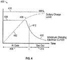
- the controller 216 is operable to determine when to charge the battery system 250 through the power input 252 and when to charge the battery system 250 through the generator 212. Switching between charging sources while on the ground can enable the hybrid electric aircraft 200 to depart from a gate before the battery system 250 is fully charged. Upon reaching a partially charged state (e.g., a first charge level) at the gate, the generator 212 can be used to continue/complete charging while the hybrid electric aircraft 200 is in a taxi state, where the gas turbine engine 20 is operating at idle. This is referred to as "topping off' the charge of the battery system 250 and is graphically depicted in the example plot 400 of FIG.
- a partially charged state e.g., a first charge level
- the first charge level 408 is an inflection point where the charging rate of the battery system 250 substantially decreases, which may occur at about eighty percent of a full charge level 416 (e.g., where a full charge level is considered as about 100%).
- a second charging current 410 indicates a maximum or desired charging current to continue charging after crossing the first charge level 408 can decay non-linearly below the first charging current 404.
- a charging source transition 412 from the gate charging 406 to taxi charging 414 can occur after the first charge level 408 such that a lower level of current can be provided by the generator 212 as the second charging current 410 during taxi charging 414.
- the battery charge level 402 can continue to increase towards the full charge level 416 as the hybrid electric aircraft 200 remains in a taxi state performing taxi charging 414 until the battery charge level 402 reaches the full charge level 416 or the hybrid electric aircraft 200 transitions to an off-idle throttle state.
- the off-idle throttle state refers to throttle movement that moves off a demand to operate the gas turbine engine 20 at idle.
- a threshold for confirming that the off-idle throttle state has been reached can be established for any desired power setting level above idle through takeoff power, for example.
- the generator 212 can transition to a motor mode during takeoff or when throttle is otherwise moved off-idle to provide supplemental rotational force to the shaft 206.
- supplemental or replacement current can be provided for battery charging through the auxiliary power input 254. Alternate transition points and operational states to support charging of the battery system 250 are contemplated.
- FIG. 3 is a schematic diagram of a dual rotor system 301 as part of a hybrid electric aircraft 300 according to an embodiment.
- the dual rotor system 301 includes a first rotor system 302A and a second rotor system 302B, which may be an embodiment of the gas turbine engine 20 of FIG. 1 .
- the first rotor system 302A can be the low speed spool 30 of the gas turbine engine 20
- the second rotor system 302B can be the high speed spool 32 of the gas turbine engine 20.
- the first rotor system 302A can include a first compressor section 204A and a first turbine section 208A operably coupled to a first shaft 206A.
- the second rotor system 302B can include a second compressor section 204B and a second turbine section 208B operably coupled to a second shaft 206B, where the second shaft 206B is concentrically arranged with respect to the first shaft 206A.
- the first compressor section 204A can be equivalent to the low pressure compressor 44
- the first shaft 206A can be equivalent to the inner shaft 40
- the first turbine section 208A can be equivalent to the low pressure turbine 46 of FIG. 1
- the second compressor section 204B can be equivalent to the high pressure compressor 52
- the second shaft 206B can be equivalent to the outer shaft 50
- the second turbine section 208B can be equivalent to the high pressure turbine 54 of FIG. 1 .
- a battery charging system 310 includes a generator 212 operably coupled to converter electronics 214 and an electric motor 312 driven by drive electronics 314.
- a first set of one or more rotor system sensors 218A may be associated with the first rotor system 302A, and a second set of one or more rotor system sensors 218B may be associated with the second rotor system 302B.
- the converter electronics 214 can control charging of the battery system 250 responsive to a controller 216 that may receive sensor data from the first set of one or more rotor system sensors 218A and the second set of one or more rotor system sensors 218B.
- the controller 216 may control the electric motor 312 through the drive electronics 314 responsive to sensor data from the first set of one or more rotor system sensors 218A and/or the second set of one or more rotor system sensors 218B.
- the controller 216 is further subdivided as two or more separate controls, for instance, where a separate instance of the controller 216 is provided for each of the generator 212 and the electric motor 312.
- the generator 212 (when operated in a motor mode) and the electric motor 312 can be independently controlled to each supply a supplemental motive force to the respective shafts 206A, 206B, where fuel combustion in the combustor section 26 ( FIG.
- the generator 212 and the electric motor 312 can each be configured in either a generator mode or a motor mode.
- the generator 212 can be operably coupled to the first shaft 206A using a direct coupling, while the electric motor 312 can be operably coupled to the second shaft 206B using a geared interface 330.
- a first disconnect 240A such as a clutch, can be positioned between the generator 212 and a portion of the first shaft 206A, and a second disconnect 240B can be positioned between the electric motor 312 and a portion of the second shaft 206B.
- the geared interface 330 can include, for instance, a motor gear 333 coupled to a motor shaft 335 driven by the electric motor 312 and a rotor gear 337 coupled to the second shaft 206B. While the example of FIG.
- both of the generator 212 and electric motor 312 can be directly or indirectly coupled to corresponding first and second shafts 206A, 206B.
- the generator 212 may be indirectly coupled through a tower shaft to the first shaft 206A, while the electric motor 312 is directly coupled to the second shaft 206B.
- the coupling locations of the generator 212 and electric motor 312 to the first and second shafts 206A, 206B can vary, and the coupling locations depicted in FIG. 3 are merely one example.
- the propulsion system use 256 can be to provide electrical power to the electric motor 312 and/or provide electrical power to the generator 212 when operating in a motor mode.
- the controller 216 may disable or provide limited current to the electric motor 312 while the battery system 250 is being charged by one or more of the generator 212, the power input 252, and/or the auxiliary power input 254. Electric current produced by the generator 212 above a level needed to charge the battery system 250 may be provided to other on-board uses.
- FIG. 5 is a flow chart illustrating a method 500 for hybrid electric aircraft battery charging, in accordance with an embodiment.
- the method 500 may be performed, for example, by the battery charging systems 210, 310 of FIGS. 2 and 3 .
- the method 500 is described primarily with respect to the battery charging system 210 of FIG. 2 ; however, it will be understood that the method 500 can be performed on other configurations, such as the battery charging system 310 of FIG. 3 as well as other configurations (not depicted).
- the controller 216 can charge the battery system 250 up to a first charge level 408 based on receiving a first charging current 404 at a power input 252.
- the controller 216 can monitor an operational status of the gas turbine engine 20, for instance, based on sensor data from rotor system sensors 218.
- the controller 216 can charge the battery system 250 at a second charging current 410 received from the generator 212 responsive to determining that the gas turbine engine 20 is in a taxi state, where the second charging current 410 is less than the first charging current 404.
- the controller 216 can be configured to continue to charging the battery system 250 beyond the first charge level 408 based on detecting that the second charging current 410 is available at the power input 252 after reaching the first charge level 408.
- the controller 216 can halt charging of the battery system 250 based on detecting a transition of the gas turbine engine 20 from the taxi state to an off-idle throttle state or upon reaching a full charge level of the battery system 250.
- Engine spool rotational speed, throttle commands, and other inputs received at the controller 216 can be used to determine the operational status of the gas turbine engine 20.
- the battery system 250 can be used during flight to power one or more electrical systems of the hybrid electric aircraft 200, such as the propulsion system use 256 and/or other uses.
- the gas turbine engine 20 can be operated with a higher engine power setting above idle to increase charging rate and reduce idle thrust via power extraction in the taxi state through power transfer to the generator 212. This can result in a lower exhaust gas temperature due to improved component efficiency at idle as a result of operation of the component in a higher speed range. Thrust at idle can be kept low at the higher engine power setting by performing power extraction from the low speed spool 30. Alternatively, power extraction can be performed from the high speed spool 32.
- the reduced second charging current 410 below the first charging current 404 can enable the use of a smaller size of the generator 212 than would otherwise be needed to reach the first charging current 404.
Abstract
Description
- The subject matter disclosed herein generally relates to battery charging systems and, more particularly, to a method and apparatus for hybrid electric aircraft battery charging.
- Hybrid electric aircraft use electricity to provide a portion of the power needed for propulsion by converting electricity into a propulsive force. Battery storage capacity on an aircraft can be limited due to weight and size restrictions. The process of recharging batteries used by a hybrid electric aircraft can be time consuming, particularly for high-energy density batteries.
- According to one embodiment, a battery charging system for a hybrid electric aircraft is provided. The battery charging system includes a generator, a battery system, and a controller. The controller is operable to charge the battery system up to a first charge level based on receiving a first charging current at a power input. An operational status of a gas turbine engine of the hybrid electric aircraft is monitored. The battery system is charged at a second charging current received from the generator driven by the gas turbine engine responsive to determining that the gas turbine engine is in a taxi state, where the second charging current is less than the first charging current. Charging of the battery system is halted based on detecting a transition of the gas turbine engine from the taxi state to an off-idle throttle state.
- In addition to one or more of the features described above or below, or as an alternative, further embodiments may include where the first charging current is received from a ground-based power source through the power input.
- In addition to one or more of the features described above or below, or as an alternative, further embodiments may include where the generator is operably coupled to a spool of the gas turbine engine.
- In addition to one or more of the features described above or below, or as an alternative, further embodiments may include where the gas turbine engine is operated with a higher engine power setting above idle to increase charging rate and reduce idle thrust via power extraction in the taxi state.
- In addition to one or more of the features described above or below, or as an alternative, further embodiments may include where the generator is a motor-generator operable in a generator mode to charge the battery system and in a motor mode to provide supplemental rotation force to the gas turbine engine.
- In addition to one or more of the features described above or below, or as an alternative, further embodiments may include where the battery system is used during flight to power one or more electrical systems of the hybrid electric aircraft.
- In addition to one or more of the features described above or below, or as an alternative, further embodiments may include where the controller is configured to continue to charge the battery system beyond the first charge level based on detecting that the second charging current is available at the power input after reaching the first charge level.
- According to another embodiment, a propulsion system includes a gas turbine engine, a generator operably coupled to the gas turbine engine, a battery system, and a controller. The controller is operable to charge the battery system up to a first charge level based on receiving a first charging current at a power input, monitor an operational status of the gas turbine engine, and charge the battery system at a second charging current received from the generator responsive to determining that the gas turbine engine is in a taxi state, where the second charging current is less than the first charging current. Charging of the battery system can be halted based on detecting a transition of the gas turbine engine from the taxi state to an off-idle throttle state or upon reaching a full charge level of the battery system.
- According to another embodiment, a method of charging a battery system of a hybrid electric aircraft includes charging the battery system up to a first charge level based on receiving a first charging current at a power input and monitoring an operational status of a gas turbine engine of the hybrid electric aircraft. The battery system is charged at a second charging current received from the generator driven by the gas turbine engine responsive to determining that the gas turbine engine is in a taxi state, where the second charging current is less than the first charging current. Charging of the battery system can be halted based on detecting a transition of the gas turbine engine from the taxi state to an off-idle throttle state.
- A technical effect of the apparatus, systems and methods is achieved by providing a recharging sequence to selectively recharge batteries of a hybrid electric aircraft during ground-based operations as described herein.
- The following descriptions should not be considered limiting in any way. With reference to the accompanying drawings, like elements are numbered alike:
-
FIG. 1 is a partial cross-sectional illustration of a gas turbine engine, in accordance with an embodiment of the disclosure; -
FIG. 2 is a schematic diagram of a battery charging system for a hybrid electric aircraft, in accordance with an embodiment of the disclosure; -
FIG. 3 is a schematic diagram of a battery charging system for a hybrid electric aircraft, in accordance with an embodiment of the disclosure; -
FIG. 4 is a battery charging plot of electrical current versus time, in accordance with an embodiment of the disclosure; and -
FIG. 5 is a flow chart illustrating a method, in accordance with an embodiment of the disclosure. - A detailed description of one or more embodiments of the disclosed apparatus and method are presented herein by way of exemplification and not limitation with reference to the Figures.
-
FIG. 1 schematically illustrates agas turbine engine 20. Thegas turbine engine 20 is disclosed herein as a two-spool turbofan that generally incorporates afan section 22, acompressor section 24, acombustor section 26 and aturbine section 28. Thefan section 22 drives air along a bypass flow path B in a bypass duct, while thecompressor section 24 drives air along a core flow path C for compression and communication into thecombustor section 26 then expansion through theturbine section 28. Although depicted as a two-spool turbofan gas turbine engine in the disclosed non-limiting embodiment, it should be understood that the concepts described herein are not limited to use with two-spool turbofans as the teachings may be applied to other types of turbine engines including three-spool architectures. - The
exemplary engine 20 generally includes alow speed spool 30 and ahigh speed spool 32 mounted for rotation about an engine central longitudinal axis A relative to an enginestatic structure 36 viaseveral bearing systems 38. It should be understood thatvarious bearing systems 38 at various locations may alternatively or additionally be provided, and the location ofbearing systems 38 may be varied as appropriate to the application. - The
low speed spool 30 generally includes aninner shaft 40 that interconnects afan 42, alow pressure compressor 44 and alow pressure turbine 46. Theinner shaft 40 is connected to thefan 42 through a speed change mechanism, which in exemplarygas turbine engine 20 is illustrated as a gearedarchitecture 48 to drive thefan 42 at a lower speed than thelow speed spool 30. Thehigh speed spool 32 includes anouter shaft 50 that interconnects ahigh pressure compressor 52 andhigh pressure turbine 54. Acombustor 56 is arranged inexemplary gas turbine 20 between thehigh pressure compressor 52 and thehigh pressure turbine 54. An enginestatic structure 36 is arranged generally between thehigh pressure turbine 54 and thelow pressure turbine 46. The enginestatic structure 36 further supports bearingsystems 38 in theturbine section 28. Theinner shaft 40 and theouter shaft 50 are concentric and rotate viabearing systems 38 about the engine central longitudinal axis A which is collinear with their longitudinal axes. - The core airflow is compressed by the
low pressure compressor 44 then thehigh pressure compressor 52, mixed and burned with fuel in thecombustor 56, then expanded over thehigh pressure turbine 54 andlow pressure turbine 46. Theturbines low speed spool 30 andhigh speed spool 32 in response to the expansion. It will be appreciated that each of the positions of thefan section 22,compressor section 24,combustor section 26,turbine section 28, and fandrive gear system 48 may be varied. For example,gear system 48 may be located aft ofcombustor section 26 or even aft ofturbine section 28, andfan section 22 may be positioned forward or aft of the location ofgear system 48. - The
engine 20 in one example is a high-bypass geared aircraft engine. In a further example, theengine 20 bypass ratio is greater than about six (6), with an example embodiment being greater than about ten (10), the gearedarchitecture 48 is an epicyclic gear train, such as a planetary gear system or other gear system, with a gear reduction ratio of greater than about 2.3 and thelow pressure turbine 46 has a pressure ratio that is greater than about five. In one disclosed embodiment, theengine 20 bypass ratio is greater than about ten (10:1), the fan diameter is significantly larger than that of thelow pressure compressor 44, and thelow pressure turbine 46 has a pressure ratio that is greater than about five 5:1.Low pressure turbine 46 pressure ratio is pressure measured prior to inlet oflow pressure turbine 46 as related to the pressure at the outlet of thelow pressure turbine 46 prior to an exhaust nozzle. The gearedarchitecture 48 may be an epicycle gear train, such as a planetary gear system or other gear system, with a gear reduction ratio of greater than about 2.3:1. It should be understood, however, that the above parameters are only exemplary of one embodiment of a geared architecture engine and that the present disclosure is applicable to other gas turbine engines including direct drive turbofans. - A significant amount of thrust is provided by the bypass flow B due to the high bypass ratio. The
fan section 22 of theengine 20 is designed for a particular flight condition--typically cruise at about 0.8Mach and about 35,000 feet (10,668 meters). The flight condition of 0.8 Mach and 35,000 ft (10,668 meters), with the engine at its best fuel consumption--also known as "bucket cruise Thrust Specific Fuel Consumption ('TSFC')"--is the industry standard parameter of lbm of fuel being burned divided by lbf of thrust the engine produces at that minimum point. "Low fan pressure ratio" is the pressure ratio across the fan blade alone, without a Fan Exit Guide Vane ("FEGV") system. The low fan pressure ratio as disclosed herein according to one non-limiting embodiment is less than about 1.45. "Low corrected fan tip speed" is the actual fan tip speed in ft/sec divided by an industry standard temperature correction of [(Tram °R)/(518.7 °R)]0.5. The "Low corrected fan tip speed" as disclosed herein according to one non-limiting embodiment is less than about 1150 ft/second (350.5 m/sec). - While the example of
FIG. 1 illustrates one example of thegas turbine engine 20, it will be understood that any number of spools, inclusion or omission of thegear system 48, and/or other elements and subsystems are contemplated. Further, rotor systems described herein can be used in a variety of applications and need not be limited to gas turbine engines for aircraft applications. For example, rotor systems can be included in power generation systems, which may be ground-based as a fixed position or mobile system, and other such applications. -
FIG. 2 illustrates arotor system 202 that includes at least onecompressor section 204 and at least oneturbine section 208 operably coupled to ashaft 206 as part of a hybridelectric aircraft 200. Therotor system 202 can be a spool of thegas turbine engine 20 ofFIG. 1 , such as thelow speed spool 30 or thehigh speed spool 32. For example, when embodied as thelow speed spool 30, the at least onecompressor section 204 can be equivalent to thelow pressure compressor 44, theshaft 206 can be equivalent to theinner shaft 40, and the at least oneturbine section 208 can be equivalent to thelow pressure turbine 46 ofFIG. 1 . When embodied as thehigh speed spool 32, the at least onecompressor section 204 can be equivalent to thehigh pressure compressor 52, theshaft 206 can be equivalent to theouter shaft 50, and the at least oneturbine section 208 can be equivalent to thehigh pressure turbine 54 ofFIG. 1 . - In the example of
FIG. 2 , abattery charging system 210 is operably coupled to therotor system 202. Thebattery charging system 210 includes agenerator 212 operably coupled to theshaft 206. In the example ofFIG. 2 , a gearedinterface 230 operably couples thegenerator 212 to theshaft 206. The gearedinterface 230 can include, for instance, anauxiliary gear 233 coupled to anauxiliary shaft 235 driven by thegenerator 212. The gearedinterface 230 can also include arotor gear 237 coupled to theshaft 206. Theauxiliary gear 233 and therotor gear 237 can each be beveled gears. Theauxiliary shaft 235 can be a tower shaft that enables thegenerator 212 to be separated at a greater distance from therotor system 202 than direct coupling to theshaft 206 would provide. Further separation of thegenerator 212 from therotor system 202 can improve accessibility to thegenerator 212 for servicing and may reduce heating effects of therotor system 202 on the generator 212 (e.g., due to fuel combustion). Adisconnect 240, such as a clutch, can be positioned between thegenerator 212 and a portion of theshaft 206 such that thegenerator 212 can be selectively engaged and disengaged to rotate with rotation of theshaft 206. In alternate embodiments, thegenerator 212 is operably coupled to theshaft 206 absent the geared interface 230 (e.g., direct coupling). - The
battery charging system 210 also includesconverter electronics 214 operable to condition current from thegenerator 212. In some embodiments, thegenerator 212 is a motor-generator configurable in a generator mode to charge abattery system 250 and in a motor mode to provide supplemental rotation force to therotor system 202 ofgas turbine engine 20 ofFIG. 1 . Thegenerator 212 can include conventional generator/motor components, such as a rotor and stator, including a plurality of windings and/or permanent magnets. Theconverter electronics 214 can also include conventional current control electronics, such as filters, switching components, rectifiers, inverters, voltage converters, and the like. Thegenerator 212 can perform as a variable frequency generator in a generator mode due to speed fluctuations of rotation of theshaft 206, which may be primarily driven by the at least oneturbine section 208. Alternatively, a frequency normalizing component can interface with thegenerator 212 to produce a constant frequency output (e.g., through theconverter electronics 214 or as a mechanical interface between thegenerator 212 and the shaft 206). In some embodiments, thegenerator 212 may be operable as a starter motor to partially or completely power rotation of theshaft 206 in a starting mode of operation (e.g., to start thegas turbine engine 20 ofFIG. 1 ) and/or can provide supplemental power to theshaft 206 during various flight phases of the hybridelectric aircraft 200. Other uses and functions for thegenerator 212 are contemplated. - The
converter electronics 214 can control charging of thebattery system 250 responsive to acontroller 216. Thecontroller 216 can enable a flow of a charging current from thegenerator 212 or apower input 252 to charge thebattery system 250 as regulated and conditioned through theconverter electronics 214. Thepower input 252 can be an external input, such as power received through a plug interface while the hybridelectric aircraft 200 is on the ground at a ground-based power source, e.g., at a gate or service location. In some embodiments, theconverter electronics 214 may receive electric current from anauxiliary power input 254 to provide a supplemental or alternative power source for charging thebattery system 250. For instance, theauxiliary power input 254 may receive electric current from an auxiliary power unit (not depicted) or another instance of thegas turbine engine 20 on the hybridelectric aircraft 200. The charge stored in thebattery system 250 can provide an electric current for apropulsion system use 256, which may include powering one or more electric motors of the hybridelectric aircraft 200 during various operational states and/or providing power to thegenerator 212 when operating in a motor mode, for instance, to assist in driving rotation ofshaft 206. Thepropulsion system use 256 can be part of thegas turbine engine 20 that includes therotor system 202 or another aircraft system, such as another instance of thegas turbine engine 20 on the hybridelectric aircraft 200. - In embodiments, the
controller 216 of thebattery charging system 210 can monitor one or morerotor system sensors 218 while therotor system 202 is rotating. Therotor system sensors 218 can be any type or combination of sensors operable to measure aspects of the motion of therotor system 202. For example, therotor system sensors 218 can include one or more accelerometers, speed sensors, torque sensors, and the like. Therotor system sensors 218 can be existing sensors used for controlling thegas turbine engine 20. Thecontroller 216 can control a charging of thebattery system 250, for instance, by selecting the source of electric current received through theconverter electronics 214. Data collected from therotor system sensors 218 can be used to determine an operational status of agas turbine engine 20 ofFIG. 2 . Alternatively, the operational status of agas turbine engine 20 can be received as a signal or message from an alternate source, such as an engine system or aircraft communication bus. Thecontroller 216 may also control other system aspects, such as controlling operation of thegas turbine engine 20 ofFIG. 1 . For example, thecontroller 216 can be integrally formed or otherwise in communication with a full authority digital engine control (FADEC) of thegas turbine engine 20. Therotor system sensors 218 need not be directly coupled to thecontroller 216, as sensor data or sensor-derived data can be observed or determined by another control (e.g., a FADEC) and provided to thecontroller 216. In embodiments, thecontroller 216 can include aprocessing system 220, amemory system 222, and an input/output interface 224. Theprocessing system 220 can include any type or combination of central processing unit (CPU), including one or more of: a microprocessor, a digital signal processor (DSP), a microcontroller, an application specific integrated circuit (ASIC), a field programmable gate array (FPGA), or the like. Thememory system 222 can store data and instructions that are executed by theprocessing system 220. In embodiments, thememory system 222 may include random access memory (RAM), read only memory (ROM), or other electronic, optical, magnetic, or any other computer readable medium onto which is stored data and algorithms in a non-transitory form. The input/output interface 224 is configured to collect sensor data from the one or morerotor system sensors 218 and interface with theconverter electronics 214 and/or other systems (not depicted). - The
controller 216 is operable to determine when to charge thebattery system 250 through thepower input 252 and when to charge thebattery system 250 through thegenerator 212. Switching between charging sources while on the ground can enable the hybridelectric aircraft 200 to depart from a gate before thebattery system 250 is fully charged. Upon reaching a partially charged state (e.g., a first charge level) at the gate, thegenerator 212 can be used to continue/complete charging while the hybridelectric aircraft 200 is in a taxi state, where thegas turbine engine 20 is operating at idle. This is referred to as "topping off' the charge of thebattery system 250 and is graphically depicted in theexample plot 400 ofFIG. 4 , where abattery charge level 402 increases more rapidly at a first charging current 404 during gate charging 406 from thepower input 252 and slows upon reaching afirst charge level 408. In the example ofFIG. 4 , thefirst charge level 408 is an inflection point where the charging rate of thebattery system 250 substantially decreases, which may occur at about eighty percent of a full charge level 416 (e.g., where a full charge level is considered as about 100%). A second charging current 410 indicates a maximum or desired charging current to continue charging after crossing thefirst charge level 408 can decay non-linearly below the first charging current 404. A chargingsource transition 412 from the gate charging 406 to taxi charging 414 can occur after thefirst charge level 408 such that a lower level of current can be provided by thegenerator 212 as the second charging current 410 during taxi charging 414. Thebattery charge level 402 can continue to increase towards thefull charge level 416 as the hybridelectric aircraft 200 remains in a taxi state performing taxi charging 414 until thebattery charge level 402 reaches thefull charge level 416 or the hybridelectric aircraft 200 transitions to an off-idle throttle state. During the off-idle throttle state, charging can be halted to reduce loading on thegas turbine engine 20. The off-idle throttle state refers to throttle movement that moves off a demand to operate thegas turbine engine 20 at idle. A threshold for confirming that the off-idle throttle state has been reached can be established for any desired power setting level above idle through takeoff power, for example. In some embodiments, thegenerator 212 can transition to a motor mode during takeoff or when throttle is otherwise moved off-idle to provide supplemental rotational force to theshaft 206. Further, supplemental or replacement current can be provided for battery charging through theauxiliary power input 254. Alternate transition points and operational states to support charging of thebattery system 250 are contemplated. -
FIG. 3 is a schematic diagram of adual rotor system 301 as part of a hybridelectric aircraft 300 according to an embodiment. Thedual rotor system 301 includes afirst rotor system 302A and asecond rotor system 302B, which may be an embodiment of thegas turbine engine 20 ofFIG. 1 . For instance, thefirst rotor system 302A can be thelow speed spool 30 of thegas turbine engine 20, and thesecond rotor system 302B can be thehigh speed spool 32 of thegas turbine engine 20. Thefirst rotor system 302A can include afirst compressor section 204A and afirst turbine section 208A operably coupled to afirst shaft 206A. Thesecond rotor system 302B can include asecond compressor section 204B and asecond turbine section 208B operably coupled to asecond shaft 206B, where thesecond shaft 206B is concentrically arranged with respect to thefirst shaft 206A. With respect to thegas turbine engine 20 ofFIG. 1 , thefirst compressor section 204A can be equivalent to thelow pressure compressor 44, thefirst shaft 206A can be equivalent to theinner shaft 40, and thefirst turbine section 208A can be equivalent to thelow pressure turbine 46 ofFIG. 1 . Similarly, thesecond compressor section 204B can be equivalent to thehigh pressure compressor 52, thesecond shaft 206B can be equivalent to theouter shaft 50, and thesecond turbine section 208B can be equivalent to thehigh pressure turbine 54 ofFIG. 1 . - In the example of
FIG. 3 , abattery charging system 310 includes agenerator 212 operably coupled toconverter electronics 214 and anelectric motor 312 driven bydrive electronics 314. A first set of one or morerotor system sensors 218A may be associated with thefirst rotor system 302A, and a second set of one or morerotor system sensors 218B may be associated with thesecond rotor system 302B. Theconverter electronics 214 can control charging of thebattery system 250 responsive to acontroller 216 that may receive sensor data from the first set of one or morerotor system sensors 218A and the second set of one or morerotor system sensors 218B. Thecontroller 216 may control theelectric motor 312 through thedrive electronics 314 responsive to sensor data from the first set of one or morerotor system sensors 218A and/or the second set of one or morerotor system sensors 218B. In other embodiments, thecontroller 216 is further subdivided as two or more separate controls, for instance, where a separate instance of thecontroller 216 is provided for each of thegenerator 212 and theelectric motor 312. The generator 212 (when operated in a motor mode) and theelectric motor 312 can be independently controlled to each supply a supplemental motive force to therespective shafts FIG. 1 ) can provide a primary motive force for thefirst rotor system 302A as thelow speed spool 30 and for thesecond rotor system 302B as thehigh speed spool 32. In some embodiments, thegenerator 212 and theelectric motor 312 can each be configured in either a generator mode or a motor mode. - The
generator 212 can be operably coupled to thefirst shaft 206A using a direct coupling, while theelectric motor 312 can be operably coupled to thesecond shaft 206B using a gearedinterface 330. Afirst disconnect 240A, such as a clutch, can be positioned between thegenerator 212 and a portion of thefirst shaft 206A, and asecond disconnect 240B can be positioned between theelectric motor 312 and a portion of thesecond shaft 206B. The gearedinterface 330 can include, for instance, amotor gear 333 coupled to amotor shaft 335 driven by theelectric motor 312 and arotor gear 337 coupled to thesecond shaft 206B. While the example ofFIG. 3 depicts thebattery charging system 310 with thegenerator 212 andelectric motor 312 in different coupling configurations, it will be understood that both of thegenerator 212 andelectric motor 312 can be directly or indirectly coupled to corresponding first andsecond shafts generator 212 may be indirectly coupled through a tower shaft to thefirst shaft 206A, while theelectric motor 312 is directly coupled to thesecond shaft 206B. Further, the coupling locations of thegenerator 212 andelectric motor 312 to the first andsecond shafts FIG. 3 are merely one example. - In the example of
FIG. 3 , thepropulsion system use 256 can be to provide electrical power to theelectric motor 312 and/or provide electrical power to thegenerator 212 when operating in a motor mode. In embodiments, thecontroller 216 may disable or provide limited current to theelectric motor 312 while thebattery system 250 is being charged by one or more of thegenerator 212, thepower input 252, and/or theauxiliary power input 254. Electric current produced by thegenerator 212 above a level needed to charge thebattery system 250 may be provided to other on-board uses. - Referring now to
FIG. 5 with continued reference toFIGS. 1-4 ,FIG. 5 is a flow chart illustrating amethod 500 for hybrid electric aircraft battery charging, in accordance with an embodiment. Themethod 500 may be performed, for example, by thebattery charging systems FIGS. 2 and3 . For purposes of explanation, themethod 500 is described primarily with respect to thebattery charging system 210 ofFIG. 2 ; however, it will be understood that themethod 500 can be performed on other configurations, such as thebattery charging system 310 ofFIG. 3 as well as other configurations (not depicted). - At
block 502, thecontroller 216 can charge thebattery system 250 up to afirst charge level 408 based on receiving a first charging current 404 at apower input 252. Atblock 504, thecontroller 216 can monitor an operational status of thegas turbine engine 20, for instance, based on sensor data fromrotor system sensors 218. Atblock 506, thecontroller 216 can charge thebattery system 250 at a second charging current 410 received from thegenerator 212 responsive to determining that thegas turbine engine 20 is in a taxi state, where the second charging current 410 is less than the first charging current 404. Thecontroller 216 can be configured to continue to charging thebattery system 250 beyond thefirst charge level 408 based on detecting that the second charging current 410 is available at thepower input 252 after reaching thefirst charge level 408. Atblock 508, thecontroller 216 can halt charging of thebattery system 250 based on detecting a transition of thegas turbine engine 20 from the taxi state to an off-idle throttle state or upon reaching a full charge level of thebattery system 250. Engine spool rotational speed, throttle commands, and other inputs received at thecontroller 216 can be used to determine the operational status of thegas turbine engine 20. Thebattery system 250 can be used during flight to power one or more electrical systems of the hybridelectric aircraft 200, such as thepropulsion system use 256 and/or other uses. - In embodiments, the
gas turbine engine 20 can be operated with a higher engine power setting above idle to increase charging rate and reduce idle thrust via power extraction in the taxi state through power transfer to thegenerator 212. This can result in a lower exhaust gas temperature due to improved component efficiency at idle as a result of operation of the component in a higher speed range. Thrust at idle can be kept low at the higher engine power setting by performing power extraction from thelow speed spool 30. Alternatively, power extraction can be performed from thehigh speed spool 32. The reduced second charging current 410 below the first charging current 404 can enable the use of a smaller size of thegenerator 212 than would otherwise be needed to reach the first charging current 404. - While the above description has described the flow process of
FIG. 5 in a particular order, it should be appreciated that unless otherwise specifically required in the attached claims that the ordering of the steps may be varied. - The term "about" is intended to include the degree of error associated with measurement of the particular quantity based upon the equipment available at the time of filing the application.
- The terminology used herein is for the purpose of describing particular embodiments only and is not intended to be limiting of the present disclosure. As used herein, the singular forms "a", "an" and "the" are intended to include the plural forms as well, unless the context clearly indicates otherwise. It will be further understood that the terms "comprises" and/or "comprising," when used in this specification, specify the presence of stated features, integers, steps, operations, elements, and/or components, but do not preclude the presence or addition of one or more other features, integers, steps, operations, element components, and/or groups thereof.
- While the present disclosure has been described with reference to an exemplary embodiment or embodiments, it will be understood by those skilled in the art that various changes may be made and equivalents may be substituted for elements thereof without departing from the scope of the present disclosure. In addition, many modifications may be made to adapt a particular situation or material to the teachings of the present disclosure without departing from the essential scope thereof. Therefore, it is intended that the present disclosure not be limited to the particular embodiment disclosed as the best mode contemplated for carrying out this present disclosure, but that the present disclosure will include all embodiments falling within the scope of the claims.
- The following clauses set out features of the invention which may or may not presently be claimed in this application, but which may form the basis for future amendment or a divisional application.
- 1. A battery charging system for a hybrid electric aircraft, the battery charging system comprising:
- a generator;
- a battery system; and
- a controller operable to:
- charge the battery system up to a first charge level based on receiving a first charging current at a power input;
- monitor an operational status of a gas turbine engine of the hybrid electric aircraft;
- charge the battery system at a second charging current received from the generator driven by the gas turbine engine responsive to determining that the gas turbine engine is in a taxi state, wherein the second charging current is less than the first charging current; and
- halt charging of the battery system based on detecting a transition of the gas turbine engine from the taxi state to an off-idle throttle state.
- 2. The battery charging system of clause 1, wherein the first charging current is received from a ground-based power source through the power input.
- 3. The battery charging system of clause 1, wherein the generator is operably coupled to a spool of the gas turbine engine.
- 4. The battery charging system of clause 1, wherein the gas turbine engine is operated with a higher engine power setting above idle to increase charging rate and reduce idle thrust via power extraction in the taxi state.
- 5. The battery charging system of clause 1, wherein the generator is a motor-generator operable in a generator mode to charge the battery system and in a motor mode to provide supplemental rotation force to the gas turbine engine.
- 6. The battery charging system of clause 1, wherein the battery system is used during flight to power one or more electrical systems of the hybrid electric aircraft.
- 7. The battery charging system of clause 1, wherein the controller is configured to continue to charge the battery system beyond the first charge level based on detecting that the second charging current is available at the power input after reaching the first charge level.
- 8. A propulsion system comprising:
- a gas turbine engine;
- a generator operably coupled to the gas turbine engine;
- a battery system; and
- a controller operable to:
- charge the battery system up to a first charge level based on receiving a first charging current at a power input;
- monitor an operational status of the gas turbine engine;
- charge the battery system at a second charging current received from the generator responsive to determining that the gas turbine engine is in a taxi state, wherein the second charging current is less than the first charging current; and
- halt charging of the battery system based on detecting a transition of the gas turbine engine from the taxi state to an off-idle throttle state.
- 9. The propulsion system of clause 8, wherein the first charging current is received from a ground-based power source through the power input.
- 10. The propulsion system of clause 8, wherein the generator is operably coupled to a spool of the gas turbine engine.
- 11. The propulsion system of clause 8, wherein the gas turbine engine is operated with a higher engine power setting above idle to increase charging rate and reduce idle thrust via power extraction in the taxi state.
- 12. The propulsion system of clause 8, wherein the generator is a motor-generator operable in a generator mode to charge the battery system and in a motor mode to provide supplemental rotation force to the gas turbine engine based on electric current from the battery system.
- 13. The propulsion system of clause 8, wherein the battery system is used during flight to power one or more electrical systems.
- 14. The propulsion system of clause 8, wherein the controller is configured to continue to charge the battery system beyond the first charge level based on detecting that the second charging current is available at the power input after reaching the first charge level.
- 15. A method of charging a battery system of a hybrid electric aircraft, the method comprising:
- charging the battery system up to a first charge level based on receiving a first charging current at a power input;
- monitoring an operational status of a gas turbine engine of the hybrid electric aircraft;
- charging the battery system at a second charging current received from the generator driven by the gas turbine engine responsive to determining that the gas turbine engine is in a taxi state, wherein the second charging current is less than the first charging current; and
- halting the charging of the battery system based on detecting a transition of the gas turbine engine from the taxi state to an off-idle throttle state.
- 16. The method of clause 15, wherein the first charging current is received from a ground-based power source through the power input.
- 17. The method of clause 15, further comprising:
operating the gas turbine engine with a higher engine power setting above idle to increase charging rate and reduce idle thrust via power extraction in the taxi state. - 18. The method of clause 15, wherein the generator is a motor-generator operable in a generator mode to charge the battery system and in a motor mode to provide supplemental rotation force to the gas turbine engine.
- 19. The method of clause 15, wherein the battery system is used during flight to power one or more electrical systems of the hybrid electric aircraft.
- 20. The method of clause 15, further comprising:
continuing to charge the battery system beyond the first charge level based on detecting that a second charging current is available at the power input after reaching the first charge level.
Claims (14)
- A battery charging system (210; 310) for a hybrid electric aircraft (200; 300), the battery charging system comprising:a generator (212);a battery system (250); anda controller (216) operable to:charge the battery system (250) up to a first charge level (408) based on receiving a first charging current (404) at a power input (252);monitor an operational status of a gas turbine engine (20) of the hybrid electric aircraft;charge the battery system (250) at a second charging current (410) received from the generator (212) driven by the gas turbine engine (20) responsive to determining that the gas turbine engine is in a taxi state, wherein the second charging current (410) is less than the first charging current (404); andhalt charging of the battery system (250) based on detecting a transition (412) of the gas turbine engine from the taxi state to an off-idle throttle state.
- The battery charging system of claim 1, wherein the first charging current (404) is received from a ground-based power source through the power input (252).
- The battery charging system of claim 1 or 2, wherein the generator (212) is operably coupled to a spool (206; 206A) of the gas turbine engine (20).
- The battery charging system of claim 1, 2 or 3, wherein the gas turbine engine (20) is operated with a higher engine power setting above idle to increase charging rate and reduce idle thrust via power extraction in the taxi state.
- The battery charging system of any preceding claim, wherein the generator (212) is a motor-generator operable in a generator mode to charge the battery system (250) and in a motor mode to provide supplemental rotation force to the gas turbine engine (20).
- The battery charging system of any preceding claim, wherein the battery system (250) is used during flight to power one or more electrical systems of the hybrid electric aircraft.
- The battery charging system of any preceding claim, wherein the controller (216) is configured to continue to charge the battery system beyond the first charge level (408) based on detecting that the second charging current (410) is available at the power input after reaching the first charge level.
- A propulsion system comprising:a gas turbine engine (20); anda battery charging system of any preceding claim wherein the generator is operably coupled to the gas turbine engine.
- A method of charging a battery system (250) of a hybrid electric aircraft (200; 300), the method comprising:charging (502) the battery system up to a first charge level (408) based on receiving a first charging current (404) at a power input (252);monitoring (504) an operational status of a gas turbine engine (20) of the hybrid electric aircraft;charging (506) the battery system (250) at a second charging current (410) received from the generator (212) driven by the gas turbine engine (20) responsive to determining that the gas turbine engine is in a taxi state, wherein the second charging current (410) is less than the first charging current (404); andhalting (508) the charging of the battery system (250) based on detecting a transition (412) of the gas turbine engine from the taxi state to an off-idle throttle state.
- The method of claim 9, wherein the first charging current (404) is received from a ground-based power source through the power input (252).
- The method of claim 9 or 10, further comprising:
operating the gas turbine engine (20) with a higher engine power setting above idle to increase charging rate and reduce idle thrust via power extraction in the taxi state. - The method of claim 9, 10 or 11, wherein the generator (212) is a motor-generator operable in a generator mode to charge the battery system (250) and in a motor mode to provide supplemental rotation force to the gas turbine engine (20).
- The method of any of claims 9 to 12, wherein the battery system (250) is used during flight to power one or more electrical systems of the hybrid electric aircraft.
- The method of any of claims 9 to 13, further comprising:
continuing to charge the battery system (250) beyond the first charge level (408) based on detecting that a second charging current (410) is available at the power input (252) after reaching the first charge level (408).
Applications Claiming Priority (1)
| Application Number | Priority Date | Filing Date | Title |
|---|---|---|---|
| US16/104,288 US10773812B2 (en) | 2018-08-17 | 2018-08-17 | Hybrid electric aircraft battery charging |
Publications (2)
| Publication Number | Publication Date |
|---|---|
| EP3623203A1 true EP3623203A1 (en) | 2020-03-18 |
| EP3623203B1 EP3623203B1 (en) | 2022-04-06 |
Family
ID=67659014
Family Applications (1)
| Application Number | Title | Priority Date | Filing Date |
|---|---|---|---|
| EP19191993.5A Active EP3623203B1 (en) | 2018-08-17 | 2019-08-15 | Hybrid electric aircraft battery charging |
Country Status (2)
| Country | Link |
|---|---|
| US (1) | US10773812B2 (en) |
| EP (1) | EP3623203B1 (en) |
Cited By (4)
| Publication number | Priority date | Publication date | Assignee | Title |
|---|---|---|---|---|
| EP3767090A1 (en) * | 2019-07-15 | 2021-01-20 | Raytheon Technologies Corporation | Compressor operability control for hybrid electric propulsion |
| EP4082915A1 (en) * | 2021-04-30 | 2022-11-02 | Raytheon Technologies Corporation | Hybrid propulsion control system update module |
| EP4286657A1 (en) * | 2022-05-31 | 2023-12-06 | Pratt & Whitney Canada Corp. | Gas turbine engine with electric machine in engine core |
| EP4328067A1 (en) * | 2022-08-25 | 2024-02-28 | Honeywell International Inc. | Energy management of hybrid electrical systems |
Families Citing this family (14)
| Publication number | Priority date | Publication date | Assignee | Title |
|---|---|---|---|---|
| US10227137B2 (en) * | 2016-03-22 | 2019-03-12 | Ge Aviation Systems Llc | Hybrid power system for an aircraft |
| JP6743792B2 (en) * | 2017-09-20 | 2020-08-19 | トヨタ自動車株式会社 | Breather device for vehicle |
| US11149649B2 (en) * | 2018-08-17 | 2021-10-19 | Raytheon Technologies Corporation | Hybrid gas turbine engine system powered warm-up |
| US11214378B2 (en) * | 2018-08-21 | 2022-01-04 | Zunum Aero, Inc. | System controller for series hybrid powertrain |
| US11312503B1 (en) | 2018-12-17 | 2022-04-26 | Zunum Aero, Inc. | Systems and methods for implementing lightweight and reliable hybrid or electric powertrains for aircraft |
| GB201906526D0 (en) * | 2019-05-09 | 2019-06-26 | Rolls Royce Plc | Hybrid electric aircraft propulsion system |
| GB2584693A (en) * | 2019-06-12 | 2020-12-16 | Rolls Royce Plc | Improving deceleration of a gas turbine |
| US11215117B2 (en) * | 2019-11-08 | 2022-01-04 | Raytheon Technologies Corporation | Gas turbine engine having electric motor applying power to the high pressure spool shaft and method for operating same |
| CN112441239B (en) * | 2020-11-06 | 2022-04-22 | 南京航空航天大学 | High-voltage direct-current power system for hybrid electric propulsion aircraft |
| JP2022123695A (en) * | 2021-02-12 | 2022-08-24 | 株式会社Subaru | supercharging system |
| US11781481B2 (en) * | 2021-06-11 | 2023-10-10 | Rtx Corporation | Oil circulation system for hybrid electric engine |
| US20230021937A1 (en) * | 2021-07-20 | 2023-01-26 | General Electric Company | Electric machine power assist of turbine engine during idle operation |
| US20230042497A1 (en) * | 2021-08-06 | 2023-02-09 | Raytheon Technologies Corporation | Energy optimization for a hybrid electric engine |
| US11840360B1 (en) * | 2023-03-14 | 2023-12-12 | Beta Air, Llc | Apparatus and a method for an indicating system for ground support equipment for an electric aircraft |
Citations (4)
| Publication number | Priority date | Publication date | Assignee | Title |
|---|---|---|---|---|
| WO2014158240A2 (en) * | 2013-03-14 | 2014-10-02 | Rolls-Royce Corporation | Hybrid turbo electric aero-propulsion system control |
| EP2985901A1 (en) * | 2014-07-23 | 2016-02-17 | Hamilton Sundstrand Corporation | Hybrid electric pulsed-power propulsion system for aircraft |
| US20170166077A1 (en) * | 2015-12-15 | 2017-06-15 | Hyundai Motor Company | Supplementary battery recharging system for vehicle and method of controlling the same |
| US20180178920A1 (en) * | 2016-12-22 | 2018-06-28 | Rolls-Royce Plc | Aircraft Electrically-Assisted Propulsion Control System |
Family Cites Families (12)
| Publication number | Priority date | Publication date | Assignee | Title |
|---|---|---|---|---|
| FR2921978B1 (en) * | 2007-10-08 | 2014-04-11 | Snecma | TURBOREACTOR WITH ELECTRIC GENERATOR AGENCY IN THE SOUFFLANTE |
| US8727271B2 (en) * | 2008-01-11 | 2014-05-20 | Ival O. Salyer | Aircraft using turbo-electric hybrid propulsion system |
| US8109073B2 (en) * | 2008-10-08 | 2012-02-07 | The Invention Science Fund I, Llc | Hybrid propulsive engine including at least one independently rotatable compressor stator |
| US20100126178A1 (en) * | 2008-10-08 | 2010-05-27 | Searete Llc, A Limited Liability Corporation Of The State Of Delaware | Hybrid propulsive engine including at least one independently rotatable turbine stator |
| GB0903423D0 (en) * | 2009-03-02 | 2009-04-08 | Rolls Royce Plc | Variable drive gas turbine engine |
| DE102012209807A1 (en) * | 2012-06-12 | 2013-12-12 | Siemens Aktiengesellschaft | Airplane and method for manufacturing an aircraft |
| US9650130B2 (en) * | 2014-03-24 | 2017-05-16 | Mohammed Bouzmane | Electric hydraulic motor system for aircraft |
| US9787101B2 (en) * | 2014-09-09 | 2017-10-10 | Honeywell International Inc. | Bidirectional conversion architecture with energy storage |
| US10577087B2 (en) * | 2015-03-18 | 2020-03-03 | Mohammed Bouzmane | Electric hydraulic motor system for aircraft |
| US10336461B2 (en) * | 2016-01-05 | 2019-07-02 | The Boeing Company | Aircraft engine and associated method for driving the fan with the low pressure shaft during taxi operations |
| GB2556062B (en) * | 2016-11-16 | 2020-01-15 | Ge Aviat Systems Ltd | Taxi vehicle for moving an aircraft |
| US11623757B2 (en) * | 2018-06-08 | 2023-04-11 | Embraer S.A. | Hybrid electric taxi system (HETS) or full electric taxi system (FETS) |
-
2018
- 2018-08-17 US US16/104,288 patent/US10773812B2/en active Active
-
2019
- 2019-08-15 EP EP19191993.5A patent/EP3623203B1/en active Active
Patent Citations (4)
| Publication number | Priority date | Publication date | Assignee | Title |
|---|---|---|---|---|
| WO2014158240A2 (en) * | 2013-03-14 | 2014-10-02 | Rolls-Royce Corporation | Hybrid turbo electric aero-propulsion system control |
| EP2985901A1 (en) * | 2014-07-23 | 2016-02-17 | Hamilton Sundstrand Corporation | Hybrid electric pulsed-power propulsion system for aircraft |
| US20170166077A1 (en) * | 2015-12-15 | 2017-06-15 | Hyundai Motor Company | Supplementary battery recharging system for vehicle and method of controlling the same |
| US20180178920A1 (en) * | 2016-12-22 | 2018-06-28 | Rolls-Royce Plc | Aircraft Electrically-Assisted Propulsion Control System |
Cited By (5)
| Publication number | Priority date | Publication date | Assignee | Title |
|---|---|---|---|---|
| EP3767090A1 (en) * | 2019-07-15 | 2021-01-20 | Raytheon Technologies Corporation | Compressor operability control for hybrid electric propulsion |
| US11261751B2 (en) | 2019-07-15 | 2022-03-01 | Raytheon Technologies Corporation | Compressor operability control for hybrid electric propulsion |
| EP4082915A1 (en) * | 2021-04-30 | 2022-11-02 | Raytheon Technologies Corporation | Hybrid propulsion control system update module |
| EP4286657A1 (en) * | 2022-05-31 | 2023-12-06 | Pratt & Whitney Canada Corp. | Gas turbine engine with electric machine in engine core |
| EP4328067A1 (en) * | 2022-08-25 | 2024-02-28 | Honeywell International Inc. | Energy management of hybrid electrical systems |
Also Published As
| Publication number | Publication date |
|---|---|
| US10773812B2 (en) | 2020-09-15 |
| US20200055610A1 (en) | 2020-02-20 |
| EP3623203B1 (en) | 2022-04-06 |
Similar Documents
| Publication | Publication Date | Title |
|---|---|---|
| EP3623203B1 (en) | Hybrid electric aircraft battery charging | |
| EP3611366B1 (en) | Hybrid gas turbine engine system powered warm-up | |
| EP3748146A1 (en) | Hybrid turbofan with differential electrical and mechanical power transfer | |
| US11821369B2 (en) | Electric power assist for in-flight engine re-start | |
| CN111206991B (en) | Hybrid electric propulsion with stacked gear boxes | |
| CN103228872B (en) | Method for controlling the generation of electricity applied to an aircraft gas turbine, and device implementing such a method | |
| EP3693571A1 (en) | Transient operation control of a hybrid gas turbine engine | |
| EP3779147B1 (en) | Rotor dynamics accommodation using electrical power assist | |
| US20220055763A1 (en) | Variable cycle compensation in a gas turbine engine | |
| EP3767090B1 (en) | Compressor operability control for hybrid electric propulsion | |
| US11557995B2 (en) | Aircraft engine power-assist start stability control | |
| US20230407783A1 (en) | Engine and secondary power unit integrated operation | |
| EP4102044A2 (en) | Hybrid electric engine power distribution | |
| EP3779150A1 (en) | Material fatigue improvement for hybrid propulsion systems | |
| EP4082915A1 (en) | Hybrid propulsion control system update module | |
| US20230139529A1 (en) | Hybrid-electric single engine descent failure management | |
| US11781477B2 (en) | Hybrid-electric single engine descent failure management | |
| EP4175098A1 (en) | Hybrid electric single engine descent failure management | |
| EP4279726A1 (en) | Systems and methods of dual-spool power management |
Legal Events
| Date | Code | Title | Description |
|---|---|---|---|
| PUAI | Public reference made under article 153(3) epc to a published international application that has entered the european phase |
Free format text: ORIGINAL CODE: 0009012 |
|
| STAA | Information on the status of an ep patent application or granted ep patent |
Free format text: STATUS: THE APPLICATION HAS BEEN PUBLISHED |
|
| AK | Designated contracting states |
Kind code of ref document: A1 Designated state(s): AL AT BE BG CH CY CZ DE DK EE ES FI FR GB GR HR HU IE IS IT LI LT LU LV MC MK MT NL NO PL PT RO RS SE SI SK SM TR |
|
| AX | Request for extension of the european patent |
Extension state: BA ME |
|
| STAA | Information on the status of an ep patent application or granted ep patent |
Free format text: STATUS: REQUEST FOR EXAMINATION WAS MADE |
|
| 17P | Request for examination filed |
Effective date: 20200918 |
|
| RBV | Designated contracting states (corrected) |
Designated state(s): AL AT BE BG CH CY CZ DE DK EE ES FI FR GB GR HR HU IE IS IT LI LT LU LV MC MK MT NL NO PL PT RO RS SE SI SK SM TR |
|
| STAA | Information on the status of an ep patent application or granted ep patent |
Free format text: STATUS: EXAMINATION IS IN PROGRESS |
|
| 17Q | First examination report despatched |
Effective date: 20201217 |
|
| RAP1 | Party data changed (applicant data changed or rights of an application transferred) |
Owner name: RAYTHEON TECHNOLOGIES CORPORATION |
|
| GRAP | Despatch of communication of intention to grant a patent |
Free format text: ORIGINAL CODE: EPIDOSNIGR1 |
|
| STAA | Information on the status of an ep patent application or granted ep patent |
Free format text: STATUS: GRANT OF PATENT IS INTENDED |
|
| RIC1 | Information provided on ipc code assigned before grant |
Ipc: B64D 27/02 20060101ALI20210915BHEP Ipc: B64D 27/00 20060101ALI20210915BHEP Ipc: H02J 7/14 20060101ALI20210915BHEP Ipc: H02J 7/00 20060101ALI20210915BHEP Ipc: B60L 53/00 20190101ALI20210915BHEP Ipc: B60L 58/10 20190101ALI20210915BHEP Ipc: B60L 50/61 20190101ALI20210915BHEP Ipc: B60L 50/13 20190101AFI20210915BHEP |
|
| INTG | Intention to grant announced |
Effective date: 20211015 |
|
| GRAS | Grant fee paid |
Free format text: ORIGINAL CODE: EPIDOSNIGR3 |
|
| GRAA | (expected) grant |
Free format text: ORIGINAL CODE: 0009210 |
|
| STAA | Information on the status of an ep patent application or granted ep patent |
Free format text: STATUS: THE PATENT HAS BEEN GRANTED |
|
| AK | Designated contracting states |
Kind code of ref document: B1 Designated state(s): AL AT BE BG CH CY CZ DE DK EE ES FI FR GB GR HR HU IE IS IT LI LT LU LV MC MK MT NL NO PL PT RO RS SE SI SK SM TR |
|
| REG | Reference to a national code |
Ref country code: GB Ref legal event code: FG4D |
|
| REG | Reference to a national code |
Ref country code: CH Ref legal event code: EP |
|
| REG | Reference to a national code |
Ref country code: AT Ref legal event code: REF Ref document number: 1481035 Country of ref document: AT Kind code of ref document: T Effective date: 20220415 |
|
| REG | Reference to a national code |
Ref country code: IE Ref legal event code: FG4D |
|
| REG | Reference to a national code |
Ref country code: DE Ref legal event code: R096 Ref document number: 602019013317 Country of ref document: DE |
|
| REG | Reference to a national code |
Ref country code: LT Ref legal event code: MG9D |
|
| REG | Reference to a national code |
Ref country code: NL Ref legal event code: MP Effective date: 20220406 |
|
| REG | Reference to a national code |
Ref country code: AT Ref legal event code: MK05 Ref document number: 1481035 Country of ref document: AT Kind code of ref document: T Effective date: 20220406 |
|
| PG25 | Lapsed in a contracting state [announced via postgrant information from national office to epo] |
Ref country code: NL Free format text: LAPSE BECAUSE OF FAILURE TO SUBMIT A TRANSLATION OF THE DESCRIPTION OR TO PAY THE FEE WITHIN THE PRESCRIBED TIME-LIMIT Effective date: 20220406 |
|
| PG25 | Lapsed in a contracting state [announced via postgrant information from national office to epo] |
Ref country code: SE Free format text: LAPSE BECAUSE OF FAILURE TO SUBMIT A TRANSLATION OF THE DESCRIPTION OR TO PAY THE FEE WITHIN THE PRESCRIBED TIME-LIMIT Effective date: 20220406 Ref country code: PT Free format text: LAPSE BECAUSE OF FAILURE TO SUBMIT A TRANSLATION OF THE DESCRIPTION OR TO PAY THE FEE WITHIN THE PRESCRIBED TIME-LIMIT Effective date: 20220808 Ref country code: NO Free format text: LAPSE BECAUSE OF FAILURE TO SUBMIT A TRANSLATION OF THE DESCRIPTION OR TO PAY THE FEE WITHIN THE PRESCRIBED TIME-LIMIT Effective date: 20220706 Ref country code: LT Free format text: LAPSE BECAUSE OF FAILURE TO SUBMIT A TRANSLATION OF THE DESCRIPTION OR TO PAY THE FEE WITHIN THE PRESCRIBED TIME-LIMIT Effective date: 20220406 Ref country code: HR Free format text: LAPSE BECAUSE OF FAILURE TO SUBMIT A TRANSLATION OF THE DESCRIPTION OR TO PAY THE FEE WITHIN THE PRESCRIBED TIME-LIMIT Effective date: 20220406 Ref country code: GR Free format text: LAPSE BECAUSE OF FAILURE TO SUBMIT A TRANSLATION OF THE DESCRIPTION OR TO PAY THE FEE WITHIN THE PRESCRIBED TIME-LIMIT Effective date: 20220707 Ref country code: FI Free format text: LAPSE BECAUSE OF FAILURE TO SUBMIT A TRANSLATION OF THE DESCRIPTION OR TO PAY THE FEE WITHIN THE PRESCRIBED TIME-LIMIT Effective date: 20220406 Ref country code: ES Free format text: LAPSE BECAUSE OF FAILURE TO SUBMIT A TRANSLATION OF THE DESCRIPTION OR TO PAY THE FEE WITHIN THE PRESCRIBED TIME-LIMIT Effective date: 20220406 Ref country code: BG Free format text: LAPSE BECAUSE OF FAILURE TO SUBMIT A TRANSLATION OF THE DESCRIPTION OR TO PAY THE FEE WITHIN THE PRESCRIBED TIME-LIMIT Effective date: 20220706 Ref country code: AT Free format text: LAPSE BECAUSE OF FAILURE TO SUBMIT A TRANSLATION OF THE DESCRIPTION OR TO PAY THE FEE WITHIN THE PRESCRIBED TIME-LIMIT Effective date: 20220406 |
|
| PG25 | Lapsed in a contracting state [announced via postgrant information from national office to epo] |
Ref country code: RS Free format text: LAPSE BECAUSE OF FAILURE TO SUBMIT A TRANSLATION OF THE DESCRIPTION OR TO PAY THE FEE WITHIN THE PRESCRIBED TIME-LIMIT Effective date: 20220406 Ref country code: PL Free format text: LAPSE BECAUSE OF FAILURE TO SUBMIT A TRANSLATION OF THE DESCRIPTION OR TO PAY THE FEE WITHIN THE PRESCRIBED TIME-LIMIT Effective date: 20220406 Ref country code: LV Free format text: LAPSE BECAUSE OF FAILURE TO SUBMIT A TRANSLATION OF THE DESCRIPTION OR TO PAY THE FEE WITHIN THE PRESCRIBED TIME-LIMIT Effective date: 20220406 Ref country code: IS Free format text: LAPSE BECAUSE OF FAILURE TO SUBMIT A TRANSLATION OF THE DESCRIPTION OR TO PAY THE FEE WITHIN THE PRESCRIBED TIME-LIMIT Effective date: 20220806 |
|
| REG | Reference to a national code |
Ref country code: DE Ref legal event code: R097 Ref document number: 602019013317 Country of ref document: DE |
|
| PG25 | Lapsed in a contracting state [announced via postgrant information from national office to epo] |
Ref country code: SM Free format text: LAPSE BECAUSE OF FAILURE TO SUBMIT A TRANSLATION OF THE DESCRIPTION OR TO PAY THE FEE WITHIN THE PRESCRIBED TIME-LIMIT Effective date: 20220406 Ref country code: SK Free format text: LAPSE BECAUSE OF FAILURE TO SUBMIT A TRANSLATION OF THE DESCRIPTION OR TO PAY THE FEE WITHIN THE PRESCRIBED TIME-LIMIT Effective date: 20220406 Ref country code: RO Free format text: LAPSE BECAUSE OF FAILURE TO SUBMIT A TRANSLATION OF THE DESCRIPTION OR TO PAY THE FEE WITHIN THE PRESCRIBED TIME-LIMIT Effective date: 20220406 Ref country code: EE Free format text: LAPSE BECAUSE OF FAILURE TO SUBMIT A TRANSLATION OF THE DESCRIPTION OR TO PAY THE FEE WITHIN THE PRESCRIBED TIME-LIMIT Effective date: 20220406 Ref country code: DK Free format text: LAPSE BECAUSE OF FAILURE TO SUBMIT A TRANSLATION OF THE DESCRIPTION OR TO PAY THE FEE WITHIN THE PRESCRIBED TIME-LIMIT Effective date: 20220406 Ref country code: CZ Free format text: LAPSE BECAUSE OF FAILURE TO SUBMIT A TRANSLATION OF THE DESCRIPTION OR TO PAY THE FEE WITHIN THE PRESCRIBED TIME-LIMIT Effective date: 20220406 |
|
| PLBE | No opposition filed within time limit |
Free format text: ORIGINAL CODE: 0009261 |
|
| STAA | Information on the status of an ep patent application or granted ep patent |
Free format text: STATUS: NO OPPOSITION FILED WITHIN TIME LIMIT |
|
| 26N | No opposition filed |
Effective date: 20230110 |
|
| PG25 | Lapsed in a contracting state [announced via postgrant information from national office to epo] |
Ref country code: MC Free format text: LAPSE BECAUSE OF FAILURE TO SUBMIT A TRANSLATION OF THE DESCRIPTION OR TO PAY THE FEE WITHIN THE PRESCRIBED TIME-LIMIT Effective date: 20220406 Ref country code: AL Free format text: LAPSE BECAUSE OF FAILURE TO SUBMIT A TRANSLATION OF THE DESCRIPTION OR TO PAY THE FEE WITHIN THE PRESCRIBED TIME-LIMIT Effective date: 20220406 |
|
| REG | Reference to a national code |
Ref country code: CH Ref legal event code: PL |
|
| PG25 | Lapsed in a contracting state [announced via postgrant information from national office to epo] |
Ref country code: LU Free format text: LAPSE BECAUSE OF NON-PAYMENT OF DUE FEES Effective date: 20220815 Ref country code: LI Free format text: LAPSE BECAUSE OF NON-PAYMENT OF DUE FEES Effective date: 20220831 Ref country code: CH Free format text: LAPSE BECAUSE OF NON-PAYMENT OF DUE FEES Effective date: 20220831 |
|
| REG | Reference to a national code |
Ref country code: BE Ref legal event code: MM Effective date: 20220831 |
|
| PG25 | Lapsed in a contracting state [announced via postgrant information from national office to epo] |
Ref country code: SI Free format text: LAPSE BECAUSE OF FAILURE TO SUBMIT A TRANSLATION OF THE DESCRIPTION OR TO PAY THE FEE WITHIN THE PRESCRIBED TIME-LIMIT Effective date: 20220406 |
|
| P01 | Opt-out of the competence of the unified patent court (upc) registered |
Effective date: 20230521 |
|
| PG25 | Lapsed in a contracting state [announced via postgrant information from national office to epo] |
Ref country code: IE Free format text: LAPSE BECAUSE OF NON-PAYMENT OF DUE FEES Effective date: 20220815 |
|
| PG25 | Lapsed in a contracting state [announced via postgrant information from national office to epo] |
Ref country code: BE Free format text: LAPSE BECAUSE OF NON-PAYMENT OF DUE FEES Effective date: 20220831 |
|
| PGFP | Annual fee paid to national office [announced via postgrant information from national office to epo] |
Ref country code: GB Payment date: 20230720 Year of fee payment: 5 |
|
| PGFP | Annual fee paid to national office [announced via postgrant information from national office to epo] |
Ref country code: FR Payment date: 20230720 Year of fee payment: 5 Ref country code: DE Payment date: 20230720 Year of fee payment: 5 |
|
| PG25 | Lapsed in a contracting state [announced via postgrant information from national office to epo] |
Ref country code: IT Free format text: LAPSE BECAUSE OF FAILURE TO SUBMIT A TRANSLATION OF THE DESCRIPTION OR TO PAY THE FEE WITHIN THE PRESCRIBED TIME-LIMIT Effective date: 20220406 |
|
| PG25 | Lapsed in a contracting state [announced via postgrant information from national office to epo] |
Ref country code: HU Free format text: LAPSE BECAUSE OF FAILURE TO SUBMIT A TRANSLATION OF THE DESCRIPTION OR TO PAY THE FEE WITHIN THE PRESCRIBED TIME-LIMIT; INVALID AB INITIO Effective date: 20190815 |