EP4556649A1 - Collapsible guardrails - Google Patents
Collapsible guardrails Download PDFInfo
- Publication number
- EP4556649A1 EP4556649A1 EP24199731.1A EP24199731A EP4556649A1 EP 4556649 A1 EP4556649 A1 EP 4556649A1 EP 24199731 A EP24199731 A EP 24199731A EP 4556649 A1 EP4556649 A1 EP 4556649A1
- Authority
- EP
- European Patent Office
- Prior art keywords
- end region
- rail
- leg
- mid
- track
- Prior art date
- Legal status (The legal status is an assumption and is not a legal conclusion. Google has not performed a legal analysis and makes no representation as to the accuracy of the status listed.)
- Pending
Links
Images



Classifications
-
- E—FIXED CONSTRUCTIONS
- E04—BUILDING
- E04F—FINISHING WORK ON BUILDINGS, e.g. STAIRS, FLOORS
- E04F11/00—Stairways, ramps, or like structures; Balustrades; Handrails
- E04F11/18—Balustrades; Handrails
- E04F11/1865—Collapsible or portable balustrades
-
- E—FIXED CONSTRUCTIONS
- E04—BUILDING
- E04G—SCAFFOLDING; FORMS; SHUTTERING; BUILDING IMPLEMENTS OR AIDS, OR THEIR USE; HANDLING BUILDING MATERIALS ON THE SITE; REPAIRING, BREAKING-UP OR OTHER WORK ON EXISTING BUILDINGS
- E04G21/00—Preparing, conveying, or working-up building materials or building elements in situ; Other devices or measures for constructional work
- E04G21/32—Safety or protective measures for persons during the construction of buildings
- E04G21/3204—Safety or protective measures for persons during the construction of buildings against falling down
- E04G21/3223—Means supported by building floors or flat roofs, e.g. safety railings
- E04G21/3228—Folding railings for flat roof edge, e.g. to hide the railings from view when not in use
-
- E—FIXED CONSTRUCTIONS
- E04—BUILDING
- E04G—SCAFFOLDING; FORMS; SHUTTERING; BUILDING IMPLEMENTS OR AIDS, OR THEIR USE; HANDLING BUILDING MATERIALS ON THE SITE; REPAIRING, BREAKING-UP OR OTHER WORK ON EXISTING BUILDINGS
- E04G5/00—Component parts or accessories for scaffolds
- E04G5/14—Railings
- E04G5/142—Railings extensible or telescopic
-
- E—FIXED CONSTRUCTIONS
- E04—BUILDING
- E04G—SCAFFOLDING; FORMS; SHUTTERING; BUILDING IMPLEMENTS OR AIDS, OR THEIR USE; HANDLING BUILDING MATERIALS ON THE SITE; REPAIRING, BREAKING-UP OR OTHER WORK ON EXISTING BUILDINGS
- E04G5/00—Component parts or accessories for scaffolds
- E04G5/001—Safety or protective measures against falling down relating to scaffoldings
Definitions
- the present disclosure relates to collapsible guardrails.
- guardrails are used on lifts and other high platforms to prevent falls. When not above ground level, however, guardrails may be obtrusive and restrict access to necessary manufacturing components, supplies, tools, and the like. Existing collapsible guardrails are expensive, are slow to deploy, and require regular maintenance.
- Collapsible guardrails according to the present disclosure comprise a base, a mid rail, a top rail, a lower left-side leg, an upper left-side leg, a lower right-side leg, and an upper right-side leg. Collapsible guardrails have a deployed configuration and a collapsed configuration.
- Collapsible guardrails 10 are disclosed herein and schematically represented in Figs. 1-4 .
- elements that are likely to be included in a given example are illustrated in solid lines, while elements that are optional to or that correspond to a given example are illustrated in dashed lines.
- elements that are illustrated in solid lines are not essential to all examples of the present disclosure, and an element shown in solid lines may be omitted from a particular example without departing from the scope of the present disclosure.
- collapsible guardrails 10 comprise at least a base 12, a mid rail 18, a top rail 24, and four legs, namely, a lower left-side leg 30, an upper left-side leg 36, a lower right-side leg 42, and an upper right-side leg 48.
- the base 12 comprises a base left-end region 14 and a base right-end region 16 that is opposite the base left-end region 14.
- the base 12 additionally or alternatively may be described as a rail, a beam, or a support. While Fig. 1 schematically illustrates the base 12 extending continuously from the base left-end region 14 to the base right-end region 16, such a configuration is not required in all examples, and in some examples, the base left-end region 14 may be a distinct structure from the base right-end region 16.
- end regions are not limited to the terminus of a structure, but rather includes the terminal 20% of a length of the structure.
- the mid rail 18 is positioned above the base 12, and in some examples may be parallel to the base 12.
- positional terms such as “above,” “below,” left,” “right,” and so forth refer to collapsible guardrails 10 when operatively positioned for use and as presented in the figures.
- the mid rail 18 comprises a mid-rail left-end region 20 and a mid-rail right-end region 22 that is opposite the mid-rail left-end region 20.
- the mid-rail left-end region 20 is positioned above the base left-end region 14, and the mid-rail right-end region 22 is positioned above the base right-end region 16.
- a "rail” additionally or alternatively may be described as a beam or an elongate support.
- the top rail 24 is positioned above and parallel to the mid rail 18 and comprises a top-rail left-end region 26 and a top-rail right-end region 28 that is opposite the top-rail left-end region 26.
- the top-rail left-end region 26 is positioned above the mid-rail left-end region 20, and the top-rail right-end region 28 is positioned above the mid-rail right-end region 22.
- the legs additionally or alternatively may be described as arms, elongate supports, or linkages, and may be described in terms of their respective end regions and their relationships to the base 12, the mid rail 18, and the top rail 24.
- the lower left-side leg 30 comprises a lower-left-side-leg lower-end region 32 and a lower-left-side-leg upper-end region 34 that is opposite the lower-left-side-leg lower-end region 32.
- the lower-left-side-leg lower-end region 32 is pivotally coupled to the base left-end region 14, and the lower-left-side-leg upper-end region 34 is pivotally and translationally coupled to the mid rail 18.
- the upper left-side leg 36 is positioned above the lower left-side leg 30 and comprises an upper-left-side-leg upper-end region 38 and an upper-left-side-leg lower-end region 40 that is opposite the upper-left-side-leg upper-end region 38.
- the upper-left-side-leg upper-end region 38 is pivotally coupled to the top-rail left-end region 26, and the upper-left-side-leg lower-end region 40 is pivotally and translationally coupled to the mid rail 18.
- the lower right-side leg 42 comprises a lower-right-side-leg lower-end region 44 and a lower-right-side-leg upper-end region 46 that is opposite the lower-right-side-leg lower-end region 44.
- the lower-right-side-leg lower-end region 44 is pivotally coupled to the base right-end region 16, and the lower-right-side-leg upper-end region 46 is pivotally and translationally coupled to the mid rail 18.
- the upper right-side leg 48 is positioned above the lower right-side leg 42 and comprises an upper-right-side-leg upper-end region 50 and an upper-right-side-leg lower-end region 52 that is opposite the upper-right-side-leg upper-end region 50.
- the upper-right-side-leg upper-end region 50 is pivotally coupled to the top-rail right-end region 28, and the upper-right-side-leg lower-end region 52 is pivotally and translationally coupled to the mid rail 18.
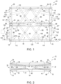
- Collapsible guardrails 10 may be described as having a deployed configuration 54, in which the lower-left-side-leg upper-end region 34 and the upper-left-side-leg lower-end region 40 are adjacent the mid-rail left-end region 20, and in which the lower-right-side-leg upper-end region 46 and the upper-right-side-leg lower-end region 52 are adjacent the mid-rail right-end region 22, as schematically represented in Fig. 1 .
- Collapsible guardrails 10 also may be described as having a collapsed configuration 56, in which the lower-left-side-leg upper-end region 34 and the upper-left-side-leg lower-end region 40 are spaced-away from the mid-rail left-end region 20 toward the mid-rail right-end region 22, and in which the lower-right-side-leg upper-end region 46 and the upper-right-side-leg lower-end region 52 are spaced-away from the mid-rail right-end region 22 toward the mid-rail left-end region 20, as schematically represented in Fig. 2 . Accordingly, collapsible guardrails 10 may be selectively deployed to the deployed configuration 54, such as when collapsible guardrails 10 are needed to restrict personnel access to an adjacent region.
- a collapsible guardrail 10 may be associated with a structure that is positioned above a ground surface, such a lift that is deployed to a lifted configuration.
- collapsible guardrails 10 may be selectively collapsed, or retracted, to the collapsed configuration 56, such as when collapsible guardrails 10 are not needed to restrict personnel access to an adjacent region, for example, when an associated structure, such as a lift, is positioned near or at a ground surface.
- the mid rail 18 defines a mid-rail lower-left track 58, a mid-rail upper-left track 60, a mid-rail lower-right track 62, and a mid-rail upper-right track 64.
- the tracks may take any suitable configuration, such that the respective identified structures are configured to translate along the tracks.
- Various structures may be utilized, including rollers or wheels that are configured to roll along the tracks, pinions (i.e., circular gears) that are meshed with racks (i.e., linear gears) and configured to rotate and translate along the racks, or pins or axles that are configured to slide along the tracks.
- the tracks additionally or alternatively may be, or may be described as, channels, slots, guides, or rails.
- Examples that include rollers or wheels that are configured to roll along the tracks and examples that include pins or axles that slide along the tracks may transition more quickly and/or easily between the deployed configuration 54 and the collapsed configuration 56 than examples that include rack and pinion or other geared configurations. Moreover, such examples may be less prone to binding-up, becoming skewed, or otherwise jamming as a result of transitioning too quickly between the deployed configuration 54 and the collapsed configuration 56.
- the mid-rail lower-left track 58 extends from the mid-rail left-end region 20 toward the mid-rail right-end region 22.
- the lower-left-side-leg upper-end region 34 is configured to translate along the mid-rail lower-left track 58 when the collapsible guardrail 10 transitions between the deployed configuration 54 ( Fig. 1 ) and the collapsed configuration 56 ( Fig. 2 ).
- the mid-rail upper-left track 60 extends from the mid-rail left-end region 20 toward the mid-rail right-end region 22.
- the upper-left-side-leg lower-end region 40 is configured to translate along the mid-rail upper-left track 60 when the collapsible guardrail 10 transitions between the deployed configuration 54 ( Fig 1 ) and the collapsed configuration 56 ( Fig. 2 ).
- the mid-rail upper-left track 60 is distinct from the mid-rail lower-left track 58, such as schematically represented in Figs. 1 and 2 ; however, in other examples, the mid-rail upper-left track 60 and the mid-rail lower-left track 58 are integral with each other.
- the mid-rail lower-right track 62 extends from the mid-rail right-end region 22 toward the mid-rail left-end region 20.
- the lower-right-side-leg upper-end region 46 is configured to translate along the mid-rail lower-right track 62 when the collapsible guardrail 10 transitions between the deployed configuration 54 ( Fig. 1 ) and the collapsed configuration 56 ( Fig. 2 ).
- the mid-rail lower-right track 62 is distinct from the mid-rail lower-left track 58; however, in other examples, the mid-rail lower-right track 62 and the mid-rail lower-left track 58 are integral with each other.
- the mid-rail upper-right track 64 extends from the mid-rail right-end region 22 toward the mid-rail left-end region 20.
- the upper-right-side-leg lower-end region 52 is configured to translate along the mid-rail upper-right track 64 when the collapsible guardrail 10 transitions between the deployed configuration 54 ( Fig. 1 ) and the collapsed configuration ( Fig. 2 ).
- the mid-rail upper-right track 64 is distinct from the mid-rail lower-right track 62; however, in other examples, the mid-rail upper-right track 64 and the mid-rail lower-right track 62 are integral with each other.
- the mid-rail upper-right track 64 is distinct from the mid-rail upper-left track 60; however, in other examples, the mid-rail upper-right track 64 and the mid-rail upper-left track 60 are integral with each other.
- some examples of collapsible guardrails 10 further comprise a left-leg connecting block 66 and a right-leg connecting block 68.
- the left-leg connecting block 66 operatively couples together the lower-left-side-leg upper-end region 34 and the upper-left-side-leg lower-end region 40
- the right-leg connecting block 68 operatively couples together the lower-right-side-leg upper-end region 46 and the upper-right-side-leg lower-end region 52.
- the connecting blocks additionally or alternatively may be described as or referred to as carriages.
- the mid rail 18 further defines a mid-rail left-central track 70 and a mid-rail right-central track 72.
- the mid-rail left-central track 70 extends from the mid-rail left-end region 20 toward the mid-rail right-end region 22, and the left-leg connecting block 66 is configured to translate along the mid-rail left-central track 70 when the collapsible guardrail 10 transitions between the deployed configuration 54 ( Fig. 1 ) and the collapsed configuration 56 ( Fig. 2 ).
- the mid-rail right-central track 72 extends from the mid-rail right-end region 22 toward the mid-rail left-end region 20, and the right-leg connecting block 68 is configured to translate along the mid-rail right-central track 72 when the collapsible guardrail 10 transitions between the deployed configuration 54 ( Fig. 1 ) and the collapsed configuration 56 ( Fig. 2 ).
- the mid-rail right-central track 72 is distinct from the mid-rail left-central track 70; however, in other examples, the mid-rail right-central track 72 and the mid-rail left-central track 70 are integral with each other.
- the left-leg connecting block 66 is operatively engaged with the mid-rail lower-left track 58, the mid-rail upper-left track 60, and the mid-rail left-central track 70 in a left-side triangular pattern 74
- the right-leg connecting block 68 is operatively engaged with the mid-rail lower-right track 62, the mid-rail upper-right track 64, and the mid-rail right-central track 72 in a right-side triangular pattern 76.
- Such spatial configurations facilitate the smooth translation of the connecting blocks along the mid rail 18 without twisting, rotating, or pivoting relative to the mid rail 18, and thus avoiding the connecting blocks from binding-up with the mid rail 18.
- the mid rail 18 comprises a front panel 18' and a rear panel 18" spaced-apart from the front panel 18'.
- the corresponding tracks 58, 60, 62, 64, 70, and 72 therefore have corresponding front and rear sections.
- corresponding loads are separated into two components-one along the front panel 18' and one along the rear panel 18".
- the mid rail 18 further comprises end caps 18′′′ that operatively coupled together the front panel 18' and the rear panel 18".
- the left-leg connecting block 66 and the right-leg connecting block 68 are positioned and configured to slide between the front panel 18' and the rear panel 18".
- the lower-left-side-leg upper-end region 34 is laterally left of the lower-left-side-leg lower-end region 32
- the upper-left-side-leg lower-end region 40 is laterally left of the upper-left-side-leg upper-end region 38
- the lower-right-side-leg upper-end region 46 is laterally right of the lower-right-side-leg lower-end region 44
- the upper-right-side-leg lower-end region 52 is laterally right of the upper-right-side-leg upper-end region 50.
- the legs may be described as being over-center.
- the weight of the top rail 24 and the weight of the mid rail 18 will urge the lower-left-side-leg upper-end region 34 and the upper-left-side-leg lower-end region 40 to the left and against the terminuses of the mid-rail lower-left track 58 and the mid-rail upper-left track 60.
- the weight of the top rail 24 and the weight of the mid rail 18 will urge the lower-right-side-leg upper-end region 46 and the upper-right-side-leg lower-end region 52 to the right and against the terminuses of the mid-rail lower-right track 62 and the mid-rail upper-right track 64.
- the weight of the top rail 24 and the weight of the mid rail 18 will restrict unintentional transition from the deployed configuration ( Fig. 1 ) to the collapsed configuration ( Fig. 2 ).
- collapsible guardrails 10 at least one of the lower-left-side-leg upper-end region 34 and the upper-left-side-leg lower-end region 40 is biased toward the mid-rail left-end region 20, and at least one of the lower-right-side-leg upper-end region 46 and the upper-right-side-leg lower-end region 52 is biased toward the mid-rail right-end region 22.
- the collapsible guardrails 10 are biased toward the deployed configuration 54 ( Fig. 1 ), thereby restricting the inadvertent transition of the collapsible guardrails 10 toward the collapsed configuration 56.
- collapsible guardrails 10 further comprise a left-side spring 78 and a right-side spring 80.
- the springs may be or comprise coil springs, torsion springs, pneumatic cylinders, or hydraulic cylinders.
- the left-side spring 78 is operatively coupled between the base 12 and the lower left-side leg 30 and is configured to bias the lower-left-side-leg mid-rail left-end region 20 or, as schematically illustrated in Fig. 1 , between the top rail 24 and the upper left-side leg 36 and is configured to bias the upper-left-side-leg lower-end region 40 toward the mid-rail left-end region 20.
- the right-side spring 80 is operatively coupled between the base 12 and the lower right-side leg 42 and is configured to bias the lower-right-side-leg upper-end region 46 toward the mid-rail right-end region 22 or, as schematically illustrated in Fig. 1 , between the top rail 24 and the upper right-side leg 48 and is configured to bias the upper-right-side-leg lower-end region 52 toward the mid-rail right-end region 22.
- some collapsible guardrails 10 further comprise one or more motive sources 82 that are configured to selectively translate the lower-left-side-leg upper-end region 34 and the upper-left-side-leg lower-end region 40 toward the mid-rail left-end region 20, and the lower-right-side-leg upper-end region 46 and the upper-right-side-leg lower-end region 52 toward the mid-rail right-end region 22.
- the motive source(s) 82 may directly move the upper legs or the lower legs and indirectly move the lower legs or the upper legs, respectively, or the motive source(s) 82 may directly move the left legs or the right legs and indirectly move the right legs or the left legs, respectively.
- the motive source(s) 82 may comprise any suitable structures and mechanisms, such as motors, gears, chains, cogs, pneumatic mechanisms (e.g., pneumatic cylinders), and/or hydraulic mechanisms (e.g. hydraulic cylinders).
- the motive source 82 is a single motive source 82; however, in other examples and as schematically represented in Fig. 1 , the motive sources 82 comprise a left-side motive source 84 and a right-side motive source 86.
- the left-side motive source 84 is configured to selectively translate the lower-left-side-leg upper-end region 34 and the upper-left-side-leg lower-end region 40 toward the mid-rail left-end region 20, and the right-side motive source 86 is configured to selectively translate the lower-right-side-leg upper-end region 46 and the upper-right-side-leg lower-end region 52 toward the mid-rail right-end region 22.
- the motive source(s) 82 do not include worm gears, lead screws, feed screws, ball screws, threaded nuts, and the like, which otherwise may result in slow operation of a collapsible guardrail 10.
- collapsible guardrails 10 further comprise a controller 88 that is operatively coupled to the motive source(s) 82 and that is configured to operate the motive source(s) 82 responsive to a user input, such as via actuation of a button, a lever, a dial, a keystroke, a touch screen, or other mechanism. Accordingly, a user may selectively deploy a collapsible guardrail 10 to the deployed configuration 54 ( Fig. 1 ) and selectively collapse a collapsible guardrail 10 to the collapsed configuration 56 ( Fig. 2 ).
- a controller 88 that is operatively coupled to the motive source(s) 82 and that is configured to operate the motive source(s) 82 responsive to a user input, such as via actuation of a button, a lever, a dial, a keystroke, a touch screen, or other mechanism.
- a user may selectively deploy a collapsible guardrail 10 to the deployed configuration 54 ( Fig. 1 ) and selectively
- the controller 88 and the motive sources 82 are schematically represented with lightning bolts, schematically representing communication between the controller 88 and the motive source(s) 82. Such communication may be wired or wireless.
- a controller 88 may be any suitable device or devices that are configured to perform the functions of the controller 88 discussed herein.
- the controller 88 may comprise one or more of an electronic controller, a dedicated controller, a special-purpose controller, a personal computer, a special-purpose computer, a display device, a logic device, a memory device, and/or a memory device having computer readable media suitable for storing computer-executable instructions for performing the stated function of the controller 88.
- collapsible guardrails 10 may be described as having a height 126 when in the deployed configuration 54, and each of the lower left-side leg 30, the upper left-side leg 36, the lower right-side leg 42, and the upper right-side leg 48 may be described as having a width 128.
- the width 128 of the legs may be at least 5%, at least 10%, at least 15%, 5-20%, or 10-20% of the height 126.
- selection of a greater width 128 will facilitate greater stability of a collapsible guardrail 10 when a force is applied, for example, to the top rail 24.
- tensile stresses will be concentrated on one of the front or rear edges of the legs, while compressive stresses will be concentrated on the other of the front or rear edges of the legs, when a forward or rearward force is applied to the top rail 24.
- each of the lower left-side leg 30, the upper left-side leg 36, the lower right-side leg 42, and the upper right-side leg 48 comprises a web 130 and at least one flange 132, such as two flanges 132.
- the web 130 extends in the forward and rearward direction, while the flange(s) extend orthogonal to the web 130.
- each of the lower left-side leg 30, the upper left-side leg 36, the lower right-side leg 42, and the upper right-side leg 48 may comprise a C-channel 134, with the flanges 132 positioned on the front and rear edges of the legs.
- the flanges 132 bear the bulk of the compressive and tensile stresses when a moment is applied to the collapsible guardrail 10, such as via a forward or rearward force applied to the top rail 24, resulting in a very sturdy collapsible guardrail 10.
- the compressive and tensile stresses will pass from the flanges 132 through the front panel 18' and the rear panel 18", such as via the associated pins, axles, or other structures, including the optional connecting blocks 66, 68, that operatively couple the legs to the mid rail 18.
- collapsible guardrails 10 further comprise a lattice structure 90 that is operatively coupled between the base 12 and the top rail 24 and that is configured to operatively support the top rail 24 relative to the base 12. That is, the lattice structure 90, when present, provides support in addition to the legs between the top rail 24 and the base 12. In some such examples, the lattice structure 90 also is operatively coupled to the mid rail 18 and is configured to support the mid rail 18 relative to the top rail 24 and the base 12.
- the lattice structure 90 comprises a lower-left lattice member 92, an upper-left lattice member 94, a lower-right lattice member 96, and an upper-right lattice member 98.
- the lattice members additionally or alternatively may be described as arms, beans, elongate members, bars, links, or linkages.
- the lower-left lattice member 92 is pivotally coupled to the base 12.
- the upper-left lattice member 94 is pivotally coupled to the lower-left lattice member 92 and also is pivotally coupled to the top rail 24.
- the lower-right lattice member 96 is pivotally coupled to the base 12.
- the upper-right lattice member 98 is pivotally coupled to the lower-right lattice member 96 and also is pivotally coupled to the top rail 24.
- the lower-left lattice member 92 and the lower-right lattice member 96 share a pivot axis along the base 12.
- the upper-left lattice member 94 and the upper-right lattice member 98 share a pivot axis along the top rail 24. Accordingly, in such examples, and as schematically illustrated in Fig. 1 , the lower-left lattice member 92, the upper-left lattice member 94, the lower-right lattice member 96 pivotally coupled to the base 12, and the upper-right lattice member 98 define a parallelogram.
- the lattice structure 90 further comprises a first angled member 100 and a second angled member 106.
- the first angled member 100 comprises a first-angled-member lower-end region 102 and a first-angled-member upper-end region 104 that is opposite the first-angled-member lower-end region 102.
- the first-angled-member lower-end region 102 is pivotally and translationally coupled to the base 12, and the first-angled-member upper-end region 104 is pivotally and translationally coupled to the top rail 24.
- the second angled member 106 comprises a second-angled-member lower-end region 108 and a second-angled-member upper-end region 110 that is opposite the second-angled-member lower-end region 108.
- the second-angled-member lower-end region 108 is pivotally and translationally coupled to the base 12, and the second-angled-member upper-end region 110 is pivotally and translationally coupled to the top rail 24.
- the base 12 defines a base left-side track 112 and a base right-side track 114
- the top rail 24 defines a top-rail left-side track 116 and a top-rail right-side track 118.
- the base left-side track 112 extends from the base left-end region 14 toward the base right-end region 16, and the first-angled-member lower-end region 102 is configured to translate along the base left-side track 112 when the collapsible guardrail 10 transitions between the deployed configuration 54 and the collapsed configuration 56.
- the base right-side track 114 extends from the base right-end region 16 toward the base left-end region 14, and the second-angled-member lower-end region 108 is configured to translate along the base right-side track 114 when the collapsible guardrail 10 transitions between the deployed configuration 54 and the collapsed configuration 56.
- the top-rail left-side track 116 extends from the top-rail left-end region 26 toward the top-rail right-end region 28, and the second-angled-member upper-end region 110 is configured to translate along the top-rail left-side track 116 when the collapsible guardrail 10 transitions between the deployed configuration 54 and the collapsed configuration 56.
- the top-rail right-side track 119 extends from the top-rail right-end region 28 toward the top-rail left-end region 26, and the first-angled-member upper-end region 104 is configured to translate along the top-rail right-side track 118 when the collapsible guardrail 10 transitions between the deployed configuration 54 and the collapsed configuration 56.
- the first angled member 100 is pivotally coupled to the second angled member 106.
- the first angled member 100 and the second angled member 106 are pivotally coupled to the mid rail 18.
- the first angled member 100 and the second angled member 106 share an axis at the mid rail 18.
- the first angled member 100 and the second angled member 106 may be described as defining an X shape.
- the lattice structure 90 comprises all six of the lower-left lattice member 92, the upper-left lattice member 94, the lower-right lattice member 96, the upper-right lattice member 98, the first angled member 100, and the second angled member 106
- the first angled member 100 may be pivotally coupled to both the lower-left lattice member 92 and the upper-right lattice member 98
- the second angled member 106 may be pivotally coupled to both the upper-left lattice member 94 and to the lower-right lattice member 96, as schematically represented in Fig. 1 .
- the lattice structure 90 maintains a parallel relationship between the base 12, the mid rail 18, and the top rail 24 and restricts them from binding-up or otherwise inhibiting the smooth transition of a such a collapsible guardrail 10 between the deployed configuration 54 and the collapsed configuration.
- some collapsible guardrails 10 further comprise at least one screen 120 that is operatively coupled between the base 12 and the top rail 24 and that is configured to restrict access to at least the mid rail 18.
- the screen(s) are operatively coupled to the mid rail 18.
- a screen 120 may be present to restrict personnel from inadvertently entering the space between the base 12 and the top rail 24, such as according to the United States Occupational Safety and Health Administration (OSHA) standards, or other similar governmental or safety standards around the world.
- the screen(s) 120 may be coupled to the front and/or to the back of a collapsible guardrail 10.
- the screen(s) further restrict access to the lattice structure 90, when present, while in other examples, the lattice structure 90, when present, is positioned on the outside of a screen 120.
- the screen(s) 120 are configured to restrict access to the left-side spring 78 and to the right-side spring 80, when present.
- the screen(s) 120 are configured to restrict access to the motive source(s) 82.
- Screens 120 additionally or alternatively may be described as curtains and may be corrugated and/or may define an accordion, or folded, configuration.
- Collapsible guardrails 10 may be configured for installation in a variety of environments. As schematically represented on the right side of Fig. 1 , the base 12 may be configured to be mounted to an upper surface 122 of a structure 124. Additionally or alternatively, as schematically represented on the left side of Fig. 1 , the base 12 may be configured to be below an upper surface 122 of a structure 124.
- Figs. 5-9 illustrative non-exclusive examples of collapsible guardrails 10 in the form of a collapsible guardrail 200 ( Figs. 5-8 ) and collapsible guardrail 300 ( Fig. 9 ) are illustrated.
- the reference numerals from the schematic illustrations of Figs. 1-4 are used to designate corresponding parts of the collapsible guardrails 200, 300; however, the examples of Figs. 5-9 are non-exclusive and do not limit collapsible guardrails 10 to the illustrated embodiment of the collapsible guardrails 200, 300.
- collapsible guardrails 10 are not limited to the specific embodiments of the illustrated collapsible guardrails 200, 300, and collapsible guardrails 10 may incorporate any number of the various aspects, configurations, characteristics, properties, etc. of collapsible guardrails 10 that are illustrated in and discussed with reference to the schematic representations of Figs. 1-4 and/or the embodiments of Figs. 5-9 , as well as variations thereof, without requiring the inclusion of all such aspects, configurations, characteristics, properties, etc.
- the collapsible guardrail 200 is an example of a collapsible guardrail 10 that comprises tracks 58, 60, 62, 64, 70, 72, 112, 114, 116, 118, connecting blocks 66, 68, springs 78, 80, motive sources 84, 86, two lattice structures 90, each comprising members 92, 94, 96, 98, 100, 106, and four screens 120.
- the left-side motive source 84 comprises a left-side pneumatic cylinder 202 operatively coupled between the base 12 and the lower left-side leg 30, and the right-side motive source 86 similarly comprises a right-side pneumatic cylinder 204 operatively coupled between the base 12 and the lower right-side leg 42.
- the legs 30, 36, 42, 48 each comprise a C-channel 134.
- the collapsible guardrail 300 illustrated in Fig. 9 is constructed similarly to the collapsible guardrail 200 of Figs. 5-9 , except that the left-side motive source 84 comprises a left-side pneumatic motor 302 supported by the base 12 and operatively coupled to a left-leg axle 304 of the lower left-side leg 30, and the right-side motive source 86 comprises a right-side pneumatic motor 306 supported by the base 12 and operatively coupled to a right-leg axle 308 of the lower right-side leg 42.
- the collapsible guardrail 300 further comprises a chain and gear train 310 operatively coupled between the left-leg axle 304 and the right-leg axle 308 to ensure that the lower left-side leg 30 and the lower right-side leg 42 are synchronized when the collapsible guardrail 300 transitions between the deployed configuration 54 and the collapsed configuration 56.
- the terms “adapted” and “configured” mean that the element, component, or other subject matter is designed and/or intended to perform a given function. Thus, the use of the terms “adapted” and “configured” should not be construed to mean that a given element, component, or other subject matter is simply “capable of” performing a given function but that the element, component, and/or other subject matter is specifically selected, created, implemented, utilized, programmed, and/or designed for the purpose of performing the function. It is also within the scope of the present disclosure that elements, components, and/or other recited subject matter that is recited as being adapted to perform a particular function may additionally or alternatively be described as being configured to perform that function, and vice versa. Similarly, subject matter that is recited as being configured to perform a particular function may additionally or alternatively be described as being operative to perform that function.
Landscapes
- Engineering & Computer Science (AREA)
- Architecture (AREA)
- Civil Engineering (AREA)
- Structural Engineering (AREA)
- Mechanical Engineering (AREA)
- Refuge Islands, Traffic Blockers, Or Guard Fence (AREA)
- Seats For Vehicles (AREA)
Abstract
Collapsible guardrails comprise a base, a mid rail, a top rail, a lower left-side leg, an upper left-side leg, a lower right-side leg, and an upper right-side leg. Collapsible guardrails have a deployed configuration and a collapsed configuration.
Description
- The present disclosure relates to collapsible guardrails.
- In the manufacturing industry, fall protection is paramount when personnel are working above ground level. Guardrails are used on lifts and other high platforms to prevent falls. When not above ground level, however, guardrails may be obtrusive and restrict access to necessary manufacturing components, supplies, tools, and the like. Existing collapsible guardrails are expensive, are slow to deploy, and require regular maintenance.
- Collapsible guardrails according to the present disclosure comprise a base, a mid rail, a top rail, a lower left-side leg, an upper left-side leg, a lower right-side leg, and an upper right-side leg. Collapsible guardrails have a deployed configuration and a collapsed configuration.
-
-
Fig. 1 is schematic front view representing collapsible guardrails according to the present disclosure in a deployed configuration. -
Fig. 2 is a schematic front view representing collapsible guardrails according to the present disclosure in a collapsed configuration. -
Fig. 3 is a schematic side view representing collapsible guardrails according to the present disclosure in a deployed configuration. -
Fig. 4 is a schematic side view representing collapsible guardrails according to the present disclosure in a collapsed configuration. -
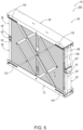
Fig. 5 is an isometric view of an example collapsible guardrail according to the present disclosure, shown in its deployed configuration. -
Fig. 6 is a side view of the collapsible guardrail ofFig. 5 . -
Fig. 7 is a front view of the collapsible guardrail ofFig. 5 with the screens removed for clarity. -
Fig. 8 is a partial perspective view of the collapsible guardrail ofFig. 5 , showing the motive source. -
Fig. 9 is a partial perspective view of another collapsible guardrail, shown in its deployed configuration and showing the motive source. -
Collapsible guardrails 10 are disclosed herein and schematically represented inFigs. 1-4 . Generally, inFigs. 1-4 , elements that are likely to be included in a given example are illustrated in solid lines, while elements that are optional to or that correspond to a given example are illustrated in dashed lines. However, elements that are illustrated in solid lines are not essential to all examples of the present disclosure, and an element shown in solid lines may be omitted from a particular example without departing from the scope of the present disclosure. - As schematically represented in
Figs. 1-4 ,collapsible guardrails 10 comprise at least abase 12, amid rail 18, atop rail 24, and four legs, namely, a lower left-side leg 30, an upper left-side leg 36, a lower right-side leg 42, and an upper right-side leg 48. - As indicated in
Fig. 1 , thebase 12 comprises a base left-end region 14 and a base right-end region 16 that is opposite the base left-end region 14. In some examples, thebase 12 additionally or alternatively may be described as a rail, a beam, or a support. WhileFig. 1 schematically illustrates thebase 12 extending continuously from the base left-end region 14 to the base right-end region 16, such a configuration is not required in all examples, and in some examples, the base left-end region 14 may be a distinct structure from the base right-end region 16. As used herein "end regions" are not limited to the terminus of a structure, but rather includes theterminal 20% of a length of the structure. - As schematically indicated in
Fig. 1 , themid rail 18 is positioned above thebase 12, and in some examples may be parallel to thebase 12. Herein, positional terms, such as "above," "below," left," "right," and so forth refer tocollapsible guardrails 10 when operatively positioned for use and as presented in the figures. As indicated inFig. 1 , themid rail 18 comprises a mid-rail left-end region 20 and a mid-rail right-end region 22 that is opposite the mid-rail left-end region 20. The mid-rail left-end region 20 is positioned above the base left-end region 14, and the mid-rail right-end region 22 is positioned above the base right-end region 16. Herein, a "rail" additionally or alternatively may be described as a beam or an elongate support. - As schematically illustrated in
Fig. 1 , thetop rail 24 is positioned above and parallel to themid rail 18 and comprises a top-rail left-end region 26 and a top-rail right-end region 28 that is opposite the top-rail left-end region 26. The top-rail left-end region 26 is positioned above the mid-rail left-end region 20, and the top-rail right-end region 28 is positioned above the mid-rail right-end region 22. - The legs additionally or alternatively may be described as arms, elongate supports, or linkages, and may be described in terms of their respective end regions and their relationships to the
base 12, themid rail 18, and thetop rail 24. In particular, and as schematically indicated inFig. 1 , the lower left-side leg 30 comprises a lower-left-side-leg lower-end region 32 and a lower-left-side-leg upper-end region 34 that is opposite the lower-left-side-leg lower-end region 32. The lower-left-side-leg lower-end region 32 is pivotally coupled to the base left-end region 14, and the lower-left-side-leg upper-end region 34 is pivotally and translationally coupled to themid rail 18. The upper left-side leg 36 is positioned above the lower left-side leg 30 and comprises an upper-left-side-leg upper-end region 38 and an upper-left-side-leg lower-end region 40 that is opposite the upper-left-side-leg upper-end region 38. The upper-left-side-leg upper-end region 38 is pivotally coupled to the top-rail left-end region 26, and the upper-left-side-leg lower-end region 40 is pivotally and translationally coupled to themid rail 18. - Similarly, the lower right-
side leg 42 comprises a lower-right-side-leg lower-end region 44 and a lower-right-side-leg upper-end region 46 that is opposite the lower-right-side-leg lower-end region 44. The lower-right-side-leg lower-end region 44 is pivotally coupled to the base right-end region 16, and the lower-right-side-leg upper-end region 46 is pivotally and translationally coupled to themid rail 18. The upper right-side leg 48 is positioned above the lower right-side leg 42 and comprises an upper-right-side-leg upper-end region 50 and an upper-right-side-leg lower-end region 52 that is opposite the upper-right-side-leg upper-end region 50. The upper-right-side-leg upper-end region 50 is pivotally coupled to the top-rail right-end region 28, and the upper-right-side-leg lower-end region 52 is pivotally and translationally coupled to themid rail 18. -
Collapsible guardrails 10 may be described as having a deployedconfiguration 54, in which the lower-left-side-leg upper-end region 34 and the upper-left-side-leg lower-end region 40 are adjacent the mid-rail left-end region 20, and in which the lower-right-side-leg upper-end region 46 and the upper-right-side-leg lower-end region 52 are adjacent the mid-rail right-end region 22, as schematically represented inFig. 1 .Collapsible guardrails 10 also may be described as having a collapsedconfiguration 56, in which the lower-left-side-leg upper-end region 34 and the upper-left-side-leg lower-end region 40 are spaced-away from the mid-rail left-end region 20 toward the mid-rail right-end region 22, and in which the lower-right-side-leg upper-end region 46 and the upper-right-side-leg lower-end region 52 are spaced-away from the mid-rail right-end region 22 toward the mid-rail left-end region 20, as schematically represented inFig. 2 . Accordingly,collapsible guardrails 10 may be selectively deployed to the deployedconfiguration 54, such as whencollapsible guardrails 10 are needed to restrict personnel access to an adjacent region. For example, acollapsible guardrail 10 may be associated with a structure that is positioned above a ground surface, such a lift that is deployed to a lifted configuration. Conversely,collapsible guardrails 10 may be selectively collapsed, or retracted, to the collapsedconfiguration 56, such as whencollapsible guardrails 10 are not needed to restrict personnel access to an adjacent region, for example, when an associated structure, such as a lift, is positioned near or at a ground surface. - With reference to
Figs. 1 and 2 , in some examples, themid rail 18 defines a mid-rail lower-left track 58, a mid-rail upper-left track 60, a mid-rail lower-right track 62, and a mid-rail upper-right track 64. The tracks may take any suitable configuration, such that the respective identified structures are configured to translate along the tracks. Various structures may be utilized, including rollers or wheels that are configured to roll along the tracks, pinions (i.e., circular gears) that are meshed with racks (i.e., linear gears) and configured to rotate and translate along the racks, or pins or axles that are configured to slide along the tracks. The tracks additionally or alternatively may be, or may be described as, channels, slots, guides, or rails. Examples that include rollers or wheels that are configured to roll along the tracks and examples that include pins or axles that slide along the tracks may transition more quickly and/or easily between the deployedconfiguration 54 and the collapsedconfiguration 56 than examples that include rack and pinion or other geared configurations. Moreover, such examples may be less prone to binding-up, becoming skewed, or otherwise jamming as a result of transitioning too quickly between the deployedconfiguration 54 and the collapsedconfiguration 56. - The mid-rail lower-
left track 58 extends from the mid-rail left-end region 20 toward the mid-rail right-end region 22. The lower-left-side-leg upper-end region 34 is configured to translate along the mid-rail lower-left track 58 when thecollapsible guardrail 10 transitions between the deployed configuration 54 (Fig. 1 ) and the collapsed configuration 56 (Fig. 2 ). - The mid-rail upper-
left track 60 extends from the mid-rail left-end region 20 toward the mid-rail right-end region 22. The upper-left-side-leg lower-end region 40 is configured to translate along the mid-rail upper-left track 60 when thecollapsible guardrail 10 transitions between the deployed configuration 54 (Fig 1 ) and the collapsed configuration 56 (Fig. 2 ). In some examples, the mid-rail upper-left track 60 is distinct from the mid-rail lower-left track 58, such as schematically represented inFigs. 1 and 2 ; however, in other examples, the mid-rail upper-left track 60 and the mid-rail lower-left track 58 are integral with each other. - The mid-rail lower-
right track 62 extends from the mid-rail right-end region 22 toward the mid-rail left-end region 20. The lower-right-side-leg upper-end region 46 is configured to translate along the mid-rail lower-right track 62 when thecollapsible guardrail 10 transitions between the deployed configuration 54 (Fig. 1 ) and the collapsed configuration 56 (Fig. 2 ). In some examples, as schematically represented inFigs. 1 and 2 , the mid-rail lower-right track 62 is distinct from the mid-rail lower-left track 58; however, in other examples, the mid-rail lower-right track 62 and the mid-rail lower-left track 58 are integral with each other. - The mid-rail upper-
right track 64 extends from the mid-rail right-end region 22 toward the mid-rail left-end region 20. The upper-right-side-leg lower-end region 52 is configured to translate along the mid-rail upper-right track 64 when thecollapsible guardrail 10 transitions between the deployed configuration 54 (Fig. 1 ) and the collapsed configuration (Fig. 2 ). In some examples, as schematically represented inFigs. 1 and 2 , the mid-rail upper-right track 64 is distinct from the mid-rail lower-right track 62; however, in other examples, the mid-rail upper-right track 64 and the mid-rail lower-right track 62 are integral with each other. In some examples, as schematically represented inFigs. 1 and 2 , the mid-rail upper-right track 64 is distinct from the mid-rail upper-lefttrack 60; however, in other examples, the mid-rail upper-right track 64 and the mid-rail upper-lefttrack 60 are integral with each other. - As schematically illustrated in
Fig. 1 , some examples ofcollapsible guardrails 10 further comprise a left-leg connecting block 66 and a right-leg connecting block 68. The left-leg connecting block 66 operatively couples together the lower-left-side-leg upper-end region 34 and the upper-left-side-leg lower-end region 40, and the right-leg connecting block 68 operatively couples together the lower-right-side-leg upper-end region 46 and the upper-right-side-leg lower-end region 52. The connecting blocks additionally or alternatively may be described as or referred to as carriages. - In some examples, as schematically illustrated in
Fig. 1 , themid rail 18 further defines a mid-rail left-central track 70 and a mid-rail right-central track 72. The mid-rail left-central track 70 extends from the mid-rail left-end region 20 toward the mid-rail right-end region 22, and the left-leg connecting block 66 is configured to translate along the mid-rail left-central track 70 when thecollapsible guardrail 10 transitions between the deployed configuration 54 (Fig. 1 ) and the collapsed configuration 56 (Fig. 2 ). The mid-rail right-central track 72 extends from the mid-rail right-end region 22 toward the mid-rail left-end region 20, and the right-leg connecting block 68 is configured to translate along the mid-rail right-central track 72 when thecollapsible guardrail 10 transitions between the deployed configuration 54 (Fig. 1 ) and the collapsed configuration 56 (Fig. 2 ). In some examples, as schematically represented inFig. 1 , the mid-rail right-central track 72 is distinct from the mid-rail left-central track 70; however, in other examples, the mid-rail right-central track 72 and the mid-rail left-central track 70 are integral with each other. - In some examples, as schematically represented in
Fig. 1 , the left-leg connecting block 66 is operatively engaged with the mid-rail lower-lefttrack 58, the mid-rail upper-lefttrack 60, and the mid-rail left-central track 70 in a left-side triangular pattern 74, and the right-leg connecting block 68 is operatively engaged with the mid-rail lower-right track 62, the mid-rail upper-right track 64, and the mid-rail right-central track 72 in a right-sidetriangular pattern 76. Such spatial configurations facilitate the smooth translation of the connecting blocks along themid rail 18 without twisting, rotating, or pivoting relative to themid rail 18, and thus avoiding the connecting blocks from binding-up with themid rail 18. - In some examples, the
mid rail 18 comprises a front panel 18' and arear panel 18" spaced-apart from the front panel 18'. In such examples, the correspondingtracks rear panel 18". Such a configuration results in a more stablecollapsible guardrail 10 than if the corresponding loads along themid rail 18 were singularly positioned along a mid-line of thecollapsible guardrail 10. In some examples, themid rail 18 further comprisesend caps 18‴ that operatively coupled together the front panel 18' and therear panel 18". In some examples, the left-leg connecting block 66 and the right-leg connecting block 68 are positioned and configured to slide between the front panel 18' and therear panel 18". - In some examples of
collapsible guardrails 10, when thecollapsible guardrail 10 is in the deployed configuration 54 (Fig. 1 ), the lower-left-side-leg upper-end region 34 is laterally left of the lower-left-side-leg lower-end region 32, the upper-left-side-leg lower-end region 40 is laterally left of the upper-left-side-leg upper-end region 38, the lower-right-side-leg upper-end region 46 is laterally right of the lower-right-side-leg lower-end region 44, and the upper-right-side-leg lower-end region 52 is laterally right of the upper-right-side-leg upper-end region 50. In other words, in the deployed configuration 54 (Fig. 1 ), the legs may be described as being over-center. That is, the weight of thetop rail 24 and the weight of themid rail 18 will urge the lower-left-side-leg upper-end region 34 and the upper-left-side-leg lower-end region 40 to the left and against the terminuses of the mid-rail lower-lefttrack 58 and the mid-rail upper-lefttrack 60. Similarly, the weight of thetop rail 24 and the weight of themid rail 18 will urge the lower-right-side-leg upper-end region 46 and the upper-right-side-leg lower-end region 52 to the right and against the terminuses of the mid-rail lower-right track 62 and the mid-rail upper-right track 64. In such a configuration, the weight of thetop rail 24 and the weight of themid rail 18 will restrict unintentional transition from the deployed configuration (Fig. 1 ) to the collapsed configuration (Fig. 2 ). - In some examples of
collapsible guardrails 10, at least one of the lower-left-side-leg upper-end region 34 and the upper-left-side-leg lower-end region 40 is biased toward the mid-rail left-end region 20, and at least one of the lower-right-side-leg upper-end region 46 and the upper-right-side-leg lower-end region 52 is biased toward the mid-rail right-end region 22. In examples where the left legs are coupled together via a left-leg connecting block 66 and the right legs are coupled together via a right-leg connecting block 68, thecollapsible guardrails 10 are biased toward the deployed configuration 54 (Fig. 1 ), thereby restricting the inadvertent transition of thecollapsible guardrails 10 toward thecollapsed configuration 56. - In some examples,
collapsible guardrails 10 further comprise a left-side spring 78 and a right-side spring 80. As examples, the springs may be or comprise coil springs, torsion springs, pneumatic cylinders, or hydraulic cylinders. The left-side spring 78 is operatively coupled between the base 12 and the lower left-side leg 30 and is configured to bias the lower-left-side-leg mid-rail left-end region 20 or, as schematically illustrated inFig. 1 , between thetop rail 24 and the upper left-side leg 36 and is configured to bias the upper-left-side-leg lower-end region 40 toward the mid-rail left-end region 20. The right-side spring 80 is operatively coupled between the base 12 and the lower right-side leg 42 and is configured to bias the lower-right-side-leg upper-end region 46 toward the mid-rail right-end region 22 or, as schematically illustrated inFig. 1 , between thetop rail 24 and the upper right-side leg 48 and is configured to bias the upper-right-side-leg lower-end region 52 toward the mid-rail right-end region 22. - With continued reference to
Fig. 1 , as schematically represented, somecollapsible guardrails 10 further comprise one ormore motive sources 82 that are configured to selectively translate the lower-left-side-leg upper-end region 34 and the upper-left-side-leg lower-end region 40 toward the mid-rail left-end region 20, and the lower-right-side-leg upper-end region 46 and the upper-right-side-leg lower-end region 52 toward the mid-rail right-end region 22. In examples where the left legs are coupled together via a left-leg connecting block 66 and the right legs are coupled together via a right-leg connecting block 68, the motive source(s) 82 may directly move the upper legs or the lower legs and indirectly move the lower legs or the upper legs, respectively, or the motive source(s) 82 may directly move the left legs or the right legs and indirectly move the right legs or the left legs, respectively. The motive source(s) 82 may comprise any suitable structures and mechanisms, such as motors, gears, chains, cogs, pneumatic mechanisms (e.g., pneumatic cylinders), and/or hydraulic mechanisms (e.g. hydraulic cylinders). - In some examples, the
motive source 82 is asingle motive source 82; however, in other examples and as schematically represented inFig. 1 , the motive sources 82 comprise a left-side motive source 84 and a right-side motive source 86. The left-side motive source 84 is configured to selectively translate the lower-left-side-leg upper-end region 34 and the upper-left-side-leg lower-end region 40 toward the mid-rail left-end region 20, and the right-side motive source 86 is configured to selectively translate the lower-right-side-leg upper-end region 46 and the upper-right-side-leg lower-end region 52 toward the mid-rail right-end region 22. - In some examples, the motive source(s) 82 do not include worm gears, lead screws, feed screws, ball screws, threaded nuts, and the like, which otherwise may result in slow operation of a
collapsible guardrail 10. - As schematically indicated in
Fig. 1 , in some examples,collapsible guardrails 10 further comprise acontroller 88 that is operatively coupled to the motive source(s) 82 and that is configured to operate the motive source(s) 82 responsive to a user input, such as via actuation of a button, a lever, a dial, a keystroke, a touch screen, or other mechanism. Accordingly, a user may selectively deploy acollapsible guardrail 10 to the deployed configuration 54 (Fig. 1 ) and selectively collapse acollapsible guardrail 10 to the collapsed configuration 56 (Fig. 2 ). InFig. 1 , thecontroller 88 and the motive sources 82 are schematically represented with lightning bolts, schematically representing communication between thecontroller 88 and the motive source(s) 82. Such communication may be wired or wireless. Acontroller 88 may be any suitable device or devices that are configured to perform the functions of thecontroller 88 discussed herein. For example, thecontroller 88 may comprise one or more of an electronic controller, a dedicated controller, a special-purpose controller, a personal computer, a special-purpose computer, a display device, a logic device, a memory device, and/or a memory device having computer readable media suitable for storing computer-executable instructions for performing the stated function of thecontroller 88. - Turning to
Fig. 3 , which schematically illustratescollapsible guardrails 10 in the deployed configuration,collapsible guardrails 10 may be described as having aheight 126 when in the deployedconfiguration 54, and each of the lower left-side leg 30, the upper left-side leg 36, the lower right-side leg 42, and the upper right-side leg 48 may be described as having awidth 128. In various examples, thewidth 128 of the legs may be at least 5%, at least 10%, at least 15%, 5-20%, or 10-20% of theheight 126. In particular, selection of agreater width 128 will facilitate greater stability of acollapsible guardrail 10 when a force is applied, for example, to thetop rail 24. Moreover, tensile stresses will be concentrated on one of the front or rear edges of the legs, while compressive stresses will be concentrated on the other of the front or rear edges of the legs, when a forward or rearward force is applied to thetop rail 24. - In some examples, as schematically indicated in
Figs. 1 and3 , each of the lower left-side leg 30, the upper left-side leg 36, the lower right-side leg 42, and the upper right-side leg 48 comprises aweb 130 and at least oneflange 132, such as twoflanges 132. When present, theweb 130 extends in the forward and rearward direction, while the flange(s) extend orthogonal to theweb 130. As an example, each of the lower left-side leg 30, the upper left-side leg 36, the lower right-side leg 42, and the upper right-side leg 48 may comprise a C-channel 134, with theflanges 132 positioned on the front and rear edges of the legs. As a result, theflanges 132 bear the bulk of the compressive and tensile stresses when a moment is applied to thecollapsible guardrail 10, such as via a forward or rearward force applied to thetop rail 24, resulting in a very sturdycollapsible guardrail 10. In examples ofcollapsible guardrails 10 whosemid rail 18 comprises a front panel 18' and arear panel 18" and whose legs comprise a C-channel 134, the compressive and tensile stresses will pass from theflanges 132 through the front panel 18' and therear panel 18", such as via the associated pins, axles, or other structures, including the optional connectingblocks mid rail 18. - With continued reference to
Fig. 1 , some examples ofcollapsible guardrails 10 further comprise alattice structure 90 that is operatively coupled between the base 12 and thetop rail 24 and that is configured to operatively support thetop rail 24 relative to thebase 12. That is, thelattice structure 90, when present, provides support in addition to the legs between thetop rail 24 and thebase 12. In some such examples, thelattice structure 90 also is operatively coupled to themid rail 18 and is configured to support themid rail 18 relative to thetop rail 24 and thebase 12. - As schematically illustrated in
Fig. 1 , in some examples, thelattice structure 90 comprises a lower-leftlattice member 92, an upper-leftlattice member 94, a lower-right lattice member 96, and an upper-right lattice member 98. The lattice members additionally or alternatively may be described as arms, beans, elongate members, bars, links, or linkages. The lower-leftlattice member 92 is pivotally coupled to thebase 12. The upper-leftlattice member 94 is pivotally coupled to the lower-leftlattice member 92 and also is pivotally coupled to thetop rail 24. The lower-right lattice member 96 is pivotally coupled to thebase 12. The upper-right lattice member 98 is pivotally coupled to the lower-right lattice member 96 and also is pivotally coupled to thetop rail 24. In some examples and as schematically represented inFig. 1 , the lower-leftlattice member 92 and the lower-right lattice member 96 share a pivot axis along thebase 12. Similarly, in some examples, the upper-leftlattice member 94 and the upper-right lattice member 98 share a pivot axis along thetop rail 24. Accordingly, in such examples, and as schematically illustrated inFig. 1 , the lower-leftlattice member 92, the upper-leftlattice member 94, the lower-right lattice member 96 pivotally coupled to thebase 12, and the upper-right lattice member 98 define a parallelogram. - With continued reference to
Fig. 1 , in some examples, thelattice structure 90 further comprises a firstangled member 100 and a secondangled member 106. The firstangled member 100 comprises a first-angled-member lower-end region 102 and a first-angled-member upper-end region 104 that is opposite the first-angled-member lower-end region 102. The first-angled-member lower-end region 102 is pivotally and translationally coupled to thebase 12, and the first-angled-member upper-end region 104 is pivotally and translationally coupled to thetop rail 24. The secondangled member 106 comprises a second-angled-member lower-end region 108 and a second-angled-member upper-end region 110 that is opposite the second-angled-member lower-end region 108. The second-angled-member lower-end region 108 is pivotally and translationally coupled to thebase 12, and the second-angled-member upper-end region 110 is pivotally and translationally coupled to thetop rail 24. As a result, when such acollapsible guardrail 10 transitions between the deployedconfiguration 54 and thecollapsed configuration 56, the end regions of the firstangled member 100 and the secondangled member 106 translate along thebase 12 and thetop rail 24. - In some such examples and as schematically represented in
Fig. 1 , thebase 12 defines a base left-side track 112 and a base right-side track 114, and thetop rail 24 defines a top-rail left-side track 116 and a top-rail right-side track 118. The base left-side track 112 extends from the base left-end region 14 toward the base right-end region 16, and the first-angled-member lower-end region 102 is configured to translate along the base left-side track 112 when thecollapsible guardrail 10 transitions between the deployedconfiguration 54 and thecollapsed configuration 56. The base right-side track 114 extends from the base right-end region 16 toward the base left-end region 14, and the second-angled-member lower-end region 108 is configured to translate along the base right-side track 114 when thecollapsible guardrail 10 transitions between the deployedconfiguration 54 and thecollapsed configuration 56. The top-rail left-side track 116 extends from the top-rail left-end region 26 toward the top-rail right-end region 28, and the second-angled-member upper-end region 110 is configured to translate along the top-rail left-side track 116 when thecollapsible guardrail 10 transitions between the deployedconfiguration 54 and thecollapsed configuration 56. The top-rail right-side track 119 extends from the top-rail right-end region 28 toward the top-rail left-end region 26, and the first-angled-member upper-end region 104 is configured to translate along the top-rail right-side track 118 when thecollapsible guardrail 10 transitions between the deployedconfiguration 54 and thecollapsed configuration 56. - In some examples, as schematically represented in
Fig. 1 , the firstangled member 100 is pivotally coupled to the secondangled member 106. In some examples, the firstangled member 100 and the secondangled member 106 are pivotally coupled to themid rail 18. In some such examples, the firstangled member 100 and the secondangled member 106 share an axis at themid rail 18. In some examples, the firstangled member 100 and the secondangled member 106 may be described as defining an X shape. - In examples in which the
lattice structure 90 comprises all six of the lower-leftlattice member 92, the upper-leftlattice member 94, the lower-right lattice member 96, the upper-right lattice member 98, the firstangled member 100, and the secondangled member 106, the firstangled member 100 may be pivotally coupled to both the lower-leftlattice member 92 and the upper-right lattice member 98, and the secondangled member 106 may be pivotally coupled to both the upper-leftlattice member 94 and to the lower-right lattice member 96, as schematically represented inFig. 1 . As a result, in such examples, thelattice structure 90 maintains a parallel relationship between the base 12, themid rail 18, and thetop rail 24 and restricts them from binding-up or otherwise inhibiting the smooth transition of a such acollapsible guardrail 10 between the deployedconfiguration 54 and the collapsed configuration. - With continued reference to
Fig. 1 and schematically and optionally illustrated in fragment, somecollapsible guardrails 10 further comprise at least onescreen 120 that is operatively coupled between the base 12 and thetop rail 24 and that is configured to restrict access to at least themid rail 18. In some examples, the screen(s) are operatively coupled to themid rail 18. In particular, ascreen 120 may be present to restrict personnel from inadvertently entering the space between the base 12 and thetop rail 24, such as according to the United States Occupational Safety and Health Administration (OSHA) standards, or other similar governmental or safety standards around the world. The screen(s) 120 may be coupled to the front and/or to the back of acollapsible guardrail 10. In some examples, the screen(s) further restrict access to thelattice structure 90, when present, while in other examples, thelattice structure 90, when present, is positioned on the outside of ascreen 120. In some examples, the screen(s) 120 are configured to restrict access to the left-side spring 78 and to the right-side spring 80, when present. In some examples, the screen(s) 120 are configured to restrict access to the motive source(s) 82.Screens 120 additionally or alternatively may be described as curtains and may be corrugated and/or may define an accordion, or folded, configuration. -
Collapsible guardrails 10 may be configured for installation in a variety of environments. As schematically represented on the right side ofFig. 1 , thebase 12 may be configured to be mounted to anupper surface 122 of astructure 124. Additionally or alternatively, as schematically represented on the left side ofFig. 1 , thebase 12 may be configured to be below anupper surface 122 of astructure 124. - Turning now to
Figs. 5-9 , illustrative non-exclusive examples ofcollapsible guardrails 10 in the form of a collapsible guardrail 200 (Figs. 5-8 ) and collapsible guardrail 300 (Fig. 9 ) are illustrated. Where appropriate, the reference numerals from the schematic illustrations ofFigs. 1-4 are used to designate corresponding parts of thecollapsible guardrails Figs. 5-9 are non-exclusive and do not limitcollapsible guardrails 10 to the illustrated embodiment of thecollapsible guardrails collapsible guardrails 10 are not limited to the specific embodiments of the illustratedcollapsible guardrails collapsible guardrails 10 may incorporate any number of the various aspects, configurations, characteristics, properties, etc. ofcollapsible guardrails 10 that are illustrated in and discussed with reference to the schematic representations ofFigs. 1-4 and/or the embodiments ofFigs. 5-9 , as well as variations thereof, without requiring the inclusion of all such aspects, configurations, characteristics, properties, etc. For the purpose of brevity, each previously discussed component, part, portion, aspect, region, etc. or variants thereof may not be discussed, illustrated, and/or labeled again with respect to thecollapsible guardrails collapsible guardrails - As illustrated in
Figs. 5-8 , thecollapsible guardrail 200 is an example of acollapsible guardrail 10 that comprisestracks blocks motive sources lattice structures 90, each comprisingmembers screens 120. The left-side motive source 84 comprises a left-sidepneumatic cylinder 202 operatively coupled between the base 12 and the lower left-side leg 30, and the right-side motive source 86 similarly comprises a right-sidepneumatic cylinder 204 operatively coupled between the base 12 and the lower right-side leg 42. Thelegs channel 134. - The
collapsible guardrail 300 illustrated inFig. 9 is constructed similarly to thecollapsible guardrail 200 ofFigs. 5-9 , except that the left-side motive source 84 comprises a left-sidepneumatic motor 302 supported by thebase 12 and operatively coupled to a left-leg axle 304 of the lower left-side leg 30, and the right-side motive source 86 comprises a right-sidepneumatic motor 306 supported by thebase 12 and operatively coupled to a right-leg axle 308 of the lower right-side leg 42. Thecollapsible guardrail 300 further comprises a chain andgear train 310 operatively coupled between the left-leg axle 304 and the right-leg axle 308 to ensure that the lower left-side leg 30 and the lower right-side leg 42 are synchronized when thecollapsible guardrail 300 transitions between the deployedconfiguration 54 and thecollapsed configuration 56. - Illustrative, non-exclusive examples of inventive subject matter according to the present disclosure are described in the following enumerated paragraphs:
- A. A collapsible guardrail (10), comprising:
- a base (12) comprising a base left-end region (14) and a base right-end region (16) opposite the base left-end region (14);
- a mid rail (18) positioned above the base (12), wherein the mid rail (18) comprises a mid-rail left-end region (20) and a mid-rail right-end region (22) opposite the mid-rail left-end region (20), and wherein the mid-rail left-end region (20) is positioned above the base left-end region (14) and the mid-rail right-end region (22) is positioned above the base right-end region (16);
- a top rail (24) positioned above and parallel to the mid rail (18), wherein the top rail (24) comprise a top-rail left-end region (26) and a top-rail right-end region (28) opposite the top-rail left-end region (26), and wherein the top-rail left-end region (26) is positioned above the mid-rail left-end region (20) and the top-rail right-end region (28) is positioned above the mid-rail right-end region (22);
- a lower left-side leg (30) comprising a lower-left-side-leg lower-end region (32) and a lower-left-side-leg upper-end region (34) opposite the lower-left-side-leg lower-end region (32), wherein the lower-left-side-leg lower-end region (32) is pivotally coupled to the base left-end region (14), and wherein the lower-left-side-leg upper-end region (34) is pivotally and translationally coupled to the mid rail (18);
- an upper left-side leg (36) positioned above the lower left-side leg (30) and comprising an upper-left-side-leg upper-end region (38) and an upper-left-side-leg lower-end region (40) opposite the upper-left-side-leg upper-end region (38), wherein the upper-left-side-leg upper-end region (38) is pivotally coupled to the top-rail left-end region (26), and wherein the upper-left-side-leg lower-end region (40) is pivotally and translationally coupled to the mid rail (18);
- a lower right-side leg (42) comprising a lower-right-side-leg lower-end region (44) and a lower-right-side-leg upper-end region (46) opposite the lower-right-side-leg lower-end region (44), wherein the lower-right-side-leg lower-end region (44) is pivotally coupled to the base right-end region (16), and wherein the lower-right-side-leg upper-end region (46) is pivotally and translationally coupled to the mid rail (18); and
- an upper right-side leg (48) positioned above the lower right-side leg (42) and comprising an upper-right-side-leg upper-end region (50) and an upper-right-side-leg lower-end region (52) opposite the upper-right-side-leg upper-end region (50), wherein the upper-right-side-leg upper-end region (50) is pivotally coupled to the top-rail right-end region (28), and wherein the upper-right-side-leg lower-end region (52) is pivotally and translationally coupled to the mid rail (18);
- wherein the collapsible guardrail (10) has a deployed configuration (54), in which the lower-left-side-leg upper-end region (34) and the upper-left-side-leg lower-end region (40) are adjacent the mid-rail left-end region (20), and in which the lower-right-side-leg upper-end region (46) and the upper-right-side-leg lower-end region (52) are adjacent the mid-rail right-end region (22); and
- wherein the collapsible guardrail (10) has a collapsed configuration (56), in which the lower-left-side-leg upper-end region (34) and the upper-left-side-leg lower-end region (40) are spaced-away from the mid-rail left-end region (20) toward the mid-rail right-end region (22), and in which the lower-right-side-leg upper-end region (46) and the upper-right-side-leg lower-end region (52) are spaced-away from the mid-rail right-end region (22) toward the mid-rail left-end region (20).
- A1. The collapsible guardrail (10) of paragraph A, wherein the mid rail (18) defines:
- a mid-rail lower-left track (58) extending from the mid-rail left-end region (20) toward the mid-rail right-end region (22), wherein the lower-left-side-leg upper-end region (34) is configured to translate along the mid-rail lower-left track (58) when the collapsible guardrail (10) transitions between the deployed configuration (54) and the collapsed configuration (56);
- a mid-rail upper-left track (60) extending from the mid-rail left-end region (20) toward the mid-rail right-end region (22), wherein the upper-left-side-leg lower-end region (40) is configured to translate along the mid-rail upper-left track (60) when the collapsible guardrail (10) transitions between the deployed configuration (54) and the collapsed configuration (56);
- a mid-rail lower-right track (62) extending from the mid-rail right-end region (22) toward the mid-rail left-end region (20), wherein the lower-right-side-leg upper-end region (46) is configured to translate along the mid-rail lower-right track (62) when the collapsible guardrail (10) transitions between the deployed configuration (54) and the collapsed configuration (56); and
- a mid-rail upper-right track (64) extending from the mid-rail right-end region (22) toward the mid-rail left-end region (20), wherein the upper-right-side-leg lower-end region (52) is configured to translate along the mid-rail upper-right track (64) when the collapsible guardrail (10) transitions between the deployed configuration (54) and the collapsed configuration (56).
- A2. The collapsible guardrail (10) of any of paragraphs A-A1, further comprising:
- a left-leg connecting block (66) operatively coupling together the lower-left-side-leg upper-end region (34) and the upper-left-side-leg lower-end region (40); and
- a right-leg connecting block (68) operatively coupling together the lower-right-side-leg upper-end region (46) and the upper-right-side-leg lower-end region (52).
- A2.1. The collapsible guardrail (10) of paragraph A2, wherein the mid rail (18) defines:
- a mid-rail left-central track (70) extending from the mid-rail left-end region (20) toward the mid-rail right-end region (22), wherein the left-leg connecting block (66) is configured to translate along the mid-rail left-central track (70) when the collapsible guardrail (10) transitions between the deployed configuration (54) and the collapsed configuration (56); and
- a mid-rail right-central track (72) extending from the mid-rail right-end region (22) toward the mid-rail left-end region (20), wherein the right-leg connecting block (68) is configured to translate along the mid-rail right-central track (72) when the collapsible guardrail (10) transitions between the deployed configuration (54) and the collapsed configuration (56).
- A2.1.1. The collapsible guardrail (10) of paragraph A2.1 when depending from paragraph A1,
- wherein the left-leg connecting block (66) is operatively engaged with the mid-rail lower-left track (58), the mid-rail upper-left track (60), and the mid-rail left-central track (70) in a left-side triangular pattern (74); and
- wherein the right-leg connecting block (68) is operatively engaged with the mid-rail lower-right track (62), the mid-rail upper-right track (64), and the mid-rail right-central track (72) in a right-side triangular pattern (76).
- A3. The collapsible guardrail (10) of any of paragraphs A-A2.1.1, wherein when the collapsible guardrail (10) is in the deployed configuration (54):
- the lower-left-side-leg upper-end region (34) is laterally left of the lower-left-side-leg lower-end region (32);
- the upper-left-side-leg lower-end region (40) is laterally left of the upper-left-side-leg upper-end region (38);
- the lower-right-side-leg upper-end region (46) is laterally right of the lower-right-side-leg lower-end region (44); and
- the upper-right-side-leg lower-end region (52) is laterally right of the upper-right-side-leg upper-end region (50).
- A4. The collapsible guardrail (10) of any of paragraphs A-A3,
- wherein at least one of the lower-left-side-leg upper-end region (34) and the upper-left-side-leg lower-end region (40) is biased toward the mid-rail left-end region (20); and
- wherein at least one of the lower-right-side-leg upper-end region (46) and the upper-right-side-leg lower-end region (52) is biased toward the mid-rail right-end region (22).
- A4.1. The collapsible guardrail (10) of paragraph A4, further comprising:
- a left-side spring (78) operatively coupled between the base (12) and the lower left-side leg (30) and configured to bias the lower-left-side-leg upper-end region (34) toward the mid-rail left-end region (20), or between the top rail (24) and the upper left-side leg (36) and configured to bias the upper-left-side-leg lower-end region (40) toward the mid-rail left-end region (20); and
- right-side spring (80) operatively coupled between the base (12) and the lower right-side leg (42) and configured to bias the lower-right-side-leg upper-end region (46) toward the mid-rail right-end region (22), or between the top rail (24) and the upper right-side leg (48) and configured to bias the upper-right-side-leg lower-end region (52) toward the mid-rail right-end region (22).
- A5. The collapsible guardrail (10) of any of paragraphs A-A4.1, further comprising:
one or more motive sources (82) configured to selectively translate the lower-left-side-leg upper-end region (34) and the upper-left-side-leg lower-end region (40) toward the mid-rail left-end region (20), and the lower-right-side-leg upper-end region (46) and the upper-right-side-leg lower-end region (52) toward the mid-rail right-end region (22). - A5.1. The collapsible guardrail (10) of paragraph A5, wherein the one or more motive sources (82) comprise:
- a left-side motive source (84) configured to selectively translate the lower-left-side-leg upper-end region (34) and the upper-left-side-leg lower-end region (40) toward the mid-rail left-end region (20); and
- a right-side motive source (86) configured to selectively translate the lower-right-side-leg upper-end region (46) and the upper-right-side-leg lower-end region (52) toward the mid-rail right-end region (22).
- A5.2. The collapsible guardrail (10) of any of paragraphs A5-A5.1, further comprising:
a controller (88) operatively coupled to the one or more motive sources (82) and configured to operate the one or more motive sources (82) responsive to a user input. - A6. The collapsible guardrail (10) of any of paragraphs A-A5.2,
- wherein in the deployed configuration (54), the collapsible guardrail (10) has a height (126);
- wherein each of the lower left-side leg (30), the upper left-side leg (36), the lower right-side leg (42) and the upper right-side leg (48) has a width (128); and
- wherein the width (128) is at least 5%, at least 10%, at least 15%, 5-20%, or 10-20% of the height (126).
- A7. The collapsible guardrail (10) of any of paragraphs A-A6, further comprising:
a lattice structure (90) operatively coupled between the base (12) and the top rail (24) and configured to operatively support the top rail (24) relative to the base (12). - A7.1. The collapsible guardrail (10) of paragraph A7, wherein the lattice structure (90) is further operatively coupled to the mid rail (18) and configured to support the mid rail (18) relative to the top rail (24) and the base (12).
- A7.2. The collapsible guardrail (10) of any of paragraphs A7-A7.1, wherein the lattice structure (90) comprises:
- a lower-left lattice member (92) pivotally coupled to the base (12);
- an upper-left lattice member (94) pivotally coupled to the lower-left lattice member (92) and pivotally coupled to the top rail (24);
- a lower-right lattice member (96) pivotally coupled to the base (12); and
- an upper-right lattice member (98) pivotally coupled to the lower-right lattice member (96) and pivotally coupled to the top rail (24).
- A7.2.1. The collapsible guardrail (10) of paragraph A7.2, wherein the lower-left lattice member (92), the upper-left lattice member (94), the lower-right lattice member (96), and the upper-right lattice member (98) define a parallelogram.
- A7.3. The collapsible guardrail (10) of any of paragraphs A7-A7.2.1, wherein the lattice structure (90) comprises:
- a first angled member (100) comprising a first-angled-member lower-end region (102) and a first-angled-member upper-end region (104) opposite the first-angled-member lower-end region (102), wherein the first-angled-member lower-end region (102) is pivotally and translationally coupled to the base (12), and wherein the first-angled-member upper-end region (104) is pivotally and translationally coupled to the top rail (24); and
- a second angled member (106) comprising a second-angled-member lower-end region (108) and a second-angled-member upper-end region (110) opposite the second-angled-member lower-end region (108), wherein the second-angled-member lower-end region (108) is pivotally and translationally coupled to the base (12), and wherein the second-angled-member upper-end region (110) is pivotally and translationally coupled to the top rail (24).
- A7.3.1. The collapsible guardrail (10) of paragraph A7.3,
- wherein the base (12) defines:
- a base left-side track (112) extending from the base left-end region (14) toward the base right-end region (16), wherein the first-angled-member lower-end region (102) is configured to translate along the base left-side track (112) when the collapsible guardrail (10) transitions between the deployed configuration (54) and the collapsed configuration (56); and
- a base right-side track (114) extending from the base right-end region (16) toward the base left-end region (14), wherein the second-angled-member lower-end region (108) is configured to translate along the base right-side track (114) when the collapsible guardrail (10) transitions between the deployed configuration (54) and the collapsed configuration (56); and
- wherein the top rail (24) defines:
- a top-rail left-side track (116) extending from the top-rail left-end region (26) toward the top-rail right-end region (28), wherein the second-angled-member upper-end region (110) is configured to translate along the top-rail left-side track (116) when the collapsible guardrail (10) transitions between the deployed configuration (54) and the collapsed configuration (56); and
- a top-rail right-side track (118) extending from the top-rail right-end region (28) toward the top-rail left-end region (26), and wherein the first-angled-member upper-end region (104) is configured to translate along the top-rail right-side track (118) when the collapsible guardrail (10) transitions between the deployed configuration (54) and the collapsed configuration (56).
- wherein the base (12) defines:
- A7.3.2. The collapsible guardrail (10) of any of paragraphs A7.3-A7.3.1, wherein the first angled member (100) is pivotally coupled to the second angled member (106).
- A7.3.3. The collapsible guardrail (10) of any of paragraphs A7.3-A7.3.2, wherein the first angled member (100) and the second angled member (106) are pivotally coupled to the mid rail (18).
- A7.3.4. The collapsible guardrail (10) of any of paragraphs A7.3-A7.3.3, wherein the first angled member (100) and the second angled member (106) define an X shape.
- A7.3.5. The collapsible guardrail (10) of any of paragraphs A7.3-A7.3.4, when depending from paragraph A7.2,
- wherein the first angled member (100) is pivotally coupled to the lower-left lattice member (92) and is pivotally coupled to the upper-right lattice member (98); and
- wherein the second angled member (106) is pivotally coupled to the upper-left lattice member (94) and is pivotally coupled to the lower-right lattice member (96).
- A8. The collapsible guardrail (10) of any of paragraphs A-A7.3.5, further comprising:
at least one screen (120) operatively coupled between the base (12) and the top rail (24) and configured to restrict access to the mid rail (18). - A8.1. The collapsible guardrail (10) of paragraph A8, wherein the at least one screen (120) is further operatively coupled to the mid rail (18).
- A8.2. The collapsible guardrail (10) of any of paragraphs A8-A8.1, when depending from paragraph A4.1, wherein the at least one screen (120) is configured to restrict access to the left-side spring (78) and to the right-side spring (80).
- A8.3. The collapsible guardrail (10) of any of paragraphs A8-A8.2, when depending from paragraph A5, wherein the at least one screen (120) is configured to restrict access to the one or more motive sources (82).
- A8.4. The collapsible guardrail (10) of any of paragraphs A8-A8.3, when depending from paragraph A7, wherein the at least one screen (120) is configured to restrict access to the lattice structure (90).
- A9. The collapsible guardrail (10) of any of paragraphs A-A8.4, wherein each of the lower left-side leg (30), the upper left-side leg (36), the lower right-side leg (42), and the upper right-side leg (48) comprises a web (130) and at least one flange (132).
- A9.1. The collapsible guardrail (10) of paragraph A9, wherein each of the lower left-side leg (30), the upper left-side leg (36), the lower right-side leg (42), and the upper right-side leg (48) comprises two flanges (132).
- A9.2. The collapsible guardrail (10) of paragraph A9, wherein each of the lower left-side leg (30), the upper left-side leg (36), the lower right-side leg (42), and the upper right-side leg (48) comprises a C-channel (134).
- A10. The collapsible guardrail (10) of any of paragraphs A-A9.2, wherein the base (12) is configured to be mounted to an upper surface (122) of a structure (124).
- A11. The collapsible guardrail (10) of any of paragraphs A-A10, wherein the base (12) is configured to be mounted below an/the upper surface (122) of a/the structure (124).
- A12. The use of the collapsible guardrail (10) of any of paragraphs A-A11 to prevent falls by personnel.
- As used herein, the terms "adapted" and "configured" mean that the element, component, or other subject matter is designed and/or intended to perform a given function. Thus, the use of the terms "adapted" and "configured" should not be construed to mean that a given element, component, or other subject matter is simply "capable of" performing a given function but that the element, component, and/or other subject matter is specifically selected, created, implemented, utilized, programmed, and/or designed for the purpose of performing the function. It is also within the scope of the present disclosure that elements, components, and/or other recited subject matter that is recited as being adapted to perform a particular function may additionally or alternatively be described as being configured to perform that function, and vice versa. Similarly, subject matter that is recited as being configured to perform a particular function may additionally or alternatively be described as being operative to perform that function.
- The various disclosed elements of apparatuses and steps of methods disclosed herein are not required to all apparatuses and methods according to the present disclosure, and the present disclosure includes all novel and non-obvious combinations and subcombinations of the various elements and steps disclosed herein. Moreover, one or more of the various elements and steps disclosed herein may define independent inventive subject matter that is separate and apart from the whole of a disclosed apparatus or method. Accordingly, such inventive subject matter is not required to be associated with the specific apparatuses and methods that are expressly disclosed herein, and such inventive subject matter may find utility in apparatuses and/or methods that are not expressly disclosed herein.
Claims (15)
- A collapsible guardrail (10), comprising:a base (12) comprising a base left-end region (14) and a base right-end region (16) opposite the base left-end region (14);a mid rail (18) positioned above the base (12), wherein the mid rail (18) comprises a mid-rail left-end region (20) and a mid-rail right-end region (22) opposite the mid-rail left-end region (20), and wherein the mid-rail left-end region (20) is positioned above the base left-end region (14) and the mid-rail right-end region (22) is positioned above the base right-end region (16);a top rail (24) positioned above and parallel to the mid rail (18), wherein the top rail (24) comprise a top-rail left-end region (26) and a top-rail right-end region (28) opposite the top-rail left-end region (26), and wherein the top-rail left-end region (26) is positioned above the mid-rail left-end region (20) and the top-rail right-end region (28) is positioned above the mid-rail right-end region (22);a lower left-side leg (30) comprising a lower-left-side-leg lower-end region (32) and a lower-left-side-leg upper-end region (34) opposite the lower-left-side-leg lower-end region (32), wherein the lower-left-side-leg lower-end region (32) is pivotally coupled to the base left-end region (14), and wherein the lower-left-side-leg upper-end region (34) is pivotally and translationally coupled to the mid rail (18);an upper left-side leg (36) positioned above the lower left-side leg (30) and comprising an upper-left-side-leg upper-end region (38) and an upper-left-side-leg lower-end region (40) opposite the upper-left-side-leg upper-end region (38), wherein the upper-left-side-leg upper-end region (38) is pivotally coupled to the top-rail left-end region (26), and wherein the upper-left-side-leg lower-end region (40) is pivotally and translationally coupled to the mid rail (18);a lower right-side leg (42) comprising a lower-right-side-leg lower-end region (44) and a lower-right-side-leg upper-end region (46) opposite the lower-right-side-leg lower-end region (44), wherein the lower-right-side-leg lower-end region (44) is pivotally coupled to the base right-end region (16), and wherein the lower-right-side-leg upper-end region (46) is pivotally and translationally coupled to the mid rail (18); andan upper right-side leg (48) positioned above the lower right-side leg (42) and comprising an upper-right-side-leg upper-end region (50) and an upper-right-side-leg lower-end region (52) opposite the upper-right-side-leg upper-end region (50), wherein the upper-right-side-leg upper-end region (50) is pivotally coupled to the top-rail right-end region (28), and wherein the upper-right-side-leg lower-end region (52) is pivotally and translationally coupled to the mid rail (18);wherein the collapsible guardrail (10) has a deployed configuration (54), in which the lower-left-side-leg upper-end region (34) and the upper-left-side-leg lower-end region (40) are adjacent the mid-rail left-end region (20), and in which the lower-right-side-leg upper-end region (46) and the upper-right-side-leg lower-end region (52) are adjacent the mid-rail right-end region (22); andwherein the collapsible guardrail (10) has a collapsed configuration (56), in which the lower-left-side-leg upper-end region (34) and the upper-left-side-leg lower-end region (40) are spaced-away from the mid-rail left-end region (20) toward the mid-rail right-end region (22), and in which the lower-right-side-leg upper-end region (46) and the upper-right-side-leg lower-end region (52) are spaced-away from the mid-rail right-end region (22) toward the mid-rail left-end region (20).
- The collapsible guardrail (10) of claim 1, wherein the mid rail (18) defines:a mid-rail lower-left track (58) extending from the mid-rail left-end region (20) toward the mid-rail right-end region (22), wherein the lower-left-side-leg upper-end region (34) is configured to translate along the mid-rail lower-left track (58) when the collapsible guardrail (10) transitions between the deployed configuration (54) and the collapsed configuration (56);a mid-rail upper-left track (60) extending from the mid-rail left-end region (20) toward the mid-rail right-end region (22), wherein the upper-left-side-leg lower-end region (40) is configured to translate along the mid-rail upper-left track (60) when the collapsible guardrail (10) transitions between the deployed configuration (54) and the collapsed configuration (56);a mid-rail lower-right track (62) extending from the mid-rail right-end region (22) toward the mid-rail left-end region (20), wherein the lower-right-side-leg upper-end region (46) is configured to translate along the mid-rail lower-right track (62) when the collapsible guardrail (10) transitions between the deployed configuration (54) and the collapsed configuration (56); anda mid-rail upper-right track (64) extending from the mid-rail right-end region (22) toward the mid-rail left-end region (20), wherein the upper-right-side-leg lower-end region (52) is configured to translate along the mid-rail upper-right track (64) when the collapsible guardrail (10) transitions between the deployed configuration (54) and the collapsed configuration (56).
- The collapsible guardrail (10) of claim 1 or 2, further comprising:a left-leg connecting block (66) operatively coupling together the lower-left-side-leg upper-end region (34) and the upper-left-side-leg lower-end region (40); anda right-leg connecting block (68) operatively coupling together the lower-right-side-leg upper-end region (46) and the upper-right-side-leg lower-end region (52).
- The collapsible guardrail (10) of claim 3, wherein the mid rail (18) defines:a mid-rail left-central track (70) extending from the mid-rail left-end region (20) toward the mid-rail right-end region (22), wherein the left-leg connecting block (66) is configured to translate along the mid-rail left-central track (70) when the collapsible guardrail (10) transitions between the deployed configuration (54) and the collapsed configuration (56); anda mid-rail right-central track (72) extending from the mid-rail right-end region (22) toward the mid-rail left-end region (20), wherein the right-leg connecting block (68) is configured to translate along the mid-rail right-central track (72) when the collapsible guardrail (10) transitions between the deployed configuration (54) and the collapsed configuration (56).
- The collapsible guardrail (10) of claim 3 or 4, wherein the mid rail (18) defines:a mid-rail lower-left track (58) extending from the mid-rail left-end region (20) toward the mid-rail right-end region (22), wherein the lower-left-side-leg upper-end region (34) is configured to translate along the mid-rail lower-left track (58) when the collapsible guardrail (10) transitions between the deployed configuration (54) and the collapsed configuration (56);a mid-rail upper-left track (60) extending from the mid-rail left-end region (20) toward the mid-rail right-end region (22), wherein the upper-left-side-leg lower-end region (40) is configured to translate along the mid-rail upper-left track (60) when the collapsible guardrail (10) transitions between the deployed configuration (54) and the collapsed configuration (56);a mid-rail lower-right track (62) extending from the mid-rail right-end region (22) toward the mid-rail left-end region (20), wherein the lower-right-side-leg upper-end region (46) is configured to translate along the mid-rail lower-right track (62) when the collapsible guardrail (10) transitions between the deployed configuration (54) and the collapsed configuration (56); anda mid-rail upper-right track (64) extending from the mid-rail right-end region (22) toward the mid-rail left-end region (20), wherein the upper-right-side-leg lower-end region (52) is configured to translate along the mid-rail upper-right track (64) when the collapsible guardrail (10) transitions between the deployed configuration (54) and the collapsed configuration (56);wherein the left-leg connecting block (66) is operatively engaged with the mid-rail lower-left track (58), the mid-rail upper-left track (60), and the mid-rail left-central track (70) in a left-side triangular pattern (74); andwherein the right-leg connecting block (68) is operatively engaged with the mid-rail lower-right track (62), the mid-rail upper-right track (64), and the mid-rail right-central track (72) in a right-side triangular pattern (76).
- The collapsible guardrail (10) of any one of claims 1 to 5, wherein when the collapsible guardrail (10) is in the deployed configuration (54):the lower-left-side-leg upper-end region (34) is laterally left of the lower-left-side-leg lower-end region (32);the upper-left-side-leg lower-end region (40) is laterally left of the upper-left-side-leg upper-end region (38);the lower-right-side-leg upper-end region (46) is laterally right of the lower-right-side-leg lower-end region (44); andthe upper-right-side-leg lower-end region (52) is laterally right of the upper-right-side-leg upper-end region (50).
- The collapsible guardrail (10) of any one of claims 1 to 6,wherein at least one of the lower-left-side-leg upper-end region (34) and the upper-left-side-leg lower-end region (40) is biased toward the mid-rail left-end region (20); andwherein at least one of the lower-right-side-leg upper-end region (46) and the upper-right-side-leg lower-end region (52) is biased toward the mid-rail right-end region (22),and preferably wherein the collapsible guardrail (10) further comprises:a left-side spring (78) operatively coupled between the base (12) and the lower left-side leg (30) and configured to bias the lower-left-side-leg upper-end region (34) toward the mid-rail left-end region (20), or between the top rail (24) and the upper left-side leg (36) and configured to bias the upper-left-side-leg lower-end region (40) toward the mid-rail left-end region (20); andright-side spring (80) operatively coupled between the base (12) and the lower right-side leg (42) and configured to bias the lower-right-side-leg upper-end region (46) toward the mid-rail right-end region (22), or between the top rail (24) and the upper right-side leg (48) and configured to bias the upper-right-side-leg lower-end region (52) toward the mid-rail right-end region (22).
- The collapsible guardrail (10) of any one of claims 1 to 7, further comprising:one or more motive sources (82) configured to selectively translate the lower-left-side-leg upper-end region (34) and the upper-left-side-leg lower-end region (40) toward the mid-rail left-end region (20), and the lower-right-side-leg upper-end region (46) and the upper-right-side-leg lower-end region (52) toward the mid-rail right-end region (22),and preferably wherein the one or more motive sources (82) comprise:a left-side motive source (84) configured to selectively translate the lower-left-side-leg upper-end region (34) and the upper-left-side-leg lower-end region (40) toward the mid-rail left-end region (20); anda right-side motive source (86) configured to selectively translate the lower-right-side-leg upper-end region (46) and the upper-right-side-leg lower-end region (52) toward the mid-rail right-end region (22),and optionally wherein a controller (88) is operatively coupled to the one or more motive sources (82) and configured to operate the one or more motive sources (82) responsive to a user input.
- The collapsible guardrail (10) of any one of claims 1 to 8,wherein in the deployed configuration (54), the collapsible guardrail (10) has a height (126);wherein each of the lower left-side leg (30), the upper left-side leg (36), the lower right-side leg (42) and the upper right-side leg (48) has a width (128); andwherein the width (128) is at least 5% of the height (126), and preferably wherein the collapsible guardrail (10) further comprises at least one screen (120) operatively coupled between the base (12) and the top rail (24) and configured to restrict access to the mid rail (18).
- The collapsible guardrail (10) of any one claims 1 to 9, further comprising:a lattice structure (90) operatively coupled between the base (12) and the top rail (24) and configured to operatively support the top rail (24) relative to the base (12),and preferably wherein the lattice structure (90) is further operatively coupled to the mid rail (18) and configured to support the mid rail (18) relative to the top rail (24) and the base (12).
- The collapsible guardrail (10) of claim 10, wherein the lattice structure (90) comprises:a lower-left lattice member (92) pivotally coupled to the base (12);an upper-left lattice member (94) pivotally coupled to the lower-left lattice member (92) and pivotally coupled to the top rail (24);a lower-right lattice member (96) pivotally coupled to the base (12); andan upper-right lattice member (98) pivotally coupled to the lower-right lattice member (96) and pivotally coupled to the top rail (24), and preferably wherein the lower-left lattice member (92), the upper-left lattice member (94), the lower-right lattice member (96), and the upper-right lattice member (98) define a parallelogram.
- The collapsible guardrail (10) of claim 10 or 11, wherein the lattice structure (90) comprises:a first angled member (100) comprising a first-angled-member lower-end region (102) and a first-angled-member upper-end region (104) opposite the first-angled-member lower-end region (102), wherein the first-angled-member lower-end region (102) is pivotally and translationally coupled to the base (12), and wherein the first-angled-member upper-end region (104) is pivotally and translationally coupled to the top rail (24); anda second angled member (106) comprising a second-angled-member lower-end region (108) and a second-angled-member upper-end region (110) opposite the second-angled-member lower-end region (108), wherein the second-angled-member lower-end region (108) is pivotally and translationally coupled to the base (12), and wherein the second-angled-member upper-end region (110) is pivotally and translationally coupled to the top rail (24), and preferably wherein the base (12) defines:a base left-side track (112) extending from the base left-end region (14) toward the base right-end region (16), wherein the first-angled-member lower-end region (102) is configured to translate along the base left-side track (112) when the collapsible guardrail (10) transitions between the deployed configuration (54) and the collapsed configuration (56); anda base right-side track (114) extending from the base right-end region (16) toward the base left-end region (14), wherein the second-angled-member lower-end region (108) to considered to translate along the base right-side track (114) when the collapsible guardrail (10) transitions between the deployed configuration (54) and the collapsed configuration (56); and wherein the top rail (24) defines:a top-rail left-side track (116) extending from the top-rail left-end region (26) toward the top-rail right-end region (28), wherein the second-angled-member upper-end region (110) is configured to translate along the top-rail left-side track (116) when the collapsible guardrail (10) transitions between the deployed configuration (54) and the collapsed configuration (56); anda top-rail right-side track (119) extending from the top-rail right-end region (28) toward the top-rail left-end region (26), and wherein the first-angled-member upper-end region (104) is configured to translate along the top-rail right-side track (118) when the collapsible guardrail (10) transitions between the deployed configuration (54) and the collapsed configuration (56).
- The collapsible guardrail (10) of claim 12, wherein at least one of:the first angled member (100) is pivotally coupled to the second angled member (106);the first angled member (100) and the second angled member (106) are pivotally coupled to the mid rail (18); and/orthe first angled member (100) and the second angled member (106) define an X shape.
- The collapsible guardrail (10) of claim 12 or 13, wherein the lattice structure (90) comprises:a lower-left lattice member (92) pivotally coupled to the base (12);
an upper-left lattice member (94) pivotally coupled to the lower-left lattice member (92) and pivotally coupled to the top rail (24);a lower-right lattice member (96) pivotally coupled to the base (12); and
an upper-right lattice member (98) pivotally coupled to the lower-right lattice member (96) and pivotally coupled to the top rail (24);wherein the first angled member (100) is pivotally coupled to the lower-left lattice member (92) and is pivotally coupled to the upper-right lattice member (98); andwherein the second angled member (106) is pivotally coupled to the upper-left lattice member (94) and is pivotally coupled to the lower-right lattice member (96). - The collapsible guardrail (10) of any one of claims 1 to 14, wherein each of the lower left-side leg (30), the upper left-side leg (36), the lower right-side leg (42), and the upper right-side leg (48) comprises a web (130) and at least one flange (132),
and preferably wherein each of the lower left-side leg (30), the upper left-side leg (36), the lower right-side leg (42), and the upper right-side leg (48) comprises a C-channel (134).
Applications Claiming Priority (1)
| Application Number | Priority Date | Filing Date | Title |
|---|---|---|---|
| US18/510,353 US20250154781A1 (en) | 2023-11-15 | 2023-11-15 | Collapsible guardrails |
Publications (1)
| Publication Number | Publication Date |
|---|---|
| EP4556649A1 true EP4556649A1 (en) | 2025-05-21 |
Family
ID=92762323
Family Applications (1)
| Application Number | Title | Priority Date | Filing Date |
|---|---|---|---|
| EP24199731.1A Pending EP4556649A1 (en) | 2023-11-15 | 2024-09-11 | Collapsible guardrails |
Country Status (4)
| Country | Link |
|---|---|
| US (1) | US20250154781A1 (en) |
| EP (1) | EP4556649A1 (en) |
| JP (1) | JP2025093870A (en) |
| CN (1) | CN120006933A (en) |
Citations (4)
| Publication number | Priority date | Publication date | Assignee | Title |
|---|---|---|---|---|
| FR2699208A1 (en) * | 1992-12-11 | 1994-06-17 | Anglade Rene | Extendable barrier. |
| NL1031600C2 (en) * | 2006-04-14 | 2007-10-16 | Altrex Bv | Collapsible safety railing for scaffolding, has railing uprights movably connected to beam so that railing can be secured to scaffolding platform support frames whilst folded away |
| US20170356202A1 (en) * | 2014-11-26 | 2017-12-14 | Control Dynamics, Inc. | Vertically raising safety rail |
| US20220018146A1 (en) * | 2018-11-26 | 2022-01-20 | The Boeing Company | Collapsible Guardrail |
-
2023
- 2023-11-15 US US18/510,353 patent/US20250154781A1/en active Pending
-
2024
- 2024-08-13 CN CN202411106699.XA patent/CN120006933A/en active Pending
- 2024-09-11 EP EP24199731.1A patent/EP4556649A1/en active Pending
- 2024-11-12 JP JP2024197352A patent/JP2025093870A/en active Pending
Patent Citations (4)
| Publication number | Priority date | Publication date | Assignee | Title |
|---|---|---|---|---|
| FR2699208A1 (en) * | 1992-12-11 | 1994-06-17 | Anglade Rene | Extendable barrier. |
| NL1031600C2 (en) * | 2006-04-14 | 2007-10-16 | Altrex Bv | Collapsible safety railing for scaffolding, has railing uprights movably connected to beam so that railing can be secured to scaffolding platform support frames whilst folded away |
| US20170356202A1 (en) * | 2014-11-26 | 2017-12-14 | Control Dynamics, Inc. | Vertically raising safety rail |
| US20220018146A1 (en) * | 2018-11-26 | 2022-01-20 | The Boeing Company | Collapsible Guardrail |
Also Published As
| Publication number | Publication date |
|---|---|
| JP2025093870A (en) | 2025-06-24 |
| CN120006933A (en) | 2025-05-16 |
| US20250154781A1 (en) | 2025-05-15 |
Similar Documents
| Publication | Publication Date | Title |
|---|---|---|
| US20180119432A1 (en) | Scaffold unit | |
| US4015686A (en) | Portable multi-stage mechanical list | |
| CN111035154A (en) | Storage goods shelves are adjusted to electronic layer height based on cut formula lift | |
| US9669540B2 (en) | Collapsible stand | |
| US20080105497A1 (en) | AccessTower | |
| EP1050504B1 (en) | Device for carrying out work in an elevator shaft | |
| US20250154781A1 (en) | Collapsible guardrails | |
| CN105000513A (en) | Aerial work platform with easily-operated platform locking structure | |
| US5592779A (en) | Expanded area safety gate | |
| US20050071995A1 (en) | Obstruction detection device for truss fabrication system | |
| US20060157100A1 (en) | Expandable and collapsible structure with rollers | |
| DE4317528C2 (en) | Lifting system for rail vehicles | |
| CN217600323U (en) | Four-way shuttling automatic three-dimensional garage maintenance vehicle | |
| BR102024016118A2 (en) | FOLDING GUARDRAILS | |
| DE102009021265A1 (en) | Rack retrieval system for picking locations, has lifting bar device with asymmetric supporting rod on one side, where stayer is provided with lifting frame on horizontal longitudinal progression of lifting bar | |
| CN116220722B (en) | A multi-functional equipment for the structural maintenance of operating tunnels | |
| CN120734962B (en) | A test platform with adjustable length | |
| CN223723602U (en) | A self-stabilizing construction scaffold for municipal bridge construction | |
| CN109538110A (en) | A kind of roof of train maintenance platform | |
| CN211118309U (en) | Lifting platform with bidirectional extension function | |
| CN220167439U (en) | Movable lifting operation platform | |
| CN111747257A (en) | Safety maintenance guardrail and bbservation elevator that bbservation elevator used | |
| CN220976466U (en) | Cargo carrying platform and double-upright-column stacker | |
| CN114701973B (en) | Multi-direction moving hydraulic elevator and method | |
| DE6949141U (en) | LOADING CART FOR LONG LOADS. |
Legal Events
| Date | Code | Title | Description |
|---|---|---|---|
| PUAI | Public reference made under article 153(3) epc to a published international application that has entered the european phase |
Free format text: ORIGINAL CODE: 0009012 |
|
| STAA | Information on the status of an ep patent application or granted ep patent |
Free format text: STATUS: THE APPLICATION HAS BEEN PUBLISHED |
|
| AK | Designated contracting states |
Kind code of ref document: A1 Designated state(s): AL AT BE BG CH CY CZ DE DK EE ES FI FR GB GR HR HU IE IS IT LI LT LU LV MC ME MK MT NL NO PL PT RO RS SE SI SK SM TR |
|
| STAA | Information on the status of an ep patent application or granted ep patent |
Free format text: STATUS: REQUEST FOR EXAMINATION WAS MADE |
|
| 17P | Request for examination filed |
Effective date: 20251008 |