EP4556621A1 - Clothing processing apparatus and method for controlling clothing processing apparatus - Google Patents
Clothing processing apparatus and method for controlling clothing processing apparatus Download PDFInfo
- Publication number
- EP4556621A1 EP4556621A1 EP23855066.9A EP23855066A EP4556621A1 EP 4556621 A1 EP4556621 A1 EP 4556621A1 EP 23855066 A EP23855066 A EP 23855066A EP 4556621 A1 EP4556621 A1 EP 4556621A1
- Authority
- EP
- European Patent Office
- Prior art keywords
- flow passage
- supply
- air
- water collection
- condensate
- Prior art date
- Legal status (The legal status is an assumption and is not a legal conclusion. Google has not performed a legal analysis and makes no representation as to the accuracy of the status listed.)
- Pending
Links
Images




Classifications
-
- D—TEXTILES; PAPER
- D06—TREATMENT OF TEXTILES OR THE LIKE; LAUNDERING; FLEXIBLE MATERIALS NOT OTHERWISE PROVIDED FOR
- D06F—LAUNDERING, DRYING, IRONING, PRESSING OR FOLDING TEXTILE ARTICLES
- D06F58/00—Domestic laundry dryers
- D06F58/20—General details of domestic laundry dryers
- D06F58/24—Condensing arrangements
-
- D—TEXTILES; PAPER
- D06—TREATMENT OF TEXTILES OR THE LIKE; LAUNDERING; FLEXIBLE MATERIALS NOT OTHERWISE PROVIDED FOR
- D06F—LAUNDERING, DRYING, IRONING, PRESSING OR FOLDING TEXTILE ARTICLES
- D06F58/00—Domestic laundry dryers
- D06F58/20—General details of domestic laundry dryers
- D06F58/26—Heating arrangements, e.g. gas heating equipment
- D06F58/263—Gas heating equipment
-
- D—TEXTILES; PAPER
- D06—TREATMENT OF TEXTILES OR THE LIKE; LAUNDERING; FLEXIBLE MATERIALS NOT OTHERWISE PROVIDED FOR
- D06F—LAUNDERING, DRYING, IRONING, PRESSING OR FOLDING TEXTILE ARTICLES
- D06F33/00—Control of operations performed in washing machines or washer-dryers
- D06F33/50—Control of washer-dryers characterised by the purpose or target of the control
- D06F33/69—Control of cleaning or disinfection of washer-dryer parts, e.g. of tubs
-
- D—TEXTILES; PAPER
- D06—TREATMENT OF TEXTILES OR THE LIKE; LAUNDERING; FLEXIBLE MATERIALS NOT OTHERWISE PROVIDED FOR
- D06F—LAUNDERING, DRYING, IRONING, PRESSING OR FOLDING TEXTILE ARTICLES
- D06F58/00—Domestic laundry dryers
- D06F58/20—General details of domestic laundry dryers
-
- D—TEXTILES; PAPER
- D06—TREATMENT OF TEXTILES OR THE LIKE; LAUNDERING; FLEXIBLE MATERIALS NOT OTHERWISE PROVIDED FOR
- D06F—LAUNDERING, DRYING, IRONING, PRESSING OR FOLDING TEXTILE ARTICLES
- D06F58/00—Domestic laundry dryers
- D06F58/20—General details of domestic laundry dryers
- D06F58/206—Heat pump arrangements
-
- D—TEXTILES; PAPER
- D06—TREATMENT OF TEXTILES OR THE LIKE; LAUNDERING; FLEXIBLE MATERIALS NOT OTHERWISE PROVIDED FOR
- D06F—LAUNDERING, DRYING, IRONING, PRESSING OR FOLDING TEXTILE ARTICLES
- D06F58/00—Domestic laundry dryers
- D06F58/20—General details of domestic laundry dryers
- D06F58/26—Heating arrangements, e.g. gas heating equipment
-
- D—TEXTILES; PAPER
- D06—TREATMENT OF TEXTILES OR THE LIKE; LAUNDERING; FLEXIBLE MATERIALS NOT OTHERWISE PROVIDED FOR
- D06F—LAUNDERING, DRYING, IRONING, PRESSING OR FOLDING TEXTILE ARTICLES
- D06F58/00—Domestic laundry dryers
- D06F58/32—Control of operations performed in domestic laundry dryers
- D06F58/34—Control of operations performed in domestic laundry dryers characterised by the purpose or target of the control
- D06F58/36—Control of operational steps, e.g. for optimisation or improvement of operational steps depending on the condition of the laundry
- D06F58/38—Control of operational steps, e.g. for optimisation or improvement of operational steps depending on the condition of the laundry of drying, e.g. to achieve the target humidity
-
- D—TEXTILES; PAPER
- D06—TREATMENT OF TEXTILES OR THE LIKE; LAUNDERING; FLEXIBLE MATERIALS NOT OTHERWISE PROVIDED FOR
- D06F—LAUNDERING, DRYING, IRONING, PRESSING OR FOLDING TEXTILE ARTICLES
- D06F58/00—Domestic laundry dryers
- D06F58/32—Control of operations performed in domestic laundry dryers
- D06F58/34—Control of operations performed in domestic laundry dryers characterised by the purpose or target of the control
- D06F58/45—Cleaning or disinfection of machine parts, e.g. of heat exchangers or filters
-
- D—TEXTILES; PAPER
- D06—TREATMENT OF TEXTILES OR THE LIKE; LAUNDERING; FLEXIBLE MATERIALS NOT OTHERWISE PROVIDED FOR
- D06F—LAUNDERING, DRYING, IRONING, PRESSING OR FOLDING TEXTILE ARTICLES
- D06F2103/00—Parameters monitored or detected for the control of domestic laundry washing machines, washer-dryers or laundry dryers
- D06F2103/58—Parameters monitored or detected for the control of domestic laundry washing machines, washer-dryers or laundry dryers related to condensation, e.g. condensate water level
-
- D—TEXTILES; PAPER
- D06—TREATMENT OF TEXTILES OR THE LIKE; LAUNDERING; FLEXIBLE MATERIALS NOT OTHERWISE PROVIDED FOR
- D06F—LAUNDERING, DRYING, IRONING, PRESSING OR FOLDING TEXTILE ARTICLES
- D06F2103/00—Parameters monitored or detected for the control of domestic laundry washing machines, washer-dryers or laundry dryers
- D06F2103/68—Operation mode; Program phase
-
- D—TEXTILES; PAPER
- D06—TREATMENT OF TEXTILES OR THE LIKE; LAUNDERING; FLEXIBLE MATERIALS NOT OTHERWISE PROVIDED FOR
- D06F—LAUNDERING, DRYING, IRONING, PRESSING OR FOLDING TEXTILE ARTICLES
- D06F2105/00—Systems or parameters controlled or affected by the control systems of washing machines, washer-dryers or laundry dryers
- D06F2105/28—Electric heating
-
- D—TEXTILES; PAPER
- D06—TREATMENT OF TEXTILES OR THE LIKE; LAUNDERING; FLEXIBLE MATERIALS NOT OTHERWISE PROVIDED FOR
- D06F—LAUNDERING, DRYING, IRONING, PRESSING OR FOLDING TEXTILE ARTICLES
- D06F2105/00—Systems or parameters controlled or affected by the control systems of washing machines, washer-dryers or laundry dryers
- D06F2105/30—Blowers
-
- D—TEXTILES; PAPER
- D06—TREATMENT OF TEXTILES OR THE LIKE; LAUNDERING; FLEXIBLE MATERIALS NOT OTHERWISE PROVIDED FOR
- D06F—LAUNDERING, DRYING, IRONING, PRESSING OR FOLDING TEXTILE ARTICLES
- D06F2105/00—Systems or parameters controlled or affected by the control systems of washing machines, washer-dryers or laundry dryers
- D06F2105/36—Condensing arrangements, e.g. control of water injection therefor
Definitions
- the present disclosure relates to a laundry treatment apparatus and a control method for the same.
- Laundry treatment apparatus is a generic term for apparatuses capable of performing washing of a washable article (an object to be washed), drying of a dryable article (an object to be dried), and washing and drying of the objects.
- a conventional laundry treatment apparatus which can perform drying, has a structure including a drum configured to provide a space for receiving laundry, a circulation flow passage configured to guide, to the drum, air discharged from the drum, a fan configured to move air along the circulation flow passage, and a heat exchange unit configured to sequentially execute dehumidification and heating of the air introduced into the circulation flow passage.
- the heat exchange unit provided at the above-mentioned structure is configured to include a first heat exchanger configured to cool air present in the circulation flow passage, and a second heat exchanger configured to heat air emerging from the first heat exchanger. Since the air discharged from the drum is condensed while passing around the first heat exchanger, a water collection unit for collection of condensate is provided at the inside or outside of the circulation flow passage. The condensate stored in the water collection unit is discharged to the outside of the laundry treatment apparatus through a drain pump or is stored in a drain tank provided in the laundry treatment apparatus ( Korean Unexamined Patent Publication No. 10-2021-0063873 ).
- the drain pump should be configured to include a housing provided with an inlet, and an impeller provided within the housing.
- the inlet and a bottom surface of the water collection unit should be maintained to be spaced apart from each other. For this reason, the conventional laundry treatment apparatus has a problem in that the condensate remains within the water collection unit.
- One technical task of the present disclosure devised to solve the problem lies in a laundry treatment apparatus and a control method for the same which are capable of minimizing residual condensate within a water collection unit.
- Another technical task of the present disclosure devised to solve the problem lies in a laundry treatment apparatus and a control method for the same which are capable of minimizing residual condensate within a water collection unit through evaporation of the condensate.
- Another technical task of the present disclosure devised to solve the problem lies in a laundry treatment apparatus and a control method for the same which are capable of minimizing leakage of hot air supplied to an object, to be dried, into a supply flow passage, to which hot air for evaporation of condensate is supplied, by controlling opening and closing of the supply flow passage.
- the present disclosure provides a laundry treatment apparatus including a drum configured to provide a space for accommodating an object to be dried therein, a circulation flow passage configured to again supply, to the drum, air discharged from the drum, a heat exchange unit configured to sequentially execute humidification and heating of air along the circulation flow passage, a water collection unit connected to the circulation flow passage and to store condensate released from air passing around the first heat exchanger, and a condensate removal unit configured to evaporate the condensate present in the water collection unit.
- the present disclosure provides a laundry treatment apparatus including a drum configured to provide a space for accommodating an object to be dried therein, a circulation flow passage configured to again supply, to the drum, air discharged from the drum, a heat exchange unit configured to sequentially execute humidification and heating of air along the circulation flow passage, a water collection unit connected to the circulation flow passage and to store condensate released from air passing around the first heat exchanger, and a condensate removal unit configured to supply heated air to the water collection unit, thereby removing the condensate within the water collection unit.
- a laundry treatment apparatus including a drum configured to provide a space for accommodating an object to be dried therein, a circulation flow passage configured to again supply, to the drum, air discharged from the drum, a heat exchange unit including a circulation fan configured to move air along the circulation flow passage, a first heat exchanger configured to dehumidify air moving along the circulation flow passage, and a second heat exchanger configured to heat air emerging from the first heat exchanger, a water collection unit connected to the circulation flow passage and to store condensate released from air passing around the first heat exchanger, and a condensate removal unit configured to supply heated air to the water collection unit, thereby removing the condensate within the water collection unit.
- the condensate removal unit may include a supply flow passage configured to supply ambient air to the water collection unit, a supply fan configured to introduce ambient air to the supply flow passage, and a heater configured to heat the air introduced into the supply flow passage.
- the water collection unit may include a storage body configured to store the condensate released from the air passing around the first heat exchanger, a cover configured to form an upper surface of the storage body, and a communication hole extending through the cover.
- the supply flow passage may include a supply duct fixed to the communication hole, and a heating duct connected to the supply duct and configured for the heater to be mounted thereto.
- the supply duct may extend toward an upper portion of the cover, and the heating duct may extend from one end of the supply duct in a longitudinal direction of the drum.
- the laundry treatment apparatus may further include a value configured to control opening and closing of the communication hole or the supply duct.
- the condensate removal unit may further include a connection tube configured to interconnect the circulation flow passage and the water collection unit, thereby guiding a part of air emerging from the second heat exchanger to the water collection unit.
- the condensate removal unit may further include an actuator configured to form a flow of water within the water collection unit or to vibrate the condensate stored in the water collection unit.
- the present disclosure provides a control method for a laundry treatment apparatus including a drum configured to provide a space for accommodating an object to be dried therein, a circulation flow passage configured to again supply, to the drum, air discharged from the drum, a heat exchange unit including a circulation fan configured to move air along the circulation flow passage, a compressor configured to move refrigerant along a refrigerant tube, a first heat exchanger fixed to the refrigerant tube and configured to dehumidify air moving along the circulation flow passage, and a second heat exchanger fixed to the refrigerant tube and configured to heat air emerging from the first heat exchanger, a water collection unit connected to the circulation flow passage and to store condensate released from air passing around the first heat exchanger, and a condensate removal unit including a supply fan configured to supply ambient air to the water collection unit through a supply flow passage, a heater configured to heat air introduced into the supply flow passage, and a valve configured to control opening and closing of the supply flow passage.
- a heat exchange unit including a circulation fan
- the control method may include sterilization of closing the supply flow passage by the valve, and supplying air to an interior of the drum by operating the compressor and the circulation fan, flow passage opening of controlling the valve to open the supply flow passage during execution of the sterilization, and condensate removal of supplying heated air to the water collection unit by operating the supply fan and the heater when the supply flow passage is opened.
- the flow passage opening may start after the sterilization is executed for a first predetermined time.
- the condensate removal may include a first period in which the heater operates continuously, and a second period in which operation and stop of the heater is repeated after completion of the first period.
- the control method may further include residual water removal of removing condensate present within the water collection unit by stopping operation of the compressor and the supply fan and operating the circulation fan and the heater after ending of the sterilization and the condensate removal.
- the heater may be configured to repeat operation and stop thereof during the residual water removal.
- the present disclosure provides a laundry treatment apparatus and a control method for the same which are capable of minimizing residual condensate in the water collection unit.
- the present disclosure provides a laundry treatment apparatus and a control method for the same which are capable of minimizing residual condensate within a water collection unit through evaporation of the condensate.
- the present disclosure provides a laundry treatment apparatus and a control method for the same which are capable of minimizing leakage of hot air supplied to an object, to be dried, into a supply flow passage, to which hot air for evaporation of condensate is supplied, by controlling opening and closing of the supply flow passage.
- a laundry treatment apparatus 100 may be configured to include a cabinet 1. Within the cabinet, an accommodation unit provided within the cabinet 1 to accommodate an object to be dried (referred to as laundry hereinafter), a circulation flow passage and a heat exchange unit, which are configured to remove moisture from the laundry in the accommodation unit, and a heat exchange unit.
- a cabinet 1 Within the cabinet, an accommodation unit provided within the cabinet 1 to accommodate an object to be dried (referred to as laundry hereinafter), a circulation flow passage and a heat exchange unit, which are configured to remove moisture from the laundry in the accommodation unit, and a heat exchange unit.
- the cabinet 1 may be configured to include a front surface 11 disposed at a front side of the laundry treatment apparatus, a rear surface disposed at a rear side of the laundry treatment apparatus, and a base 13 configured to form a bottom surface of the laundry treatment apparatus.
- a control panel may be provided at the front surface 11.
- the control panel may be configured to include a display 114 configured to display a control command selectable by the user, and an input unit 113 configured to enable the user to select the control command displayed on the display 114.
- a cabinet access port 111 for loading and unloading of laundry is provided at the front surface 11.
- the cabinet access port 111 may be configured to be closed by a door 115 pivotably mounted to the front surface 11.
- the accommodation unit may be constituted by a drum 17 rotatably provided within the cabinet 1.
- the drum 17 may be configured to include a cylindrical drum body 171 opened at a front surface and a rear surface thereof.
- the cabinet 1 may be configured to include a front panel 14 configured to rotatably support the front surface of the drum body 171 and a rear panel 15 configured to rotatably support the rear surface of the drum body 171.
- the front panel 14 may be configured to include a front panel body 141 fixed to the front surface 11 or the cabinet 1, a drum access port 142 configured to extend through the front panel body 141, and a drum exhaust hole 143 configured to discharge air in the drum body 171 into the circulation flow passage 2.
- the drum access port 142 may be configured to be connected to the cabinet access port 111. Accordingly, when the door 115 opens the cabinet access port 111, the user may load laundry in the drum body 171 or may unload laundry from the drum body 171 through the cabinet access port 111 and the drum access port 142.
- a filter attachable to or detachable from the front panel body 141 may be provided at the drum exhaust hole 143.
- the rear panel 15 may be configured to include a rear panel body 151 fixed to the rear surface 12 or the cabinet 1, and a drum supply hole 152 configured to extend through the rear panel body 151.
- the drum body 171 is rotatable by a driver 18 provided within the cabinet 1.
- the driver 18 may be configured through inclusion of a drum motor 181 fixed to the base 13, and a belt 182 configured to interconnect a rotation shaft of the drum motor 181 and a circumferential surface of the drum body 171.
- a lifter 172 may be further provided within the drum body 171.
- the lifter 172 may be constituted by a board protruding from the circumferential surface of the drum body 171 toward a rotation center of the drum body 171.
- the circulation flow passage 2 may be configured to include a first duct 21 connected to the drum exhaust hole 143, a second duct 22 connected to the drum supply hole 152, and a third duct 23 (a connection duct) configured to interconnect the first duct 21 and the second duct 22.
- the connection duct 23 may be configured to be fixed to the base 13.
- the heat exchange unit 3 may be configured to include a circulation fan 36 configured to move air along the circulation flow passage 2, and a heat pump 31-32-33-34-35 configured to sequentially execute dehumidification and heating of air moving along the circulation flow passage 2.
- the circulation fan 36 may be configured to include a fan impeller 361 disposed at the inside of the circulation flow passage 2, and a fan motor 362 disposed at the outside of the circulation flow passage 2 to rotate the fan impeller 361.
- the heat pump may be configured to include a refrigerant tube 33 configured to form a flow path through which refrigerant circulates, a compressor 34 configured to force the refrigerant to move along the refrigerant tube 33, a first heat exchanger 31 fixed to the refrigerant tube 33 to transfer heat of air introduced into the connection duct 23 to the refrigerant, a second heat exchanger 32 fixed to the refrigerant tube 33 to transfer heat of the refrigerant to air emerging from the first heat exchanger 31, and a control valve 35 configured to adjust the pressure of the refrigerant.
- the connection duct 23 may be configured to include a duct body 231 fixed to the base 13, and a duct cover 232 configured to form an upper surface of the duct body 231.
- the duct body 231 may be configured to include a first mounting portion 233, to which the first heat exchanger 31 is mounted, a second mounting portion 234, to which the second heat exchanger 32 is mounted, and a third mounting portion 235 (a fan mounting portion), in which the fan impeller 361 is rotatably received.
- Air introduced into the connection duct 23 is condensed while passing around the first heat exchanger 31, is heated while passing around the second heat exchanger 32, and is then moved to the drum body 171 through the second duct 22 and the drum supply hole 152.
- a support unit 4 configured to support a bottom surface of the first heat exchanger 31 may be provided at the circulation flow passage 2.
- the support unit 4 divides an interior of the connection duct 23 into a mounting space 233a, in which the first heat exchanger 31 is disposed, and a drain space 233b configured to guide condensate to the outside of the circulation flow passage 2 (see FIG. 4 ).
- the drain space 233b is disposed under the mounting space 233a, and a drain flow passage 5 is provided at the drain space 233b.
- the support unit 4 may be configured to include a support body 41 configured to support the bottom surface of the first heat exchanger 31, an extension body 42 configured to extend from the support body 41 toward the second heat exchanger 32, and a fastener 43-44 configured to fasten the support body 41 and the extension body 42 to the connection duct 23.
- FIG. 6 shows, as an example, the case in which the fastener is configured through inclusion of fastening protrusions 43 protruding from opposite lateral surfaces of the support body 41, and fastening grooves 44 provided at the connection duct 23 to receive the fastening protrusion 43.
- a support body through hole 411 is provided at the support body 41, and an extension body through hole 421 is provided at the extension body 42. Accordingly, an inner space of the connection duct 23 (a space in which the first mounting portion is disposed) is divided into the mounting space 233a and the drain space 233b by the support body 41 and the extension body 42. However, the condensate present in the mounting space 233a may move to the drain space 233b through the support body through hole 411 and the extension body through hole 421.
- the support body through hole 411 may be configured to be disposed under the first exchanger 31, and the extension body through hole 421 may be configured to be disposed between the first heat exchanger 31 and the second heat exchanger 32. These configurations are intended to prevent the condensate, which could not move to the drain space 233b through the support body through hole 411, from moving to the second heat exchanger 32 along a flow of air in the connection duct 23.
- a water collection unit 6 configured to store condensate produced during condensation of air passing around the first heat exchanger 31 may be provided at the base 13.
- the water collection unit 6 may be disposed at the outside of the circulation flow passage 2.
- the water collection unit 6 may be connected to the drain space 233b through a drain port 51 configured to extend through the connection duct 23.
- the drain flow passage 5 be provided at a bottom surface of the connection duct 23 and be configured to guide condensate to the drain port 51.
- a bottom surface of the water collection unit 6 may be disposed at a lower level than the drain port 51, and the drain flow passage 5 may be configured to have an inclined surface downwardly inclined toward the drain port 51.
- the condensate stored in the water collection unit 6 may be discharged into a drain tank 8 through the drain unit 7.
- the drain tank 8 may be configured to be disposed at a higher level than the water collection unit 6.
- the drain tank 8 may be configured to include a drawer 81 configured to be withdrawable from the cabinet 1 and to provide a space in which condensate is stored, and a drawer through hole 82 configured to extend through an upper surface of the drawer 81.
- An access port 112 for withdrawal of the drawer 81 may be provided at the front surface 11, and a tank housing 16 configured to provide a space in which the drawer 81 is accommodated may be provided within the cabinet 1.
- the condensate discharged from the water collection unit 6 through the drain unit 7 may move to the tank housing 16 through a supply tube 72, and the condensate discharged from the supply tube 72 may move to an interior of the drawer 81 through the drawer through hole 82.
- a recovery tube 72 may be further provided at the drain unit 7.
- the recovery tube 72 is configured to interconnect a bottom surface of the tank housing 16 and the water collection unit 6 and, as such, to guide the condensate discharged from the drawer 81 to the water collection unit 6.
- the water collection unit 6 may be configured to include a storage body 61 provided at the base 13 and configured to store condensate therein, and a cover 62 configured to close an opened upper surface of the storage body 61.
- the drain port 51 is provided at a circumferential surface of the storage body 61 and, as such, communicates with an interior of the circulation flow passage 2 through the drain port 51.
- a supply port 622 and a recovery port 623 are provided at the cover 62.
- the supply tube 72 is connected to the supply port 622, and the recovery tube 73 is connected to the recovery port 623.
- the chamber 63 is fixed to the cover 62 such that the chamber 63 is disposed within the storage body 61.
- the chamber 63 may be configured to include a chamber body 631 configured to have a cylindrical shape surrounding the cover through hole 621, and a supply body 632 configured to connect an inner space of the chamber body 631 to the supply port 622.
- the drain pump 71 may be configured to include a drain motor 711 fixed to the cover 62, and an impeller 713 fixed to a rotation shaft 712 of the drain motor 711 and disposed within the chamber body 631.
- a chamber inlet 633 is provided at a bottom surface of the chamber body 631 and, as such, condensate present in the storage body 61 is introduced into the chamber body 631 and is then moved to the supply port 622 through the supply body 632 during rotation of the impeller 713.
- the condensate moving to the supply port 622 may then move to the drain tank 8 through the supply tube 72.
- the recovery port 623 extends through the cover 62 to communicate with the storage body 61 and, as such, the condensate discharged from the drain tank 8 may move to the storage body 61 through the recovery tube 73 and the recovery port 623.
- the laundry treatment apparatus having the above-described structure inevitably encounters a phenomenon in which condensate remains within the storage body 61 because a space should be maintained between the chamber inlet 633 and a bottom surface of the storage body 61.
- the phenomenon in which condensate remains within the storage body 61 may become a factor making it difficult to hygienically manage the storage body 61, the heat exchange unit 3, and the drum 17.
- the laundry treatment apparatus 100 may further include a condensate removal unit 9.
- the condensate removal unit 9 is a means fixed to the base 13 or the cover 62 and configured to supply heated air to the water collection unit 6, thereby evaporating condensate present in the water collection unit 6.
- FIG. 5 shows, as an example, the case in which the condensate removal unit 9 is fixed to the cover 62 to supply heated air to a communication hole 624 of the cover 62.
- the condensate removal unit 9 may be configured to include a hot air supplier 91 configured to supply heated air to the water collection unit 6, and a valve 92 configured to control opening/closing of the hot air supplier 91.
- the hot air supplier 91 may be configured to include a supply flow passage 911 configured to supply ambient air to the water collection unit 6, a supply fan 916 configured to introduce ambient air to the supply flow passage 911, and a heater 915 configured to heat the air introduced into the supply flow passage 911.
- the supply flow passage 911 may be configured to include a supply duct 913 fixed to the communication hole 624, and a heating duct 912 connected to the supply duct 913.
- the heater 915 is mounted to the heating duct 912.
- the supply duct 913 may extend toward an upper portion of the cover 62 (along a Y-axis), and the heating duct 912 may extend from one end of the supply duct 913 in a longitudinal direction of the drum 17 (along a Z-axis).
- the heating duct 912 When the heating duct 912 extends in the longitudinal direction of the drum 17, it may be possible to set the heating duct 912 to have a great length. The reason why the heating duct 912 is set to have a great length is to enable air introduced into the heating duct 912 to sufficiently exchange heat with the heater 915 (to increase the temperature of air supplied to the supply duct).
- the heating duct 912 may be configured to guide air present at the inside of the cabinet 1 or air present at the outside of the cabinet 1 to the supply duct 913.
- FIG. 8 shows, as an example, the heating duct configured to guide air present at the inside of the cabinet 1 to the supply duct 913.
- the supply fan 916 may be provided at an inlet of the heating duct 912.
- the valve 91 is a means for solving such a problem.
- the valve 92 may be configured to open and close the communication hole 624 provided at the cover 62 or to open and close the supply flow passage 911.
- FIG. 8 shows, as an example, the case in which the valve 92 is configured to open and close an exhaust port 914 of the supply duct 913.
- the valve 92 of FIG. 8 may be configured to include a valve body 921 having a shape capable of opening and closing the exhaust port 914, and a valve motor 922 configured to control a rotation angle of the valve body 921.
- condensate is stored in the storage body 61.
- the condensate in the storage body 61 is discharged into the drain tank 8 through the supply port 622 during rotation of the impeller 713.
- the condensate remaining in the storage body 61 after rotation of the impeller 713 is stopped may be removed through operation of the heater 915 and the supply fan 916 in an opened state of the supply flow passage 911.
- the condensate removal unit 9 may be further provided with a connection tube 917 configured to interconnect the circulation flow passage 2 and the water collection unit 6 and, as such, to guide a part of air emerging from the second heat exchanger 32 to the water collection unit 6.
- the condensate removal unit 9 may be configured to include only the connection tube 917 without the hot air supplier 91.
- an actuator 93 may be further provided within the water collection unit 6.
- the actuator 93 may be constituted by an impeller (a water collection unit impeller) provided at the bottom surface of the storage body 61 and configured to be rotated by a motor (disposed outside the water collection unit), an ultrasonic generator provided within the storage body 61, or the like.
- FIG. 10 shows an example of a control method for the laundry treatment apparatus 100 as described above.
- the control method includes sterilization, flow passage opening, and condensate removal.
- the sterilization is a procedure for supplying high-temperature dry air (air having a higher temperature than room temperature while having a lower humidity than the humidity of a space in which the laundry treatment apparatus is installed, by operating the compressor 34 and the circulation fan 36. It is preferred that, in the sterilization, the supply flow passage 911 be maintained in a closed state. Accordingly, during execution of the sterilization, the valve 92 is controlled to maintain the supply flow passage 911 in the closed state.
- the flow passage opening is a procedure for opening the supply flow passage 911 by the valve 92.
- the flow passage opening may be configured to start after the sterilization is executed for a predetermined reference time.
- the condensate removal may start when the supply flow passage 911 is opened through the flow passage opening.
- the condensate removal is a procedure for supplying heated air to the interior of the water collection unit 6 by operating the supply fan 916 and the heater 915.
- the condensate removal may be configured to include a first period in which the heater 915 operates continuously, and a second period in which the heater 915 repeats operation and stop thereof.
- the condensate removal may be configured to end simultaneously with the sterilization.
- the control method executes residual water removal.
- the residual water removal is a procedure for removing a residual condensate remaining in the water collection unit 6 by operating the circulation fan 36 and the heater 915 while stopping operation of the compressor 34 and the supply fan 916.
- the residual water removal may be configured to repeat operation and stop of the heater 915.
- the residual water removal as described above is configured to be executed for a predetermined time after the sterilization ends. Accordingly, the control method of FIG. 10 may prevent or minimize residual of the condensate in the water collection unit.
Landscapes
- Engineering & Computer Science (AREA)
- Textile Engineering (AREA)
- Detail Structures Of Washing Machines And Dryers (AREA)
Abstract
Description
- The present disclosure relates to a laundry treatment apparatus and a control method for the same.
- Laundry treatment apparatus is a generic term for apparatuses capable of performing washing of a washable article (an object to be washed), drying of a dryable article (an object to be dried), and washing and drying of the objects.
- A conventional laundry treatment apparatus, which can perform drying, has a structure including a drum configured to provide a space for receiving laundry, a circulation flow passage configured to guide, to the drum, air discharged from the drum, a fan configured to move air along the circulation flow passage, and a heat exchange unit configured to sequentially execute dehumidification and heating of the air introduced into the circulation flow passage.
- The heat exchange unit provided at the above-mentioned structure is configured to include a first heat exchanger configured to cool air present in the circulation flow passage, and a second heat exchanger configured to heat air emerging from the first heat exchanger. Since the air discharged from the drum is condensed while passing around the first heat exchanger, a water collection unit for collection of condensate is provided at the inside or outside of the circulation flow passage. The condensate stored in the water collection unit is discharged to the outside of the laundry treatment apparatus through a drain pump or is stored in a drain tank provided in the laundry treatment apparatus (
Korean Unexamined Patent Publication No. 10-2021-0063873 - The drain pump should be configured to include a housing provided with an inlet, and an impeller provided within the housing. In this case, the inlet and a bottom surface of the water collection unit should be maintained to be spaced apart from each other. For this reason, the conventional laundry treatment apparatus has a problem in that the condensate remains within the water collection unit.
- One technical task of the present disclosure devised to solve the problem lies in a laundry treatment apparatus and a control method for the same which are capable of minimizing residual condensate within a water collection unit.
- Another technical task of the present disclosure devised to solve the problem lies in a laundry treatment apparatus and a control method for the same which are capable of minimizing residual condensate within a water collection unit through evaporation of the condensate.
- Another technical task of the present disclosure devised to solve the problem lies in a laundry treatment apparatus and a control method for the same which are capable of minimizing leakage of hot air supplied to an object, to be dried, into a supply flow passage, to which hot air for evaporation of condensate is supplied, by controlling opening and closing of the supply flow passage.
- The present disclosure provides a laundry treatment apparatus including a drum configured to provide a space for accommodating an object to be dried therein, a circulation flow passage configured to again supply, to the drum, air discharged from the drum, a heat exchange unit configured to sequentially execute humidification and heating of air along the circulation flow passage, a water collection unit connected to the circulation flow passage and to store condensate released from air passing around the first heat exchanger, and a condensate removal unit configured to evaporate the condensate present in the water collection unit.
- The present disclosure provides a laundry treatment apparatus including a drum configured to provide a space for accommodating an object to be dried therein, a circulation flow passage configured to again supply, to the drum, air discharged from the drum, a heat exchange unit configured to sequentially execute humidification and heating of air along the circulation flow passage, a water collection unit connected to the circulation flow passage and to store condensate released from air passing around the first heat exchanger, and a condensate removal unit configured to supply heated air to the water collection unit, thereby removing the condensate within the water collection unit.
- In addition, the present disclosure provides a laundry treatment apparatus including a drum configured to provide a space for accommodating an object to be dried therein, a circulation flow passage configured to again supply, to the drum, air discharged from the drum, a heat exchange unit including a circulation fan configured to move air along the circulation flow passage, a first heat exchanger configured to dehumidify air moving along the circulation flow passage, and a second heat exchanger configured to heat air emerging from the first heat exchanger, a water collection unit connected to the circulation flow passage and to store condensate released from air passing around the first heat exchanger, and a condensate removal unit configured to supply heated air to the water collection unit, thereby removing the condensate within the water collection unit.
- The condensate removal unit may include a supply flow passage configured to supply ambient air to the water collection unit, a supply fan configured to introduce ambient air to the supply flow passage, and a heater configured to heat the air introduced into the supply flow passage.
- The water collection unit may include a storage body configured to store the condensate released from the air passing around the first heat exchanger, a cover configured to form an upper surface of the storage body, and a communication hole extending through the cover.
- The supply flow passage may include a supply duct fixed to the communication hole, and a heating duct connected to the supply duct and configured for the heater to be mounted thereto.
- The supply duct may extend toward an upper portion of the cover, and the heating duct may extend from one end of the supply duct in a longitudinal direction of the drum.
- The laundry treatment apparatus may further include a value configured to control opening and closing of the communication hole or the supply duct.
- The condensate removal unit may further include a connection tube configured to interconnect the circulation flow passage and the water collection unit, thereby guiding a part of air emerging from the second heat exchanger to the water collection unit.
- The condensate removal unit may further include an actuator configured to form a flow of water within the water collection unit or to vibrate the condensate stored in the water collection unit.
- The present disclosure provides a control method for a laundry treatment apparatus including a drum configured to provide a space for accommodating an object to be dried therein, a circulation flow passage configured to again supply, to the drum, air discharged from the drum, a heat exchange unit including a circulation fan configured to move air along the circulation flow passage, a compressor configured to move refrigerant along a refrigerant tube, a first heat exchanger fixed to the refrigerant tube and configured to dehumidify air moving along the circulation flow passage, and a second heat exchanger fixed to the refrigerant tube and configured to heat air emerging from the first heat exchanger, a water collection unit connected to the circulation flow passage and to store condensate released from air passing around the first heat exchanger, and a condensate removal unit including a supply fan configured to supply ambient air to the water collection unit through a supply flow passage, a heater configured to heat air introduced into the supply flow passage, and a valve configured to control opening and closing of the supply flow passage.
- The control method may include sterilization of closing the supply flow passage by the valve, and supplying air to an interior of the drum by operating the compressor and the circulation fan, flow passage opening of controlling the valve to open the supply flow passage during execution of the sterilization, and condensate removal of supplying heated air to the water collection unit by operating the supply fan and the heater when the supply flow passage is opened.
- The flow passage opening may start after the sterilization is executed for a first predetermined time.
- The condensate removal may include a first period in which the heater operates continuously, and a second period in which operation and stop of the heater is repeated after completion of the first period.
- The control method may further include residual water removal of removing condensate present within the water collection unit by stopping operation of the compressor and the supply fan and operating the circulation fan and the heater after ending of the sterilization and the condensate removal.
- The heater may be configured to repeat operation and stop thereof during the residual water removal.
- The present disclosure provides a laundry treatment apparatus and a control method for the same which are capable of minimizing residual condensate in the water collection unit.
- The present disclosure provides a laundry treatment apparatus and a control method for the same which are capable of minimizing residual condensate within a water collection unit through evaporation of the condensate.
- The present disclosure provides a laundry treatment apparatus and a control method for the same which are capable of minimizing leakage of hot air supplied to an object, to be dried, into a supply flow passage, to which hot air for evaporation of condensate is supplied, by controlling opening and closing of the supply flow passage.
-
-
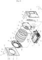
FIG. 1 ,FIG. 2 , andFIG. 3 show an example of a laundry treatment apparatus. -
FIG. 4 shows examples of a circulation flow passage and a heat exchange unit. -
FIG. 5 andFIG. 6 show examples of a support unit and a drain unit. -
FIG. 7 andFIG. 8 show an example of a condensate removal unit. -
FIG. 9 shows another embodiment of the condensate removal unit. -
FIG. 10 shows an example of a control method for the laundry treatment apparatus. - Hereinafter, preferred embodiments of a laundry treatment apparatus and a control method for the same will be described in detail with reference to the accompanying drawings.
- As shown in
FIG. 1 , alaundry treatment apparatus 100 may be configured to include acabinet 1. Within the cabinet, an accommodation unit provided within thecabinet 1 to accommodate an object to be dried (referred to as laundry hereinafter), a circulation flow passage and a heat exchange unit, which are configured to remove moisture from the laundry in the accommodation unit, and a heat exchange unit. - The
cabinet 1 may be configured to include afront surface 11 disposed at a front side of the laundry treatment apparatus, a rear surface disposed at a rear side of the laundry treatment apparatus, and abase 13 configured to form a bottom surface of the laundry treatment apparatus. - A control panel may be provided at the
front surface 11. The control panel may be configured to include adisplay 114 configured to display a control command selectable by the user, and aninput unit 113 configured to enable the user to select the control command displayed on thedisplay 114. - As shown in
FIG. 2 , acabinet access port 111 for loading and unloading of laundry is provided at thefront surface 11. Thecabinet access port 111 may be configured to be closed by adoor 115 pivotably mounted to thefront surface 11. - As shown in
FIG. 3 , the accommodation unit may be constituted by adrum 17 rotatably provided within thecabinet 1. Thedrum 17 may be configured to include acylindrical drum body 171 opened at a front surface and a rear surface thereof. - In order to rotatably support the
drum body 171, thecabinet 1 may be configured to include afront panel 14 configured to rotatably support the front surface of thedrum body 171 and arear panel 15 configured to rotatably support the rear surface of thedrum body 171. - The
front panel 14 may be configured to include afront panel body 141 fixed to thefront surface 11 or thecabinet 1, adrum access port 142 configured to extend through thefront panel body 141, and adrum exhaust hole 143 configured to discharge air in thedrum body 171 into thecirculation flow passage 2. - The
drum access port 142 may be configured to be connected to thecabinet access port 111. Accordingly, when thedoor 115 opens thecabinet access port 111, the user may load laundry in thedrum body 171 or may unload laundry from thedrum body 171 through thecabinet access port 111 and thedrum access port 142. - For filtration of air discharged from the
drum body 171, a filter attachable to or detachable from thefront panel body 141 may be provided at thedrum exhaust hole 143. - The
rear panel 15 may be configured to include arear panel body 151 fixed to therear surface 12 or thecabinet 1, and adrum supply hole 152 configured to extend through therear panel body 151. - The
drum body 171 is rotatable by a driver 18 provided within thecabinet 1. The driver 18 may be configured through inclusion of adrum motor 181 fixed to thebase 13, and a belt 182 configured to interconnect a rotation shaft of thedrum motor 181 and a circumferential surface of thedrum body 171. - In order to agitate laundry in the
drum body 171, alifter 172 may be further provided within thedrum body 171. Thelifter 172 may be constituted by a board protruding from the circumferential surface of thedrum body 171 toward a rotation center of thedrum body 171. - The
circulation flow passage 2 may be configured to include afirst duct 21 connected to thedrum exhaust hole 143, asecond duct 22 connected to thedrum supply hole 152, and a third duct 23 (a connection duct) configured to interconnect thefirst duct 21 and thesecond duct 22. Theconnection duct 23 may be configured to be fixed to thebase 13. - As shown in
FIG. 4 , theheat exchange unit 3 may be configured to include acirculation fan 36 configured to move air along thecirculation flow passage 2, and a heat pump 31-32-33-34-35 configured to sequentially execute dehumidification and heating of air moving along thecirculation flow passage 2. - The
circulation fan 36 may be configured to include a fan impeller 361 disposed at the inside of thecirculation flow passage 2, and afan motor 362 disposed at the outside of thecirculation flow passage 2 to rotate the fan impeller 361. - The heat pump may be configured to include a
refrigerant tube 33 configured to form a flow path through which refrigerant circulates, acompressor 34 configured to force the refrigerant to move along therefrigerant tube 33, afirst heat exchanger 31 fixed to therefrigerant tube 33 to transfer heat of air introduced into theconnection duct 23 to the refrigerant, asecond heat exchanger 32 fixed to therefrigerant tube 33 to transfer heat of the refrigerant to air emerging from thefirst heat exchanger 31, and acontrol valve 35 configured to adjust the pressure of the refrigerant. - The
connection duct 23 may be configured to include aduct body 231 fixed to thebase 13, and aduct cover 232 configured to form an upper surface of theduct body 231. As shown inFIG. 5 , theduct body 231 may be configured to include a first mountingportion 233, to which thefirst heat exchanger 31 is mounted, a second mountingportion 234, to which thesecond heat exchanger 32 is mounted, and a third mounting portion 235 (a fan mounting portion), in which the fan impeller 361 is rotatably received. - Air introduced into the
connection duct 23 is condensed while passing around thefirst heat exchanger 31, is heated while passing around thesecond heat exchanger 32, and is then moved to thedrum body 171 through thesecond duct 22 and thedrum supply hole 152. - A
support unit 4 configured to support a bottom surface of thefirst heat exchanger 31 may be provided at thecirculation flow passage 2. Thesupport unit 4 divides an interior of theconnection duct 23 into a mountingspace 233a, in which thefirst heat exchanger 31 is disposed, and adrain space 233b configured to guide condensate to the outside of the circulation flow passage 2 (seeFIG. 4 ). Thedrain space 233b is disposed under the mountingspace 233a, and adrain flow passage 5 is provided at thedrain space 233b. - As shown in
FIG. 6 , thesupport unit 4 may be configured to include asupport body 41 configured to support the bottom surface of thefirst heat exchanger 31, anextension body 42 configured to extend from thesupport body 41 toward thesecond heat exchanger 32, and a fastener 43-44 configured to fasten thesupport body 41 and theextension body 42 to theconnection duct 23. -
FIG. 6 shows, as an example, the case in which the fastener is configured through inclusion of fastening protrusions 43 protruding from opposite lateral surfaces of thesupport body 41, andfastening grooves 44 provided at theconnection duct 23 to receive the fastening protrusion 43. - A support body through
hole 411 is provided at thesupport body 41, and an extension body throughhole 421 is provided at theextension body 42. Accordingly, an inner space of the connection duct 23 (a space in which the first mounting portion is disposed) is divided into the mountingspace 233a and thedrain space 233b by thesupport body 41 and theextension body 42. However, the condensate present in the mountingspace 233a may move to thedrain space 233b through the support body throughhole 411 and the extension body throughhole 421. - The support body through
hole 411 may be configured to be disposed under thefirst exchanger 31, and the extension body throughhole 421 may be configured to be disposed between thefirst heat exchanger 31 and thesecond heat exchanger 32. These configurations are intended to prevent the condensate, which could not move to thedrain space 233b through the support body throughhole 411, from moving to thesecond heat exchanger 32 along a flow of air in theconnection duct 23. - A
water collection unit 6 configured to store condensate produced during condensation of air passing around thefirst heat exchanger 31 may be provided at thebase 13. - As shown in
FIG. 5 , thewater collection unit 6 may be disposed at the outside of thecirculation flow passage 2. In this case, thewater collection unit 6 may be connected to thedrain space 233b through adrain port 51 configured to extend through theconnection duct 23. It is preferred that thedrain flow passage 5 be provided at a bottom surface of theconnection duct 23 and be configured to guide condensate to thedrain port 51. - For natural drainage of the condensate (in order to enable the condensate in the drain flow passage to move to the water collection unit by gravity), a bottom surface of the
water collection unit 6 may be disposed at a lower level than thedrain port 51, and thedrain flow passage 5 may be configured to have an inclined surface downwardly inclined toward thedrain port 51. - As shown in
FIG. 3 , the condensate stored in thewater collection unit 6 may be discharged into adrain tank 8 through the drain unit 7. Thedrain tank 8 may be configured to be disposed at a higher level than thewater collection unit 6. - The
drain tank 8 may be configured to include adrawer 81 configured to be withdrawable from thecabinet 1 and to provide a space in which condensate is stored, and a drawer throughhole 82 configured to extend through an upper surface of thedrawer 81. - An
access port 112 for withdrawal of thedrawer 81 may be provided at thefront surface 11, and atank housing 16 configured to provide a space in which thedrawer 81 is accommodated may be provided within thecabinet 1. - The condensate discharged from the
water collection unit 6 through the drain unit 7 may move to thetank housing 16 through asupply tube 72, and the condensate discharged from thesupply tube 72 may move to an interior of thedrawer 81 through the drawer throughhole 82. - Meanwhile, when the condensate is supplied in an excessive amount to the
drawer 81, the condensate present in thedrawer 81 may be discharged into thetank housing 16 through the drawer throughhole 82. To this end, arecovery tube 72 may be further provided at the drain unit 7. Therecovery tube 72 is configured to interconnect a bottom surface of thetank housing 16 and thewater collection unit 6 and, as such, to guide the condensate discharged from thedrawer 81 to thewater collection unit 6. - As shown in
FIG. 5 , thewater collection unit 6 may be configured to include astorage body 61 provided at thebase 13 and configured to store condensate therein, and acover 62 configured to close an opened upper surface of thestorage body 61. Thedrain port 51 is provided at a circumferential surface of thestorage body 61 and, as such, communicates with an interior of thecirculation flow passage 2 through thedrain port 51. - A
supply port 622 and arecovery port 623 are provided at thecover 62. Thesupply tube 72 is connected to thesupply port 622, and therecovery tube 73 is connected to therecovery port 623. - In addition, a cover through
hole 621 and achamber 63, in which adrain pump 71 of the drain unit 7 is mounted, are provided at thecover 62. Thechamber 63 is fixed to thecover 62 such that thechamber 63 is disposed within thestorage body 61. As shown in the drawing, thechamber 63 may be configured to include achamber body 631 configured to have a cylindrical shape surrounding the cover throughhole 621, and asupply body 632 configured to connect an inner space of thechamber body 631 to thesupply port 622. - In this case, the
drain pump 71 may be configured to include adrain motor 711 fixed to thecover 62, and animpeller 713 fixed to arotation shaft 712 of thedrain motor 711 and disposed within thechamber body 631. - A
chamber inlet 633 is provided at a bottom surface of thechamber body 631 and, as such, condensate present in thestorage body 61 is introduced into thechamber body 631 and is then moved to thesupply port 622 through thesupply body 632 during rotation of theimpeller 713. The condensate moving to thesupply port 622 may then move to thedrain tank 8 through thesupply tube 72. - The
recovery port 623 extends through thecover 62 to communicate with thestorage body 61 and, as such, the condensate discharged from thedrain tank 8 may move to thestorage body 61 through therecovery tube 73 and therecovery port 623. - The laundry treatment apparatus having the above-described structure inevitably encounters a phenomenon in which condensate remains within the
storage body 61 because a space should be maintained between thechamber inlet 633 and a bottom surface of thestorage body 61. The phenomenon in which condensate remains within thestorage body 61 may become a factor making it difficult to hygienically manage thestorage body 61, theheat exchange unit 3, and thedrum 17. - In order to minimize problems caused by residual condensate in the
water collection unit 6, thelaundry treatment apparatus 100 may further include a condensate removal unit 9. - The condensate removal unit 9 is a means fixed to the base 13 or the
cover 62 and configured to supply heated air to thewater collection unit 6, thereby evaporating condensate present in thewater collection unit 6.FIG. 5 shows, as an example, the case in which the condensate removal unit 9 is fixed to thecover 62 to supply heated air to acommunication hole 624 of thecover 62. - As shown in
FIG. 7 , the condensate removal unit 9 may be configured to include ahot air supplier 91 configured to supply heated air to thewater collection unit 6, and avalve 92 configured to control opening/closing of thehot air supplier 91. - As shown in
FIG. 8 , thehot air supplier 91 may be configured to include asupply flow passage 911 configured to supply ambient air to thewater collection unit 6, asupply fan 916 configured to introduce ambient air to thesupply flow passage 911, and aheater 915 configured to heat the air introduced into thesupply flow passage 911. - The
supply flow passage 911 may be configured to include asupply duct 913 fixed to thecommunication hole 624, and aheating duct 912 connected to thesupply duct 913. Theheater 915 is mounted to theheating duct 912. In this case, thesupply duct 913 may extend toward an upper portion of the cover 62 (along a Y-axis), and theheating duct 912 may extend from one end of thesupply duct 913 in a longitudinal direction of the drum 17 (along a Z-axis). - When the
heating duct 912 extends in the longitudinal direction of thedrum 17, it may be possible to set theheating duct 912 to have a great length. The reason why theheating duct 912 is set to have a great length is to enable air introduced into theheating duct 912 to sufficiently exchange heat with the heater 915 (to increase the temperature of air supplied to the supply duct). - The
heating duct 912 may be configured to guide air present at the inside of thecabinet 1 or air present at the outside of thecabinet 1 to thesupply duct 913.FIG. 8 shows, as an example, the heating duct configured to guide air present at the inside of thecabinet 1 to thesupply duct 913. Thesupply fan 916 may be provided at an inlet of theheating duct 912. - Under the condition that the
supply flow passage 911 is always maintained in an opened state, a part of air emerging from thefirst heat exchanger 31 may be discharged through thewater collection unit 6 and thesupply flow passage 911 when theheat exchange unit 3 operates to dry laundry loaded in thedrum 17. Thevalve 91 is a means for solving such a problem. - The
valve 92 may be configured to open and close thecommunication hole 624 provided at thecover 62 or to open and close thesupply flow passage 911.FIG. 8 shows, as an example, the case in which thevalve 92 is configured to open and close anexhaust port 914 of thesupply duct 913. - The
valve 92 ofFIG. 8 may be configured to include a valve body 921 having a shape capable of opening and closing theexhaust port 914, and avalve motor 922 configured to control a rotation angle of the valve body 921. - When a drying procedure for drying of laundry or a sterilization procedure for sterilization of the drum or the heat exchangers is executed, condensate is stored in the
storage body 61. The condensate in thestorage body 61 is discharged into thedrain tank 8 through thesupply port 622 during rotation of theimpeller 713. The condensate remaining in thestorage body 61 after rotation of theimpeller 713 is stopped may be removed through operation of theheater 915 and thesupply fan 916 in an opened state of thesupply flow passage 911. - As shown in
FIG. 9 , the condensate removal unit 9 may be further provided with aconnection tube 917 configured to interconnect thecirculation flow passage 2 and thewater collection unit 6 and, as such, to guide a part of air emerging from thesecond heat exchanger 32 to thewater collection unit 6. Differently from the case shown in the drawing, the condensate removal unit 9 may be configured to include only theconnection tube 917 without thehot air supplier 91. - Furthermore, in order to reduce the time taken to remove the condensate in the
water collection unit 6, anactuator 93 may be further provided within thewater collection unit 6. Theactuator 93 may be constituted by an impeller (a water collection unit impeller) provided at the bottom surface of thestorage body 61 and configured to be rotated by a motor (disposed outside the water collection unit), an ultrasonic generator provided within thestorage body 61, or the like. -
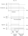
FIG. 10 shows an example of a control method for thelaundry treatment apparatus 100 as described above. The control method includes sterilization, flow passage opening, and condensate removal. - The sterilization is a procedure for supplying high-temperature dry air (air having a higher temperature than room temperature while having a lower humidity than the humidity of a space in which the laundry treatment apparatus is installed, by operating the
compressor 34 and thecirculation fan 36. It is preferred that, in the sterilization, thesupply flow passage 911 be maintained in a closed state. Accordingly, during execution of the sterilization, thevalve 92 is controlled to maintain thesupply flow passage 911 in the closed state. - The flow passage opening is a procedure for opening the
supply flow passage 911 by thevalve 92. The flow passage opening may be configured to start after the sterilization is executed for a predetermined reference time. - The condensate removal may start when the
supply flow passage 911 is opened through the flow passage opening. The condensate removal is a procedure for supplying heated air to the interior of thewater collection unit 6 by operating thesupply fan 916 and theheater 915. - The condensate removal may be configured to include a first period in which the
heater 915 operates continuously, and a second period in which theheater 915 repeats operation and stop thereof. The condensate removal may be configured to end simultaneously with the sterilization. - When the sterilization and the condensate removal end, the control method executes residual water removal. The residual water removal is a procedure for removing a residual condensate remaining in the
water collection unit 6 by operating thecirculation fan 36 and theheater 915 while stopping operation of thecompressor 34 and thesupply fan 916. The residual water removal may be configured to repeat operation and stop of theheater 915. - The residual water removal as described above is configured to be executed for a predetermined time after the sterilization ends. Accordingly, the control method of
FIG. 10 may prevent or minimize residual of the condensate in the water collection unit. - The structure and the control method of the laundry treatment apparatus as described above have been described as an example of the present disclosure. Accordingly, the scope of the present disclosure is not limited to the above-described structure and control method.
Claims (12)
- A laundry treatment apparatus comprising:a drum configured to provide a space for accommodating an object to be dried therein;a circulation flow passage configured to again supply, to the drum, air discharged from the drum;a heat exchange unit comprising a circulation fan configured to move air along the circulation flow passage, a first heat exchanger configured to dehumidify air moving along the circulation flow passage, and a second heat exchanger configured to heat air emerging from the first heat exchanger;a water collection unit connected to the circulation flow passage and to store condensate released from air passing around the first heat exchanger; anda condensate removal unit configured to supply heated air to the water collection unit, thereby removing the condensate within the water collection unit.
- The laundry treatment apparatus according to claim 1, wherein the condensate removal unit comprises: a supply flow passage configured to supply ambient air to the water collection unit; a supply fan configured to introduce ambient air to the supply flow passage; and a heater configured to heat the air introduced into the supply flow passage.
- The laundry treatment apparatus according to claim 2, wherein:the water collection unit comprises a storage body configured to store the condensate released from the air passing around the first heat exchanger, a cover configured to form an upper surface of the storage body, and a communication hole extending through the cover; andthe supply flow passage comprises a supply duct fixed to the communication hole, and a heating duct connected to the supply duct and configured for the heater to be mounted thereto.
- The laundry treatment apparatus according to claim 3, wherein the supply duct extends toward an upper portion of the cover, and the heating duct extends from one end of the supply duct in a longitudinal direction of the drum.
- The laundry treatment apparatus according to claim 3, further comprising:
a value configured to control opening and closing of the communication hole or the supply duct. - The laundry treatment apparatus according to claim 2, wherein the condensate removal unit further comprises a connection tube configured to interconnect the circulation flow passage and the water collection unit, thereby guiding a part of air emerging from the second heat exchanger to the water collection unit.
- The laundry treatment apparatus according to claim 2, wherein the condensate removal unit further comprises an actuator configured to form a flow of water within the water collection unit or to vibrate the condensate stored in the water collection unit.
- A control method for a laundry treatment apparatus comprising a drum configured to provide a space for accommodating an object to be dried therein, a circulation flow passage configured to again supply, to the drum, air discharged from the drum, a heat exchange unit comprising a circulation fan configured to move air along the circulation flow passage, a compressor configured to move refrigerant along a refrigerant tube, a first heat exchanger fixed to the refrigerant tube and configured to dehumidify air moving along the circulation flow passage, and a second heat exchanger fixed to the refrigerant tube and configured to heat air emerging from the first heat exchanger, a water collection unit connected to the circulation flow passage and to store condensate released from air passing around the first heat exchanger, and a condensate removal unit comprising a supply fan configured to supply ambient air to the water collection unit through a supply flow passage, a heater configured to heat air introduced into the supply flow passage, and a valve configured to control opening and closing of the supply flow passage, the control method comprising:sterilization of closing the supply flow passage by the valve, and supplying air to an interior of the drum by operating the compressor and the circulation fan;flow passage opening of controlling the valve to open the supply flow passage during execution of the sterilization; andcondensate removal of supplying heated air to the water collection unit by operating the supply fan and the heater when the supply flow passage is opened.
- The control method according to claim 8, wherein the flow passage opening starts after the sterilization is executed for a first predetermined time.
- The control method according to claim 8, wherein the condensate removal comprises:a first period in which the heater operates continuously; anda second period in which operation and stop of the heater is repeated after completion of the first period.
- The control method according to claim 8, further comprising:
residual water removal of removing condensate present within the water collection unit by stopping operation of the compressor and the supply fan and operating the circulation fan and the heater after ending of the sterilization and the condensate removal. - The control method according to claim 11, wherein the heater is configured to repeat operation and stop thereof during the residual water removal.
Applications Claiming Priority (2)
| Application Number | Priority Date | Filing Date | Title |
|---|---|---|---|
| KR1020220103295A KR20240025269A (en) | 2022-08-18 | 2022-08-18 | Laundry Treatment Apparatus and Control Method for the same |
| PCT/KR2023/010784 WO2024039096A1 (en) | 2022-08-18 | 2023-07-26 | Clothing processing apparatus and method for controlling clothing processing apparatus |
Publications (2)
| Publication Number | Publication Date |
|---|---|
| EP4556621A1 true EP4556621A1 (en) | 2025-05-21 |
| EP4556621A4 EP4556621A4 (en) | 2025-10-15 |
Family
ID=89941802
Family Applications (1)
| Application Number | Title | Priority Date | Filing Date |
|---|---|---|---|
| EP23855066.9A Pending EP4556621A4 (en) | 2022-08-18 | 2023-07-26 | CLOTHING TREATMENT APPARATUS AND METHOD FOR CONTROLLING A CLOTHING TREATMENT APPARATUS |
Country Status (4)
| Country | Link |
|---|---|
| EP (1) | EP4556621A4 (en) |
| KR (1) | KR20240025269A (en) |
| CN (1) | CN119790196A (en) |
| WO (1) | WO2024039096A1 (en) |
Families Citing this family (1)
| Publication number | Priority date | Publication date | Assignee | Title |
|---|---|---|---|---|
| KR20250128724A (en) | 2024-02-21 | 2025-08-28 | 주식회사 엘지에너지솔루션 | Apparatus and method for estimating capacity of battery |
Family Cites Families (12)
| Publication number | Priority date | Publication date | Assignee | Title |
|---|---|---|---|---|
| JP4388088B2 (en) * | 2007-02-16 | 2009-12-24 | 株式会社東芝 | Clothes dryer |
| KR101387497B1 (en) * | 2007-08-03 | 2014-04-21 | 엘지전자 주식회사 | Apparatus for processing clothes |
| KR20100096736A (en) * | 2009-02-25 | 2010-09-02 | 장동연 | Dryer |
| KR102821899B1 (en) | 2019-11-25 | 2025-06-18 | 엘지전자 주식회사 | Clothes dryer |
| KR20210087388A (en) * | 2020-01-02 | 2021-07-12 | 삼성전자주식회사 | Laundry drying apparatus and control method thereof |
| WO2021137487A1 (en) * | 2020-01-02 | 2021-07-08 | 삼성전자주식회사 | Dryer and control method therefor |
| KR102836922B1 (en) * | 2020-02-20 | 2025-07-22 | 엘지전자 주식회사 | Laundry Treatment Apparatus and Control Method for the same |
| KR102846005B1 (en) * | 2020-03-03 | 2025-08-13 | 엘지전자 주식회사 | laundry treatment apparatus |
| KR102834306B1 (en) * | 2020-03-04 | 2025-07-15 | 엘지전자 주식회사 | Laundry drying machine and controlling method of laundry drying machine |
| KR102814544B1 (en) * | 2020-03-30 | 2025-05-29 | 엘지전자 주식회사 | laundry treatment apparatus and operating method of the apparatus |
| AU2021356514A1 (en) * | 2020-10-05 | 2023-06-08 | Lg Electronics Inc. | Clothing processing apparatus |
| KR20220102479A (en) * | 2021-01-13 | 2022-07-20 | 엘지전자 주식회사 | Dishwasher and control method thereof |
-
2022
- 2022-08-18 KR KR1020220103295A patent/KR20240025269A/en active Pending
-
2023
- 2023-07-26 CN CN202380060184.8A patent/CN119790196A/en active Pending
- 2023-07-26 EP EP23855066.9A patent/EP4556621A4/en active Pending
- 2023-07-26 WO PCT/KR2023/010784 patent/WO2024039096A1/en not_active Ceased
Also Published As
| Publication number | Publication date |
|---|---|
| EP4556621A4 (en) | 2025-10-15 |
| CN119790196A (en) | 2025-04-08 |
| KR20240025269A (en) | 2024-02-27 |
| WO2024039096A1 (en) | 2024-02-22 |
Similar Documents
| Publication | Publication Date | Title |
|---|---|---|
| US7418789B2 (en) | Combination dryer and method thereof | |
| KR101414635B1 (en) | Cloth treating apparatus | |
| US20150059413A1 (en) | Laundry treatment apparatus | |
| EP4556622A1 (en) | Clothing processing apparatus and method for controlling clothing processing apparatus | |
| US20250019890A1 (en) | Laundry treating apparatus | |
| EP3015591B1 (en) | Clothes treating apparatus and control method thereof | |
| EP2743394A1 (en) | Heat pump laundry treatment apparatus | |
| KR102845073B1 (en) | Laudnry Treatment Apparatus | |
| EP4556621A1 (en) | Clothing processing apparatus and method for controlling clothing processing apparatus | |
| US12123125B2 (en) | Apparatus for treating laundry and control method therefor | |
| KR101314625B1 (en) | Clothes Treating Apparatus | |
| JP7319028B2 (en) | clothes dryer | |
| CN100540789C (en) | Tumble Washer Dryer | |
| KR20240025268A (en) | Laundry Treatment Apparatus and Control Method for the same | |
| KR101486358B1 (en) | Apparatus for processing clothes | |
| KR101542375B1 (en) | Apparatus for processing clothes | |
| KR102628094B1 (en) | Laundry Treating Apparatus | |
| EP1925713B1 (en) | Laundry drier with an additional controlled-temperature compartment for delicate laundry | |
| US20250163636A1 (en) | Clothes treatment apparatus | |
| KR102917894B1 (en) | Laundry Treatment Apparatus | |
| KR102729799B1 (en) | Laundry treatment apparatus | |
| KR20230126092A (en) | Laundry Treatment Apparatus | |
| JP2024024481A (en) | clothes dryer |
Legal Events
| Date | Code | Title | Description |
|---|---|---|---|
| STAA | Information on the status of an ep patent application or granted ep patent |
Free format text: STATUS: THE INTERNATIONAL PUBLICATION HAS BEEN MADE |
|
| PUAI | Public reference made under article 153(3) epc to a published international application that has entered the european phase |
Free format text: ORIGINAL CODE: 0009012 |
|
| STAA | Information on the status of an ep patent application or granted ep patent |
Free format text: STATUS: REQUEST FOR EXAMINATION WAS MADE |
|
| 17P | Request for examination filed |
Effective date: 20250213 |
|
| AK | Designated contracting states |
Kind code of ref document: A1 Designated state(s): AL AT BE BG CH CY CZ DE DK EE ES FI FR GB GR HR HU IE IS IT LI LT LU LV MC ME MK MT NL NO PL PT RO RS SE SI SK SM TR |
|
| A4 | Supplementary search report drawn up and despatched |
Effective date: 20250917 |
|
| RIC1 | Information provided on ipc code assigned before grant |
Ipc: D06F 58/26 20060101AFI20250911BHEP Ipc: D06F 58/20 20060101ALI20250911BHEP Ipc: D06F 58/24 20060101ALI20250911BHEP Ipc: D06F 58/38 20200101ALI20250911BHEP Ipc: D06F 58/45 20200101ALI20250911BHEP Ipc: D06F 103/58 20200101ALN20250911BHEP Ipc: D06F 103/68 20200101ALN20250911BHEP Ipc: D06F 105/30 20200101ALN20250911BHEP Ipc: D06F 105/36 20200101ALN20250911BHEP Ipc: D06F 105/28 20200101ALN20250911BHEP |
|
| DAV | Request for validation of the european patent (deleted) | ||
| DAX | Request for extension of the european patent (deleted) |