EP4556361A1 - Floating-type stand-column turbulent flow structure, floating-type stand column and floating-type fan - Google Patents
Floating-type stand-column turbulent flow structure, floating-type stand column and floating-type fan Download PDFInfo
- Publication number
- EP4556361A1 EP4556361A1 EP23838386.3A EP23838386A EP4556361A1 EP 4556361 A1 EP4556361 A1 EP 4556361A1 EP 23838386 A EP23838386 A EP 23838386A EP 4556361 A1 EP4556361 A1 EP 4556361A1
- Authority
- EP
- European Patent Office
- Prior art keywords
- column
- gear
- spoiler
- connecting rod
- floating
- Prior art date
- Legal status (The legal status is an assumption and is not a legal conclusion. Google has not performed a legal analysis and makes no representation as to the accuracy of the status listed.)
- Granted
Links
Images




Classifications
-
- B—PERFORMING OPERATIONS; TRANSPORTING
- B63—SHIPS OR OTHER WATERBORNE VESSELS; RELATED EQUIPMENT
- B63B—SHIPS OR OTHER WATERBORNE VESSELS; EQUIPMENT FOR SHIPPING
- B63B39/00—Equipment to decrease pitch, roll, or like unwanted vessel movements; Apparatus for indicating vessel attitude
- B63B39/06—Equipment to decrease pitch, roll, or like unwanted vessel movements; Apparatus for indicating vessel attitude to decrease vessel movements by using foils acting on ambient water
-
- B—PERFORMING OPERATIONS; TRANSPORTING
- B63—SHIPS OR OTHER WATERBORNE VESSELS; RELATED EQUIPMENT
- B63B—SHIPS OR OTHER WATERBORNE VESSELS; EQUIPMENT FOR SHIPPING
- B63B1/00—Hydrodynamic or hydrostatic features of hulls or of hydrofoils
- B63B1/02—Hydrodynamic or hydrostatic features of hulls or of hydrofoils deriving lift mainly from water displacement
- B63B1/04—Hydrodynamic or hydrostatic features of hulls or of hydrofoils deriving lift mainly from water displacement with single hull
- B63B1/048—Hydrodynamic or hydrostatic features of hulls or of hydrofoils deriving lift mainly from water displacement with single hull with hull extending principally vertically
-
- B—PERFORMING OPERATIONS; TRANSPORTING
- B63—SHIPS OR OTHER WATERBORNE VESSELS; RELATED EQUIPMENT
- B63B—SHIPS OR OTHER WATERBORNE VESSELS; EQUIPMENT FOR SHIPPING
- B63B35/00—Vessels or similar floating structures specially adapted for specific purposes and not otherwise provided for
- B63B35/44—Floating buildings, stores, drilling platforms, or workshops, e.g. carrying water-oil separating devices
-
- B—PERFORMING OPERATIONS; TRANSPORTING
- B63—SHIPS OR OTHER WATERBORNE VESSELS; RELATED EQUIPMENT
- B63B—SHIPS OR OTHER WATERBORNE VESSELS; EQUIPMENT FOR SHIPPING
- B63B43/00—Improving safety of vessels, e.g. damage control, not otherwise provided for
- B63B43/02—Improving safety of vessels, e.g. damage control, not otherwise provided for reducing risk of capsizing or sinking
- B63B43/04—Improving safety of vessels, e.g. damage control, not otherwise provided for reducing risk of capsizing or sinking by improving stability
-
- F—MECHANICAL ENGINEERING; LIGHTING; HEATING; WEAPONS; BLASTING
- F03—MACHINES OR ENGINES FOR LIQUIDS; WIND, SPRING, OR WEIGHT MOTORS; PRODUCING MECHANICAL POWER OR A REACTIVE PROPULSIVE THRUST, NOT OTHERWISE PROVIDED FOR
- F03D—WIND MOTORS
- F03D13/00—Assembly, mounting or commissioning of wind motors; Arrangements specially adapted for transporting wind motor components
- F03D13/20—Arrangements for mounting or supporting wind motors; Masts or towers for wind motors
- F03D13/25—Arrangements for mounting or supporting wind motors; Masts or towers for wind motors specially adapted for offshore installation
-
- B—PERFORMING OPERATIONS; TRANSPORTING
- B63—SHIPS OR OTHER WATERBORNE VESSELS; RELATED EQUIPMENT
- B63B—SHIPS OR OTHER WATERBORNE VESSELS; EQUIPMENT FOR SHIPPING
- B63B1/00—Hydrodynamic or hydrostatic features of hulls or of hydrofoils
- B63B1/02—Hydrodynamic or hydrostatic features of hulls or of hydrofoils deriving lift mainly from water displacement
- B63B1/04—Hydrodynamic or hydrostatic features of hulls or of hydrofoils deriving lift mainly from water displacement with single hull
- B63B2001/044—Hydrodynamic or hydrostatic features of hulls or of hydrofoils deriving lift mainly from water displacement with single hull with a small waterline area compared to total displacement, e.g. of semi-submersible type
-
- B—PERFORMING OPERATIONS; TRANSPORTING
- B63—SHIPS OR OTHER WATERBORNE VESSELS; RELATED EQUIPMENT
- B63B—SHIPS OR OTHER WATERBORNE VESSELS; EQUIPMENT FOR SHIPPING
- B63B35/00—Vessels or similar floating structures specially adapted for specific purposes and not otherwise provided for
- B63B35/44—Floating buildings, stores, drilling platforms, or workshops, e.g. carrying water-oil separating devices
- B63B2035/4433—Floating structures carrying electric power plants
- B63B2035/446—Floating structures carrying electric power plants for converting wind energy into electric energy
-
- B—PERFORMING OPERATIONS; TRANSPORTING
- B63—SHIPS OR OTHER WATERBORNE VESSELS; RELATED EQUIPMENT
- B63B—SHIPS OR OTHER WATERBORNE VESSELS; EQUIPMENT FOR SHIPPING
- B63B39/00—Equipment to decrease pitch, roll, or like unwanted vessel movements; Apparatus for indicating vessel attitude
- B63B39/06—Equipment to decrease pitch, roll, or like unwanted vessel movements; Apparatus for indicating vessel attitude to decrease vessel movements by using foils acting on ambient water
- B63B2039/067—Equipment to decrease pitch, roll, or like unwanted vessel movements; Apparatus for indicating vessel attitude to decrease vessel movements by using foils acting on ambient water effecting motion dampening by means of fixed or movable resistance bodies, e.g. by bilge keels
-
- F—MECHANICAL ENGINEERING; LIGHTING; HEATING; WEAPONS; BLASTING
- F03—MACHINES OR ENGINES FOR LIQUIDS; WIND, SPRING, OR WEIGHT MOTORS; PRODUCING MECHANICAL POWER OR A REACTIVE PROPULSIVE THRUST, NOT OTHERWISE PROVIDED FOR
- F03D—WIND MOTORS
- F03D13/00—Assembly, mounting or commissioning of wind motors; Arrangements specially adapted for transporting wind motor components
- F03D13/20—Arrangements for mounting or supporting wind motors; Masts or towers for wind motors
- F03D13/25—Arrangements for mounting or supporting wind motors; Masts or towers for wind motors specially adapted for offshore installation
- F03D13/256—Arrangements for mounting or supporting wind motors; Masts or towers for wind motors specially adapted for offshore installation on a floating support, i.e. floating wind motors
-
- F—MECHANICAL ENGINEERING; LIGHTING; HEATING; WEAPONS; BLASTING
- F05—INDEXING SCHEMES RELATING TO ENGINES OR PUMPS IN VARIOUS SUBCLASSES OF CLASSES F01-F04
- F05B—INDEXING SCHEME RELATING TO WIND, SPRING, WEIGHT, INERTIA OR LIKE MOTORS, TO MACHINES OR ENGINES FOR LIQUIDS COVERED BY SUBCLASSES F03B, F03D AND F03G
- F05B2240/00—Components
- F05B2240/90—Mounting on supporting structures or systems
- F05B2240/93—Mounting on supporting structures or systems on a structure floating on a liquid surface
-
- F—MECHANICAL ENGINEERING; LIGHTING; HEATING; WEAPONS; BLASTING
- F05—INDEXING SCHEMES RELATING TO ENGINES OR PUMPS IN VARIOUS SUBCLASSES OF CLASSES F01-F04
- F05B—INDEXING SCHEME RELATING TO WIND, SPRING, WEIGHT, INERTIA OR LIKE MOTORS, TO MACHINES OR ENGINES FOR LIQUIDS COVERED BY SUBCLASSES F03B, F03D AND F03G
- F05B2240/00—Components
- F05B2240/90—Mounting on supporting structures or systems
- F05B2240/95—Mounting on supporting structures or systems offshore
-
- Y—GENERAL TAGGING OF NEW TECHNOLOGICAL DEVELOPMENTS; GENERAL TAGGING OF CROSS-SECTIONAL TECHNOLOGIES SPANNING OVER SEVERAL SECTIONS OF THE IPC; TECHNICAL SUBJECTS COVERED BY FORMER USPC CROSS-REFERENCE ART COLLECTIONS [XRACs] AND DIGESTS
- Y02—TECHNOLOGIES OR APPLICATIONS FOR MITIGATION OR ADAPTATION AGAINST CLIMATE CHANGE
- Y02E—REDUCTION OF GREENHOUSE GAS [GHG] EMISSIONS, RELATED TO ENERGY GENERATION, TRANSMISSION OR DISTRIBUTION
- Y02E10/00—Energy generation through renewable energy sources
- Y02E10/70—Wind energy
- Y02E10/72—Wind turbines with rotation axis in wind direction
-
- Y—GENERAL TAGGING OF NEW TECHNOLOGICAL DEVELOPMENTS; GENERAL TAGGING OF CROSS-SECTIONAL TECHNOLOGIES SPANNING OVER SEVERAL SECTIONS OF THE IPC; TECHNICAL SUBJECTS COVERED BY FORMER USPC CROSS-REFERENCE ART COLLECTIONS [XRACs] AND DIGESTS
- Y02—TECHNOLOGIES OR APPLICATIONS FOR MITIGATION OR ADAPTATION AGAINST CLIMATE CHANGE
- Y02E—REDUCTION OF GREENHOUSE GAS [GHG] EMISSIONS, RELATED TO ENERGY GENERATION, TRANSMISSION OR DISTRIBUTION
- Y02E10/00—Energy generation through renewable energy sources
- Y02E10/70—Wind energy
- Y02E10/727—Offshore wind turbines
Definitions
- the disclosure relates to the technical field of spoiler structures, in particular to a floating column spoiler structure, a floating column, and a floating wind turbine.
- offshore wind turbine is usually equipped with floating platform to support floating wind turbine, and the bottom of the floating platform is usually equipped with cylindrical floating column.
- karman vortex bits often occur around the floating column, which causes vortex-induced vibration of the floating column, leading to the phenomenon that the floating wind turbine often have too large inclination angle or too large roll and pitch angle, which reduces the stability of the floating wind turbine and affects the smooth power output of the floating wind turbine.
- the purpose of the disclosure is to provide a floating column spoiler structure to improve the stability of a floating wind turbine.
- a floating column spoiler structure which includes:
- each of the spoiler plates is rotatably arranged at the first end of the first connecting rod and the first end of the second connecting rod.
- the first end of the first connecting rod and the first end of the second connecting rod are connected by a ball hinge.
- each of the spoiler plates includes spoiler nets or spoiler nails.
- a number of the lifting and unfolding assemblies corresponding to each of the spoiler plates is three, and the lifting and unfolding assemblies includes a first lifting and unfolding assembly, a second lifting and unfolding assembly and a third lifting and unfolding assembly, and connection positions of the first lifting and unfolding assembly, the second lifting and unfolding assembly and the third lifting and unfolding assembly with corresponding one of the spoiler plates are distributed in a triangle shape.
- the lifting gear teeth are directly arranged on the outer circumferential wall of the column, or toothed belts are arranged on the outer circumferential wall of the column, and the lifting gear teeth are located on the toothed belts.
- the first gear and the second gear are respectively arranged on the outer circumferential wall of the column through a first gear mounting piece and a second gear mounting piece, and the first gear mounting piece and the second gear mounting piece are slidably connected to the outer circumferential wall of the column.
- the floating column spoiler structure further including a central control system, a water body flow velocity monitoring system and a wind and wave environment monitoring system, as well as a first pushing piece for pushing the second end of the first connecting rod to lift and a second pushing piece for pushing the second end of the second connecting rod to lift, where the central control system is capable of transmitting signals with the water body flow velocity monitoring system, the wind and wave environment monitoring system, the first pushing piece and the second pushing piece.
- a floating column including a floating column spoiler structure as described above.
- a floating wind turbine including a floating column spoiler structure as described above.
- the floating column spoiler structure provided by this disclosure
- the second end of the first connecting rod is rotatably connected with the first gear
- the second end of the second connecting rod is rotatably connected with the second gear, which are sequentially arranged on the outer circumferential wall of the column from top to bottom along the axial direction of the column, and the outer circumferential wall of the column is provided with lifting gear teeth capable of meshing with the first gear and the second gear; Therefore, the distance between the first gear and the second gear can be adjusted by moving at least one of the first gear and the second gear along the axial direction of the column, so that the distance between the second end of the first connecting rod and the second end of the second connecting rod can be adjusted, so that the distance between the first end of the first connecting rod and the first end of the second connecting rod and the outer circumferential wall of the column can be adjusted, and the distance between the spoiler arranged at the first end of the first connecting rod and the first
- the floating column spoiler structure provided by this disclosure
- the first end of the first connecting rod and the first end of the second connecting rod are rotatably connected
- the second end of the first connecting rod is rotatably connected with the first gear
- the second end of the second connecting rod is rotatably connected with the second gear
- the first gear and the second gear are sequentially arranged on an outer circumferential wall of the column from top to bottom along an axial direction of the column, and the outer circumferential wall of the column is provided with lifting gear teeth being capable of meshing with the first gear and the second gear.
- the distance between the first gear and the second gear can be adjusted by moving at least one of the first gear and the second gear along the axial direction of the column, so that the distance between the second end of the first connecting rod and the second end of the second connecting rod can be adjusted, so that the distance between the first end of the first connecting rod and the first end of the second connecting rod and the outer circumferential wall of the column can be adjusted, so that the distance between the spoiler plate arranged at the first end of the first connecting rod and the first end of the second connecting rod and the outer circumferential wall of the column can be increased or decreased. Therefore, the floating column spoiler structure provided by the disclosure has the following beneficial effects:
- the core of this disclosure is to provide a floating column spoiler structure to improve the stability of floating wind turbine.
- an embodiment of the disclosure discloses a floating column spoiler structure, which includes spoiler plates 100 and lifting and unfolding assemblies 200.
- the lifting and unfolding assembly 200 connects the spoiler plate 100 and the column 300.
- the lifting and unfolding assembly 200 includes a first connecting rod 201, a second connecting rod 202, a first gear 203 and a second gear 204, and the first end of the first connecting rod 201 is rotatably connected with the first end of the second connecting rod 202, and the spoiler plate 100 is arranged at the first end of the first connecting rod 201 and the first end of the second connecting rod 202.
- the second end of the first connecting rod 201 is rotatably connected with the first gear 203, and the second end of the second connecting rod 202 is rotatably connected with the second gear 204.
- the first gear 203 and the second gear 204 are sequentially arranged on the outer circumferential wall of the column 300 from top to bottom along the axial direction of the column 300, and the outer circumferential wall of the column 300 is provided with lifting gear teeth that can mesh with the first gear 203 and the second gear 204.
- the first gear 203 and the second gear 204 are sequentially arranged on the outer circumferential wall of the column 300 from top to bottom along the axial direction of the column 300, and the outer circumferential wall of the column 300 is provided with lifting gear teeth capable of meshing with the first gear 203 and the second gear 204; therefore, the distance between the first gear 203 and the second gear 204 can be adjusted by moving at least one of the first gear 203 and the second gear 204 along the axial direction of the column 300, so that the distance between the second end of the first connecting rod 201 and the second end of the second connecting rod 202 can be adjusted, so that the distance between the first end of the first connecting rod
- the spoiler plate 100 can be a spoiler net, a plate with spoiler nails, a spoiler plate with spoiler blades, etc., as long as it is a structural that can meet the spoiler requirements, it belongs to the protection scope of the disclosure.
- the spoiler plate 100 is a spoiler net to play a spoiler role through the mesh of the spoiler net.
- the spoiler plate 100 includes a spoiler plate body and spoiler nails arranged on the spoiler plate body to play a spoiler role through the raised spoiler nails.
- a number of the lifting and unfolding assemblies 200 corresponding to each of the spoiler plates 100 is three, and the lifting and unfolding assemblies 200 includes a first lifting and unfolding assembly, a second lifting and unfolding assembly and a third lifting and unfolding assembly, and connection positions of the first lifting and unfolding assembly, the second lifting and unfolding assembly and the third lifting and unfolding assembly with corresponding one of the spoiler plates 100 are distributed in a triangle shape, so as to form a triangular support structure for the spoiler plate 100 and improve the stability of the spoiler plate 100.
- the lifting gear teeth can be directly arranged on the outer circumferential wall of the column 300, that is, the lifting gear teeth and the column 300 have an integrated structure.
- the outer circumferential wall of the column 300 is provided with toothed belts 301, and the lifting gear teeth are located on the toothed belts 301, that is, the column 300 and the toothed belts with a split structure are all within the protection scope of the disclosure as long as they can meet the use requirements.
- first gear 203 and the second gear 204 are respectively arranged on the outer circumferential wall of the column 300 through the first gear 203 mounting piece and the second gear 204 mounting piece, and the first gear 203 mounting piece and the second gear 204 mounting piece are slidably connected to the outer circumferential wall of the column 300, so that the first gear 203 and the second gear 204 can be meshed and rolled on the lifting gear teeth, thereby adjusting and enabling the spoiler plate 100 to be lifted, unfolded and retracted.
- the floating column turbulence structure also includes a central control system, a water body flow velocity monitoring system and a wind and wave environment monitoring system, as well as a first pushing piece for pushing the second end of the first connecting rod 201 to lift and a second pushing piece for pushing the second end of the second connecting rod 202 to lift, where the central control system is capable of transmitting signals with the water body flow velocity monitoring system, the wind and wave environment monitoring system, the first pushing piece and the second pushing piece.
- Seawater flow velocity information is monitored (including factors such as water flow velocity and direction) through a water body flow velocity monitoring system
- wave condition information is monitored (including factors such as wave height, period and wavelength) through a wind and wave environment monitoring system.
- the central control system After receiving seawater flow velocity information and wave condition information, the central control system estimates the movement situation of the floating column, and controls the first pushing piece and the second pushing piece to perform the pushing action according to the estimated movement situation of the floating column.
- the first pushing piece and the second pushing piece push the first connecting rod 201 and the second connecting rod 202 respectively, so that the height of the spoiler plate 100 can be adjusted and the state of the spoiler plate 100 can be switched between unfolding and retraction, so that the floating column spoiler structure can actively adjust the height and state of the spoiler plate 100 according to the water body flow rate and wind and wave environment, better reduce the vortex-induced vibration phenomenon, and improve the suppression effect on the rolling and pitching of the floating wind turbine, thereby improving the stability of the floating wind turbine and ensuring the stability of the floating wind turbine.
- the signal transmission mode between the central control system, the water body flow velocity monitoring system, the wind and wave environment monitoring system, the first pushing piece and the second pushing piece can be wired transmission or wireless transmission, as long as it can meet the signal transmission requirements, it belongs to the protection scope of the disclosure.
- the disclosure also provides a floating column and a floating wind turbine, both of which include the floating column spoiler structure, so that all the technical effects of the floating column spoiler structure are achieved, and the details are not repeated here.
- the anchor chain of the anchoring system 400 fixes the column 300 on the seabed to realize the positioning and fixing of the floating wind turbine, and the floating wind turbine is set in a preset sea area to generate electricity through offshore wind energy.
Landscapes
- Engineering & Computer Science (AREA)
- Mechanical Engineering (AREA)
- Chemical & Material Sciences (AREA)
- Combustion & Propulsion (AREA)
- Ocean & Marine Engineering (AREA)
- Sustainable Energy (AREA)
- Life Sciences & Earth Sciences (AREA)
- Sustainable Development (AREA)
- General Engineering & Computer Science (AREA)
- Architecture (AREA)
- Civil Engineering (AREA)
- Structural Engineering (AREA)
- Fluid Mechanics (AREA)
- Physics & Mathematics (AREA)
- Wind Motors (AREA)
- Structures Of Non-Positive Displacement Pumps (AREA)
Abstract
Description
- The disclosure relates to the technical field of spoiler structures, in particular to a floating column spoiler structure, a floating column, and a floating wind turbine.
- At present, offshore wind turbine is usually equipped with floating platform to support floating wind turbine, and the bottom of the floating platform is usually equipped with cylindrical floating column. When the ocean current flows through the floating column, karman vortex bits often occur around the floating column, which causes vortex-induced vibration of the floating column, leading to the phenomenon that the floating wind turbine often have too large inclination angle or too large roll and pitch angle, which reduces the stability of the floating wind turbine and affects the smooth power output of the floating wind turbine.
- Therefore, how to improve the stability of floating wind turbine is a technical problem that needs to be solved by those skilled in this field at present.
- In view of this, the purpose of the disclosure is to provide a floating column spoiler structure to improve the stability of a floating wind turbine.
- In order to achieve the above purpose, the disclosure provides the following technical scheme:
a floating column spoiler structure is provided, which includes: - multiple spoiler plates;
- lifting and unfolding assemblies connecting each of the spoiler plates and a column; where each of the lifting and unfolding assemblies includes a first connecting rod, a second connecting rod, a first gear and a second gear; a first end of the first connecting rod is rotatably connected with a first end of the second connecting rod, and each of the spoiler plates is arranged at the first end of the first connecting rod and the first end of the second connecting rod; a second end of the first connecting rod is rotatably connected with the first gear, and a second end of the second connecting rod is rotatably connected with the second gear; the first gear and the second gear are sequentially arranged on an outer circumferential wall of the column from top to bottom along an axial direction of the column, and the outer circumferential wall of the column is provided with lifting gear teeth being capable of meshing with the first gear and the second gear.
- Optionally, in the floating column spoiler structure, each of the spoiler plates is rotatably arranged at the first end of the first connecting rod and the first end of the second connecting rod.
- Optionally, in the floating column spoiler structure, the first end of the first connecting rod and the first end of the second connecting rod are connected by a ball hinge.
- Optionally, in the floating column spoiler structure, each of the spoiler plates includes spoiler nets or spoiler nails.
- Optionally, in the floating column spoiler structure, a number of the lifting and unfolding assemblies corresponding to each of the spoiler plates is three, and the lifting and unfolding assemblies includes a first lifting and unfolding assembly, a second lifting and unfolding assembly and a third lifting and unfolding assembly, and connection positions of the first lifting and unfolding assembly, the second lifting and unfolding assembly and the third lifting and unfolding assembly with corresponding one of the spoiler plates are distributed in a triangle shape.
- Optionally, in the floating column spoiler structure, the lifting gear teeth are directly arranged on the outer circumferential wall of the column, or toothed belts are arranged on the outer circumferential wall of the column, and the lifting gear teeth are located on the toothed belts.
- Optionally, in the floating column spoiler structure, the first gear and the second gear are respectively arranged on the outer circumferential wall of the column through a first gear mounting piece and a second gear mounting piece, and the first gear mounting piece and the second gear mounting piece are slidably connected to the outer circumferential wall of the column.
- Optionally, in the floating column spoiler structure, further including a central control system, a water body flow velocity monitoring system and a wind and wave environment monitoring system, as well as a first pushing piece for pushing the second end of the first connecting rod to lift and a second pushing piece for pushing the second end of the second connecting rod to lift, where the central control system is capable of transmitting signals with the water body flow velocity monitoring system, the wind and wave environment monitoring system, the first pushing piece and the second pushing piece.
- A floating column, including a floating column spoiler structure as described above.
- A floating wind turbine, including a floating column spoiler structure as described above.
- When the floating column spoiler structure provided by this disclosure is used, because the first end of the first connecting rod and the first end of the second connecting rod are rotatably connected, the second end of the first connecting rod is rotatably connected with the first gear and the second end of the second connecting rod is rotatably connected with the second gear, which are sequentially arranged on the outer circumferential wall of the column from top to bottom along the axial direction of the column, and the outer circumferential wall of the column is provided with lifting gear teeth capable of meshing with the first gear and the second gear; Therefore, the distance between the first gear and the second gear can be adjusted by moving at least one of the first gear and the second gear along the axial direction of the column, so that the distance between the second end of the first connecting rod and the second end of the second connecting rod can be adjusted, so that the distance between the first end of the first connecting rod and the first end of the second connecting rod and the outer circumferential wall of the column can be adjusted, and the distance between the spoiler arranged at the first end of the first connecting rod and the first end of the second connecting rod and the outer circumferential wall of the column can be increased or decreased. Therefore, the floating column spoiler structure provided by the invention has the following beneficial effects.
- When the floating column spoiler structure provided by this disclosure is used, because the first end of the first connecting rod and the first end of the second connecting rod are rotatably connected, the second end of the first connecting rod is rotatably connected with the first gear and the second end of the second connecting rod is rotatably connected with the second gear, the first gear and the second gear are sequentially arranged on an outer circumferential wall of the column from top to bottom along an axial direction of the column, and the outer circumferential wall of the column is provided with lifting gear teeth being capable of meshing with the first gear and the second gear. Therefore, the distance between the first gear and the second gear can be adjusted by moving at least one of the first gear and the second gear along the axial direction of the column, so that the distance between the second end of the first connecting rod and the second end of the second connecting rod can be adjusted, so that the distance between the first end of the first connecting rod and the first end of the second connecting rod and the outer circumferential wall of the column can be adjusted, so that the distance between the spoiler plate arranged at the first end of the first connecting rod and the first end of the second connecting rod and the outer circumferential wall of the column can be increased or decreased. Therefore, the floating column spoiler structure provided by the disclosure has the following beneficial effects:
- 1. when the seawater velocity is high, at least one of the first gear and the second gear is first moved to reduce the distance between the first end of the first connecting rod and the first end of the second connecting rod and the column, and the spoiler plate is retracted, and then both the first gear and the second gear are raised along the lifting gear teeth, so that multiple spoiler plates are raised to a preset spoiler position, and then at least one of the first gear and the second gear is moved. The distance between the first end of the first connecting rod and the first end of the second connecting rod and the outer circumferential wall of the column is increased, so that the distance between the spoiler plate and the outer circumferential wall of the column is increased, and the unfolding function of the spoiler plate is realized; the karman vortex bits around the column are reduced through multiple unfolded spoiler plates, so that the vortex-induced vibration of the column is reduced, thereby reducing the inclination angle, the rolling angle and the pitching angle of the floating wind turbine, improving the stability of the floating wind turbine and enabling the power of the floating wind turbine to be stably output;
- 2. when the wind and waves are heavy, firstly, by moving at least one of the first gear and the second gear, the distances between the first end of the first connecting rod and the first end of the second connecting rod and the column are reduced, and the spoiler plates are retracted; then, both the first gear and the second gear are lowered along the lifting gear teeth, so that multiple spoiler plates are lowered to preset sagging positions, and the center of gravity of the floating column is lowered, so that the center of gravity of the whole floating platform is lowered; and then, at least one of the first gear and the second gear is moved, the distance between the first end of the first connecting rod and the first end of the second connecting rod and the outer circumferential wall of the column is increased, so that the distance between the spoiler plate and the outer circumferential wall of the column is increased, the spoiler plate is unfolded at a preset sagging position, the damping of the floating column is increased, the stability of the whole floating wind turbine is improved, and the power of the floating wind turbine is stably output;
- 3. when in a calm sea, at least one of the first gear and the second gear is moved to reduce the distance between the first end of the first connecting rod and the first end of the second connecting rod and the outer circumferential wall of the column, thereby reducing the distance between the spoiler plate and the outer circumferential wall of the column, and the spoiler plate is retracted to reduce the hydrodynamic force.
- In order to more clearly explain the embodiment of the disclosure or the technical scheme in the prior art, the drawings needed to be used in the description of the embodiment or the prior art will be briefly introduced below. Obviously, the drawings in the following description are only some embodiments of the disclosure, and for ordinary skilled in this field, other drawings can be obtained according to these drawings without creative efforts.
-
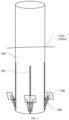
FIG. 1 is a schematic structural diagram of a floating column spoiler structure when unfolded according to an embodiment of the disclosure; -
FIG. 2 is a schematic structural diagram of the floating column spoiler structure when retracted according to an embodiment of the disclosure; -
FIG. 3 is a schematic structural diagram of the floating column spoiler structure when it rises to the preset spoiler position and the spoiler plate is retracted according to an embodiment of the disclosure; -
FIG. 4 is a schematic structural diagram of the floating column spoiler structure when it rises to the preset spoiler position and the spoiler plate is unfolded according to an embodiment of the disclosure; -
FIG. 5 is a schematic structural diagram of the floating column spoiler structure when the spoiler plate is retracted before descending according to an embodiment of the disclosure; -
FIG. 6 is a schematic structural diagram of the floating column spoiler structure when it descends to a preset sagging position and the spoiler plate is unfolded according to an embodiment of the disclosure; -
FIG. 7 is a schematic structural diagram of the floating column spoiler structure with spoiler nets according to an embodiment of the disclosure; -
FIG. 8 is a schematic structural diagram of the floating column spoiler structure with spoiler nails according to an embodiment of the disclosure; and -
FIG. 9 is a schematic structural diagram of a floating wind turbine according to an embodiment of the disclosure. - List of reference characters: 100 spoiler plate; 200 lifting and unfolding assembly; 201 first connecting rod; 202 second connecting rod; 203 first gear; 204 second gear; 300 column; 301 toothed belt; and 400 anchoring system.
- In view of this, the core of this disclosure is to provide a floating column spoiler structure to improve the stability of floating wind turbine.
- In the following, the technical scheme in the embodiment of the disclosure will be clearly and completely described with reference to the attached drawings. Obviously, the described embodiment is only a part of the embodiment of the disclosure, but not all of the embodiments. Based on the embodiments in this disclosure, all other embodiments obtained by ordinary skilled in this field without creative efforts belong to the scope of protection in this disclosure.
- As shown in
FIGs. 1 to 9 , an embodiment of the disclosure discloses a floating column spoiler structure, which includesspoiler plates 100 and lifting and unfoldingassemblies 200. - Among them,
multiple spoiler plates 100 is provided, and the lifting and unfoldingassembly 200 connects thespoiler plate 100 and thecolumn 300. The lifting and unfoldingassembly 200 includes a first connectingrod 201, a second connectingrod 202, afirst gear 203 and asecond gear 204, and the first end of the first connectingrod 201 is rotatably connected with the first end of the second connectingrod 202, and thespoiler plate 100 is arranged at the first end of the first connectingrod 201 and the first end of the second connectingrod 202. The second end of the first connectingrod 201 is rotatably connected with thefirst gear 203, and the second end of the second connectingrod 202 is rotatably connected with thesecond gear 204. Thefirst gear 203 and thesecond gear 204 are sequentially arranged on the outer circumferential wall of thecolumn 300 from top to bottom along the axial direction of thecolumn 300, and the outer circumferential wall of thecolumn 300 is provided with lifting gear teeth that can mesh with thefirst gear 203 and thesecond gear 204. - When the floating column spoiler structure provided by this disclosure is used, because the first end of the first connecting
rod 201 and the first end of the second connectingrod 202 are rotatably connected, the second end of the first connectingrod 201 is rotatably connected with thefirst gear 203, and the second end of the second connectingrod 202 is rotatably connected with thesecond gear 204, thefirst gear 203 and thesecond gear 204 are sequentially arranged on the outer circumferential wall of thecolumn 300 from top to bottom along the axial direction of thecolumn 300, and the outer circumferential wall of thecolumn 300 is provided with lifting gear teeth capable of meshing with thefirst gear 203 and thesecond gear 204; therefore, the distance between thefirst gear 203 and thesecond gear 204 can be adjusted by moving at least one of thefirst gear 203 and thesecond gear 204 along the axial direction of thecolumn 300, so that the distance between the second end of the first connectingrod 201 and the second end of the second connectingrod 202 can be adjusted, so that the distance between the first end of the first connectingrod 201 and the first end of the second connectingrod 202 and the outer circumferential wall of thecolumn 300 can be adjusted, and the distance between thespoiler plate 100 arranged at the first end of the first connectingrod 201 and the first end of the second connectingrod 202 and the outer circumferential wall of thecolumn 300 can be increased or decreased. Therefore, the floating column spoiler structure provided by the disclosure has the following beneficial effects: - 1. when the seawater velocity is high, at least one of the
first gear 203 and thesecond gear 204 is first moved to reduce the distance between the first end of the first connectingrod 201 and the first end of the second connectingrod 202 and thecolumn 300, and thespoiler plate 300 is retracted, and then both thefirst gear 203 and thesecond gear 204 are raised along the lifting gear teeth, so thatmultiple spoiler plates 100 are raised to a preset spoiler position, and then at least one of thefirst gear 203 and thesecond gear 204 is moved. The distance between the first end of the first connectingrod 201 and the first end of the second connectingrod 202 and the outer circumferential wall of thecolumn 300 is increased, so that the distance between thespoiler plate 100 and the outer circumferential wall of thecolumn 300 is increased, and the unfolding function of thespoiler plate 100 is realized; the karman vortex bits around thecolumn 300 are reduced through multipleunfolded spoiler plates 100, so that the vortex-induced vibration of thecolumn 300 is reduced, thereby reducing the inclination angle, the rolling angle and the pitching angle of the floating wind turbine, improving the stability of the floating wind turbine and enabling the power of the floating wind turbine to be stably output; - 2. when the wind and waves are heavy, firstly, by moving at least one of the
first gear 203 and thesecond gear 204, the distances between the first end of the first connectingrod 201 and the first end of the second connectingrod 202 and thecolumn 300 are reduced, and thespoiler plates 100 are retracted; then, both thefirst gear 203 and thesecond gear 204 are lowered along the lifting gear teeth, so thatmultiple spoiler plates 100 are lowered to preset sagging positions, and the center of gravity of the floating column is lowered, so that the center of gravity of the whole floating platform is lowered; and then, at least one of thefirst gear 203 and thesecond gear 204 is moved, the distance between the first end of the first connectingrod 201 and the first end of the second connectingrod 202 and the outer circumferential wall of thecolumn 300 is increased, so that the distance between thespoiler plate 100 and the outer circumferential wall of thecolumn 300 is increased, thespoiler plate 100 is unfolded at a preset sagging position, the damping of the floating column is increased, the stability of the whole floating wind turbine is improved, and the power of the floating wind turbine is stably output; - 3. when in a calm sea, at least one of the
first gear 203 and thesecond gear 204 is moved to reduce the distance between the first end of the first connectingrod 201 and the first end of the second connectingrod 202 and the outer circumferential wall of thecolumn 300, thereby reducing the distance between thespoiler plate 100 and the outer circumferential wall of thecolumn 300, and thespoiler plate 100 is retracted to reduce the hydrodynamic force. - [1] It should be understood that the first connecting rod, the second connecting rod and the column section between the
first gear 203 and thesecond gear 204 form a triangular structure, and the height of the triangular structure is the distance between thespoiler plate 100 and thecolumn 300 if the column section between thefirst gear 203 and thesecond gear 204 is the bottom of the triangular structure. When the triangular structure is a right triangle, the distance between thespoiler 100 and thecolumn 300 is the largest; when the triangular structure is an obtuse triangle, increasing the distance between thefirst gear 203 and thesecond gear 204 can increase the distance between thespoiler plate 100 and thecolumn 300; when the triangular structure is an acute triangle, reducing the distance between thefirst gear 203 and thesecond gear 204 can increase the distance between thespoiler plate 100 and thecolumn 300. Therefore, when thespoiler 100 needs to be unfolded, the distance between thefirst gear 203 and thesecond gear 204 can be increased, or the distance between thefirst gear 203 and thesecond gear 204 can be decreased, as long as thespoiler plate 100 can be unfolded.
In addition, thespoiler plate 100 can be fixedly arranged at the first end of the first connectingrod 201 and the first end of the second connectingrod 202 by means of bolt connection or rivet connection, and can also be rotatably arranged at the first end of the first connectingrod 201 and the first end of the second connectingrod 202 by means of universal joint bearing or ball hinge, so long as the connection mode can meet the use requirements, it is within the protection scope of the disclosure. Optionally, thespoiler plate 100 provided by the embodiment of the disclosure is rotatably arranged at the first end of the first connectingrod 201 and the first end of the second connectingrod 202, so that when thespoiler 100 is retracted, thespoiler plate 100 can be rotated to be attached to the outer circumferential wall of thecolumn 300, and when thespoiler 100 is unfolded, thespoiler plate 100 can be rotated to form a preset inclination angle with the horizontal plane, so that the angle adjustment of thespoiler plate 100 is more flexible. - [2] As shown in
FIGs. 1 and2 , the first end of the first connectingrod 201 and the first end of the second connectingrod 202 are connected by a ball hinge to realize the rotational connection between the first end of the first connectingrod 201 and the first end of the second connectingrod 202, which is convenient for adjusting the distance between the second end of the first connectingrod 201 and the second end of the second connectingrod 202, thus realizing the unfolding and retraction of thespoiler plate 100. - It should be noted that the
spoiler plate 100 can be a spoiler net, a plate with spoiler nails, a spoiler plate with spoiler blades, etc., as long as it is a structural that can meet the spoiler requirements, it belongs to the protection scope of the disclosure. Optionally, as shown inFIG. 7 , in one embodiment of the disclosure, thespoiler plate 100 is a spoiler net to play a spoiler role through the mesh of the spoiler net. As shown inFIG. 8 , in another embodiment of the disclosure, thespoiler plate 100 includes a spoiler plate body and spoiler nails arranged on the spoiler plate body to play a spoiler role through the raised spoiler nails. - In a specific embodiment of the disclosure, a number of the lifting and unfolding
assemblies 200 corresponding to each of thespoiler plates 100 is three, and the lifting and unfoldingassemblies 200 includes a first lifting and unfolding assembly, a second lifting and unfolding assembly and a third lifting and unfolding assembly, and connection positions of the first lifting and unfolding assembly, the second lifting and unfolding assembly and the third lifting and unfolding assembly with corresponding one of thespoiler plates 100 are distributed in a triangle shape, so as to form a triangular support structure for thespoiler plate 100 and improve the stability of thespoiler plate 100. - In addition, the lifting gear teeth can be directly arranged on the outer circumferential wall of the
column 300, that is, the lifting gear teeth and thecolumn 300 have an integrated structure. Alternatively, the outer circumferential wall of thecolumn 300 is provided withtoothed belts 301, and the lifting gear teeth are located on thetoothed belts 301, that is, thecolumn 300 and the toothed belts with a split structure are all within the protection scope of the disclosure as long as they can meet the use requirements. - Further, the
first gear 203 and thesecond gear 204 are respectively arranged on the outer circumferential wall of thecolumn 300 through thefirst gear 203 mounting piece and thesecond gear 204 mounting piece, and thefirst gear 203 mounting piece and thesecond gear 204 mounting piece are slidably connected to the outer circumferential wall of thecolumn 300, so that thefirst gear 203 and thesecond gear 204 can be meshed and rolled on the lifting gear teeth, thereby adjusting and enabling thespoiler plate 100 to be lifted, unfolded and retracted. - In addition, the floating column turbulence structure provided by the disclosure also includes a central control system, a water body flow velocity monitoring system and a wind and wave environment monitoring system, as well as a first pushing piece for pushing the second end of the first connecting
rod 201 to lift and a second pushing piece for pushing the second end of the second connectingrod 202 to lift, where the central control system is capable of transmitting signals with the water body flow velocity monitoring system, the wind and wave environment monitoring system, the first pushing piece and the second pushing piece. Seawater flow velocity information is monitored (including factors such as water flow velocity and direction) through a water body flow velocity monitoring system, and wave condition information is monitored (including factors such as wave height, period and wavelength) through a wind and wave environment monitoring system. After receiving seawater flow velocity information and wave condition information, the central control system estimates the movement situation of the floating column, and controls the first pushing piece and the second pushing piece to perform the pushing action according to the estimated movement situation of the floating column. The first pushing piece and the second pushing piece push the first connectingrod 201 and the second connectingrod 202 respectively, so that the height of thespoiler plate 100 can be adjusted and the state of thespoiler plate 100 can be switched between unfolding and retraction, so that the floating column spoiler structure can actively adjust the height and state of thespoiler plate 100 according to the water body flow rate and wind and wave environment, better reduce the vortex-induced vibration phenomenon, and improve the suppression effect on the rolling and pitching of the floating wind turbine, thereby improving the stability of the floating wind turbine and ensuring the stability of the floating wind turbine. - The signal transmission mode between the central control system, the water body flow velocity monitoring system, the wind and wave environment monitoring system, the first pushing piece and the second pushing piece can be wired transmission or wireless transmission, as long as it can meet the signal transmission requirements, it belongs to the protection scope of the disclosure.
- In addition, the disclosure also provides a floating column and a floating wind turbine, both of which include the floating column spoiler structure, so that all the technical effects of the floating column spoiler structure are achieved, and the details are not repeated here.
- In the floating wind turbine shown in
FIG. 9 , the anchor chain of theanchoring system 400 fixes thecolumn 300 on the seabed to realize the positioning and fixing of the floating wind turbine, and the floating wind turbine is set in a preset sea area to generate electricity through offshore wind energy. - The terms "first" and "second" in the description and claims of the disclosure and the above drawings are used to distinguish different objects, not to describe a specific order. Furthermore, the terms "including" and "have" and any variations thereof are intended to cover non-exclusive inclusion. For example, a process, method, system, product or equipment that includes a series of steps or units is not set in the listed steps or units, but may include steps or units that are not listed.
- The above description of the disclosed embodiments enables those skilled in the art to make or use the disclosure. Many modifications to these embodiments will be obvious to those skilled in the art, and the general principles defined herein can be implemented in other embodiments without departing from the spirit or scope of the disclosure. Therefore, the disclosure is not to be limited to the embodiments shown herein, but is to be accorded the widest scope consistent with the principles and novel features disclosed herein.
Claims (10)
- A floating column spoiler structure, comprising:a plurality of spoiler plates;lifting and unfolding assemblies connecting each of the spoiler plates and a column;wherein each of the lifting and unfolding assemblies comprises a first connecting rod, a second connecting rod, a first gear and a second gear; a first end of the first connecting rod is rotatably connected with a first end of the second connecting rod, and each of the spoiler plates is arranged at the first end of the first connecting rod and the first end of the second connecting rod; a second end of the first connecting rod is rotatably connected with the first gear, and a second end of the second connecting rod is rotatably connected with the second gear; the first gear and the second gear are sequentially arranged on an outer circumferential wall of the column from top to bottom along an axial direction of the column, and the outer circumferential wall of the column is provided with lifting gear teeth being capable of meshing with the first gear and the second gear.
- The floating column spoiler structure according to claim 1, wherein each of the spoiler plates is rotatably arranged at the first end of the first connecting rod and the first end of the second connecting rod.
- The floating column spoiler structure according to claim 1, wherein the first end of the first connecting rod and the first end of the second connecting rod are connected by a ball hinge.
- The floating column spoiler structure according to claim 1, wherein each of the spoiler plates comprises spoiler nets or spoiler nails.
- The floating column spoiler structure according to claim 1, wherein a number of the lifting and unfolding assemblies corresponding to each of the spoiler plates is three, and the lifting and unfolding assemblies comprises a first lifting and unfolding assembly, a second lifting and unfolding assembly and a third lifting and unfolding assembly, and connection positions of the first lifting and unfolding assembly, the second lifting and unfolding assembly and the third lifting and unfolding assembly with corresponding one of the spoiler plates are distributed in a triangle shape.
- The floating column spoiler structure according to claim 1, wherein the lifting gear teeth are directly arranged on the outer circumferential wall of the column, or toothed belts are arranged on the outer circumferential wall of the column, and the lifting gear teeth are located on the toothed belts.
- The floating column spoiler structure according to claim 1, wherein the first gear and the second gear are respectively arranged on the outer circumferential wall of the column through a first gear mounting piece and a second gear mounting piece, and the first gear mounting piece and the second gear mounting piece are slidably connected to the outer circumferential wall of the column.
- The floating column spoiler structure according to claim 1, further comprising a central control system, a water body flow velocity monitoring system and a wind and wave environment monitoring system, as well as a first pushing piece for pushing the second end of the first connecting rod to lift and a second pushing piece for pushing the second end of the second connecting rod to lift, wherein the central control system is capable of transmitting signals with the water body flow velocity monitoring system, the wind and wave environment monitoring system, the first pushing piece and the second pushing piece.
- A floating column, comprising a floating column spoiler structure according to any one of claims 1-8.
- A floating wind turbine, comprising a floating column spoiler structure according to any one of claims 1-8.
Applications Claiming Priority (2)
| Application Number | Priority Date | Filing Date | Title |
|---|---|---|---|
| CN202210808636.3A CN115092336B (en) | 2022-07-11 | 2022-07-11 | A floating column spoiler structure, a floating column and a floating fan |
| PCT/CN2023/072524 WO2024011884A1 (en) | 2022-07-11 | 2023-01-17 | Floating-type stand-column turbulent flow structure, floating-type stand column and floating-type fan |
Publications (4)
| Publication Number | Publication Date |
|---|---|
| EP4556361A1 true EP4556361A1 (en) | 2025-05-21 |
| EP4556361A4 EP4556361A4 (en) | 2025-09-17 |
| EP4556361B1 EP4556361B1 (en) | 2026-03-04 |
| EP4556361C0 EP4556361C0 (en) | 2026-03-04 |
Family
ID=83297385
Family Applications (1)
| Application Number | Title | Priority Date | Filing Date |
|---|---|---|---|
| EP23838386.3A Active EP4556361B1 (en) | 2022-07-11 | 2023-01-17 | Floating-type stand-column turbulent flow structure, floating-type stand column and floating-type fan |
Country Status (5)
| Country | Link |
|---|---|
| US (1) | US20250128796A1 (en) |
| EP (1) | EP4556361B1 (en) |
| JP (1) | JP7762487B2 (en) |
| CN (1) | CN115092336B (en) |
| WO (1) | WO2024011884A1 (en) |
Families Citing this family (3)
| Publication number | Priority date | Publication date | Assignee | Title |
|---|---|---|---|---|
| CN115092336B (en) * | 2022-07-11 | 2025-05-09 | 华能广东汕头海上风电有限责任公司 | A floating column spoiler structure, a floating column and a floating fan |
| CN118340121A (en) * | 2024-04-17 | 2024-07-16 | 南方海洋科学与工程广东省实验室(珠海) | A deep-water aquaculture platform capable of controlling flow rate |
| CN118099620B (en) * | 2024-04-19 | 2024-07-09 | 浙江易阳能源管理有限公司 | Partition isolation type energy storage battery box |
Family Cites Families (20)
| Publication number | Priority date | Publication date | Assignee | Title |
|---|---|---|---|---|
| US5875728A (en) * | 1994-03-28 | 1999-03-02 | Shell Oil Company | Spar platform |
| JP4848444B2 (en) * | 2000-05-16 | 2011-12-28 | 三菱重工業株式会社 | Floating body fluctuation reducing device and floating body provided with the same |
| JP2002285952A (en) * | 2001-03-23 | 2002-10-03 | Hitachi Zosen Corp | Floating foundation for offshore wind power generation |
| JP2002285951A (en) * | 2001-03-23 | 2002-10-03 | Hitachi Zosen Corp | Floating foundation for offshore wind power generation |
| US20050201832A1 (en) * | 2004-03-10 | 2005-09-15 | Michael Paul Edfeldt | Submarine pipeline spoiler |
| CN102720209B (en) * | 2012-06-29 | 2015-02-04 | 北京金风科创风电设备有限公司 | Telescopic damping device and offshore floating type fan foundation |
| KR20140082228A (en) * | 2012-12-24 | 2014-07-02 | 현대중공업 주식회사 | Device Providing Preventive of Down Direction for Floating Type Wind Power Generator |
| JP6123098B2 (en) * | 2013-02-13 | 2017-05-10 | 国立研究開発法人 海上・港湾・航空技術研究所 | Floating body with vibration reduction function |
| WO2016147245A1 (en) * | 2015-03-13 | 2016-09-22 | 株式会社日立製作所 | Floating wind power generation system and floating combined power generation system |
| KR20170024699A (en) * | 2015-08-26 | 2017-03-08 | 삼성중공업 주식회사 | Column strusture for offshore structure |
| KR102710650B1 (en) * | 2017-01-03 | 2024-09-27 | 한화오션 주식회사 | Apparatus for reducing vortex induced vibration with asymmetric structure |
| WO2019222825A1 (en) * | 2018-05-24 | 2019-11-28 | Horton Do Brasil Tecnologia Offshore, Ltda. | Offshore spar structure with hydrodynamic dampers and methods for deploying and installing same |
| EP3756981B8 (en) * | 2019-06-28 | 2022-12-28 | Yanfeng Plastic Omnium Automotive Exterior Systems Co., Ltd. | Active spoiler structure capable of opening by rotation |
| CN112145367B (en) * | 2019-06-28 | 2022-09-23 | 北京金风科创风电设备有限公司 | Vortex-induced vibration suppression device and method and offshore wind generating set |
| KR102107994B1 (en) * | 2019-08-14 | 2020-05-07 | 주식회사 에이스이앤티 | Offshore floating body for wind power generation |
| CN110435839B (en) * | 2019-09-06 | 2024-04-02 | 集美大学 | Floating type radar wind measurement mobile platform anti-rolling foundation bearing platform of offshore wind and light storage power generation system |
| CN112519952B (en) * | 2020-12-01 | 2022-02-11 | 江苏科技大学 | Adjustable T-shaped hydrofoil stealth composite ship and control method thereof |
| CN114526201B (en) * | 2022-02-21 | 2026-03-06 | 盛东如东海上风力发电有限责任公司 | Floating wind turbine foundations, floating wind turbines, typhoon resistance methods, and wind power generation methods |
| CN115092336B (en) * | 2022-07-11 | 2025-05-09 | 华能广东汕头海上风电有限责任公司 | A floating column spoiler structure, a floating column and a floating fan |
| CN217456290U (en) * | 2022-07-11 | 2022-09-20 | 中国华能集团清洁能源技术研究院有限公司 | Floating type upright post turbulence structure, floating type upright post and floating type fan |
-
2022
- 2022-07-11 CN CN202210808636.3A patent/CN115092336B/en active Active
-
2023
- 2023-01-17 WO PCT/CN2023/072524 patent/WO2024011884A1/en not_active Ceased
- 2023-01-17 US US18/834,648 patent/US20250128796A1/en active Pending
- 2023-01-17 JP JP2024545119A patent/JP7762487B2/en active Active
- 2023-01-17 EP EP23838386.3A patent/EP4556361B1/en active Active
Also Published As
| Publication number | Publication date |
|---|---|
| JP2025507519A (en) | 2025-03-21 |
| EP4556361B1 (en) | 2026-03-04 |
| EP4556361C0 (en) | 2026-03-04 |
| WO2024011884A1 (en) | 2024-01-18 |
| JP7762487B2 (en) | 2025-10-30 |
| US20250128796A1 (en) | 2025-04-24 |
| CN115092336B (en) | 2025-05-09 |
| CN115092336A (en) | 2022-09-23 |
| EP4556361A4 (en) | 2025-09-17 |
Similar Documents
| Publication | Publication Date | Title |
|---|---|---|
| EP4556361B1 (en) | Floating-type stand-column turbulent flow structure, floating-type stand column and floating-type fan | |
| AU2018428488B2 (en) | Enclosure structure, and aerodynamic configuration adjuster arranged on outer surface of same | |
| CN217456290U (en) | Floating type upright post turbulence structure, floating type upright post and floating type fan | |
| EP2606228B1 (en) | Offshore wind turbine and methods of installing same | |
| CN111021393A (en) | Floating type fan foundation, fan and construction method thereof | |
| EP3594101B1 (en) | Offshore platform embarkation apparatus and offshore platform | |
| CN110525599A (en) | A kind of novel more floating drum offshore wind turbines buoyant foundation | |
| CN110949633A (en) | Barge type floating fan system and floating fan platform | |
| CN110435839B (en) | Floating type radar wind measurement mobile platform anti-rolling foundation bearing platform of offshore wind and light storage power generation system | |
| EP2499364A2 (en) | Floating off-shore wind turbine | |
| JP2004176626A (en) | Offshore wind power generation facilities | |
| EP3480456B1 (en) | Streamlined body assembly and method for using the sreamlined apparatus assembly for suppressing vibrations of an enclosure for hoisting a tower | |
| CN114526201B (en) | Floating wind turbine foundations, floating wind turbines, typhoon resistance methods, and wind power generation methods | |
| CN110985308A (en) | Offshore foundation structure and offshore wind turbine system | |
| CN107585268A (en) | Tension leg offshore floating type wind driven generator base | |
| CN105836062A (en) | Single-column type platform wind power equipment | |
| CN117719643A (en) | Semi-submersible type foundation system for wind turbine generator | |
| JP2013035361A (en) | Floating body type structure in floating body type offshore wind power generation device, method for manufacturing the same, and method for installing the same | |
| CA3236218A1 (en) | Energymaster - a floating hybrid tidal/wave/wind harvesting system | |
| CN212026307U (en) | Be applied to marine wind power's single pile mechanism | |
| US20250313309A1 (en) | Flow-guide device for offshore platform | |
| CN214423403U (en) | Adjustable anti-ice cone structure suitable for ocean structure pile foundation | |
| JP2002130113A (en) | Offshore wind turbines | |
| NL2010709C2 (en) | Floating wind turbine. | |
| US20240262469A1 (en) | Renewable energy system mounting apparatus and buoyant platform |
Legal Events
| Date | Code | Title | Description |
|---|---|---|---|
| STAA | Information on the status of an ep patent application or granted ep patent |
Free format text: STATUS: THE INTERNATIONAL PUBLICATION HAS BEEN MADE |
|
| PUAI | Public reference made under article 153(3) epc to a published international application that has entered the european phase |
Free format text: ORIGINAL CODE: 0009012 |
|
| STAA | Information on the status of an ep patent application or granted ep patent |
Free format text: STATUS: REQUEST FOR EXAMINATION WAS MADE |
|
| 17P | Request for examination filed |
Effective date: 20240813 |
|
| AK | Designated contracting states |
Kind code of ref document: A1 Designated state(s): AL AT BE BG CH CY CZ DE DK EE ES FI FR GB GR HR HU IE IS IT LI LT LU LV MC ME MK MT NL NO PL PT RO RS SE SI SK SM TR |
|
| STAA | Information on the status of an ep patent application or granted ep patent |
Free format text: STATUS: EXAMINATION IS IN PROGRESS |
|
| A4 | Supplementary search report drawn up and despatched |
Effective date: 20250820 |
|
| RIC1 | Information provided on ipc code assigned before grant |
Ipc: B63B 35/44 20060101AFI20250813BHEP Ipc: B63B 43/04 20060101ALI20250813BHEP Ipc: F03D 13/25 20160101ALI20250813BHEP Ipc: B63B 1/04 20060101ALI20250813BHEP |
|
| 17Q | First examination report despatched |
Effective date: 20250901 |
|
| DAV | Request for validation of the european patent (deleted) | ||
| DAX | Request for extension of the european patent (deleted) | ||
| GRAP | Despatch of communication of intention to grant a patent |
Free format text: ORIGINAL CODE: EPIDOSNIGR1 |
|
| STAA | Information on the status of an ep patent application or granted ep patent |
Free format text: STATUS: GRANT OF PATENT IS INTENDED |
|
| GRAS | Grant fee paid |
Free format text: ORIGINAL CODE: EPIDOSNIGR3 |
|
| GRAA | (expected) grant |
Free format text: ORIGINAL CODE: 0009210 |
|
| STAA | Information on the status of an ep patent application or granted ep patent |
Free format text: STATUS: THE PATENT HAS BEEN GRANTED |
|
| INTG | Intention to grant announced |
Effective date: 20260116 |
|
| AK | Designated contracting states |
Kind code of ref document: B1 Designated state(s): AL AT BE BG CH CY CZ DE DK EE ES FI FR GB GR HR HU IE IS IT LI LT LU LV MC ME MK MT NL NO PL PT RO RS SE SI SK SM TR |
|
| REG | Reference to a national code |
Ref country code: CH Ref legal event code: F10 Free format text: ST27 STATUS EVENT CODE: U-0-0-F10-F00 (AS PROVIDED BY THE NATIONAL OFFICE) Effective date: 20260304 Ref country code: GB Ref legal event code: FG4D |
|
| REG | Reference to a national code |
Ref country code: IE Ref legal event code: FG4D |
|
| REG | Reference to a national code |
Ref country code: DE Ref legal event code: R096 Ref document number: 602023013148 Country of ref document: DE |
|
| U01 | Request for unitary effect filed |
Effective date: 20260325 |
|
| U07 | Unitary effect registered |
Designated state(s): AT BE BG DE DK EE FI FR IT LT LU LV MT NL PT RO SE SI Effective date: 20260331 |
|
| REG | Reference to a national code |
Ref country code: ES Ref legal event code: FG2A Ref document number: 3066735 Country of ref document: ES Kind code of ref document: T3 Effective date: 20260514 |