EP4556296A1 - Fahrzeugsteuerungsverfahren und -vorrichtung sowie vorrichtung, medium, fahrzeug und produkt - Google Patents
Fahrzeugsteuerungsverfahren und -vorrichtung sowie vorrichtung, medium, fahrzeug und produkt Download PDFInfo
- Publication number
- EP4556296A1 EP4556296A1 EP23896224.5A EP23896224A EP4556296A1 EP 4556296 A1 EP4556296 A1 EP 4556296A1 EP 23896224 A EP23896224 A EP 23896224A EP 4556296 A1 EP4556296 A1 EP 4556296A1
- Authority
- EP
- European Patent Office
- Prior art keywords
- vehicle
- state
- torque
- δtq
- clearance
- Prior art date
- Legal status (The legal status is an assumption and is not a legal conclusion. Google has not performed a legal analysis and makes no representation as to the accuracy of the status listed.)
- Pending
Links
Images

Classifications
-
- B—PERFORMING OPERATIONS; TRANSPORTING
- B60—VEHICLES IN GENERAL
- B60L—PROPULSION OF ELECTRICALLY-PROPELLED VEHICLES; SUPPLYING ELECTRIC POWER FOR AUXILIARY EQUIPMENT OF ELECTRICALLY-PROPELLED VEHICLES; ELECTRODYNAMIC BRAKE SYSTEMS FOR VEHICLES IN GENERAL; MAGNETIC SUSPENSION OR LEVITATION FOR VEHICLES; MONITORING OPERATING VARIABLES OF ELECTRICALLY-PROPELLED VEHICLES; ELECTRIC SAFETY DEVICES FOR ELECTRICALLY-PROPELLED VEHICLES
- B60L7/00—Electrodynamic brake systems for vehicles in general
- B60L7/10—Dynamic electric regenerative braking
- B60L7/18—Controlling the braking effect
-
- B—PERFORMING OPERATIONS; TRANSPORTING
- B60—VEHICLES IN GENERAL
- B60L—PROPULSION OF ELECTRICALLY-PROPELLED VEHICLES; SUPPLYING ELECTRIC POWER FOR AUXILIARY EQUIPMENT OF ELECTRICALLY-PROPELLED VEHICLES; ELECTRODYNAMIC BRAKE SYSTEMS FOR VEHICLES IN GENERAL; MAGNETIC SUSPENSION OR LEVITATION FOR VEHICLES; MONITORING OPERATING VARIABLES OF ELECTRICALLY-PROPELLED VEHICLES; ELECTRIC SAFETY DEVICES FOR ELECTRICALLY-PROPELLED VEHICLES
- B60L15/00—Methods, circuits, or devices for controlling the traction-motor speed of electrically-propelled vehicles
- B60L15/20—Methods, circuits, or devices for controlling the traction-motor speed of electrically-propelled vehicles for control of the vehicle or its driving motor to achieve a desired performance, e.g. speed, torque, programmed variation of speed
- B60L15/2045—Methods, circuits, or devices for controlling the traction-motor speed of electrically-propelled vehicles for control of the vehicle or its driving motor to achieve a desired performance, e.g. speed, torque, programmed variation of speed for optimising the use of energy
-
- B—PERFORMING OPERATIONS; TRANSPORTING
- B60—VEHICLES IN GENERAL
- B60L—PROPULSION OF ELECTRICALLY-PROPELLED VEHICLES; SUPPLYING ELECTRIC POWER FOR AUXILIARY EQUIPMENT OF ELECTRICALLY-PROPELLED VEHICLES; ELECTRODYNAMIC BRAKE SYSTEMS FOR VEHICLES IN GENERAL; MAGNETIC SUSPENSION OR LEVITATION FOR VEHICLES; MONITORING OPERATING VARIABLES OF ELECTRICALLY-PROPELLED VEHICLES; ELECTRIC SAFETY DEVICES FOR ELECTRICALLY-PROPELLED VEHICLES
- B60L3/00—Electric devices on electrically-propelled vehicles for safety purposes; Monitoring operating variables, e.g. speed, deceleration or energy consumption
- B60L3/0023—Detecting, eliminating, remedying or compensating for drive train abnormalities, e.g. failures within the drive train
- B60L3/0038—Detecting, eliminating, remedying or compensating for drive train abnormalities, e.g. failures within the drive train relating to sensors
-
- B—PERFORMING OPERATIONS; TRANSPORTING
- B60—VEHICLES IN GENERAL
- B60L—PROPULSION OF ELECTRICALLY-PROPELLED VEHICLES; SUPPLYING ELECTRIC POWER FOR AUXILIARY EQUIPMENT OF ELECTRICALLY-PROPELLED VEHICLES; ELECTRODYNAMIC BRAKE SYSTEMS FOR VEHICLES IN GENERAL; MAGNETIC SUSPENSION OR LEVITATION FOR VEHICLES; MONITORING OPERATING VARIABLES OF ELECTRICALLY-PROPELLED VEHICLES; ELECTRIC SAFETY DEVICES FOR ELECTRICALLY-PROPELLED VEHICLES
- B60L3/00—Electric devices on electrically-propelled vehicles for safety purposes; Monitoring operating variables, e.g. speed, deceleration or energy consumption
- B60L3/0023—Detecting, eliminating, remedying or compensating for drive train abnormalities, e.g. failures within the drive train
- B60L3/0061—Detecting, eliminating, remedying or compensating for drive train abnormalities, e.g. failures within the drive train relating to electrical machines
-
- B—PERFORMING OPERATIONS; TRANSPORTING
- B60—VEHICLES IN GENERAL
- B60L—PROPULSION OF ELECTRICALLY-PROPELLED VEHICLES; SUPPLYING ELECTRIC POWER FOR AUXILIARY EQUIPMENT OF ELECTRICALLY-PROPELLED VEHICLES; ELECTRODYNAMIC BRAKE SYSTEMS FOR VEHICLES IN GENERAL; MAGNETIC SUSPENSION OR LEVITATION FOR VEHICLES; MONITORING OPERATING VARIABLES OF ELECTRICALLY-PROPELLED VEHICLES; ELECTRIC SAFETY DEVICES FOR ELECTRICALLY-PROPELLED VEHICLES
- B60L3/00—Electric devices on electrically-propelled vehicles for safety purposes; Monitoring operating variables, e.g. speed, deceleration or energy consumption
- B60L3/12—Recording operating variables ; Monitoring of operating variables
-
- B—PERFORMING OPERATIONS; TRANSPORTING
- B60—VEHICLES IN GENERAL
- B60L—PROPULSION OF ELECTRICALLY-PROPELLED VEHICLES; SUPPLYING ELECTRIC POWER FOR AUXILIARY EQUIPMENT OF ELECTRICALLY-PROPELLED VEHICLES; ELECTRODYNAMIC BRAKE SYSTEMS FOR VEHICLES IN GENERAL; MAGNETIC SUSPENSION OR LEVITATION FOR VEHICLES; MONITORING OPERATING VARIABLES OF ELECTRICALLY-PROPELLED VEHICLES; ELECTRIC SAFETY DEVICES FOR ELECTRICALLY-PROPELLED VEHICLES
- B60L2240/00—Control parameters of input or output; Target parameters
- B60L2240/40—Drive Train control parameters
- B60L2240/42—Drive Train control parameters related to electric machines
- B60L2240/423—Torque
-
- B—PERFORMING OPERATIONS; TRANSPORTING
- B60—VEHICLES IN GENERAL
- B60L—PROPULSION OF ELECTRICALLY-PROPELLED VEHICLES; SUPPLYING ELECTRIC POWER FOR AUXILIARY EQUIPMENT OF ELECTRICALLY-PROPELLED VEHICLES; ELECTRODYNAMIC BRAKE SYSTEMS FOR VEHICLES IN GENERAL; MAGNETIC SUSPENSION OR LEVITATION FOR VEHICLES; MONITORING OPERATING VARIABLES OF ELECTRICALLY-PROPELLED VEHICLES; ELECTRIC SAFETY DEVICES FOR ELECTRICALLY-PROPELLED VEHICLES
- B60L2260/00—Operating Modes
- B60L2260/40—Control modes
- B60L2260/42—Control modes by adaptive correction
-
- B—PERFORMING OPERATIONS; TRANSPORTING
- B60—VEHICLES IN GENERAL
- B60L—PROPULSION OF ELECTRICALLY-PROPELLED VEHICLES; SUPPLYING ELECTRIC POWER FOR AUXILIARY EQUIPMENT OF ELECTRICALLY-PROPELLED VEHICLES; ELECTRODYNAMIC BRAKE SYSTEMS FOR VEHICLES IN GENERAL; MAGNETIC SUSPENSION OR LEVITATION FOR VEHICLES; MONITORING OPERATING VARIABLES OF ELECTRICALLY-PROPELLED VEHICLES; ELECTRIC SAFETY DEVICES FOR ELECTRICALLY-PROPELLED VEHICLES
- B60L2260/00—Operating Modes
- B60L2260/40—Control modes
- B60L2260/44—Control modes by parameter estimation
-
- B—PERFORMING OPERATIONS; TRANSPORTING
- B60—VEHICLES IN GENERAL
- B60L—PROPULSION OF ELECTRICALLY-PROPELLED VEHICLES; SUPPLYING ELECTRIC POWER FOR AUXILIARY EQUIPMENT OF ELECTRICALLY-PROPELLED VEHICLES; ELECTRODYNAMIC BRAKE SYSTEMS FOR VEHICLES IN GENERAL; MAGNETIC SUSPENSION OR LEVITATION FOR VEHICLES; MONITORING OPERATING VARIABLES OF ELECTRICALLY-PROPELLED VEHICLES; ELECTRIC SAFETY DEVICES FOR ELECTRICALLY-PROPELLED VEHICLES
- B60L2270/00—Problem solutions or means not otherwise provided for
- B60L2270/10—Emission reduction
- B60L2270/14—Emission reduction of noise
- B60L2270/145—Structure borne vibrations
-
- B—PERFORMING OPERATIONS; TRANSPORTING
- B60—VEHICLES IN GENERAL
- B60W—CONJOINT CONTROL OF VEHICLE SUB-UNITS OF DIFFERENT TYPE OR DIFFERENT FUNCTION; CONTROL SYSTEMS SPECIALLY ADAPTED FOR HYBRID VEHICLES; ROAD VEHICLE DRIVE CONTROL SYSTEMS FOR PURPOSES NOT RELATED TO THE CONTROL OF A PARTICULAR SUB-UNIT
- B60W50/00—Details of control systems for road vehicle drive control not related to the control of a particular sub-unit, e.g. process diagnostic or vehicle driver interfaces
- B60W2050/0001—Details of the control system
- B60W2050/0019—Control system elements or transfer functions
- B60W2050/0028—Mathematical models, e.g. for simulation
- B60W2050/0037—Mathematical models of vehicle sub-units
- B60W2050/0041—Mathematical models of vehicle sub-units of the drive line
-
- B—PERFORMING OPERATIONS; TRANSPORTING
- B60—VEHICLES IN GENERAL
- B60W—CONJOINT CONTROL OF VEHICLE SUB-UNITS OF DIFFERENT TYPE OR DIFFERENT FUNCTION; CONTROL SYSTEMS SPECIALLY ADAPTED FOR HYBRID VEHICLES; ROAD VEHICLE DRIVE CONTROL SYSTEMS FOR PURPOSES NOT RELATED TO THE CONTROL OF A PARTICULAR SUB-UNIT
- B60W2510/00—Input parameters relating to a particular sub-units
- B60W2510/08—Electric propulsion units
- B60W2510/081—Speed
- B60W2510/082—Speed change rate
-
- B—PERFORMING OPERATIONS; TRANSPORTING
- B60—VEHICLES IN GENERAL
- B60W—CONJOINT CONTROL OF VEHICLE SUB-UNITS OF DIFFERENT TYPE OR DIFFERENT FUNCTION; CONTROL SYSTEMS SPECIALLY ADAPTED FOR HYBRID VEHICLES; ROAD VEHICLE DRIVE CONTROL SYSTEMS FOR PURPOSES NOT RELATED TO THE CONTROL OF A PARTICULAR SUB-UNIT
- B60W2510/00—Input parameters relating to a particular sub-units
- B60W2510/08—Electric propulsion units
- B60W2510/088—Inertia
-
- B—PERFORMING OPERATIONS; TRANSPORTING
- B60—VEHICLES IN GENERAL
- B60W—CONJOINT CONTROL OF VEHICLE SUB-UNITS OF DIFFERENT TYPE OR DIFFERENT FUNCTION; CONTROL SYSTEMS SPECIALLY ADAPTED FOR HYBRID VEHICLES; ROAD VEHICLE DRIVE CONTROL SYSTEMS FOR PURPOSES NOT RELATED TO THE CONTROL OF A PARTICULAR SUB-UNIT
- B60W2710/00—Output or target parameters relating to a particular sub-units
- B60W2710/08—Electric propulsion units
- B60W2710/083—Torque
-
- B—PERFORMING OPERATIONS; TRANSPORTING
- B60—VEHICLES IN GENERAL
- B60W—CONJOINT CONTROL OF VEHICLE SUB-UNITS OF DIFFERENT TYPE OR DIFFERENT FUNCTION; CONTROL SYSTEMS SPECIALLY ADAPTED FOR HYBRID VEHICLES; ROAD VEHICLE DRIVE CONTROL SYSTEMS FOR PURPOSES NOT RELATED TO THE CONTROL OF A PARTICULAR SUB-UNIT
- B60W30/00—Purposes of road vehicle drive control systems not related to the control of a particular sub-unit, e.g. of systems using conjoint control of vehicle sub-units
- B60W30/18—Propelling the vehicle
- B60W30/20—Reducing vibrations in the driveline
-
- Y—GENERAL TAGGING OF NEW TECHNOLOGICAL DEVELOPMENTS; GENERAL TAGGING OF CROSS-SECTIONAL TECHNOLOGIES SPANNING OVER SEVERAL SECTIONS OF THE IPC; TECHNICAL SUBJECTS COVERED BY FORMER USPC CROSS-REFERENCE ART COLLECTIONS [XRACs] AND DIGESTS
- Y02—TECHNOLOGIES OR APPLICATIONS FOR MITIGATION OR ADAPTATION AGAINST CLIMATE CHANGE
- Y02T—CLIMATE CHANGE MITIGATION TECHNOLOGIES RELATED TO TRANSPORTATION
- Y02T10/00—Road transport of goods or passengers
- Y02T10/60—Other road transportation technologies with climate change mitigation effect
- Y02T10/72—Electric energy management in electromobility
Definitions
- the present invention relates to the field of motor vibration control, and in particular, to a vehicle control method and apparatus, and device, medium, vehicle and product.
- Active torsional vibration control of a battery electric vehicle is very important. Under the action of electromechanical coupling, a system has a relatively large quantity of interference torques, causing abnormal impact. This seriously affects reliability and vibration noise characteristics of a component of a powertrain system, directly affects riding experience of a passenger, also directly affects dynamics and an energy recovery capability, and further profoundly affects brand publicity. An improper vibration level even affects fatigue and durability performance of an important component, which affects driving safety of a person.
- Feedforward control mainly compensates for the torque directly by limiting an abnormal speed change in the system.
- Feedforward control is essentially speed closed-loop feedback control. This technical solution has relatively slight impact on dynamics. Because a low-pass filter is used, energy recovery intensity is relatively greatly affected, which is usually not conducive to energy recovery.
- feedback control solutions which may be classified into two types based on different control objectives. One type is a control solution in which a fluctuation magnitude in a rotational speed of a motor is reduced, which is equivalent to reducing a time derivative of a relative angular displacement error. The other type is reducing a relative angular displacement error.
- Active control may be classified into two types based on different signal types to be used. A first type uses only a motor speed signal. A second type further uses a wheel speed signal in addition to using the motor speed signal. Active control may alternatively be classified into three types based on different control types.
- One type is a proportional-integral-derivative controller (PID)
- another type is using an optimal controller (LQR)
- the last type is using a sliding mode controller (SMC).
- PID proportional-integral-derivative controller
- LQR optimal controller
- SMC sliding mode controller
- both CN101550986A and CN112746875A can implement torsional vibration control.
- a current control solution is imperfect, and some dynamic performance and economic performance of the vehicle are compromised. If a plurality of controllers are switched at an algorithm level, it is likely that there is no solution to a problem or the torque abnormally changes suddenly.
- the present invention provides a vehicle control method and apparatus, a device, a medium, a vehicle, and a product, to resolve the foregoing technical problems.
- the present invention provides a vehicle control method.
- the method includes:
- the current working state of the vehicle is a clearance state or a contact state
- the state switching condition includes a first state switching condition and a second state switching condition
- ⁇ ⁇ 1 is the first transmission error
- ⁇ ⁇ 2 denotes the second transmission error
- c s denotes a half-axis equivalent viscous damping coefficient
- T hs is a half-axis torque
- k s is half-axis equivalent stiffness
- ⁇ is the powertrain system equivalent clearance.
- the first torque is represented as T m ⁇ TqReq + ⁇ Tq 1
- the second torque is represented as T m ⁇ TqReq + ⁇ Tq 2 .
- TqReq is the requested torque sent by the entire vehicle control unit to the motor control unit
- ⁇ Tq 1 is the first superposed torque
- ⁇ Tq 2 is the second superposed torque.
- ⁇ is a speed ratio
- ⁇ is a constant
- ⁇ ⁇ is a time derivative of ⁇ ⁇ 1 , g m ⁇ TqReq - c m ⁇ m - J m ⁇ m
- ⁇ m is a derivative of g m
- c m is a motor end equivalent viscous damping
- ⁇ m is an angular velocity of a motor rotor
- J m is a moment of inertia of the motor rotor
- ⁇ m is real-time angular acceleration of the motor rotor
- ⁇ is a control parameter.
- ⁇ is an angular acceleration uncertainty amplitude
- ⁇ Tq k+ 1 denotes a new second superposed torque
- ⁇ B is a minimum value of an upper limit of the angular acceleration uncertainty amplitude.
- the method further includes: limiting an amplitude of the requested torque when the requested torque is greater than a torque threshold.
- the present invention provides a vehicle control apparatus.
- the apparatus includes:
- the present invention provides an electronic device.
- the electronic device includes:
- the present invention provides a computer-readable storage medium.
- the computer-readable storage medium stores a computer program, and when the computer program is executed by a processor of a computer, the computer is enabled to perform steps of the foregoing vehicle control method.
- the present invention provides a vehicle.
- the vehicle is controlled by using the foregoing vehicle control method.
- the present invention provides a computer program product, including a computer program carried on a computer-readable medium.
- the computer program includes a computer program used to perform the foregoing vehicle control method.
- the present invention provides a vehicle control method and apparatus, a device, and a medium.
- the method includes: obtaining a current working state of a vehicle; calculating a transmission error of the vehicle in the current working state; determining, based on the transmission error and a preset powertrain system equivalent clearance, whether the vehicle meets a state switching condition; and switching the current working state of the vehicle when the vehicle meets the state switching condition.
- impact between components of the vehicle can be reduced, component durability can be improved, and energy recovery intensity can be strengthened without compromising driving smoothness.
- the figures provided in the following embodiments merely schematically describe the basic concept of the present invention. Therefore, the figures display only components related to the present invention instead of being drawn based on a quantity, shapes, and sizes of components in actual implementation. Forms, the quantity, and a ratio of the components in actual implementation of the figures may be randomly changed, and a component layout form of the figures may also be more complex.
- FIG. 1 is a schematic diagram of an example implementation environment of a vehicle control method according to this application.
- an entire vehicle control unit 110 and a motor control unit are included, and the entire vehicle control unit 110 and the motor control unit 120 exchange data through a CAN bus.
- the entire vehicle control unit may obtain a current working state of a vehicle; calculate a transmission error of the vehicle in the current working state; determine, based on the transmission error and a preset powertrain system equivalent clearance, whether the vehicle meets a state switching condition; and switch the current working state of the vehicle when the vehicle meets the state switching condition, to implement control of the vehicle.
- impact between components of the vehicle can be reduced, component durability can be improved, and a larger torque rising gradient and a larger torque falling gradient can be allowed without compromising driving smoothness, to achieve stronger dynamics and stronger economy.
- Embodiments of this application respectively provide a vehicle control method, a vehicle control apparatus, an electronic device, and a computer-readable storage medium. The following describes these embodiments in detail.
- the active control policy is based on the following dynamics model.
- J m is the moment of inertia of the rotor
- ⁇ m is an angular velocity of the motor rotor
- ⁇ m is angular acceleration of the motor rotor
- T hs is a half-axis torque
- k s is half-axis equivalent stiffness
- c s is a half-axis equivalent viscous damping coefficient
- sgn( ) is a symbol function
- ⁇ ⁇ is a transmission error
- ⁇ ⁇ represents a difference between a motor end angular displacement and a wheel end angular displacement in a case of flexible transmission
- ⁇ ⁇ is a transmission error rate and is a time derivative of ⁇ ⁇ ,
- TE transmission error
- ⁇ m is a motor angular displacement
- ⁇ w is the wheel end angular displacement
- the transmission error represents an error caused by the flexible transmission.
- An ideal value of the transmission error is zero on an assumption of rigid transmission. Actually, the transmission error is not zero, indicating that the powertrain system is flexible.
- TqReq is a requested torque sent by an entire vehicle control unit to a motor control unit, is a motor torque obtained after the entire vehicle control unit considers a real-time requirement of each subsystem, is converted from an accelerator pedal signal in most cases, and represents a direct current component of the actual motor electromagnetic torque; and ⁇ Tq is a superposed torque, is a torque that needs to be superposed when driving smoothness is further considered, and represents an alternating current component of the actual motor electromagnetic torque.
- the transmission error ⁇ ⁇ needs to be calculated by performing real-time integration on the transmission error rate.
- the active control policy includes a control policy in the clearance state and a control policy in the contact state.
- ⁇ ⁇ is a first derivative of ⁇ ⁇
- ⁇ ⁇ is a second derivative of ⁇ ⁇
- ⁇ is a control parameter
- ⁇ B is a minimum value of an upper limit of the angular acceleration uncertainty amplitude.
- Angular acceleration uncertainty is amplified by the moment of inertia, is converted into half-axis torque uncertainty, and is retained in g m , and the half-axis torque uncertainty is further transmitted to the relative angular displacement g ⁇ m and a relative angular velocity g ⁇ ⁇ m .
- Formula (18) provides a recommendation to a value of the control parameter ⁇ . Such selection helps ensure robustness.
- FIG. 2 is a flowchart of a vehicle control method according to an example embodiment of this application.
- the method may be applied to the implementation environment shown in FIG. 1 , and is specifically performed by the entire vehicle control unit in the implementation environment. It should be understood that the method may also be applied to another example implementation environment, and is specifically performed by a device in the another implementation environment.
- This embodiment sets no limitation on an implementation environment to which the method is applicable.
- FIG. 2 is a flowchart of a vehicle control method according to an example of this application.
- the vehicle control method includes at least step S210 to step S240. Details are described as follows:
- impact between components of the vehicle can be reduced, component durability can be improved, and energy recovery intensity can be strengthened without compromising driving smoothness.
- step S210 the current working state of the vehicle is obtained.
- working states of the vehicle includes a contact state and a clearance state
- the current working state is the contact state or the clearance state.
- an initial state is usually set to the clearance state.
- step S220 the transmission error of the vehicle in the current working state is calculated.
- the transmission error represents a difference between a motor end angular displacement and a wheel end angular displacement in a case of flexible transmission.
- the transmission error is an indicator for evaluating the working state of the vehicle, and is a value that changes in real time.
- a powertrain system equivalent clearance it is defined as a working state of the vehicle, namely, the contact state; and when the transmission error is less than or equal to the powertrain system equivalent clearance, it is defined as another working state of the vehicle, namely, the clearance state.
- the transmission error determines how to switch between different states. In different states, different calculation formulas are selected to calculate the transmission error.
- the transmission error is represented by ⁇ ⁇
- a calculation manner of the transmission error ⁇ ⁇ is performing integration on a transmission error rate.
- the working states of the vehicle include the two working states, namely, the contact state and the clearance state, there are two calculation manners of the transmission error.
- ⁇ ⁇ 1 is a first transmission error
- ⁇ ⁇ 2 denotes a second transmission error
- c s denotes a half-axis equivalent viscous damping coefficient
- T hs is a half-axis torque
- k s is half-axis equivalent stiffness
- ⁇ is the powertrain system equivalent clearance.
- the first transmission error is calculated based on a calculation formula of ⁇ ⁇ 1 ; and when the vehicle is in the clearance state, the second transmission error is calculated based on a calculation formula of ⁇ ⁇ 1 .
- step S230 whether the vehicle meets the state switching condition is determined based on the transmission error and the preset powertrain system equivalent clearance.
- the calculated transmission error and the preset powertrain system equivalent clearance are compared, and whether the state switching condition is met is determined based on a comparison result. That is, whether the state switching condition is met is determined based on a value of
- step S240 the current working state of the vehicle is switched when the vehicle meets the state switching condition.
- the current working state of the vehicle is a clearance state or a contact state
- the state switching condition includes a first state switching condition and a second state switching condition
- the first torque is represented as T m ⁇ TqReq + ⁇ Tq 1
- the second torque is represented as T m ⁇ TqReq + ⁇ Tq 2 .
- TqReq is the requested torque sent by the entire vehicle control unit to the motor control unit, and is a motor torque obtained after the entire vehicle control unit considers a real-time requirement of each subsystem.
- ⁇ Tq 1 is the first superposed torque of the vehicle in the contact state, and is an additional torque calculated by an electric drive control unit based on an active torsional vibration control requirement.
- ⁇ Tq 2 is the second superposed torque of the vehicle in the clearance state, and is an additional torque calculated by the electric drive control unit based on the active torsional vibration control requirement.
- ⁇ is a speed ratio
- ⁇ is a constant
- ⁇ ⁇ is a time derivative of ⁇ ⁇ 1 , g m ⁇ TqReq - c m ⁇ m -J m ⁇ m
- ⁇ m is a derivative of g m
- c m is a motor end equivalent viscous damping
- ⁇ m is an angular velocity of a motor rotor
- J m is a moment of inertia of the motor rotor
- ⁇ m is real-time angular acceleration of the motor rotor
- ⁇ is a control parameter.
- Angular acceleration uncertainty is amplified by the moment of inertia, is converted into half-axis torque uncertainty, and is retained in g m , and the half-axis torque uncertainty is further transmitted to a relative angular displacement g ⁇ m and a relative angular velocity g ⁇ ⁇ m .
- ⁇ is an angular acceleration uncertainty amplitude
- a powertrain system of the vehicle has two working states, including the clearance state and the contact state. If the working state is the clearance state, an integration formula of the superposed torque ⁇ Tq is ⁇ ⁇ ⁇ g m + ⁇ Tq ⁇ g ⁇ m dt . Because an integral value includes an independent variable, an integral needs to be calculated in a specific manner. Herein, calculation through an implicit Euler integration formula is used as an example. An integration method is given. The method includes two substeps: integral prediction and integral correction.
- ⁇ Tq pre ⁇ ⁇ ⁇ g ⁇ m + ⁇ Tq k ⁇ g ⁇ m dt .
- ⁇ Tq k + 1 1 2 ⁇ ⁇ ⁇ g ⁇ m + ⁇ Tq pre ⁇ g ⁇ m dt + ⁇ Tq k , and an integral correction result is used as a final value, namely, a final superposed torque.
- sequence numbers of steps in the foregoing embodiments do not mean execution sequences. Execution sequences of the processes should be determined according to functions and internal logic of the processes, and should not be construed as any limitation on the implementation processes of the embodiments of the present invention.
- the working mode is determined after the entire vehicle control unit combines requirements of all subsystems.
- FIG. 3 is a block diagram of a vehicle control apparatus according to an example embodiment of this application.
- the apparatus may be applied to the implementation environment shown in FIG. 1 , and is specifically configured in an entire vehicle control unit.
- the apparatus may also be applied to another example implementation environment, and is specifically configured in another device. This embodiment sets no limitation on an implementation environment to which the apparatus is applicable.
- this application provides a vehicle control apparatus.
- the apparatus includes:
- vehicle control apparatus provided in the foregoing embodiment and the vehicle control method provided in the foregoing embodiments belong to a same concept. A specific manner in which each module and unit perform an operation is described in detail in the method embodiment. Details are not described herein again.
- vehicle control apparatus provided in the foregoing embodiment may allocate the foregoing functions to different functional modules according to a requirement, that is, divide an internal structure of the apparatus into different functional modules, to complete all or some functions described above. This is not limited herein.
- An embodiment of this application further provides an electronic device, including: one or more processors; and a storage apparatus, configured to store one or more programs.
- the electronic device is enabled to implement the vehicle control method provided in the foregoing embodiments.
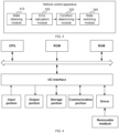
- FIG. 4 is a schematic structural diagram of a computer system suitable for implementing an electronic device according to an embodiment of this application. It should be noted that the computer system of the electronic device shown in FIG. 4 is merely an example, and should not impose any limitation on a function and a use range of the embodiments of this application.
- the computer system includes a central processing unit (Central Processing Unit, CPU).
- the CPU may perform various proper actions and processing based on a program stored in a read-only memory (Read-Only Memory, ROM) or a program loaded from a storage portion to a random access memory (Random Access Memory, RAM), for example, perform the method provided in the foregoing embodiments.
- the RAM further stores various programs and data required for a system operation.
- the CPU, the ROM, and the RAM are connected to each other through a bus.
- An input/output (Input/Output, I/O) interface is also connected to the bus.
- the following parts are connected to the I/O interface: an input portion including a keyboard, a mouse, and the like; an output portion including a cathode ray tube (Cathode Ray Tube, CRT), a liquid crystal display (Liquid Crystal Display, LCD), a speaker, and the like; the storage portion including a hard disk, and the like; and a communication portion including a network interface card such as a LAN (Local Area Network, local area network) card or a modem.
- the communication portion performs communication processing via a network such as the Internet.
- a driver is also connected to the I/O interface according to a requirement.
- a removable medium such as a magnetic disk, an optical disc, a magneto-optical disc, or a semiconductor memory is mounted on the driver according to a requirement, so that a computer program read from the removable medium is installed into the storage portion based on a requirement.
- a process described above with reference to the flowchart may be implemented as a computer software program.
- a computer program product is included.
- the computer program product includes a computer program carried on a computer-readable medium, and the computer program includes a computer program used to perform the vehicle control method shown in FIG. 2 .
- the computer program may be downloaded and installed from a network through the communication portion, and/or installed from the removable medium.
- CPU central processing unit
- the computer-readable medium described in the embodiments of this application may be a computer-readable signal medium, a computer-readable storage medium, or any combination thereof.
- the computer-readable storage medium may be, for example, an electrical system, apparatus, or device, a magnetic system, apparatus, or device, an optical system, apparatus, or device, an electromagnetic system, apparatus, or device, an infrared system, apparatus, or device, or a semiconductor system, apparatus, or device, or any combination thereof.
- a more specific example of the computer-readable storage medium may include but is not limited to an electrical connection having one or more wires, a portable computer disk, a hard disk, a random access memory (RAM), a read-only memory (ROM), an erasable programmable read-only memory (Erasable Programmable Read Only Memory, EPROM), a flash memory, an optical fiber, a portable compact disk read-only memory (Compact Disc Read-Only Memory, CD-ROM), an optical storage device, a magnetic storage device, or any proper combination thereof.
- the computer-readable signal medium may include a data signal propagated in a baseband or as a part of a carrier, and carries a computer-readable computer program.
- the propagated data signal may be in a plurality of forms, including but not limited to an electromagnetic signal, an optical signal, or any suitable combination thereof.
- the computer-readable signal medium may alternatively be any computer-readable medium other than a computer-readable storage medium, and the computer-readable medium may send, propagate, or transmit a program used by or in combination with an instruction execution system, apparatus, or device.
- the computer program included in the computer-readable medium may be transmitted by using any proper medium, including but not limited to a wireless medium or a wired medium, or any proper combination thereof.
- each block in the flowcharts or block diagrams may represent a module, a program segment, or a part of code, and the module, the program segment, or the part of code includes one or more executable instructions for implementing a specified logical function.
- a function marked in the block may also occur in a sequence different from that marked in the accompanying drawings. For example, two consecutively represented blocks may be actually executed substantially in parallel, and may sometimes be executed in a reverse order, depending on a function involved.
- each block in the block diagrams or the flowcharts and a combination of blocks in the block diagrams or the flowcharts may be implemented by using a dedicated hardware-based system designed to perform a specified function or operation, or may be implemented by using a combination of dedicated hardware and computer instructions.
- the units involved in the embodiments of this application may be implemented by using software, or may be implemented by using hardware, and the units described may also be disposed in a processor. Names of these units do not constitute a limitation on the units in a specified case.
- the computer-readable storage medium stores a computer program, and when the computer program is executed by a processor of a computer, the computer is enabled to perform the foregoing vehicle control method.
- the computer-readable storage medium may be included in the electronic device described in the foregoing embodiments, or may exist separately, and is not assembled into the electronic device.
- the computer program product or the computer program includes computer instructions, and the computer instructions are stored in a computer-readable storage medium.
- a processor of a computer device reads the computer instructions from the computer-readable storage medium, and the processor executes the computer instructions, to enable the computer device to perform the vehicle control method provided in the foregoing embodiments.
- An embodiment of this application further provides a vehicle according to the present invention.
- the vehicle is controlled by using the vehicle control method shown in FIG. 2 .
Landscapes
- Engineering & Computer Science (AREA)
- Power Engineering (AREA)
- Transportation (AREA)
- Mechanical Engineering (AREA)
- Life Sciences & Earth Sciences (AREA)
- Sustainable Development (AREA)
- Sustainable Energy (AREA)
- Electric Propulsion And Braking For Vehicles (AREA)
- Control Of Transmission Device (AREA)
- Vehicle Body Suspensions (AREA)
Applications Claiming Priority (2)
| Application Number | Priority Date | Filing Date | Title |
|---|---|---|---|
| CN202211522370.2A CN115782617B (zh) | 2022-11-30 | 2022-11-30 | 车辆控制方法、装置、设备、介质、车辆及产品 |
| PCT/CN2023/121335 WO2024114067A1 (zh) | 2022-11-30 | 2023-09-26 | 车辆控制方法、装置、设备、介质、车辆及产品 |
Publications (2)
| Publication Number | Publication Date |
|---|---|
| EP4556296A1 true EP4556296A1 (de) | 2025-05-21 |
| EP4556296A4 EP4556296A4 (de) | 2025-12-10 |
Family
ID=85443925
Family Applications (1)
| Application Number | Title | Priority Date | Filing Date |
|---|---|---|---|
| EP23896224.5A Pending EP4556296A4 (de) | 2022-11-30 | 2023-09-26 | Fahrzeugsteuerungsverfahren und -vorrichtung sowie vorrichtung, medium, fahrzeug und produkt |
Country Status (3)
| Country | Link |
|---|---|
| EP (1) | EP4556296A4 (de) |
| CN (1) | CN115782617B (de) |
| WO (1) | WO2024114067A1 (de) |
Families Citing this family (2)
| Publication number | Priority date | Publication date | Assignee | Title |
|---|---|---|---|---|
| CN115782617B (zh) * | 2022-11-30 | 2025-07-15 | 深蓝汽车科技有限公司 | 车辆控制方法、装置、设备、介质、车辆及产品 |
| CN120821186B (zh) * | 2025-09-18 | 2025-12-02 | 上海易咖智车科技有限公司 | 车速闭环控制方法、系统、车辆及存储介质 |
Family Cites Families (15)
| Publication number | Priority date | Publication date | Assignee | Title |
|---|---|---|---|---|
| CN101550986B (zh) | 2009-05-02 | 2011-06-22 | 罗清 | 主动控制型电动扭振减振器及其实现方法 |
| CN102448756B (zh) * | 2009-05-27 | 2014-12-10 | 丰田自动车株式会社 | 混合动力车辆的控制装置 |
| JP5573456B2 (ja) * | 2010-07-23 | 2014-08-20 | 日産自動車株式会社 | 電動車両の制振制御装置および電動車両の制振制御方法 |
| DE102013104513A1 (de) * | 2012-05-04 | 2013-11-07 | Ford Global Technologies, Llc | Verfahren und Systeme zum Verringern von Zahnradspielgeräuschen |
| CN104670213A (zh) * | 2013-11-27 | 2015-06-03 | 上海汽车集团股份有限公司 | 一种消除汽车传动系统间隙引起抖动的扭矩控制方法 |
| US9873422B2 (en) * | 2016-05-16 | 2018-01-23 | Ford Global Technologies, Llc | Driveline lash control method during driver tip-in/out |
| CN107472076B (zh) * | 2016-06-24 | 2019-11-22 | 宝沃汽车(中国)有限公司 | 车辆的扭矩控制方法、装置及车辆 |
| CN108052760B (zh) * | 2017-12-25 | 2021-03-16 | 长安大学 | 一种齿轮副非线性动力学计算方法 |
| CN110406389B (zh) * | 2018-04-28 | 2021-04-06 | 广州汽车集团股份有限公司 | 车辆驾驶平顺性的控制方法、装置、计算机设备和介质 |
| CN112746875B (zh) | 2019-10-31 | 2022-08-19 | 中国航发商用航空发动机有限责任公司 | 航空发动机转子轴系复杂振动的主动控制系统、方法 |
| CN113370573B (zh) * | 2020-03-10 | 2023-01-20 | 山东省科学院激光研究所 | 一种伺服压力机的机械传动系统间隙冲击抑制系统及方法 |
| CN112960001A (zh) * | 2021-04-19 | 2021-06-15 | 北京七鑫易维信息技术有限公司 | 驾驶模式的切换方法、装置、车辆及存储介质 |
| CN113263923A (zh) * | 2021-07-05 | 2021-08-17 | 珠海格力电器股份有限公司 | 电动车辆的电机控制方法、装置、存储介质及整车控制器 |
| CN115071439B (zh) * | 2022-06-14 | 2025-06-06 | 一汽解放汽车有限公司 | 车辆上装控制方法、装置、计算机设备和存储介质 |
| CN115782617B (zh) * | 2022-11-30 | 2025-07-15 | 深蓝汽车科技有限公司 | 车辆控制方法、装置、设备、介质、车辆及产品 |
-
2022
- 2022-11-30 CN CN202211522370.2A patent/CN115782617B/zh active Active
-
2023
- 2023-09-26 EP EP23896224.5A patent/EP4556296A4/de active Pending
- 2023-09-26 WO PCT/CN2023/121335 patent/WO2024114067A1/zh not_active Ceased
Also Published As
| Publication number | Publication date |
|---|---|
| WO2024114067A1 (zh) | 2024-06-06 |
| CN115782617A (zh) | 2023-03-14 |
| CN115782617B (zh) | 2025-07-15 |
| EP4556296A4 (de) | 2025-12-10 |
| WO2024114067A9 (zh) | 2025-03-06 |
Similar Documents
| Publication | Publication Date | Title |
|---|---|---|
| EP4556296A1 (de) | Fahrzeugsteuerungsverfahren und -vorrichtung sowie vorrichtung, medium, fahrzeug und produkt | |
| CN110126807B (zh) | 车速控制方法、车速控制系统和车辆 | |
| CN113968146B (zh) | 一种电动车辆限速控制方法、装置和系统 | |
| CN113655794A (zh) | 基于鲁棒模型预测控制的多车协同控制方法 | |
| Wang et al. | Vibration control method for an electric city bus driven by a dual motor coaxial series drive system based on model predictive control | |
| CN114987555B (zh) | 自动驾驶纵向异常状态确定方法、装置、电子设备及介质 | |
| US20090235274A1 (en) | Apparatus and method for task count control | |
| US12508921B2 (en) | Control device for electric vehicle | |
| CN119058420B (zh) | 车辆扭矩控制系统、车辆扭矩控制方法及车辆 | |
| CN119239315B (zh) | 新能源商用车的主动靠齿方法、装置、设备及存储介质 | |
| EP4708113A1 (de) | Selbstlernendes verfahren und system für optimale ökonomische kurve einer serienstromerzeugung für ein hybridfahrzeugmodell | |
| CN116678631B (zh) | 一种车辆驾驶性优化方法、装置、存储介质、电子设备 | |
| CN115743136B (zh) | 控制方法及装置、设备、计算机可读存储介质 | |
| CN115848378B (zh) | 参数更新方法、车辆控制方法、装置、设备及介质 | |
| CN116911045A (zh) | 减速器齿轮参数优化方法、装置、设备及存储介质 | |
| CN118478745A (zh) | 一种电平衡修正方法 | |
| CN115972913B (zh) | 基于打滑状态的扭振控制方法、装置、设备及介质 | |
| CN115520175A (zh) | 控制方法及装置、设备、计算机可读存储介质 | |
| CN113035403A (zh) | 一种核电厂异常工况下的自动控制方法 | |
| CN116241648B (zh) | 一种智能驾驶矿车的换挡规律确定方法及相关设备 | |
| CN115839408B (zh) | 一种档位控制方法及装置、电子设备、存储介质 | |
| CN116238342B (zh) | 一种电动汽车过渡扭矩输出方法、装置、设备、存储介质及加速踏板模式切换方法 | |
| CN116252633A (zh) | 一种基于电机的差速限额方法、装置、设备及存储介质 | |
| CN115626157B (zh) | 碰撞避让方法、装置、存储介质及计算机设备 | |
| CN119898204A (zh) | 一种制动能量回收方法、装置、设备及介质 |
Legal Events
| Date | Code | Title | Description |
|---|---|---|---|
| STAA | Information on the status of an ep patent application or granted ep patent |
Free format text: STATUS: THE INTERNATIONAL PUBLICATION HAS BEEN MADE |
|
| PUAI | Public reference made under article 153(3) epc to a published international application that has entered the european phase |
Free format text: ORIGINAL CODE: 0009012 |
|
| STAA | Information on the status of an ep patent application or granted ep patent |
Free format text: STATUS: REQUEST FOR EXAMINATION WAS MADE |
|
| 17P | Request for examination filed |
Effective date: 20250217 |
|
| AK | Designated contracting states |
Kind code of ref document: A1 Designated state(s): AL AT BE BG CH CY CZ DE DK EE ES FI FR GB GR HR HU IE IS IT LI LT LU LV MC ME MK MT NL NO PL PT RO RS SE SI SK SM TR |
|
| A4 | Supplementary search report drawn up and despatched |
Effective date: 20251112 |
|
| RIC1 | Information provided on ipc code assigned before grant |
Ipc: B60L 15/20 20060101AFI20251106BHEP Ipc: B60L 7/18 20060101ALI20251106BHEP |
|
| DAV | Request for validation of the european patent (deleted) | ||
| DAX | Request for extension of the european patent (deleted) | ||
| GRAP | Despatch of communication of intention to grant a patent |
Free format text: ORIGINAL CODE: EPIDOSNIGR1 |
|
| STAA | Information on the status of an ep patent application or granted ep patent |
Free format text: STATUS: GRANT OF PATENT IS INTENDED |