EP4556137A1 - Granular metal production device - Google Patents
Granular metal production device Download PDFInfo
- Publication number
- EP4556137A1 EP4556137A1 EP23856941.2A EP23856941A EP4556137A1 EP 4556137 A1 EP4556137 A1 EP 4556137A1 EP 23856941 A EP23856941 A EP 23856941A EP 4556137 A1 EP4556137 A1 EP 4556137A1
- Authority
- EP
- European Patent Office
- Prior art keywords
- flow path
- hot iron
- granular
- iron
- flow
- Prior art date
- Legal status (The legal status is an assumption and is not a legal conclusion. Google has not performed a legal analysis and makes no representation as to the accuracy of the status listed.)
- Pending
Links
Images


Classifications
-
- B—PERFORMING OPERATIONS; TRANSPORTING
- B22—CASTING; POWDER METALLURGY
- B22D—CASTING OF METALS; CASTING OF OTHER SUBSTANCES BY THE SAME PROCESSES OR DEVICES
- B22D41/00—Casting melt-holding vessels, e.g. ladles, tundishes, cups or the like
-
- B—PERFORMING OPERATIONS; TRANSPORTING
- B22—CASTING; POWDER METALLURGY
- B22D—CASTING OF METALS; CASTING OF OTHER SUBSTANCES BY THE SAME PROCESSES OR DEVICES
- B22D23/00—Casting processes not provided for in groups B22D1/00 - B22D21/00
-
- B—PERFORMING OPERATIONS; TRANSPORTING
- B22—CASTING; POWDER METALLURGY
- B22D—CASTING OF METALS; CASTING OF OTHER SUBSTANCES BY THE SAME PROCESSES OR DEVICES
- B22D25/00—Special casting characterised by the nature of the product
- B22D25/02—Special casting characterised by the nature of the product by its peculiarity of shape; of works of art
-
- B—PERFORMING OPERATIONS; TRANSPORTING
- B22—CASTING; POWDER METALLURGY
- B22D—CASTING OF METALS; CASTING OF OTHER SUBSTANCES BY THE SAME PROCESSES OR DEVICES
- B22D5/00—Machines or plants for pig or like casting
-
- B—PERFORMING OPERATIONS; TRANSPORTING
- B22—CASTING; POWDER METALLURGY
- B22F—WORKING METALLIC POWDER; MANUFACTURE OF ARTICLES FROM METALLIC POWDER; MAKING METALLIC POWDER; APPARATUS OR DEVICES SPECIALLY ADAPTED FOR METALLIC POWDER
- B22F9/00—Making metallic powder or suspensions thereof
- B22F9/02—Making metallic powder or suspensions thereof using physical processes
- B22F9/06—Making metallic powder or suspensions thereof using physical processes starting from liquid material
- B22F9/08—Making metallic powder or suspensions thereof using physical processes starting from liquid material by casting, e.g. through sieves or in water, by atomising or spraying
-
- B—PERFORMING OPERATIONS; TRANSPORTING
- B22—CASTING; POWDER METALLURGY
- B22F—WORKING METALLIC POWDER; MANUFACTURE OF ARTICLES FROM METALLIC POWDER; MAKING METALLIC POWDER; APPARATUS OR DEVICES SPECIALLY ADAPTED FOR METALLIC POWDER
- B22F9/00—Making metallic powder or suspensions thereof
- B22F9/02—Making metallic powder or suspensions thereof using physical processes
- B22F9/06—Making metallic powder or suspensions thereof using physical processes starting from liquid material
- B22F9/08—Making metallic powder or suspensions thereof using physical processes starting from liquid material by casting, e.g. through sieves or in water, by atomising or spraying
- B22F9/10—Making metallic powder or suspensions thereof using physical processes starting from liquid material by casting, e.g. through sieves or in water, by atomising or spraying using centrifugal force
-
- B—PERFORMING OPERATIONS; TRANSPORTING
- B22—CASTING; POWDER METALLURGY
- B22F—WORKING METALLIC POWDER; MANUFACTURE OF ARTICLES FROM METALLIC POWDER; MAKING METALLIC POWDER; APPARATUS OR DEVICES SPECIALLY ADAPTED FOR METALLIC POWDER
- B22F9/00—Making metallic powder or suspensions thereof
- B22F9/02—Making metallic powder or suspensions thereof using physical processes
- B22F9/06—Making metallic powder or suspensions thereof using physical processes starting from liquid material
- B22F9/08—Making metallic powder or suspensions thereof using physical processes starting from liquid material by casting, e.g. through sieves or in water, by atomising or spraying
- B22F9/082—Making metallic powder or suspensions thereof using physical processes starting from liquid material by casting, e.g. through sieves or in water, by atomising or spraying atomising using a fluid
- B22F2009/086—Cooling after atomisation
- B22F2009/0872—Cooling after atomisation by water
-
- B—PERFORMING OPERATIONS; TRANSPORTING
- B22—CASTING; POWDER METALLURGY
- B22F—WORKING METALLIC POWDER; MANUFACTURE OF ARTICLES FROM METALLIC POWDER; MAKING METALLIC POWDER; APPARATUS OR DEVICES SPECIALLY ADAPTED FOR METALLIC POWDER
- B22F9/00—Making metallic powder or suspensions thereof
- B22F9/02—Making metallic powder or suspensions thereof using physical processes
- B22F9/06—Making metallic powder or suspensions thereof using physical processes starting from liquid material
- B22F9/08—Making metallic powder or suspensions thereof using physical processes starting from liquid material by casting, e.g. through sieves or in water, by atomising or spraying
- B22F9/082—Making metallic powder or suspensions thereof using physical processes starting from liquid material by casting, e.g. through sieves or in water, by atomising or spraying atomising using a fluid
- B22F2009/0896—Making metallic powder or suspensions thereof using physical processes starting from liquid material by casting, e.g. through sieves or in water, by atomising or spraying atomising using a fluid particle transport, separation: process and apparatus
Definitions
- the present invention relates to a granular metal production device, and particularly relates to a granular metal production device for producing granular metal by allowing molten metal to flow down and collide with a collision structure for granulation, followed by solidification.
- Such a granular metal production device includes one described in PTL 1 below, for example.
- hot iron produced in a blast furnace or the like is poured into a container (trough), and thereafter the hot iron at a predetermined flow rate overflowing from a predetermined place in the container is allowed to flow down by free fall.
- the flow of the hot iron is allowed to collide with the inclined surface of a first inclined platen inclined at a predetermined angle, and is partially scattered into the air and granulated.
- the hot iron flowing down along the inclined surface of the first inclined platen without scattering is allowed to collide with the inclined surface of a second inclined platen arranged under the first inclined platen and inclined at a predetermined angle, and is scattered into the air and granulated.
- the granulated hot iron falls into cooling water retained in a lower water tank, followed by cooling and solidification, to be collected as granular iron which is granular metal by a conveyor.
- PTL 1 describes that the number of the inclined platens to be provided may be three or more.
- the hot iron becomes granular iron with a particle size equal to or smaller than a predetermined particle size, and particularly that the granulated hot iron does not stick each other with cooling water contained thereinside as described below.
- the granular metal production device described in PTL 1 it is required to maintain a large flow-down velocity of the hot iron to collide with the inclined platen, particularly the inclined platen on the last stage, and this requires that the distance in the height direction between the inclined platens is increased.
- the entire granular metal production device becomes excessively large in the height direction.
- the height of the granular metal production device is regulated, it becomes difficult to make the hot iron (molten metal) into granular iron (granular metal) with a particle size equal to or smaller than a predetermined particle size.
- the present invention has been made in view of the above-described problem. It is an object of the present invention to provide a granular metal production device capable of making molten metal into granular metal with a particle size equal to or smaller than a predetermined particle size even when the height is regulated.
- the present invention provides the following (1) to (6).
- the molten metal in the first flow path collides with the step at an inlet of the second flow path formed by an opening area difference, causing a rapid velocity fluctuation.
- This generates a velocity distribution in the cross section of the molten metal flowing down from the second flow path, and the velocity distribution enables reliable granulation of the molten metal colliding with the collision structure to be scattered.
- the molten metal can be made into granular metal with a particle size equal to or smaller than a predetermined particle size.
- FIG. 1 is a schematic overall configuration view illustrating one embodiment of a granular metal production device.
- the granular metal production device of this embodiment is a device for producing granular iron as granular metal from hot iron, which is molten metal, as with PTL 1 above.
- the hot iron is treated as molten metal and the granular iron is treated as granular metal.
- the granular iron production device is a facility for mass-producing granular iron with a particle size of about 10 mm, for example.
- the hot iron conveyed with a torpedo car 1 is poured into a hot iron trough 2, and then allowed to flow into a receiving container 3 to be temporarily retained in the receiving container 3.
- the hot iron stored in the receiving container 3 is allowed to flow straightly downward at a predetermined flow rate from a discharge port 4 provided in a bottom part 3a of the receiving container 3.
- the hot iron flowing down from the receiving container 3 freely falls to collide with the upper surface of a collision structure 5 arranged below.
- the upper surface of the collision structure 5 is flat, and therefore the hot iron is scattered from the upper surface of the collision structure 5 toward the outside of the outer periphery. This scattering granulates the hot iron, and thereafter the resultant hot iron is allowed to fall into cooling water in a water tank 6 arranged below.
- the granular hot iron falling into the cooling water is cooled and solidified to be granular iron, which is granular metal.
- a granular iron chute 7 for accumulating the solidified granular iron is provided under the scattering range of the granular hot iron inside the water tank 6, a granular iron chute 7 for accumulating the solidified granular iron is provided.
- the granular iron falling into the water from an upper end opening part of the granular iron chute 7 is accumulated in a chute center part along a funnel-shaped inclined surface formed by the conical surface of a truncated cone, and then allowed to fall again into the cooling water from a lower end opening part. Then, the granular iron falls into the water on the upper surface of a net belt of a net conveyor 8 to be conveyed by the net conveyor 8 to the upper outside of the water tank 6.
- the temperature of the cooling water increases due to the high-temperature hot iron. Therefore, the device is configured to take in low-temperature cooling water. In addition, the
- the granular iron is easy to dissolve, and therefore easy to use.
- the method is increasingly spreading which includes bringing the hot iron allowed to flow down from the receiving container 3 into collision with the collision structure 5 to scatter the hot iron in the form of granules for granulation, and allowing the resultant hot iron to fall into the cooling water for cooling and solidification.
- the temperature of the hot iron when the hot iron falls into the cooling water is as high as about 1200°C to 1500°C.
- PTL 1 above installs two or more stages of inclined plates, which are the collision structures 5 for the flowing-down hot iron, so that the hot iron can be granulated to have a particle size equal to or smaller than a predetermined particle size.
- the device when a multi-stage inclined platen is provided, the device (facility) increases in size in the height direction as described above. This has a disadvantage of increasing the facility cost or the construction cost in addition to the problem arising when the height is restricted.
- the inclined platen, which is the collision structure 5 is exposed to the high-temperature hot iron, and therefore requires regular maintenance. An increase in the number of the inclined platens also increases the frequency of replacement of the collision structure 5, resulting in an increased maintenance cost.
- the hot iron colliding with the collision structure 5 to be scattered can be granulated to have a particle size equal to or smaller than a predetermined particle size by devising the discharge port 4 of the hot iron provided in the bottom part 3a of the receiving container 3.
- FIG. 2 is a detailed view of the discharge port 4 of the hot iron provided in the bottom part 3a of the receiving container 3.
- the receiving container 3 of this embodiment is structured such that the inside of an iron shell in an upwardly open box shape is covered with firebricks as with a tundish used in continuous casting, and is provided with the discharge port 4 of the hot iron in the bottom part 3a.
- the discharge port 4 is configured such that an upper first flow path 9 provided in a firebrick portion of the bottom part 3a of the receiving container 3 and a lower second flow path 10 provided in an iron shell portion are vertically arranged to be continuous with each other. Accordingly, the hot iron in the receiving container 3 passes through the discharge port 4 from the first flow path 9 in the firebrick portion to the second flow path 10 in the iron shell portion, and flows down under the container 3.
- the cross-sectional shapes of both the first flow path 9 and the second flow path 10 are circular shapes.
- the cross-sectional area of the second flow path 10 located below is smaller than the cross-sectional area of the first flow path 9 located above, and the lower end of the first flow path 9 and a step 11 are provided at an upper end opening position of the second flow path 10.
- both the first flow path 9 and the second flow path 10 have cylindrical shapes, and therefore, when the cross-sectional area of the second flow path 10 located below is smaller than the cross-sectional area of the first flow path 9, the lower end of the first flow path 9 and the step 11 are formed at the upper end opening position of the second flow path 10.
- the step 11 projecting from the lower end of the first flow path 9 is formed at the upper end opening position of the second flow path 10 as described later.
- the upper end opening area of the second flow path 10 located below may be smaller than the lower end opening area of the first flow path 9 located above.
- the present inventors have variously investigated requirements for granulating the hot iron to have a particle size equal to or smaller than a predetermined particle size after colliding with the collision structure 5 without requiring a significant flow-down distance of the hot iron before colliding with the collision structure 5.
- the collision structure 5 is constituted by a refractory substance and is arranged such that the upper surface (collision surface) of the collision structure 5 is located directly vertically below the discharge port 4 of the hot iron.
- the hot iron colliding with the upper surface of the collision structure 5 is scattered so as to spread outward from the outer periphery of the collision structure 5.
- the collision surface of the collision structure 5 desirably has a circular shape.
- the collision surface of the collision structure 5 is desirably flat (horizontal surface).
- the hot iron is granulated outside an umbrella-shaped continuously spreading region. Therefore, when the umbrella-shaped spread (region) is large, the hot iron is connected in a film shape, making it difficult to granulate the hot iron. More specifically, the present inventors have found that, when the umbrella-shaped spread (region) can be reduced, the granulation of the hot iron is facilitated, and thus the particle size can also be reduced.
- the present inventors have found that the more stable the flow of the hot iron before colliding with the collision structure 5, the larger the umbrella-shaped spread after the collision, and accordingly, to reduce the umbrella-shaped spread, a velocity distribution may be imparted to the flow velocity in the cross section of the flow of the hot iron flowing down from the discharge port 4.
- a uniform velocity distribution is likely to be maintained even when the hot iron collides with the collision structure, and the hot iron after colliding with the collision structure spreads in a film shape, forming a large umbrella and forming relatively large particles in many cases.
- the present inventors have focused on providing the velocity distribution by emphasizing the inflow of the hot iron from the surroundings near the outlet of the discharge port 4 in place of providing an obstacle at the outlet of the discharge port 4.
- an element generating the velocity distribution in the cross section may be added to the flow of the hot iron before the hot iron flows down from the receiving container 3.
- the hot iron collides with the step 11 at the opening upper end position of the second flow path 10, and the hot iron flows into a center part from the peripheral wall side of the first flow path 9.
- FIG. 3 schematically illustrates the flow velocities with and without the velocity distribution in the cross section of the flow of the hot iron to simulate the scattering state of the hot iron after the collision.
- the radial position in the cross section is expressed by a ratio of the radial position to the diameter of the cross section.
- the two-dot chain line in the figure indicates a state in which the flow velocity in the cross section of the flow of the hot iron was constant at an average velocity Ve, i.e., no velocity distribution.
- the solid line in the figure indicates that the flow velocity in the center part of the cross section of the flow of the hot iron before the collision was about twice the average velocity Ve, while the flow velocity in a peripheral part of the cross section was set to almost zero. More specifically, the latter is the flow velocity of the hot iron by the discharge port 4 in this embodiment, and the former is the flow velocity by a conventional discharge port 4 of the hot iron with no step.
- the scattering state of the hot iron after the collision in accordance with the flow velocity in the cross section of the flowing-down hot iron was simulated as described below.
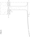
- the discharge port 4 contains only the second flow path 10, for example, and the discharge port 4 of the hot iron has no step, i.e., there is no velocity change in the flow velocity in the cross section of the flowing-down hot iron, a hot iron film spreads in an umbrella shape, and the hot iron on the outside of the umbrella-shaped spread tends to connect, so that the hot iron is difficult to granulate to have a particle size equal to or smaller than a predetermined particle size (see FIG. 5 ).
- the discharge port 4 of the hot iron has the step 11
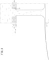
- the umbrella-shaped hot iron film becomes small, and the hot iron is granulated to have a uniform particle size on the outside of the umbrella-shaped spread, and the particle size is small (see FIG. 4 ).
- the hot iron colliding with the upper surface (collision surface) of the collision structure 5 partially collides with each other.
- the particle size of the granulated hot iron is uniformly small, the granulated hot iron is uniformly cooled and solidified after falling into the cooling water, and therefore the resultant hot iron is difficult to stick each other in the cooling water. Accordingly, the particle size of the granular iron after cooling can be made small, and there is no risk of a steam explosion.
- the cross sections of the first flow path 9 and the second flow path 10 are set to circular shapes, but the cross sections of the flow paths 9, 10 may have shapes other than the circular shapes.
- the size of the flow path when the cross section has a circular shape can be expressed by the diameter, whereas the size of the flow path when the cross section has a non-circular shape can be expressed by the hydraulic diameter.
- the step 11 formed with the lower end of the first flow path 9 at the opening upper end position of the second flow path 10 is desirably even on the upper end opening peripheral edge of the second flow path 10.
- the hydraulic diameter of the upper end cross-section of the second flow path 10 is required to be 80% or less of the hydraulic diameter of the lower end cross-section of the first flow path 9.
- the hydraulic diameter of the upper end cross-section of the second flow path 10 is set to 10% or more of the hydraulic diameter of the lower end cross-section of the first flow path 9.
- a peripheral edge portion of the first flow path 9 may be chamfered at the upper end opening position of the first flow path 9.
- the flow path length of the second flow path 10 is smaller than the flow path length of the first flow path 9, and the flow path length of the second flow path 10 is preferably set to 50% or less of the flow path length of the first flow path 9. Supposing that the second flow path 10 is a pipeline, when the pipeline length increases, a boundary layer to be generated on the pipeline inner wall develops, and the velocity distribution of the hot iron in the cross section generated in the step portion is disregarded.
- the flow path length of the second flow path 10 may be set to a smaller one of 50% or less of the first flow path 9 or 20 times or less the hydraulic diameter of the second flow path 10.
- the flow path length of the second flow path 10 is 0, the effect of the rapid velocity change of the hot iron by the step 11 cannot be obtained, and therefore the flow path length of the second flow path 10 is desirably larger than 1% of the hydraulic diameter of the second flow path 10.
- the size of the hydraulic diameter of the second flow path 10 was set to 76% of the hydraulic diameter of the first flow path 9, and the flow path length of the second flow path 10 was set to 7% in size of the hydraulic diameter of the second flow path 10.
- Fluent (2021R1) of Ansys, Inc. which is fluid simulation application software, was used.
- the physical properties of a fluid simulating hot iron were set as follows: the fluid density was 8000 kg/m 3 , the fluid viscosity was 0.055 Pa ⁇ s, and the fluid surface tension was 0.9 N/m. Air was assumed as the gas, and the physical property values provided in the Fluent were used.
- the calculation was performed by unsteady calculation, and the multi-phase flow was calculated using the volume of fluid (VOF) method without considering a turbulence model.
- An inflow condition from the receiving container 3 into the discharge port 4 was set such that a fluid (hot iron) flows in at a uniform velocity of 4 m/s.
- FIG. 5 illustrates the scattering state of the hot iron after the collision by a conventional granular iron production device with no step in the middle of the discharge port 4
- FIG. 4 illustrates the scattering state of the hot iron after the collision by the granular iron production device in the embodiment with the step 11 reduced in diameter at the upper end opening position of the lower second flow path 10.
- the umbrella of the film of the hot iron scattering after the collision is large, and, as a result, the granulated hot iron is connected on the outside of the umbrella of the hot iron film.
- the umbrella of the hot iron film is small indicates that the hot iron in the scattering state is in a state of being easily separated from each other, and particles of the hot iron formed on the outside of the umbrella have a uniform and small particle size.
- the granular iron having a uniformly small particle size is rapidly and individually cooled and solidified in the cooling water, and therefore the granular iron is difficult to stick each other.
- the hot iron in the first flow path 9 collides with the step 11, which is formed by an opening area difference, at the inlet of the second flow path 10, causing a rapid velocity fluctuation.
- This generates the velocity distribution of the flow velocity in the cross section of the hot iron flowing down from the second flow path 10.
- the velocity distribution enables reliable granulation of the hot iron colliding with the collision structure 5 to be scattered.
- the hot iron can be made into the granular iron with a particle size equal to or smaller than a predetermined particle size.
- both the first flow path 9 and the second flow path 10 are formed inside the bottom part 3a of the receiving container 3, the flow-down distance of the hot iron from the receiving container 3 to the collision structure 5 can be shortened, making it possible to reduce the dimension in the height direction of the device.
- the step 11 is evenly provided on the upper end opening peripheral edge of the second flow path 10, making it possible to increase the amount of the hot iron flowing into the center part from a peripheral wall part of the first flow path 9 and increase the velocity distribution of the flow velocity in the flow-down cross-section of the hot iron.
- the hot iron after the collision with the collision structure 5 and cooling can be reliably made into granular iron with a particle size equal to or smaller than a predetermined particle size.
- the velocity distribution of the flow velocity can be reliably generated in the cross section of the hot iron flowing down from the second flow path 10.
- the flow path length of the second flow path 10 By setting the flow path length of the second flow path 10 to be smaller than the flow path length of the first flow path 9, preferably 50% or less of the flow path length of the first flow path 9, the velocity distribution of the flow velocity in the cross section of the hot iron flowing down from the second flow path 10 can be maintained.
- the granular metal production device according to the embodiment is described above, but the present invention is not limited to the configurations described in the above-described embodiment, and can be variously altered within the scope of the gist of the present invention.
- these flow paths 9, 10 may be formed in a region where the hot iron flows down from the inside of the receiving container 3 toward the collision structure 5.
- the above-described embodiment gives a detailed description only about the case of producing granular iron from hot iron.
- the granular metal production device of the present invention is similarly applicable to any metal insofar as granular metal is produced by allowing molten metal stored in the container 3 to flow down and collide with the collision structure 5 for granulation, followed by solidification.
Landscapes
- Engineering & Computer Science (AREA)
- Mechanical Engineering (AREA)
- Manufacture Of Metal Powder And Suspensions Thereof (AREA)
Abstract
Description
- The present invention relates to a granular metal production device, and particularly relates to a granular metal production device for producing granular metal by allowing molten metal to flow down and collide with a collision structure for granulation, followed by solidification.
- Such a granular metal production device includes one described in PTL 1 below, for example. In the granular metal production device, hot iron produced in a blast furnace or the like is poured into a container (trough), and thereafter the hot iron at a predetermined flow rate overflowing from a predetermined place in the container is allowed to flow down by free fall. The flow of the hot iron is allowed to collide with the inclined surface of a first inclined platen inclined at a predetermined angle, and is partially scattered into the air and granulated. The hot iron flowing down along the inclined surface of the first inclined platen without scattering is allowed to collide with the inclined surface of a second inclined platen arranged under the first inclined platen and inclined at a predetermined angle, and is scattered into the air and granulated. The granulated hot iron falls into cooling water retained in a lower water tank, followed by cooling and solidification, to be collected as granular iron which is granular metal by a conveyor. PTL 1 describes that the number of the inclined platens to be provided may be three or more.
- PTL 1:
JPH 5-154607 A - In such granular iron production, it is essential that the hot iron becomes granular iron with a particle size equal to or smaller than a predetermined particle size, and particularly that the granulated hot iron does not stick each other with cooling water contained thereinside as described below. To achieve this condition with the granular metal production device described in PTL 1, it is required to maintain a large flow-down velocity of the hot iron to collide with the inclined platen, particularly the inclined platen on the last stage, and this requires that the distance in the height direction between the inclined platens is increased. However, when the distance in the height direction between the inclined platen is secured, there is such a problem that the entire granular metal production device becomes excessively large in the height direction. Conversely, when the height of the granular metal production device is regulated, it becomes difficult to make the hot iron (molten metal) into granular iron (granular metal) with a particle size equal to or smaller than a predetermined particle size.
- The present invention has been made in view of the above-described problem. It is an object of the present invention to provide a granular metal production device capable of making molten metal into granular metal with a particle size equal to or smaller than a predetermined particle size even when the height is regulated.
- To achieve the above-described object, the present invention provides the following (1) to (6).
- (1) A granular metal production device according to the present invention for producing granular metal by allowing molten metal stored inside a container to flow down from the container and collide with a collision structure for granulation, followed by solidification, including: a first flow path and a second flow path configured to allow the molten metal to flow down from the container toward the collision structure and provided at upper and lower positions in a continuous state, in which the upper end opening area of the second flow path located below is smaller than the lower end opening area of the first flow path located above, and the lower end of the first flow path and a step are provided at an upper end opening position of the second flow path.
- (2) The granular metal production device according to the present invention, in which both the first flow path and the second flow path are provided inside a bottom part of the container in the granular metal production device according to (1) above.
- (3) The granular metal production device according to the present invention, in which the step is evenly provided on the upper end opening peripheral edge of the second flow path in the granular metal production device according to (1) or (2) above.
- (4) The granular metal production device according to the present invention, in which the hydraulic diameter of an upper end cross-section of the second flow path is 10% to 80% in size of the hydraulic diameter of a lower end cross-section of the first flow path in the granular metal production device according to any one of (1) to (3) above.
- (5) The granular metal production device according to the present invention, in which the second flow path has a flow path length smaller than a flow path length of the first flow path in the granular metal production device according to any one of (1) to (4) above.
- (6) The granular metal production device according to the present invention, in which the flow path length of the second flow path is 50% or less of the flow path length of the first flow path in the granular metal production device according to (5) above.
- According to the granular metal production device of the present invention, when the molten metal flows from the upper first flow path into the lower second flow path, the molten metal in the first flow path collides with the step at an inlet of the second flow path formed by an opening area difference, causing a rapid velocity fluctuation. This generates a velocity distribution in the cross section of the molten metal flowing down from the second flow path, and the velocity distribution enables reliable granulation of the molten metal colliding with the collision structure to be scattered. As a result, even when the height of the device is restricted, the molten metal can be made into granular metal with a particle size equal to or smaller than a predetermined particle size.
-
-
FIG. 1 is a schematic overall configuration view illustrating one embodiment of a granular metal production device according to the present invention; -
FIG. 2 is a detailed view of a discharge port of hot iron provided in a bottom part of a container inFIG. 1 ; -
FIG. 3 is an explanatory view of a velocity distribution of molten metal flowing down from a second flow path inFIG. 2 ; -
FIG. 4 is an explanatory view of the action of the molten metal flowing down from a first flow path and the second flow path inFIG. 2 ; and -
FIG. 5 is an explanatory view of the action of molten metal flowing down from a conventional flow path. - Hereinafter, one embodiment of a granular metal production device according to the present invention is described in detail with reference to the drawings. The embodiment described below exemplifies devices or methods for embodying the technical idea of the present invention, and the technical idea of the present invention does not specify the materials, shapes, structures, arrangement, and the like of constituent components to the materials, shapes, structures, arrangement, and the like of the embodiment described below. The drawings are schematic. Therefore, it should be noted that the relation between the thickness and the planar dimension, the ratio, and the like are different from the actual relation, ratio, and the like. The drawings include portions different in mutual dimensional relationships and ratios.
-
FIG. 1 is a schematic overall configuration view illustrating one embodiment of a granular metal production device. The granular metal production device of this embodiment is a device for producing granular iron as granular metal from hot iron, which is molten metal, as with PTL 1 above. Hereinafter, the hot iron is treated as molten metal and the granular iron is treated as granular metal. The granular iron production device is a facility for mass-producing granular iron with a particle size of about 10 mm, for example. For example, the hot iron conveyed with a torpedo car 1 is poured into ahot iron trough 2, and then allowed to flow into a receivingcontainer 3 to be temporarily retained in the receivingcontainer 3. The hot iron stored in thereceiving container 3 is allowed to flow straightly downward at a predetermined flow rate from adischarge port 4 provided in abottom part 3a of thereceiving container 3. The hot iron flowing down from thereceiving container 3 freely falls to collide with the upper surface of acollision structure 5 arranged below. The upper surface of thecollision structure 5 is flat, and therefore the hot iron is scattered from the upper surface of thecollision structure 5 toward the outside of the outer periphery. This scattering granulates the hot iron, and thereafter the resultant hot iron is allowed to fall into cooling water in awater tank 6 arranged below. - The granular hot iron falling into the cooling water is cooled and solidified to be granular iron, which is granular metal. Under the scattering range of the granular hot iron inside the
water tank 6, a granular iron chute 7 for accumulating the solidified granular iron is provided. The granular iron falling into the water from an upper end opening part of the granular iron chute 7 is accumulated in a chute center part along a funnel-shaped inclined surface formed by the conical surface of a truncated cone, and then allowed to fall again into the cooling water from a lower end opening part. Then, the granular iron falls into the water on the upper surface of a net belt of anet conveyor 8 to be conveyed by thenet conveyor 8 to the upper outside of thewater tank 6. The temperature of the cooling water increases due to the high-temperature hot iron. Therefore, the device is configured to take in low-temperature cooling water. In addition, the device can be configured to cool the cooling water or both the configurations can also be used in combination. - As described in PTL 1 above, the granular iron is easy to dissolve, and therefore easy to use. Various granular iron production methods have been developed, but, as described above, the method is increasingly spreading which includes bringing the hot iron allowed to flow down from the receiving
container 3 into collision with thecollision structure 5 to scatter the hot iron in the form of granules for granulation, and allowing the resultant hot iron to fall into the cooling water for cooling and solidification. The temperature of the hot iron when the hot iron falls into the cooling water is as high as about 1200°C to 1500°C. When the hot iron of such a high-temperature (overheated) comes into contact with the water, the heat of the hot iron is removed as the water evaporates, but a film boiling state occurs in which a vapor film is formed between the outer surface of the hot iron and the cooling water. In the film boiling, evaporation occurs in the vapor film due to heat transferred through the vapor film from the heated surface. The film boiling has a low cooling capacity, and, for example, merely has a heat transfer coefficient of about one-hundredth of that of nucleate boiling, in which no vapor film is generated. Therefore, when the film boiling continues for a long time, the granulated hot iron cannot be sufficiently cooled, and the granulated hot iron sticks each other in the cooling water in some cases. When the granular iron sticks each other (combined), the number of clumps of the granular iron of a size difficult to convey increases, making it difficult to convey the granular iron. Further, when the cooling water is contained inside the combined granular iron, there is such a risk that the cooling water evaporates and causes a steam explosion. - The best way to avoid such a problem is to ensure that the granulated hot iron is cooled and solidified as it is without combined to be granulated to have a particle size equal to or smaller than a predetermined particle size when the hot iron falls into the cooling water. Thus, PTL 1 above installs two or more stages of inclined plates, which are the
collision structures 5 for the flowing-down hot iron, so that the hot iron can be granulated to have a particle size equal to or smaller than a predetermined particle size. However, when a multi-stage inclined platen is provided, the device (facility) increases in size in the height direction as described above. This has a disadvantage of increasing the facility cost or the construction cost in addition to the problem arising when the height is restricted. Further, the inclined platen, which is thecollision structure 5, is exposed to the high-temperature hot iron, and therefore requires regular maintenance. An increase in the number of the inclined platens also increases the frequency of replacement of thecollision structure 5, resulting in an increased maintenance cost. - In the granular iron production device of this embodiment, the hot iron colliding with the
collision structure 5 to be scattered can be granulated to have a particle size equal to or smaller than a predetermined particle size by devising thedischarge port 4 of the hot iron provided in thebottom part 3a of the receivingcontainer 3.FIG. 2 is a detailed view of thedischarge port 4 of the hot iron provided in thebottom part 3a of the receivingcontainer 3. The receivingcontainer 3 of this embodiment is structured such that the inside of an iron shell in an upwardly open box shape is covered with firebricks as with a tundish used in continuous casting, and is provided with thedischarge port 4 of the hot iron in thebottom part 3a. Thedischarge port 4 is configured such that an upperfirst flow path 9 provided in a firebrick portion of thebottom part 3a of the receivingcontainer 3 and a lowersecond flow path 10 provided in an iron shell portion are vertically arranged to be continuous with each other. Accordingly, the hot iron in the receivingcontainer 3 passes through thedischarge port 4 from thefirst flow path 9 in the firebrick portion to thesecond flow path 10 in the iron shell portion, and flows down under thecontainer 3. The cross-sectional shapes of both thefirst flow path 9 and thesecond flow path 10 are circular shapes. - In this embodiment, as is clear from
FIG. 2 , the cross-sectional area of thesecond flow path 10 located below is smaller than the cross-sectional area of thefirst flow path 9 located above, and the lower end of thefirst flow path 9 and astep 11 are provided at an upper end opening position of thesecond flow path 10. In this embodiment, both thefirst flow path 9 and thesecond flow path 10 have cylindrical shapes, and therefore, when the cross-sectional area of thesecond flow path 10 located below is smaller than the cross-sectional area of thefirst flow path 9, the lower end of thefirst flow path 9 and thestep 11 are formed at the upper end opening position of thesecond flow path 10. What is important about thedischarge port 4 of the hot iron of this embodiment is that thestep 11 projecting from the lower end of thefirst flow path 9 is formed at the upper end opening position of thesecond flow path 10 as described later. For the formation of thestep 11, the upper end opening area of thesecond flow path 10 located below may be smaller than the lower end opening area of thefirst flow path 9 located above. - The present inventors have variously investigated requirements for granulating the hot iron to have a particle size equal to or smaller than a predetermined particle size after colliding with the
collision structure 5 without requiring a significant flow-down distance of the hot iron before colliding with thecollision structure 5. Thecollision structure 5 is constituted by a refractory substance and is arranged such that the upper surface (collision surface) of thecollision structure 5 is located directly vertically below thedischarge port 4 of the hot iron. The hot iron colliding with the upper surface of thecollision structure 5 is scattered so as to spread outward from the outer periphery of thecollision structure 5. To make the spread of the scattering hot iron even over the entire outer periphery of thecollision structure 5, the collision surface of thecollision structure 5 desirably has a circular shape. Similarly, to stabilize the spread of the scattering hot iron, the collision surface of thecollision structure 5 is desirably flat (horizontal surface). - The hot iron scattering radially outward from the circular and flat upper surface (collision surface) of the
collision structure 5 spreads in a spherical shape like an umbrella (seeFIGS. 4 ,5 ). The hot iron is granulated outside an umbrella-shaped continuously spreading region. Therefore, when the umbrella-shaped spread (region) is large, the hot iron is connected in a film shape, making it difficult to granulate the hot iron. More specifically, the present inventors have found that, when the umbrella-shaped spread (region) can be reduced, the granulation of the hot iron is facilitated, and thus the particle size can also be reduced. Further, the present inventors have found that the more stable the flow of the hot iron before colliding with thecollision structure 5, the larger the umbrella-shaped spread after the collision, and accordingly, to reduce the umbrella-shaped spread, a velocity distribution may be imparted to the flow velocity in the cross section of the flow of the hot iron flowing down from thedischarge port 4. When the flow velocity is uniform in the cross section of the flow of the hot iron, a uniform velocity distribution is likely to be maintained even when the hot iron collides with the collision structure, and the hot iron after colliding with the collision structure spreads in a film shape, forming a large umbrella and forming relatively large particles in many cases. - To impart the velocity distribution to the flow velocity in the cross section of the flow of the hot iron as described above, it is supposed to provide an obstacle at an outlet of the
discharge port 4, for example. More specifically, by providing an obstacle at the outlet of thedischarge port 4, the velocity near the obstacle decreases, making it possible to impart the velocity distribution to the flow velocity in the cross section of the flow of the hot iron. However, a nearly solid substance (slag) referred to as slag sometimes flows in the hot iron. Therefore, it is not practical to provide an obstacle at the outlet of thedischarge port 4 because there is a risk that the outlet of thedischarge port 4 is clogged with the slag, so that the flow is hindered or thedischarge port 4 is blocked. - Thus, the present inventors have focused on providing the velocity distribution by emphasizing the inflow of the hot iron from the surroundings near the outlet of the
discharge port 4 in place of providing an obstacle at the outlet of thedischarge port 4. To obtain the velocity distribution of the flow velocity in the cross section of the flow of the hot iron, an element generating the velocity distribution in the cross section may be added to the flow of the hot iron before the hot iron flows down from the receivingcontainer 3. In this embodiment, when the hot iron flows from the upperfirst flow path 9 into the lowersecond flow path 10, the hot iron collides with thestep 11 at the opening upper end position of thesecond flow path 10, and the hot iron flows into a center part from the peripheral wall side of thefirst flow path 9. As described above, when thestep 11 reduced in diameter is provided in the middle of the flow path of a fluid, stagnation occurs in the outermost portion of thestep 11, and the fluid is concentrated so as to flow into the center part from the peripheral wall side inside thestep 11. As a result, the velocity distribution in which the flow velocity in the center part of the cross section is larger than the flow velocity in the peripheral wall is generated in thesecond flow path 10. -
FIG. 3 schematically illustrates the flow velocities with and without the velocity distribution in the cross section of the flow of the hot iron to simulate the scattering state of the hot iron after the collision. The radial position in the cross section is expressed by a ratio of the radial position to the diameter of the cross section. The two-dot chain line in the figure indicates a state in which the flow velocity in the cross section of the flow of the hot iron was constant at an average velocity Ve, i.e., no velocity distribution. The solid line in the figure indicates that the flow velocity in the center part of the cross section of the flow of the hot iron before the collision was about twice the average velocity Ve, while the flow velocity in a peripheral part of the cross section was set to almost zero. More specifically, the latter is the flow velocity of the hot iron by thedischarge port 4 in this embodiment, and the former is the flow velocity by aconventional discharge port 4 of the hot iron with no step. - The scattering state of the hot iron after the collision in accordance with the flow velocity in the cross section of the flowing-down hot iron was simulated as described below. When the
discharge port 4 contains only thesecond flow path 10, for example, and thedischarge port 4 of the hot iron has no step, i.e., there is no velocity change in the flow velocity in the cross section of the flowing-down hot iron, a hot iron film spreads in an umbrella shape, and the hot iron on the outside of the umbrella-shaped spread tends to connect, so that the hot iron is difficult to granulate to have a particle size equal to or smaller than a predetermined particle size (seeFIG. 5 ). On the other hand, when thedischarge port 4 of the hot iron has thestep 11, i.e., when there is a velocity change in the flow velocity of the hot iron in the flow-down cross-section, the umbrella-shaped hot iron film becomes small, and the hot iron is granulated to have a uniform particle size on the outside of the umbrella-shaped spread, and the particle size is small (seeFIG. 4 ). This is considered to be because the hot iron colliding with the upper surface (collision surface) of thecollision structure 5 partially collides with each other. When the particle size of the granulated hot iron is uniformly small, the granulated hot iron is uniformly cooled and solidified after falling into the cooling water, and therefore the resultant hot iron is difficult to stick each other in the cooling water. Accordingly, the particle size of the granular iron after cooling can be made small, and there is no risk of a steam explosion. - In this embodiment, the cross sections of the
first flow path 9 and thesecond flow path 10 are set to circular shapes, but the cross sections of theflow paths 
- The
step 11 formed with the lower end of thefirst flow path 9 at the opening upper end position of thesecond flow path 10 is desirably even on the upper end opening peripheral edge of thesecond flow path 10. To cause a rapid velocity fluctuation in the hot iron flowing in thefirst flow path 9 in a step portion and generate the velocity distribution of the hot iron in the cross section of thesecond flow path 10, the hydraulic diameter of the upper end cross-section of thesecond flow path 10 is required to be 80% or less of the hydraulic diameter of the lower end cross-section of thefirst flow path 9. On the other hand, when the upper end opening area of thesecond flow path 10 is excessively small, the velocity distribution of the hot iron is difficult to generate in the cross section of thesecond flow path 10, and therefore the hydraulic diameter of the upper end cross-section of thesecond flow path 10 is set to 10% or more of the hydraulic diameter of the lower end cross-section of thefirst flow path 9. A peripheral edge portion of thefirst flow path 9 may be chamfered at the upper end opening position of thefirst flow path 9. - When the flow path length of the
second flow path 10 is excessively large, there is such a risk that the flow velocity of the hot iron is stabilized while the hot iron is passing through thesecond flow path 10, and a sufficient velocity distribution cannot be obtained in the cross section of the hot iron flowing down from thedischarge port 4. Therefore, the flow path length of thesecond flow path 10 is smaller than the flow path length of thefirst flow path 9, and the flow path length of thesecond flow path 10 is preferably set to 50% or less of the flow path length of thefirst flow path 9. Supposing that thesecond flow path 10 is a pipeline, when the pipeline length increases, a boundary layer to be generated on the pipeline inner wall develops, and the velocity distribution of the hot iron in the cross section generated in the step portion is disregarded. This phenomenon is supposed to occur when the pipeline length is about 20 times the pipeline diameter, and therefore the flow path length of thesecond flow path 10 is desirably smaller than 20 times the hydraulic diameter of thesecond flow path 10. The flow path length of thesecond flow path 10 may be set to a smaller one of 50% or less of thefirst flow path 9 or 20 times or less the hydraulic diameter of thesecond flow path 10. When the flow path length of thesecond flow path 10 is 0, the effect of the rapid velocity change of the hot iron by thestep 11 cannot be obtained, and therefore the flow path length of thesecond flow path 10 is desirably larger than 1% of the hydraulic diameter of thesecond flow path 10. - The following description gives an example of a hot iron discharge port model used in the simulation above. In this model, the size of the hydraulic diameter of the
second flow path 10 was set to 76% of the hydraulic diameter of thefirst flow path 9, and the flow path length of thesecond flow path 10 was set to 7% in size of the hydraulic diameter of thesecond flow path 10. For the simulation, Fluent (2021R1) of Ansys, Inc., which is fluid simulation application software, was used. The physical properties of a fluid simulating hot iron were set as follows: the fluid density was 8000 kg/m3, the fluid viscosity was 0.055 Pa·s, and the fluid surface tension was 0.9 N/m. Air was assumed as the gas, and the physical property values provided in the Fluent were used. As calculation conditions, the calculation was performed by unsteady calculation, and the multi-phase flow was calculated using the volume of fluid (VOF) method without considering a turbulence model. An inflow condition from the receivingcontainer 3 into thedischarge port 4 was set such that a fluid (hot iron) flows in at a uniform velocity of 4 m/s. - As described above,
FIG. 5 illustrates the scattering state of the hot iron after the collision by a conventional granular iron production device with no step in the middle of thedischarge port 4 andFIG. 4 illustrates the scattering state of the hot iron after the collision by the granular iron production device in the embodiment with thestep 11 reduced in diameter at the upper end opening position of the lowersecond flow path 10. As is clear fromFIG. 5 , in the conventional granular iron production device in which the velocity distribution of the flow velocity is absent or small in the cross section of the flow of the hot iron before the collision, the umbrella of the film of the hot iron scattering after the collision is large, and, as a result, the granulated hot iron is connected on the outside of the umbrella of the hot iron film. In the state in which the granulated hot iron is connected as described above, it is difficult to obtain granular iron with a particle size equal to or smaller than a predetermined particle size and it takes time to cool the connected granulated iron in the cooling water, and therefore the granular iron is likely to stick each other. On the other hand, as illustrated inFIG. 4 , in the granular iron production device in the embodiment in which the velocity distribution of the flow velocity is large in the cross section of the flow of the hot iron before the collision, the umbrella of the film of the hot iron scattering after the collision is small. The fact that the umbrella of the hot iron film is small indicates that the hot iron in the scattering state is in a state of being easily separated from each other, and particles of the hot iron formed on the outside of the umbrella have a uniform and small particle size. The granular iron having a uniformly small particle size is rapidly and individually cooled and solidified in the cooling water, and therefore the granular iron is difficult to stick each other. - Thus, in the granular iron production device of this embodiment, when the hot iron flows from the upper
first flow path 9 into the lowersecond flow path 10, the hot iron in thefirst flow path 9 collides with thestep 11, which is formed by an opening area difference, at the inlet of thesecond flow path 10, causing a rapid velocity fluctuation. This generates the velocity distribution of the flow velocity in the cross section of the hot iron flowing down from thesecond flow path 10. The velocity distribution enables reliable granulation of the hot iron colliding with thecollision structure 5 to be scattered. As a result, even when the height of the device is restricted, the hot iron can be made into the granular iron with a particle size equal to or smaller than a predetermined particle size. - Due to the fact that both the
first flow path 9 and thesecond flow path 10 are formed inside thebottom part 3a of the receivingcontainer 3, the flow-down distance of the hot iron from the receivingcontainer 3 to thecollision structure 5 can be shortened, making it possible to reduce the dimension in the height direction of the device. - The
step 11 is evenly provided on the upper end opening peripheral edge of thesecond flow path 10, making it possible to increase the amount of the hot iron flowing into the center part from a peripheral wall part of thefirst flow path 9 and increase the velocity distribution of the flow velocity in the flow-down cross-section of the hot iron. As a result, the hot iron after the collision with thecollision structure 5 and cooling can be reliably made into granular iron with a particle size equal to or smaller than a predetermined particle size. - By setting the hydraulic diameter of the upper end cross-section of the
second flow path 10 to 10% to 80% in size of the hydraulic diameter of the lower end cross-section of thefirst flow path 9, the velocity distribution of the flow velocity can be reliably generated in the cross section of the hot iron flowing down from thesecond flow path 10. - By setting the flow path length of the
second flow path 10 to be smaller than the flow path length of thefirst flow path 9, preferably 50% or less of the flow path length of thefirst flow path 9, the velocity distribution of the flow velocity in the cross section of the hot iron flowing down from thesecond flow path 10 can be maintained. - The granular metal production device according to the embodiment is described above, but the present invention is not limited to the configurations described in the above-described embodiment, and can be variously altered within the scope of the gist of the present invention. For example, although the
first flow path 9 and thesecond flow path 10 are formed inside thebottom part 3a of the receivingcontainer 3 in the above-described embodiment, theseflow paths container 3 toward thecollision structure 5. By forming thefirst flow path 9 and thesecond flow path 10 inside thebottom part 3a of the receivingcontainer 3, the distance in the height direction from the receivingcontainer 3 to thecollision structure 5 can be shortened, making the device compact. - The above-described embodiment gives a detailed description only about the case of producing granular iron from hot iron. However, the granular metal production device of the present invention is similarly applicable to any metal insofar as granular metal is produced by allowing molten metal stored in the
container 3 to flow down and collide with thecollision structure 5 for granulation, followed by solidification. -
- 3: receiving container (container)
- 3a: bottom part
- 4: discharge port
- 5: collision structure
- 6: water tank
- 9: first flow path
- 10: second flow path
- 11: step
Claims (6)
- A granular metal production device for producing granular metal by allowing molten metal stored inside a container to flow down from the container and collide with a collision structure for granulation, followed by solidification,
the granular metal production device comprising:a first flow path and a second flow path configured to allow the molten metal to flow down from the container toward the collision structure and provided at upper and lower positions in a continuous state, whereinan upper end opening area of the second flow path located below is smaller than a lower end opening area of the first flow path located above, and a lower end of the first flow path and a step are provided at an upper end opening position of the second flow path. - The granular metal production device according to claim 1, wherein both the first flow path and the second flow path are provided inside a bottom part of the container.
- The granular metal production device according to claim 1 or 2, wherein the step is evenly provided on an upper end opening peripheral edge of the second flow path.
- The granular metal production device according to any one of claims 1 to 3, wherein a hydraulic diameter of an upper end cross-section of the second flow path is 10% to 80% in size of a hydraulic diameter of a lower end cross-section of the first flow path.
- The granular metal production device according to any one of claims 1 to 4, wherein the second flow path has a flow path length smaller than a flow path length of the first flow path.
- The granular metal production device according to claim 5, wherein the flow path length of the second flow path is 50% or less of the flow path length of the first flow path.
Applications Claiming Priority (2)
| Application Number | Priority Date | Filing Date | Title |
|---|---|---|---|
| JP2022132486 | 2022-08-23 | ||
| PCT/JP2023/022236 WO2024042824A1 (en) | 2022-08-23 | 2023-06-15 | Granular metal production device |
Publications (2)
| Publication Number | Publication Date |
|---|---|
| EP4556137A1 true EP4556137A1 (en) | 2025-05-21 |
| EP4556137A4 EP4556137A4 (en) | 2025-12-24 |
Family
ID=89451925
Family Applications (1)
| Application Number | Title | Priority Date | Filing Date |
|---|---|---|---|
| EP23856941.2A Pending EP4556137A4 (en) | 2022-08-23 | 2023-06-15 | DEVICE FOR THE PRODUCTION OF GRAIN METAL |
Country Status (4)
| Country | Link |
|---|---|
| EP (1) | EP4556137A4 (en) |
| JP (1) | JP7409576B1 (en) |
| KR (1) | KR20250041024A (en) |
| CN (1) | CN119730975A (en) |
Family Cites Families (4)
| Publication number | Priority date | Publication date | Assignee | Title |
|---|---|---|---|---|
| JPH0776362B2 (en) * | 1987-03-11 | 1995-08-16 | 三菱マテリアル株式会社 | Metal grain manufacturing equipment |
| JPH05154607A (en) | 1991-12-03 | 1993-06-22 | Nippon Steel Corp | Production of granulated pig iron |
| JP6717356B2 (en) * | 2018-03-27 | 2020-07-01 | 日立金属株式会社 | Method for producing metal particles |
| JP7247934B2 (en) * | 2020-03-31 | 2023-03-29 | Jfeスチール株式会社 | Granulated iron manufacturing equipment |
-
2023
- 2023-06-15 CN CN202380059801.2A patent/CN119730975A/en active Pending
- 2023-06-15 KR KR1020257005755A patent/KR20250041024A/en active Pending
- 2023-06-15 EP EP23856941.2A patent/EP4556137A4/en active Pending
- 2023-06-15 JP JP2023553672A patent/JP7409576B1/en active Active
Also Published As
| Publication number | Publication date |
|---|---|
| JPWO2024042824A1 (en) | 2024-02-29 |
| KR20250041024A (en) | 2025-03-25 |
| EP4556137A4 (en) | 2025-12-24 |
| CN119730975A (en) | 2025-03-28 |
| JP7409576B1 (en) | 2024-01-09 |
Similar Documents
| Publication | Publication Date | Title |
|---|---|---|
| JP7247934B2 (en) | Granulated iron manufacturing equipment | |
| JP7251498B2 (en) | Granulated iron manufacturing equipment | |
| JP6674473B2 (en) | Nozzle and tundish apparatus for granulating molten material | |
| JP7444147B2 (en) | Granulated iron production equipment and granulated iron manufacturing method | |
| Chang et al. | Modeling on dry centrifugal granulation process of molten blast furnace slag | |
| CN105612016B (en) | The granulation of melted material | |
| JP7468820B1 (en) | Granulated iron manufacturing apparatus and granulated iron manufacturing method | |
| NO319998B1 (en) | Method and apparatus for making metal chunks | |
| JP7409576B1 (en) | Granular metal manufacturing equipment | |
| WO2024042824A1 (en) | Granular metal production device | |
| Woo et al. | Numerical probing of a low velocity concurrent pilot scale spray drying tower for mono-disperse particle production–unusual characteristics and possible improvements | |
| CS216663B2 (en) | Facility for making the metal components | |
| US7638076B2 (en) | Method and system for pelletizing sulfur | |
| JP7380634B2 (en) | Granular pig iron production equipment and method for cooling granular pig iron | |
| JP7435540B2 (en) | Granular pig iron manufacturing equipment and granular pig iron manufacturing method | |
| JP7708337B1 (en) | Granulated iron manufacturing equipment | |
| CN110267734A (en) | Apparatus and method for producing granular solid urea | |
| RU2075997C1 (en) | Method and apparatus for material granulation | |
| JP2002146412A (en) | Gutter for molten slag | |
| TWI624446B (en) | Rotating-cup slag granulation syatem and control method therefor | |
| CA3182146A1 (en) | Method and device for dry granulation | |
| Thai et al. | Application of a transient heat conduction model for design of urea prilling tower | |
| PL102276B1 (en) | A DEVICE FOR PRODUCING GRANULES | |
| UA113141U (en) | Vortex pelletizer | |
| EA033854B1 (en) | Device for dry granulation of liquid slag |
Legal Events
| Date | Code | Title | Description |
|---|---|---|---|
| STAA | Information on the status of an ep patent application or granted ep patent |
Free format text: STATUS: THE INTERNATIONAL PUBLICATION HAS BEEN MADE |
|
| PUAI | Public reference made under article 153(3) epc to a published international application that has entered the european phase |
Free format text: ORIGINAL CODE: 0009012 |
|
| STAA | Information on the status of an ep patent application or granted ep patent |
Free format text: STATUS: REQUEST FOR EXAMINATION WAS MADE |
|
| 17P | Request for examination filed |
Effective date: 20250213 |
|
| AK | Designated contracting states |
Kind code of ref document: A1 Designated state(s): AL AT BE BG CH CY CZ DE DK EE ES FI FR GB GR HR HU IE IS IT LI LT LU LV MC ME MK MT NL NO PL PT RO RS SE SI SK SM TR |
|
| DAV | Request for validation of the european patent (deleted) | ||
| DAX | Request for extension of the european patent (deleted) | ||
| A4 | Supplementary search report drawn up and despatched |
Effective date: 20251124 |
|
| RIC1 | Information provided on ipc code assigned before grant |
Ipc: B22D 5/00 20060101AFI20251118BHEP Ipc: B22D 23/00 20060101ALI20251118BHEP Ipc: B22D 25/02 20060101ALI20251118BHEP Ipc: B22F 9/08 20060101ALI20251118BHEP Ipc: B22D 41/00 20060101ALI20251118BHEP |