EP4556134A1 - Method for manufacturing press-molded article - Google Patents
Method for manufacturing press-molded article Download PDFInfo
- Publication number
- EP4556134A1 EP4556134A1 EP23862731.9A EP23862731A EP4556134A1 EP 4556134 A1 EP4556134 A1 EP 4556134A1 EP 23862731 A EP23862731 A EP 23862731A EP 4556134 A1 EP4556134 A1 EP 4556134A1
- Authority
- EP
- European Patent Office
- Prior art keywords
- press
- forming
- top portion
- punch
- side wall
- Prior art date
- Legal status (The legal status is an assumption and is not a legal conclusion. Google has not performed a legal analysis and makes no representation as to the accuracy of the status listed.)
- Pending
Links
Images




Classifications
-
- B—PERFORMING OPERATIONS; TRANSPORTING
- B21—MECHANICAL METAL-WORKING WITHOUT ESSENTIALLY REMOVING MATERIAL; PUNCHING METAL
- B21D—WORKING OR PROCESSING OF SHEET METAL OR METAL TUBES, RODS OR PROFILES WITHOUT ESSENTIALLY REMOVING MATERIAL; PUNCHING METAL
- B21D22/00—Shaping without cutting, by stamping, spinning, or deep-drawing
- B21D22/20—Deep-drawing
- B21D22/26—Deep-drawing for making peculiarly, e.g. irregularly, shaped articles
-
- B—PERFORMING OPERATIONS; TRANSPORTING
- B21—MECHANICAL METAL-WORKING WITHOUT ESSENTIALLY REMOVING MATERIAL; PUNCHING METAL
- B21D—WORKING OR PROCESSING OF SHEET METAL OR METAL TUBES, RODS OR PROFILES WITHOUT ESSENTIALLY REMOVING MATERIAL; PUNCHING METAL
- B21D53/00—Making other particular articles
- B21D53/88—Making other particular articles other parts for vehicles, e.g. cowlings, mudguards
-
- B—PERFORMING OPERATIONS; TRANSPORTING
- B21—MECHANICAL METAL-WORKING WITHOUT ESSENTIALLY REMOVING MATERIAL; PUNCHING METAL
- B21D—WORKING OR PROCESSING OF SHEET METAL OR METAL TUBES, RODS OR PROFILES WITHOUT ESSENTIALLY REMOVING MATERIAL; PUNCHING METAL
- B21D22/00—Shaping without cutting, by stamping, spinning, or deep-drawing
- B21D22/20—Deep-drawing
- B21D22/206—Deep-drawing articles from a strip in several steps, the articles being coherent with the strip during the operation
-
- B—PERFORMING OPERATIONS; TRANSPORTING
- B21—MECHANICAL METAL-WORKING WITHOUT ESSENTIALLY REMOVING MATERIAL; PUNCHING METAL
- B21D—WORKING OR PROCESSING OF SHEET METAL OR METAL TUBES, RODS OR PROFILES WITHOUT ESSENTIALLY REMOVING MATERIAL; PUNCHING METAL
- B21D24/00—Special deep-drawing arrangements in, or in connection with, presses
- B21D24/005—Multi-stage presses
-
- B—PERFORMING OPERATIONS; TRANSPORTING
- B21—MECHANICAL METAL-WORKING WITHOUT ESSENTIALLY REMOVING MATERIAL; PUNCHING METAL
- B21D—WORKING OR PROCESSING OF SHEET METAL OR METAL TUBES, RODS OR PROFILES WITHOUT ESSENTIALLY REMOVING MATERIAL; PUNCHING METAL
- B21D5/00—Bending sheet metal along straight lines, e.g. to form simple curves
- B21D5/01—Bending sheet metal along straight lines, e.g. to form simple curves between rams and anvils or abutments
-
- B—PERFORMING OPERATIONS; TRANSPORTING
- B21—MECHANICAL METAL-WORKING WITHOUT ESSENTIALLY REMOVING MATERIAL; PUNCHING METAL
- B21D—WORKING OR PROCESSING OF SHEET METAL OR METAL TUBES, RODS OR PROFILES WITHOUT ESSENTIALLY REMOVING MATERIAL; PUNCHING METAL
- B21D37/00—Tools as parts of machines covered by this subclass
- B21D37/08—Dies with different parts for several steps in a process
Definitions
- the present invention relates to a method of manufacturing a press-formed part including at least a top portion having a concave curved portion that curves concavely in a side view and a side wall portion continuous from the top portion via a punch shoulder R portion.
- punch shoulder R portion refers to a portion of a formed part
- punch shoulder refers to a portion of a mold.
- Examples of vehicle parts or partial structures thereof include a press-formed part having at least a top portion and a side wall portion continuous from the top portion via a punch shoulder R portion, in which the top portion has a curved portion that curves concavely in a side view.
- a press-formed part having at least a top portion and a side wall portion continuous from the top portion via a punch shoulder R portion, in which the top portion has a curved portion that curves concavely in a side view.
- the distal end portion of the side wall portion continuous with the punch shoulder R portion at the bottom of the concave curved portion of the top portion and in the vicinity of the bottom undergo stretch flange deformation. Therefore, the sheet thickness is reduced at the portion, and cracking is likely to occur.
- the sheet thickness of the punch shoulder R portion at the bottom of the concave curved portion of the top portion and in the vicinity of the bottom increases, and buckling (wrinkles, folds) is likely to occur.
- Patent Literature 1 conventionally proposes a countermeasure against cracking due to stretch flange deformation of a press-formed part including a flat top portion having a concave outer peripheral edge in a top view and a side wall portion continuous from the top portion along the concave outer peripheral edge.
- Patent Literature 1 WO 2014/097745 A
- the press-forming method described in Patent Literature 1 is targeted to a press-formed part in which the top portion is flat and has a concave outer peripheral edge in a top view.
- the present invention is targeted to a press-formed part including at least a top portion having a concave curved portion that curves concavely in a side view and a side wall portion continuous from the top portion via a punch shoulder R portion.
- the press-formed part targeted by Patent Literature 1 and the press-formed part targeted by the present invention have different shapes.
- Patent Literature 1 Even if the press-forming method of Patent Literature 1 is applied to the press-formed part targeted by the invention of the present application, it is not possible to prevent cracking of a portion of the press-formed part having undergone the stretch flange deformation, or wrinkles and folds at the punch shoulder R portion.
- the present invention has been made in view of the above problems, and an object of the present invention is to provide a method of manufacturing a press-formed part including at least a top portion having a concave curved portion that curves concavely in a side view and a side wall portion continuous from the top portion via a punch shoulder R portion, the method capable of suppressing cracking of the press-formed part, or preventing wrinkles and folds.
- a method of manufacturing a press-formed part according to the present invention is the method of manufacturing the press-formed part including at least a top portion having a concave curved portion that curves concavely in a side view and a side wall portion continuous from the top portion via a punch shoulder R portion.
- the method includes: a first forming step of press-forming an intermediate forming part including an intermediate top portion curved in the same direction as the top portion, a step-shaped portion formed of a step which is continuous with a ridge line portion formed at a portion corresponding to the punch shoulder R portion, and an outer surface portion that extends outward continuously from the step-shaped portion and curves in the same direction as the intermediate top portion; and a second forming step of press-forming the intermediate forming part into the press-formed part.
- a radius of curvature of the ridge line portion of the intermediate forming part may be greater than or equal to a radius of curvature of the punch shoulder R portion of the press-formed part.
- the method of manufacturing a press-formed part according to the present invention has an effect of preventing wrinkles and folds in the punch shoulder R portion and the vicinity thereof at the bottom of the concave curved portion of the top portion and in the vicinity of the bottom, and suppressing cracking in the distal end portion of the side wall portion continuous with the punch shoulder R portion.
- the press-formed part 1 targeted by the present invention includes at least a top portion 3 having a concave curved portion that curves concavely in a side view, and a side wall portion 7 continuous from the top portion 3 via a punch shoulder R portion 5, and an example thereof is an article having an L-shaped cross section as illustrated in FIG. 7 .
- FIG. 8 illustrates a conventional mold used when the press-formed part 1 targeted by the present invention is press-formed by one step.
- the conventional mold includes a punch 9 having a concave curved portion, a pad 11 having a concave curved portion similar to that of the punch 9, and a die 13. While the blank 15 being a metal sheet is pressed by the pad 11 and the punch 9 so that the concave curved portion of the top portion 3 is formed, the die 13 is relatively moved to form the side wall portion 7.
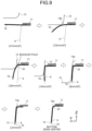
- FIG. 9 illustrates a cross section (a cross section cut in the direction of arrow A illustrated in FIG. 7 ) of the bottom of the curve in the concave curved portion of the top portion 3 of the press-formed part 1 during the press forming.
- a numerical value such as [28mmup] in FIG. 9 represents a gap in the press forming direction between a punch shoulder 33 of the punch 9 and a die jaw portion 13a (see FIG. 8 and [2mmup] of FIG. 9 ) up to the bottom dead center, in which the sheet thickness is taken into account.
- the gap between the punch shoulder 33 of the punch 9 and the die jaw portion 13a at [28mmup] is obtained by adding 28 mm to the sheet thickness of the press-formed part 1.
- the blank 15 is pressed against the punch 9 by the pad 11 at [47mmup], and a concave curved portion is formed.
- the entire blank 15 including the portion to be formed into the side wall is curved in a concave shape in the direction perpendicular to the drawing plane.
- a die shoulder 13b comes into contact with the blank 15 so that the side wall portion 7 starts to be formed. Therefore, the end of the portion corresponding to the side wall of the blank 15 is curved downward.
- the portion corresponding to the side wall is curved in a concave shape in the direction perpendicular to the drawing plane and thus has high rigidity, and is less likely to be deformed along the punch shoulder R portion 5 (ridge line) serving as a boundary between the top portion 3 and the side wall portion 7. Therefore, at [28mmup], the bottom of the concave curved portion of the blank 15 brought into contact with the die shoulder 13b of the die 13 is bent, and a buckled fold is generated.
- the portion where the buckled fold is generated is bent in the forming direction up to [19mmup] without coming into contact with the punch shoulder 33 of the punch 9.
- the portion where the buckled fold is generated is formed into the side wall portion 7 by the gap between the die 13 and the punch 9, and becomes the punch shoulder R portion 5 by coming into contact with the punch shoulder 33 of the punch 9 at the bottom dead center.
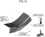
- FIG. 10 is a diagram illustrating a sheet thickness distribution at the bottom dead center obtained by subjecting a conventional press forming process to FEM analysis.
- the dotted line A-A in FIG. 10 indicates the position of the bottom of the concave curved portion similarly to FIG. 7 .
- the distal end portion of the side wall portion 7 continuous with the bottom of the concave curved portion having undergone stretch flange deformation exhibits a maximum sheet thickness decrease rate of as large as 12.3%, so that cracking is likely to occur.
- the punch shoulder R portion 5 exhibits a maximum sheet thickness increase rate of as large as 10.0%, and hence a wrinkle or fold is likely to be generated.
- the curved portion having a concave shape in a side view formed at an initial stage of press forming has high rigidity due to its shape. Therefore, when the side wall portion 7 is to be subsequently formed by the die 13, a large compressive force acts on the blank 15 to increase the sheet thickness, so that a buckled fold is generated and hence a wrinkle or fold is likely to be generated.
- the side wall portion 7 continuous with the concave curved portion expands to the left and right of the concave curved portion and undergoes stretch flange deformation, and a large tension acts on the distal end of the side wall portion 7 continuous with the bottom of the curve, so that the sheet thickness decreases and cracking is likely to occur.
- the present inventor has focused on the deformation of the blank 15 from [28mmup] to [2mmup] in FIG. 9 . That is, the present inventor has considered that if the blank 15 can be brought into contact with the punch shoulder 33 of the punch 9 at the initial stage of forming at [28mmup], the blank 15 will not suffer from a buckled fold in the forming direction without coming into contact with the punch shoulder 33 of the punch 9, and wrinkles and folds as in the conventional art can be prevented. Furthermore, the present inventor has considered that if the forming height of the side wall portion 7 at the time of forming the side wall portion 7 of the target shape can be reduced, the degree of stretch flange deformation is reduced and hence cracking is less likely to occur.
- the press forming step is divided into two steps of a first forming step and a second forming step, as illustrated in FIG. 1 .
- first forming step an intermediate forming part 19 curved in the same direction as a press-formed part 1 and having a step-shaped portion 17 is press-formed
- second forming step the intermediate forming part 19 is press-formed into the press-formed part 1 of a target shape.
- the intermediate forming part 19 includes an intermediate top portion 21 curved in the same direction as the top portion 3 of the press-formed part 1, a ridge line portion 23 formed at a portion corresponding to a punch shoulder R portion 5, and the step-shaped portion 17 formed of a step which is continuous with the ridge line portion 23.
- FIG. 2 illustrates an example in which the intermediate top portion 21 having the same shape as the top portion 3 of the press-formed part 1 is provided.
- an outer surface portion 25 which extends outward continuously with the step-shaped portion 17 and is curved in the same direction as the intermediate top portion 21 is provided.
- the outer surface portion 25 is formed into a side wall portion 7 in the second forming step.
- FIG. 2 illustrates an example in which the outer surface portion 25 is parallel to the intermediate top portion 21, but in the present invention, the outer surface portion 25 only needs to be curved in the same direction as the intermediate top portion 21, and does not need to have the same curvature as the intermediate top portion 21.
- the intermediate top portion 21 only needs to reach a curvature of the top portion 3 of the press-formed part 1 in the second forming step, and thus does not need to completely match the shape of the top portion 3 of the press-formed part 1 of the target shape.
- the first forming step and the second forming step will be described in detail with reference to FIG. 1 , taking the case where the intermediate forming part 19 has the shape illustrated in FIG. 2 as an example.
- a step-forming punch 27 and a step-forming die 29 are used, as illustrated in FIG. 1(a) .
- the intermediate forming part 19 having the intermediate top portion 21, the step-shaped portion 17, and the outer surface portion 25 is press-formed by the step-forming punch 27 and the step-forming die 29.
- the radius of curvature of the ridge line portion 23 of the intermediate forming part 19 is preferably greater than or equal to the radius of curvature of the punch shoulder R portion 5 of the press-formed part 1.
- the upper limit of the radius of curvature of the ridge line portion 23 is not particularly limited, but it is preferably up to 5 times the radius of curvature of the punch shoulder R portion 5 of the press-formed part 1 in accordance with the shape of the press-formed part 1 and the thickness of the metal sheet. This is because it allows the ridge line portion 23 to easily come into contact with the punch shoulder 33 of the punch 9 in the second forming step.
- the punch 9, the pad 11, and the die 13 for forming the press-formed part 1 of a target shape are used, as illustrated in FIG. 1(b) .
- the tools illustrated in FIG. 1(b) is similar to those illustrated in FIG. 8 as a conventional example.
- the intermediate forming part 19 is placed on the punch 9 and pressed by the pad 11, and the die 13 is relatively moved toward the punch 9 to form the outer surface portion 25 into the side wall portion 7, thereby forming the press-formed part 1 of a target shape.
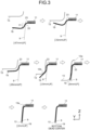
- FIG. 3 illustrates movements of the punch 9 and the die 13 in the second forming step and a deformation process of the intermediate forming part 19 in a cross section cut in the direction of the arrow A illustrated in FIG. 2 .
- a numerical value such as [28mmup] represents a gap in the press forming direction between the punch shoulder 33 and the die jaw portion 13a up to the bottom dead center, in which the sheet thickness is taken into account, similarly to the case of FIG. 9 described above. Therefore, the gap between the punch shoulder 33 and the die jaw portion 13a at [28mmup] is obtained by adding 28 mm to the sheet thickness of the press-formed part 1.
- the intermediate forming part 19 is placed on the punch 9 and pressed by the pad 11 in the second forming step.
- the ridge line portion 23 of the step-shaped portion 17 comes into contact with the punch shoulder 33 of the punch 9, as illustrated in the drawing of [47mmup]. Since the step-shaped portion 17 of the intermediate forming part 19 is along the punch shoulder 33 in this manner, the degree of deformation of the ridge line portion 23 in the subsequent forming processes is reduced, thereby suppressing the increase in the sheet thickness and thus preventing a buckled fold.
- the die shoulder 13b of the die 13 comes into contact with the bottom of the concave curved portion of the outer surface portion 25, and the entire outer surface portion 25 is bent back.
- the forming of the side wall portion 7 further proceeds through [8mmup] and [2mmup], and the forming is completed at the bottom dead center.
- the forming height of the side wall portion in the second forming step in the forming process of the side wall portion 7 corresponds to the distance from the lower portion of the step-shaped portion 17 to the end portion of the outer surface portion 25. Therefore, the forming height of the side wall portion in the second forming step is shorter than the distance from the R start position of the ridge line portion 23 of the top portion 3 to the end portion of the blank 15 as in the conventional example. Therefore, a decrease in sheet thickness due to stretch flange deformation is suppressed, and occurrence of cracking can be prevented.
- FIG. 4 is a diagram illustrating the sheet thickness distribution at the bottom dead center in the first forming step and the second forming step obtained by subjecting the press forming process of the present embodiment to FEM analysis.
- FIG. 4(a) illustrates the sheet thickness distribution at the bottom dead center in the first forming step.
- FIG. 4(b) illustrates the sheet thickness distribution at the bottom dead center in the second forming step.
- the maximum sheet thickness increase rate was 3.1% at the ridge line portion 23, and the maximum sheet thickness decrease rate was 3.7% at the outer surface portion 25, as described in FIG. 4(a) .
- the maximum sheet thickness increase rate was 3.1% at the punch shoulder R portion 5, and the maximum sheet thickness decrease rate was 10.8% at the distal end portion of the side wall portion 7, as described in FIG. 4(b) .
- the maximum sheet thickness increase rate at the punch shoulder R portion 5 was significantly reduced to 3.1% in the present embodiment from 10.0% of the conventional example. Therefore, it can be seen that wrinkles and folds at the ridge line portion 23 can be prevented. Furthermore, the maximum sheet thickness decrease rate at the distal end portion of the side wall portion 7 was reduced to 10.8% in the present embodiment from 12.3% of the conventional example. Therefore, it can be seen that cracking caused by stretch flange deformation can be suppressed.
- the die 13 used in the second forming step had the linear die shoulder 13b for forming the side wall portion 7, as illustrated in FIG. 1(b) .
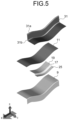
- the die used in the second forming step in the present invention may be a die 31 having a die shoulder 31b curved along the outer surface portion 25 of the intermediate forming part 19, as illustrated in FIG. 5 . With such a shape, when the outer surface portion 25 is formed into the side wall portion 7, the outer surface portion 25 can be simultaneously formed over the entire length.
- the reference numeral 31a in FIG. 5 denotes a die jaw portion.
- a press-forming analysis by FEM for confirming the effect of the present invention has been performed, which will be described below.
- a press-forming analysis was performed on the press-formed part 1 having the top portion 3 curved in a concave shape in a side view and the side wall portion 7 continuous with the top portion 3 as illustrated in FIG. 6 with use of a 980 MPa-class steel sheet having a sheet thickness of 1.4 mm so that the sheet thickness distribution was determined.
- the dimensions of respective portions of the press-formed part 1 were as described in FIG. 6 .
- the press-forming analysis was performed by changing the shape of the outer surface portion 25 of the intermediate forming part 19 ( FIG. 2 ) in addition to the press-forming analysis on the conventional example formed by one step as illustrated in FIG.
- the intermediate forming part 19 having the step-shaped portion 17 was formed first and the intermediate forming part 19 was subsequently formed into a target shape.
- the outer surface portion 25 had a concavely curved shape similarly to the top portion 3, and the height of the step-shaped portion 17 was changed in the range from 1 mm to 20 mm.
- the maximum sheet thickness increase rate at the punch shoulder R portion 5 of the target shape and the maximum sheet thickness decrease rate at the distal end portion of the side wall were reduced as compared with the conventional example No. 1.
- the maximum sheet thickness increase rate in the punch shoulder R portion 5 of the target shape was smaller than 8% at which a wrinkle was generated, and therefore the generation of wrinkles was prevented.
- the maximum sheet thickness decrease rate at the distal end portion of the side wall of the target shape was 12.0% or less, and therefore the occurrence of cracking was prevented.
- the present invention can provide a method of manufacturing a press-formed part including at least a top portion having a concave curved portion that curves concavely in a side view and a side wall portion continuous from the top portion via a punch shoulder R portion, the method capable of suppressing cracking of the press-formed part, or preventing wrinkles and folds.
Landscapes
- Engineering & Computer Science (AREA)
- Mechanical Engineering (AREA)
- Shaping Metal By Deep-Drawing, Or The Like (AREA)
- Casting Or Compression Moulding Of Plastics Or The Like (AREA)
Abstract
Description
- The present invention relates to a method of manufacturing a press-formed part including at least a top portion having a concave curved portion that curves concavely in a side view and a side wall portion continuous from the top portion via a punch shoulder R portion. In the present specification, for example, the term "punch shoulder R portion" refers to a portion of a formed part, and the term "punch shoulder" refers to a portion of a mold.
- While the vehicle body collision safety is being improved due to the tightening of the vehicle collision safety standards, it is also necessary to reduce the weight of the vehicle body for improvement in fuel consumption and electrification of vehicles due to the carbon dioxide emission control. In order to achieve both the improvement in collision safety and reduction in weight of vehicle bodies, application of high-strength steel sheet (also referred to as high-tensile steel sheet) having a tensile strength of 590 MPa or more to structural parts of vehicle bodies is in progress.
- Examples of vehicle parts or partial structures thereof include a press-formed part having at least a top portion and a side wall portion continuous from the top portion via a punch shoulder R portion, in which the top portion has a curved portion that curves concavely in a side view. When such a press-formed part is press-formed, the distal end portion of the side wall portion continuous with the punch shoulder R portion at the bottom of the concave curved portion of the top portion and in the vicinity of the bottom undergo stretch flange deformation. Therefore, the sheet thickness is reduced at the portion, and cracking is likely to occur. In addition, the sheet thickness of the punch shoulder R portion at the bottom of the concave curved portion of the top portion and in the vicinity of the bottom increases, and buckling (wrinkles, folds) is likely to occur.
- In particular, in the case of a high-tensile steel sheet, cracking of the portion having undergone the stretch flange deformation and buckling (wrinkles, folds) of the punch shoulder R portion are likely to occur due to the increase in strength, which is particularly a problem.
- In this regard,
Patent Literature 1, for example, conventionally proposes a countermeasure against cracking due to stretch flange deformation of a press-formed part including a flat top portion having a concave outer peripheral edge in a top view and a side wall portion continuous from the top portion along the concave outer peripheral edge. - Patent Literature 1:
WO 2014/097745 A - The press-forming method described in
Patent Literature 1 is targeted to a press-formed part in which the top portion is flat and has a concave outer peripheral edge in a top view. On the other hand, the present invention is targeted to a press-formed part including at least a top portion having a concave curved portion that curves concavely in a side view and a side wall portion continuous from the top portion via a punch shoulder R portion. As described above, the press-formed part targeted byPatent Literature 1 and the press-formed part targeted by the present invention have different shapes. - Therefore, even if the press-forming method of
Patent Literature 1 is applied to the press-formed part targeted by the invention of the present application, it is not possible to prevent cracking of a portion of the press-formed part having undergone the stretch flange deformation, or wrinkles and folds at the punch shoulder R portion. - The present invention has been made in view of the above problems, and an object of the present invention is to provide a method of manufacturing a press-formed part including at least a top portion having a concave curved portion that curves concavely in a side view and a side wall portion continuous from the top portion via a punch shoulder R portion, the method capable of suppressing cracking of the press-formed part, or preventing wrinkles and folds.
- To solve the problem and achieve the object, (1) a method of manufacturing a press-formed part according to the present invention is the method of manufacturing the press-formed part including at least a top portion having a concave curved portion that curves concavely in a side view and a side wall portion continuous from the top portion via a punch shoulder R portion. The method includes: a first forming step of press-forming an intermediate forming part including an intermediate top portion curved in the same direction as the top portion, a step-shaped portion formed of a step which is continuous with a ridge line portion formed at a portion corresponding to the punch shoulder R portion, and an outer surface portion that extends outward continuously from the step-shaped portion and curves in the same direction as the intermediate top portion; and a second forming step of press-forming the intermediate forming part into the press-formed part.
- (2) Moreover, in the method of manufacturing the press-formed part according to above (1), a radius of curvature of the ridge line portion of the intermediate forming part may be greater than or equal to a radius of curvature of the punch shoulder R portion of the press-formed part.
- The method of manufacturing a press-formed part according to the present invention has an effect of preventing wrinkles and folds in the punch shoulder R portion and the vicinity thereof at the bottom of the concave curved portion of the top portion and in the vicinity of the bottom, and suppressing cracking in the distal end portion of the side wall portion continuous with the punch shoulder R portion.
-
-
FIG. 1 is an explanatory view concerning a method of manufacturing a press-formed part according to an embodiment. -
FIG. 2 is an explanatory view of an intermediate forming part formed according to the present embodiment. -
FIG. 3 is an explanatory diagram concerning a forming process in a second forming step according to the present embodiment. -
FIG. 4 is an explanatory diagram concerning functions and effects according to the present embodiment. -
FIG. 5 is an explanatory view concerning a method of manufacturing a press-formed part according to another aspect of the present invention. -
FIG. 6 is an explanatory view of a press-formed part to be manufactured in Examples. -
FIG. 7 is an explanatory view of a press-formed part targeted by the present invention. -
FIG. 8 is an explanatory view concerning a conventional method of manufacturing a press-formed part. -
FIG. 9 is an explanatory diagram concerning a forming process in the conventional press-forming method. -
FIG. 10 is an explanatory diagram concerning a problem of a press-formed part manufactured by the conventional press-forming method. - Hereinafter, an embodiment of a method of manufacturing a press-formed part according to the present invention will be described. Note that the present invention is not limited by the present embodiment.
- An example of a press-formed part of a target shape targeted by the present invention will be described with reference to
FIG. 7 . The press-formedpart 1 targeted by the present invention includes at least atop portion 3 having a concave curved portion that curves concavely in a side view, and aside wall portion 7 continuous from thetop portion 3 via a punchshoulder R portion 5, and an example thereof is an article having an L-shaped cross section as illustrated inFIG. 7 . - A problem that occurs when the press-formed
part 1 is press-formed will be described with reference to a case where a steel sheet having a sheet thickness of 1.4 mm and a tensile strength of 980 MPa class is press-formed as a blank.FIG. 8 illustrates a conventional mold used when the press-formedpart 1 targeted by the present invention is press-formed by one step. The conventional mold includes apunch 9 having a concave curved portion, apad 11 having a concave curved portion similar to that of thepunch 9, and adie 13. While the blank 15 being a metal sheet is pressed by thepad 11 and thepunch 9 so that the concave curved portion of thetop portion 3 is formed, the die 13 is relatively moved to form theside wall portion 7. - The conventional press forming process will be described with reference to
FIG. 9. FIG. 9 illustrates a cross section (a cross section cut in the direction of arrow A illustrated inFIG. 7 ) of the bottom of the curve in the concave curved portion of thetop portion 3 of the press-formedpart 1 during the press forming. Note that a numerical value such as [28mmup] inFIG. 9 represents a gap in the press forming direction between apunch shoulder 33 of thepunch 9 and adie jaw portion 13a (seeFIG. 8 and [2mmup] ofFIG. 9 ) up to the bottom dead center, in which the sheet thickness is taken into account. For example, the gap between thepunch shoulder 33 of thepunch 9 and thedie jaw portion 13a at [28mmup] is obtained by adding 28 mm to the sheet thickness of the press-formedpart 1. - As illustrated in
FIG. 9 , the blank 15 is pressed against thepunch 9 by thepad 11 at [47mmup], and a concave curved portion is formed. In this state, the entire blank 15 including the portion to be formed into the side wall is curved in a concave shape in the direction perpendicular to the drawing plane. - At [35mmup], a
die shoulder 13b comes into contact with the blank 15 so that theside wall portion 7 starts to be formed. Therefore, the end of the portion corresponding to the side wall of the blank 15 is curved downward. When theside wall portion 7 starts to be formed, the portion corresponding to the side wall is curved in a concave shape in the direction perpendicular to the drawing plane and thus has high rigidity, and is less likely to be deformed along the punch shoulder R portion 5 (ridge line) serving as a boundary between thetop portion 3 and theside wall portion 7. Therefore, at [28mmup], the bottom of the concave curved portion of the blank 15 brought into contact with thedie shoulder 13b of thedie 13 is bent, and a buckled fold is generated. Furthermore, the portion where the buckled fold is generated is bent in the forming direction up to [19mmup] without coming into contact with thepunch shoulder 33 of thepunch 9. At [8mmup] and [2mmup], the portion where the buckled fold is generated is formed into theside wall portion 7 by the gap between thedie 13 and thepunch 9, and becomes the punchshoulder R portion 5 by coming into contact with thepunch shoulder 33 of thepunch 9 at the bottom dead center. -
FIG. 10 is a diagram illustrating a sheet thickness distribution at the bottom dead center obtained by subjecting a conventional press forming process to FEM analysis. The dotted line A-A inFIG. 10 indicates the position of the bottom of the concave curved portion similarly toFIG. 7 . As illustrated inFIG. 10 , the distal end portion of theside wall portion 7 continuous with the bottom of the concave curved portion having undergone stretch flange deformation exhibits a maximum sheet thickness decrease rate of as large as 12.3%, so that cracking is likely to occur. On the other hand, the punchshoulder R portion 5 exhibits a maximum sheet thickness increase rate of as large as 10.0%, and hence a wrinkle or fold is likely to be generated. - In the conventional press forming process, the curved portion having a concave shape in a side view formed at an initial stage of press forming has high rigidity due to its shape. Therefore, when the
side wall portion 7 is to be subsequently formed by thedie 13, a large compressive force acts on the blank 15 to increase the sheet thickness, so that a buckled fold is generated and hence a wrinkle or fold is likely to be generated. In addition, since thetop portion 3 curves concavely, theside wall portion 7 continuous with the concave curved portion expands to the left and right of the concave curved portion and undergoes stretch flange deformation, and a large tension acts on the distal end of theside wall portion 7 continuous with the bottom of the curve, so that the sheet thickness decreases and cracking is likely to occur. - In the study for suppressing the sheet thickness increase and the sheet thickness decrease in such a series of forming processes, the present inventor has focused on the deformation of the blank 15 from [28mmup] to [2mmup] in
FIG. 9 . That is, the present inventor has considered that if the blank 15 can be brought into contact with thepunch shoulder 33 of thepunch 9 at the initial stage of forming at [28mmup], the blank 15 will not suffer from a buckled fold in the forming direction without coming into contact with thepunch shoulder 33 of thepunch 9, and wrinkles and folds as in the conventional art can be prevented. Furthermore, the present inventor has considered that if the forming height of theside wall portion 7 at the time of forming theside wall portion 7 of the target shape can be reduced, the degree of stretch flange deformation is reduced and hence cracking is less likely to occur. - Therefore, in the present invention, the press forming step is divided into two steps of a first forming step and a second forming step, as illustrated in
FIG. 1 . In the first forming step, an intermediate formingpart 19 curved in the same direction as a press-formedpart 1 and having a step-shapedportion 17 is press-formed, and in the second forming step, the intermediate formingpart 19 is press-formed into the press-formedpart 1 of a target shape. The intermediate formingpart 19 includes an intermediatetop portion 21 curved in the same direction as thetop portion 3 of the press-formedpart 1, aridge line portion 23 formed at a portion corresponding to a punchshoulder R portion 5, and the step-shapedportion 17 formed of a step which is continuous with theridge line portion 23.FIG. 2 illustrates an example in which the intermediatetop portion 21 having the same shape as thetop portion 3 of the press-formedpart 1 is provided. In addition, anouter surface portion 25 which extends outward continuously with the step-shapedportion 17 and is curved in the same direction as the intermediatetop portion 21 is provided. Theouter surface portion 25 is formed into aside wall portion 7 in the second forming step.FIG. 2 illustrates an example in which theouter surface portion 25 is parallel to the intermediatetop portion 21, but in the present invention, theouter surface portion 25 only needs to be curved in the same direction as the intermediatetop portion 21, and does not need to have the same curvature as the intermediatetop portion 21. In addition, the intermediatetop portion 21 only needs to reach a curvature of thetop portion 3 of the press-formedpart 1 in the second forming step, and thus does not need to completely match the shape of thetop portion 3 of the press-formedpart 1 of the target shape. Hereinafter, the first forming step and the second forming step will be described in detail with reference toFIG. 1 , taking the case where the intermediate formingpart 19 has the shape illustrated inFIG. 2 as an example. - In the first forming step, a step-forming
punch 27 and a step-formingdie 29 are used, as illustrated inFIG. 1(a) . The intermediate formingpart 19 having the intermediatetop portion 21, the step-shapedportion 17, and theouter surface portion 25 is press-formed by the step-formingpunch 27 and the step-formingdie 29. The radius of curvature of theridge line portion 23 of the intermediate formingpart 19 is preferably greater than or equal to the radius of curvature of the punchshoulder R portion 5 of the press-formedpart 1. The upper limit of the radius of curvature of theridge line portion 23 is not particularly limited, but it is preferably up to 5 times the radius of curvature of the punchshoulder R portion 5 of the press-formedpart 1 in accordance with the shape of the press-formedpart 1 and the thickness of the metal sheet. This is because it allows theridge line portion 23 to easily come into contact with thepunch shoulder 33 of thepunch 9 in the second forming step. - In the second forming step, the
punch 9, thepad 11, and thedie 13 for forming the press-formedpart 1 of a target shape are used, as illustrated inFIG. 1(b) . The tools illustrated inFIG. 1(b) is similar to those illustrated inFIG. 8 as a conventional example. The intermediate formingpart 19 is placed on thepunch 9 and pressed by thepad 11, and thedie 13 is relatively moved toward thepunch 9 to form theouter surface portion 25 into theside wall portion 7, thereby forming the press-formedpart 1 of a target shape. -
FIG. 3 illustrates movements of thepunch 9 and the die 13 in the second forming step and a deformation process of the intermediate formingpart 19 in a cross section cut in the direction of the arrow A illustrated inFIG. 2 . Note that a numerical value such as [28mmup] represents a gap in the press forming direction between thepunch shoulder 33 and thedie jaw portion 13a up to the bottom dead center, in which the sheet thickness is taken into account, similarly to the case ofFIG. 9 described above. Therefore, the gap between thepunch shoulder 33 and thedie jaw portion 13a at [28mmup] is obtained by adding 28 mm to the sheet thickness of the press-formedpart 1. - As illustrated in
FIG. 3 , the intermediate formingpart 19 is placed on thepunch 9 and pressed by thepad 11 in the second forming step. At this time, theridge line portion 23 of the step-shapedportion 17 comes into contact with thepunch shoulder 33 of thepunch 9, as illustrated in the drawing of [47mmup]. Since the step-shapedportion 17 of the intermediate formingpart 19 is along thepunch shoulder 33 in this manner, the degree of deformation of theridge line portion 23 in the subsequent forming processes is reduced, thereby suppressing the increase in the sheet thickness and thus preventing a buckled fold. - Subsequently, the die 13 relatively moves toward the
punch 9 and then both end portions of the die 13 in the longitudinal direction come into contact with both end portions of theouter surface portion 25 of the intermediate formingpart 19 at [35mmup], whereby the end portion of theouter surface portion 25 of the intermediate formingpart 19 slightly rises. - Furthermore, when the forming proceeds from [28mmup] to [19mmup], the
die shoulder 13b of the die 13 comes into contact with the bottom of the concave curved portion of theouter surface portion 25, and the entireouter surface portion 25 is bent back. The forming of theside wall portion 7 further proceeds through [8mmup] and [2mmup], and the forming is completed at the bottom dead center. - Since the step-shaped
portion 17 is formed in the intermediate formingpart 19, the forming height of the side wall portion in the second forming step in the forming process of theside wall portion 7 corresponds to the distance from the lower portion of the step-shapedportion 17 to the end portion of theouter surface portion 25. Therefore, the forming height of the side wall portion in the second forming step is shorter than the distance from the R start position of theridge line portion 23 of thetop portion 3 to the end portion of the blank 15 as in the conventional example. Therefore, a decrease in sheet thickness due to stretch flange deformation is suppressed, and occurrence of cracking can be prevented. -
FIG. 4 is a diagram illustrating the sheet thickness distribution at the bottom dead center in the first forming step and the second forming step obtained by subjecting the press forming process of the present embodiment to FEM analysis.FIG. 4(a) illustrates the sheet thickness distribution at the bottom dead center in the first forming step.FIG. 4(b) illustrates the sheet thickness distribution at the bottom dead center in the second forming step. In the first forming step, the maximum sheet thickness increase rate was 3.1% at theridge line portion 23, and the maximum sheet thickness decrease rate was 3.7% at theouter surface portion 25, as described inFIG. 4(a) . In the second forming step, the maximum sheet thickness increase rate was 3.1% at the punchshoulder R portion 5, and the maximum sheet thickness decrease rate was 10.8% at the distal end portion of theside wall portion 7, as described inFIG. 4(b) . - In comparison between
FIG. 4(b) of the present embodiment andFIG. 10 of the conventional example, the maximum sheet thickness increase rate at the punch shoulder R portion 5 (ridge line portion 23) was significantly reduced to 3.1% in the present embodiment from 10.0% of the conventional example. Therefore, it can be seen that wrinkles and folds at theridge line portion 23 can be prevented. Furthermore, the maximum sheet thickness decrease rate at the distal end portion of theside wall portion 7 was reduced to 10.8% in the present embodiment from 12.3% of the conventional example. Therefore, it can be seen that cracking caused by stretch flange deformation can be suppressed. - According to the above description, the die 13 used in the second forming step had the
linear die shoulder 13b for forming theside wall portion 7, as illustrated inFIG. 1(b) . However, the die used in the second forming step in the present invention may be a die 31 having adie shoulder 31b curved along theouter surface portion 25 of the intermediate formingpart 19, as illustrated inFIG. 5 . With such a shape, when theouter surface portion 25 is formed into theside wall portion 7, theouter surface portion 25 can be simultaneously formed over the entire length. Note that thereference numeral 31a inFIG. 5 denotes a die jaw portion. - A press-forming analysis by FEM for confirming the effect of the present invention has been performed, which will be described below. A press-forming analysis was performed on the press-formed
part 1 having thetop portion 3 curved in a concave shape in a side view and theside wall portion 7 continuous with thetop portion 3 as illustrated inFIG. 6 with use of a 980 MPa-class steel sheet having a sheet thickness of 1.4 mm so that the sheet thickness distribution was determined. The dimensions of respective portions of the press-formedpart 1 were as described inFIG. 6 . The press-forming analysis was performed by changing the shape of theouter surface portion 25 of the intermediate forming part 19 (FIG. 2 ) in addition to the press-forming analysis on the conventional example formed by one step as illustrated inFIG. 8 , thereby determining the maximum sheet thickness increase rate of theridge line portion 23 and the maximum sheet thickness decrease rate of the distal end portion of the side wall of the press-formedpart 1 of a target shape. Note that it has been known that a wrinkle or fold is generated when the maximum sheet thickness increase rate exceeds 8%, and cracking occurs when the maximum sheet thickness decrease rate exceeds 12.0%, in the press-formedpart 1 ofFIG. 6 . The analysis results are shown in Table 1. In Table 1, the height of the step-shapedportion 17 at the bottom position of the concave curve of the intermediatetop portion 21 and the height of the step-shapedportion 17 at the end portion of the intermediate formingpart 19 are shown as the step height (mm).Table 1 No. The number of pressing steps Shape of outer surface portion Intermediate forming part Press-formed part (Target shape) Remarks Step height (mm) Maximum sheet thickness increase rate at punch shoulder R portion (%) Maximum sheet thickness decrease rate at distal end portion of side wall (%) Bottom of concave curve End portion 1 1 - - 10 12.3 Conventional example 2 2 Convex chevron 3 20 Cracking at distal end of outer surface portion in intermediate forming step Comparative example 3 2 Concave 3 1 6.4 12 Invention example 4 2 Concave 5 3 5.9 11.5 Invention example 5 2 Concave 8 5 5.2 11.6 Invention example 6 2 Concave Parallel to curve of intermediate top portion 8 8 3.7 11.4 Invention example 7 2 Concave 12 10 3 11 Invention example 8 2 Concave Parallel to curve of intermediate top portion 11 11 3.1 10.8 Invention example 9 2 Concave 15 12 3.2 11 Invention example 10 2 Concave 20 15 3.7 11.5 Invention example 11 2 Concave Parallel to curve of intermediate top portion 20 20 4 12 Invention example - In the conventional example shown in No. 1 in which the
top portion 3 and theside wall portion 7 were press-formed by one step, the maximum sheet thickness increase rate of the punchshoulder R portion 5 was 10.0%, and a wrinkle and a fold was generated. The maximum sheet thickness decrease rate at the distal end portion of the side wall was 12.3%, and cracking occurred. No. 2 representing a comparative example is a case where theouter surface portion 25 of the intermediate formingpart 19 had a convex chevron shape pointing thetop portion 3 as inPatent Literature 1. In this case, cracking occurred at the distal end of theouter surface portion 25 having the convex chevron shape during the press forming of the intermediate formingpart 19, and the press forming had to be stopped. - In the examples of the invention shown in No. 3 to No. 11, the intermediate forming
part 19 having the step-shapedportion 17 was formed first and the intermediate formingpart 19 was subsequently formed into a target shape. Theouter surface portion 25 had a concavely curved shape similarly to thetop portion 3, and the height of the step-shapedportion 17 was changed in the range from 1 mm to 20 mm. - In any of the examples of the invention in No. 3 to No. 11, the maximum sheet thickness increase rate at the punch
shoulder R portion 5 of the target shape and the maximum sheet thickness decrease rate at the distal end portion of the side wall were reduced as compared with the conventional example No. 1. In addition, in any of the examples of the invention in No. 3 to No. 11, the maximum sheet thickness increase rate in the punchshoulder R portion 5 of the target shape was smaller than 8% at which a wrinkle was generated, and therefore the generation of wrinkles was prevented. Furthermore, in any of the examples of the invention in No. 3 to No. 11, the maximum sheet thickness decrease rate at the distal end portion of the side wall of the target shape was 12.0% or less, and therefore the occurrence of cracking was prevented. In particular, the examples of the invention in No. 7 to No. 9 showed that the maximum sheet thickness increase rate of the punchshoulder R portion 5 of the target shape can be significantly reduced and hence wrinkles and folds can be reliably prevented, by setting the step height of the intermediate formingpart 19 in the range of 10 mm to 15 mm. In addition, the examples of the invention in No. 7 to No. 9 showed that the maximum sheet thickness decrease rate at the distal end portion of the side wall of the target shape can be also reduced and hence cracking can be reliably prevented, by setting the step height of the intermediate formingpart 19 in the range of 10 mm to 15 mm. - The present invention can provide a method of manufacturing a press-formed part including at least a top portion having a concave curved portion that curves concavely in a side view and a side wall portion continuous from the top portion via a punch shoulder R portion, the method capable of suppressing cracking of the press-formed part, or preventing wrinkles and folds.
-
- 1 Press-formed part
- 3 Top portion
- 5 Punch shoulder R portion
- 7 Side wall portion
- 9 Punch
- 11 Pad
- 13 Die
- 13a Die jaw portion
- 13b Die shoulder
- 15 Blank
- 17 Step-shaped portion
- 19 Intermediate forming part
- 21 Intermediate top portion
- 23 Ridge line portion
- 25 Outer surface portion
- 27 Step-forming punch
- 29 Step-forming die
- 31 Die (another aspect)
- 31a Die jaw portion
- 31b Die shoulder
- 33 Punch shoulder
Claims (2)
- A method of manufacturing a press-formed part including at least a top portion having a concave curved portion that curves concavely in a side view and a side wall portion continuous from the top portion via a punch shoulder R portion, the method comprising:a first forming step of press-forming an intermediate forming part including an intermediate top portion curved in the same direction as the top portion, a step-shaped portion formed of a step which is continuous with a ridge line portion formed at a portion corresponding to the punch shoulder R portion, and an outer surface portion that extends outward continuously from the step-shaped portion and curves in the same direction as the intermediate top portion; anda second forming step of press-forming the intermediate forming part into the press-formed part.
- The method of manufacturing a press-formed part according to claim 1, wherein a radius of curvature of the ridge line portion of the intermediate forming part is greater than or equal to a radius of curvature of the punch shoulder R portion of the press-formed part.
Applications Claiming Priority (2)
| Application Number | Priority Date | Filing Date | Title |
|---|---|---|---|
| JP2022140489A JP7396415B1 (en) | 2022-09-05 | 2022-09-05 | Manufacturing method of press molded products |
| PCT/JP2023/020950 WO2024053186A1 (en) | 2022-09-05 | 2023-06-06 | Method for manufacturing press-molded article |
Publications (2)
| Publication Number | Publication Date |
|---|---|
| EP4556134A1 true EP4556134A1 (en) | 2025-05-21 |
| EP4556134A4 EP4556134A4 (en) | 2025-11-19 |
Family
ID=89117130
Family Applications (1)
| Application Number | Title | Priority Date | Filing Date |
|---|---|---|---|
| EP23862731.9A Pending EP4556134A4 (en) | 2022-09-05 | 2023-06-06 | METHOD FOR MANUFACTURING A PRESS-MOLDED ARTICLE |
Country Status (6)
| Country | Link |
|---|---|
| EP (1) | EP4556134A4 (en) |
| JP (1) | JP7396415B1 (en) |
| KR (1) | KR20250041011A (en) |
| CN (1) | CN119816386A (en) |
| MX (1) | MX2025002168A (en) |
| WO (1) | WO2024053186A1 (en) |
Families Citing this family (2)
| Publication number | Priority date | Publication date | Assignee | Title |
|---|---|---|---|---|
| JP7679921B1 (en) * | 2023-12-14 | 2025-05-20 | Jfeスチール株式会社 | Manufacturing method of press-molded products |
| WO2025126590A1 (en) * | 2023-12-14 | 2025-06-19 | Jfeスチール株式会社 | Method for manufacturing press-formed article |
Family Cites Families (9)
| Publication number | Priority date | Publication date | Assignee | Title |
|---|---|---|---|---|
| JP2011206789A (en) | 2010-03-29 | 2011-10-20 | Kobe Steel Ltd | Press forming method |
| JP5510533B1 (en) | 2012-12-17 | 2014-06-04 | Jfeスチール株式会社 | Press forming method |
| JP5664810B1 (en) | 2013-06-27 | 2015-02-04 | Jfeスチール株式会社 | Press forming method and apparatus |
| JP6319383B2 (en) | 2015-08-28 | 2018-05-09 | Jfeスチール株式会社 | Manufacturing method of stretch flange molded parts |
| RU2693402C1 (en) * | 2016-03-28 | 2019-07-02 | Ниппон Стил Энд Сумитомо Метал Корпорейшн | Method of making pressed article |
| EP3760332B1 (en) * | 2018-02-28 | 2025-09-17 | JFE Steel Corporation | Production method for pressed components, press molding device, and metal plate for press molding |
| JP6870674B2 (en) * | 2018-11-16 | 2021-05-12 | Jfeスチール株式会社 | Press molding method |
| WO2020105647A1 (en) | 2018-11-19 | 2020-05-28 | 日本製鉄株式会社 | Method for manufacturing curved member |
| CN115210013B (en) * | 2020-03-09 | 2026-03-31 | 杰富意钢铁株式会社 | Manufacturing methods for stamped parts, metal sheets for stamping, and high-tensile steel sheets |
-
2022
- 2022-09-05 JP JP2022140489A patent/JP7396415B1/en active Active
-
2023
- 2023-06-06 CN CN202380063361.8A patent/CN119816386A/en active Pending
- 2023-06-06 WO PCT/JP2023/020950 patent/WO2024053186A1/en not_active Ceased
- 2023-06-06 KR KR1020257005567A patent/KR20250041011A/en active Pending
- 2023-06-06 EP EP23862731.9A patent/EP4556134A4/en active Pending
-
2025
- 2025-02-21 MX MX2025002168A patent/MX2025002168A/en unknown
Also Published As
| Publication number | Publication date |
|---|---|
| CN119816386A (en) | 2025-04-11 |
| MX2025002168A (en) | 2025-04-02 |
| EP4556134A4 (en) | 2025-11-19 |
| KR20250041011A (en) | 2025-03-25 |
| JP7396415B1 (en) | 2023-12-12 |
| JP2024035883A (en) | 2024-03-15 |
| WO2024053186A1 (en) | 2024-03-14 |
Similar Documents
| Publication | Publication Date | Title |
|---|---|---|
| EP2896467B1 (en) | Method for producing curved article | |
| KR102812727B1 (en) | Press forming method and press formed product | |
| KR20220134017A (en) | Manufacturing method of press parts, metal plate for press forming, and high-tensile steel plate | |
| EP3895824B1 (en) | Press forming method | |
| KR102942206B1 (en) | Press forming method | |
| JP7396415B1 (en) | Manufacturing method of press molded products | |
| JP7704121B2 (en) | Press molding method and manufacturing method of press molded product | |
| CN117295565A (en) | Stamping forming method | |
| JP6897841B1 (en) | Press molded product | |
| JP6897840B1 (en) | Press molding method | |
| EP4454777A1 (en) | Press-molding method and press-molded article manufacturing method | |
| WO2022113413A1 (en) | Press-molded article | |
| JP2021159951A (en) | Method for manufacturing sheet-metal-formed product, device for manufacturing sheet-metal-formed product, and tool for flange-up | |
| JP7472939B2 (en) | Manufacturing method of press-molded products, press-molding die | |
| JP7593385B2 (en) | Press molding method and manufacturing method of press molded product | |
| EP4570397A1 (en) | Method for manufacturing press-formed product | |
| JP7831456B2 (en) | Manufacturing method for press-formed products | |
| EP4616971A1 (en) | Method for manufacturing press-molded article | |
| KR102862573B1 (en) | Press forming method | |
| JP7181506B2 (en) | press mold | |
| JP2023180200A (en) | Press molding method and method for manufacturing press molded products | |
| JP2024006554A (en) | Manufacturing method of press molded products | |
| KR20250076609A (en) | Method for manufacturing press-molded products | |
| JP2024001838A (en) | Press forming method and manufacturing method for press-formed product | |
| JP2021159946A (en) | Sheet metal molded product manufacturing method, sheet metal molded product manufacturing equipment and flange-up tools |
Legal Events
| Date | Code | Title | Description |
|---|---|---|---|
| STAA | Information on the status of an ep patent application or granted ep patent |
Free format text: STATUS: THE INTERNATIONAL PUBLICATION HAS BEEN MADE |
|
| PUAI | Public reference made under article 153(3) epc to a published international application that has entered the european phase |
Free format text: ORIGINAL CODE: 0009012 |
|
| STAA | Information on the status of an ep patent application or granted ep patent |
Free format text: STATUS: REQUEST FOR EXAMINATION WAS MADE |
|
| 17P | Request for examination filed |
Effective date: 20250211 |
|
| AK | Designated contracting states |
Kind code of ref document: A1 Designated state(s): AL AT BE BG CH CY CZ DE DK EE ES FI FR GB GR HR HU IE IS IT LI LT LU LV MC ME MK MT NL NO PL PT RO RS SE SI SK SM TR |
|
| A4 | Supplementary search report drawn up and despatched |
Effective date: 20251016 |
|
| RIC1 | Information provided on ipc code assigned before grant |
Ipc: B21D 22/26 20060101AFI20251010BHEP Ipc: B21D 53/88 20060101ALI20251010BHEP Ipc: B21D 5/01 20060101ALI20251010BHEP |
|
| DAV | Request for validation of the european patent (deleted) | ||
| DAX | Request for extension of the european patent (deleted) |