EP4556096A1 - Carbon dioxide recovery system - Google Patents
Carbon dioxide recovery system Download PDFInfo
- Publication number
- EP4556096A1 EP4556096A1 EP22951176.1A EP22951176A EP4556096A1 EP 4556096 A1 EP4556096 A1 EP 4556096A1 EP 22951176 A EP22951176 A EP 22951176A EP 4556096 A1 EP4556096 A1 EP 4556096A1
- Authority
- EP
- European Patent Office
- Prior art keywords
- carbon dioxide
- blower
- unit
- recovery system
- condenser
- Prior art date
- Legal status (The legal status is an assumption and is not a legal conclusion. Google has not performed a legal analysis and makes no representation as to the accuracy of the status listed.)
- Pending
Links
Images





Classifications
-
- B—PERFORMING OPERATIONS; TRANSPORTING
- B01—PHYSICAL OR CHEMICAL PROCESSES OR APPARATUS IN GENERAL
- B01D—SEPARATION
- B01D53/00—Separation of gases or vapours; Recovering vapours of volatile solvents from gases; Chemical or biological purification of waste gases, e.g. engine exhaust gases, smoke, fumes, flue gases, aerosols
- B01D53/02—Separation of gases or vapours; Recovering vapours of volatile solvents from gases; Chemical or biological purification of waste gases, e.g. engine exhaust gases, smoke, fumes, flue gases, aerosols by adsorption, e.g. preparative gas chromatography
- B01D53/06—Separation of gases or vapours; Recovering vapours of volatile solvents from gases; Chemical or biological purification of waste gases, e.g. engine exhaust gases, smoke, fumes, flue gases, aerosols by adsorption, e.g. preparative gas chromatography with moving adsorbents, e.g. rotating beds
- B01D53/08—Separation of gases or vapours; Recovering vapours of volatile solvents from gases; Chemical or biological purification of waste gases, e.g. engine exhaust gases, smoke, fumes, flue gases, aerosols by adsorption, e.g. preparative gas chromatography with moving adsorbents, e.g. rotating beds according to the "moving bed" method
-
- B—PERFORMING OPERATIONS; TRANSPORTING
- B01—PHYSICAL OR CHEMICAL PROCESSES OR APPARATUS IN GENERAL
- B01D—SEPARATION
- B01D53/00—Separation of gases or vapours; Recovering vapours of volatile solvents from gases; Chemical or biological purification of waste gases, e.g. engine exhaust gases, smoke, fumes, flue gases, aerosols
- B01D53/02—Separation of gases or vapours; Recovering vapours of volatile solvents from gases; Chemical or biological purification of waste gases, e.g. engine exhaust gases, smoke, fumes, flue gases, aerosols by adsorption, e.g. preparative gas chromatography
- B01D53/04—Separation of gases or vapours; Recovering vapours of volatile solvents from gases; Chemical or biological purification of waste gases, e.g. engine exhaust gases, smoke, fumes, flue gases, aerosols by adsorption, e.g. preparative gas chromatography with stationary adsorbents
-
- B—PERFORMING OPERATIONS; TRANSPORTING
- B01—PHYSICAL OR CHEMICAL PROCESSES OR APPARATUS IN GENERAL
- B01D—SEPARATION
- B01D53/00—Separation of gases or vapours; Recovering vapours of volatile solvents from gases; Chemical or biological purification of waste gases, e.g. engine exhaust gases, smoke, fumes, flue gases, aerosols
- B01D53/02—Separation of gases or vapours; Recovering vapours of volatile solvents from gases; Chemical or biological purification of waste gases, e.g. engine exhaust gases, smoke, fumes, flue gases, aerosols by adsorption, e.g. preparative gas chromatography
- B01D53/04—Separation of gases or vapours; Recovering vapours of volatile solvents from gases; Chemical or biological purification of waste gases, e.g. engine exhaust gases, smoke, fumes, flue gases, aerosols by adsorption, e.g. preparative gas chromatography with stationary adsorbents
- B01D53/0462—Temperature swing adsorption
-
- F—MECHANICAL ENGINEERING; LIGHTING; HEATING; WEAPONS; BLASTING
- F24—HEATING; RANGES; VENTILATING
- F24F—AIR-CONDITIONING; AIR-HUMIDIFICATION; VENTILATION; USE OF AIR CURRENTS FOR SCREENING
- F24F1/00—Room units for air-conditioning, e.g. separate or self-contained units or units receiving primary air from a central station
- F24F1/06—Separate outdoor units, e.g. outdoor unit to be linked to a separate room comprising a compressor and a heat exchanger
-
- F—MECHANICAL ENGINEERING; LIGHTING; HEATING; WEAPONS; BLASTING
- F24—HEATING; RANGES; VENTILATING
- F24F—AIR-CONDITIONING; AIR-HUMIDIFICATION; VENTILATION; USE OF AIR CURRENTS FOR SCREENING
- F24F12/00—Use of energy recovery systems in air conditioning, ventilation or screening
- F24F12/001—Use of energy recovery systems in air conditioning, ventilation or screening with heat-exchange between supplied and exhausted air
- F24F12/002—Use of energy recovery systems in air conditioning, ventilation or screening with heat-exchange between supplied and exhausted air using an intermediate heat-transfer fluid
- F24F12/003—Use of energy recovery systems in air conditioning, ventilation or screening with heat-exchange between supplied and exhausted air using an intermediate heat-transfer fluid using a heat pump
-
- F—MECHANICAL ENGINEERING; LIGHTING; HEATING; WEAPONS; BLASTING
- F24—HEATING; RANGES; VENTILATING
- F24F—AIR-CONDITIONING; AIR-HUMIDIFICATION; VENTILATION; USE OF AIR CURRENTS FOR SCREENING
- F24F8/00—Treatment, e.g. purification, of air supplied to human living or working spaces otherwise than by heating, cooling, humidifying or drying
- F24F8/10—Treatment, e.g. purification, of air supplied to human living or working spaces otherwise than by heating, cooling, humidifying or drying by separation, e.g. by filtering
- F24F8/15—Treatment, e.g. purification, of air supplied to human living or working spaces otherwise than by heating, cooling, humidifying or drying by separation, e.g. by filtering by chemical means
-
- F—MECHANICAL ENGINEERING; LIGHTING; HEATING; WEAPONS; BLASTING
- F25—REFRIGERATION OR COOLING; COMBINED HEATING AND REFRIGERATION SYSTEMS; HEAT PUMP SYSTEMS; MANUFACTURE OR STORAGE OF ICE; LIQUEFACTION SOLIDIFICATION OF GASES
- F25J—LIQUEFACTION, SOLIDIFICATION OR SEPARATION OF GASES OR GASEOUS OR LIQUEFIED GASEOUS MIXTURES BY PRESSURE AND COLD TREATMENT OR BY BRINGING THEM INTO THE SUPERCRITICAL STATE
- F25J1/00—Processes or apparatus for liquefying or solidifying gases or gaseous mixtures
- F25J1/0002—Processes or apparatus for liquefying or solidifying gases or gaseous mixtures characterised by the fluid to be liquefied
- F25J1/0027—Oxides of carbon, e.g. CO2
-
- F—MECHANICAL ENGINEERING; LIGHTING; HEATING; WEAPONS; BLASTING
- F25—REFRIGERATION OR COOLING; COMBINED HEATING AND REFRIGERATION SYSTEMS; HEAT PUMP SYSTEMS; MANUFACTURE OR STORAGE OF ICE; LIQUEFACTION SOLIDIFICATION OF GASES
- F25J—LIQUEFACTION, SOLIDIFICATION OR SEPARATION OF GASES OR GASEOUS OR LIQUEFIED GASEOUS MIXTURES BY PRESSURE AND COLD TREATMENT OR BY BRINGING THEM INTO THE SUPERCRITICAL STATE
- F25J1/00—Processes or apparatus for liquefying or solidifying gases or gaseous mixtures
- F25J1/02—Processes or apparatus for liquefying or solidifying gases or gaseous mixtures requiring the use of refrigeration, e.g. of helium or hydrogen ; Details and kind of the refrigeration system used; Integration with other units or processes; Controlling aspects of the process
- F25J1/0228—Coupling of the liquefaction unit to other units or processes, so-called integrated processes
- F25J1/0235—Heat exchange integration
-
- B—PERFORMING OPERATIONS; TRANSPORTING
- B01—PHYSICAL OR CHEMICAL PROCESSES OR APPARATUS IN GENERAL
- B01D—SEPARATION
- B01D2257/00—Components to be removed
- B01D2257/50—Carbon oxides
- B01D2257/504—Carbon dioxide
-
- B—PERFORMING OPERATIONS; TRANSPORTING
- B01—PHYSICAL OR CHEMICAL PROCESSES OR APPARATUS IN GENERAL
- B01D—SEPARATION
- B01D2259/00—Type of treatment
- B01D2259/45—Gas separation or purification devices adapted for specific applications
- B01D2259/4508—Gas separation or purification devices adapted for specific applications for cleaning air in buildings
-
- F—MECHANICAL ENGINEERING; LIGHTING; HEATING; WEAPONS; BLASTING
- F25—REFRIGERATION OR COOLING; COMBINED HEATING AND REFRIGERATION SYSTEMS; HEAT PUMP SYSTEMS; MANUFACTURE OR STORAGE OF ICE; LIQUEFACTION SOLIDIFICATION OF GASES
- F25J—LIQUEFACTION, SOLIDIFICATION OR SEPARATION OF GASES OR GASEOUS OR LIQUEFIED GASEOUS MIXTURES BY PRESSURE AND COLD TREATMENT OR BY BRINGING THEM INTO THE SUPERCRITICAL STATE
- F25J2205/00—Processes or apparatus using other separation and/or other processing means
- F25J2205/60—Processes or apparatus using other separation and/or other processing means using adsorption on solid adsorbents, e.g. by temperature-swing adsorption [TSA] at the hot or cold end
-
- Y—GENERAL TAGGING OF NEW TECHNOLOGICAL DEVELOPMENTS; GENERAL TAGGING OF CROSS-SECTIONAL TECHNOLOGIES SPANNING OVER SEVERAL SECTIONS OF THE IPC; TECHNICAL SUBJECTS COVERED BY FORMER USPC CROSS-REFERENCE ART COLLECTIONS [XRACs] AND DIGESTS
- Y02—TECHNOLOGIES OR APPLICATIONS FOR MITIGATION OR ADAPTATION AGAINST CLIMATE CHANGE
- Y02B—CLIMATE CHANGE MITIGATION TECHNOLOGIES RELATED TO BUILDINGS, e.g. HOUSING, HOUSE APPLIANCES OR RELATED END-USER APPLICATIONS
- Y02B30/00—Energy efficient heating, ventilation or air conditioning [HVAC]
- Y02B30/52—Heat recovery pumps, i.e. heat pump based systems or units able to transfer the thermal energy from one area of the premises or part of the facilities to a different one, improving the overall efficiency
-
- Y—GENERAL TAGGING OF NEW TECHNOLOGICAL DEVELOPMENTS; GENERAL TAGGING OF CROSS-SECTIONAL TECHNOLOGIES SPANNING OVER SEVERAL SECTIONS OF THE IPC; TECHNICAL SUBJECTS COVERED BY FORMER USPC CROSS-REFERENCE ART COLLECTIONS [XRACs] AND DIGESTS
- Y02—TECHNOLOGIES OR APPLICATIONS FOR MITIGATION OR ADAPTATION AGAINST CLIMATE CHANGE
- Y02C—CAPTURE, STORAGE, SEQUESTRATION OR DISPOSAL OF GREENHOUSE GASES [GHG]
- Y02C20/00—Capture or disposal of greenhouse gases
- Y02C20/40—Capture or disposal of greenhouse gases of CO2
Definitions
- the present invention relates to a carbon dioxide recovery system.
- Patent Document 1 discloses a device that removes carbon dioxide from the air using an adsorbent capable of adsorbing carbon dioxide.
- Patent Document 1 Japanese Unexamined Patent Application, First Publication JP 2020- 131 166 A
- Patent Document 1 There is a demand for improving an efficiency of carbon dioxide recovery using an adsorbent.
- a decompression pump is used to separate carbon dioxide from the adsorbent, which results in an increase in energy required for the separation.
- an object of the present disclosure is to provide a carbon dioxide recovery system capable of improving an efficiency of carbon dioxide recovery.
- An aspect of a carbon dioxide recovery system includes an outdoor unit of a first heat pump device, the outdoor unit including a heat exchanger and a first blower, a recovery unit that has an adsorbent onto which carbon dioxide is adsorbable and is configured to recover carbon dioxide from air, and a separation unit configured to separate the carbon dioxide from the adsorbent moved from the recovery unit, in which the first blower sends out an airflow heated by the heat exchanger toward the separation unit in a case where the first heat pump device performs a cooling operation.
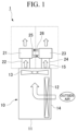
- FIG. 1 is a schematic view of a carbon dioxide recovery system 1 according to a first embodiment.
- the carbon dioxide recovery system 1 includes an outdoor unit 10, a recovery unit 21, and a separation unit 23.
- the outdoor unit 10 is a part of a first heat pump device and is used together with an indoor unit (not shown).
- the first heat pump device is an air conditioner having at least a function of cooling an indoor space.
- the outdoor unit 10 and the indoor unit are connected by a pipe (not shown) or the like for circulating a refrigerant.
- the outdoor unit 10 includes a housing 11, a heat exchanger 12, and a first blower 13.
- the outdoor unit 10 includes a compressor (not shown) and the like.
- a suction port 14 and a blowout port 15 are formed in the housing 11.
- the heat exchanger 12 and the first blower 13 are disposed inside the housing 11.
- the heat exchanger 12 causes heat exchange between the refrigerant and an outside air (air).
- the first blower 13 blows air from an inside of the outdoor unit 10 toward an outside.
- an upstream side in a flow direction of an airflow generated by the first blower 13 is simply referred to as an upstream side
- a downstream side in the flow direction of the airflow generated by the first blower 13 is simply referred to as a downstream side.
- the recovery unit 21 has a function of recovering carbon dioxide from the air.
- the recovery unit 21 is disposed downstream of the first blower 13.
- a first duct 22 that conveys the airflow from the first blower 13 to the recovery unit 21 is provided between the first blower 13 and the recovery unit 21.
- the recovery unit 21 has an adsorbent.
- the adsorbent includes a material capable of adsorbing carbon dioxide. Examples of the material capable of adsorbing carbon dioxide include amine, zeolite, silica gel, diatomaceous earth, alumina, and activated carbon. A plurality of materials may be selected from among the above, or materials other than the above may be selected.
- the adsorbent may be granular (for example, bead-shaped (spherical) or pellet-shaped (cylindrical)).
- a powdery adsorbent may be adopted. In this case, the powdery adsorbent may be carried on a surface of a base material.
- the base material may have, for example, a honeycomb shape.
- the powdered adsorbent may be carried on a honeycomb rotor.
- the adsorbent may be a liquid adsorbent.
- the recovery unit 21 is configured to hold the adsorbent at a position where the airflow generated by the first blower 13 is received.
- the recovery unit 21 may have a container that can accommodate the adsorbent and has air permeability.
- the container is disposed at the position where the airflow generated by the first blower 13 is received.
- the recovery unit 21 may have a support portion that supports the honeycomb rotor at the position where the airflow generated by the first blower 13 is received.
- the airflow blown out from the blowout port 15 by driving of the first blower 13 reaches the adsorbent held in the recovery unit 21. As a result, air enters the adsorbent or air inside the adsorbent is discharged.
- the recovery unit 21 brings the airflow generated by the first blower 13 into contact with the adsorbent so that carbon dioxide is adsorbed onto the adsorbent. That is, in the present embodiment, the recovery unit 21 uses blowing power of the first blower 13 to recover carbon dioxide.
- the separation unit 23 has a function of separating carbon dioxide from the adsorbent that has adsorbed carbon dioxide.
- the separation unit 23 is disposed downstream of the first blower 13.
- a second duct 24 that conveys an airflow from the first blower 13 to the separation unit 23 is provided between the first blower 13 and the separation unit 23.
- the separation unit 23 is configured to hold the adsorbent at a position where the airflow generated by the first blower 13 is received.
- the adsorbent that has adsorbed carbon dioxide in the recovery unit 21 is moved to the separation unit 23.
- the adsorbent from which the carbon dioxide has been separated in the separation unit 23 is moved to the recovery unit 21 again.
- the adsorbent may be transported (moved) from the recovery unit 21 to the separation unit 23 via a first pipe 25, and may be transported (moved) from the separation unit 23 to the recovery unit 21 via a second pipe 26.
- the honeycomb rotor is disposed across the recovery unit 21 and the separation unit 23, and the adsorbent may be moved between the recovery unit 21 and the separation unit 23 by rotation of the honeycomb rotor.
- the airflow blown out from the blowout port 15 by the driving of the first blower 13 reaches the adsorbent held in the separation unit 23.
- the air suctioned into the housing 11 from the suction port 14 is heated by the heat exchanger 12 to, for example, 45 °C to 70 °C.
- the first blower 13 sends out the airflow heated by the heat exchanger 12 toward the separation unit 23. Therefore, the airflow heated by the heat exchanger 12 reaches the adsorbent held in the separation unit 23.
- the separation unit 23 brings the heated airflow sent out from the first blower 13 into contact with the adsorbent to heat the adsorbent so that carbon dioxide is separated from the adsorbent.
- the separation unit 23 uses the blowing power of the first blower 13 to separate carbon dioxide.
- the carbon dioxide recovery system 1 includes the outdoor unit 10 of the first heat pump device, the outdoor unit 10 including the heat exchanger 12 and the first blower 13, the recovery unit 21 that has an adsorbent capable of adsorbing carbon dioxide and recovers the carbon dioxide from the air, and the separation unit 23 that separates the carbon dioxide from the adsorbent moved from the recovery unit 21.
- the first blower 13 sends out the airflow heated by the heat exchanger 12 toward the separation unit 23 in a case where the first heat pump device performs the cooling operation.
- the air heated by the heat exchanger 12 is supplied to the separation unit 23 using the blowing power of the first blower 13.
- the separation unit 23 uses heat of the air heated by the heat exchanger 12 as at least a portion of a heat source for the separation of carbon dioxide. Therefore, carbon dioxide can be separated with reduced energy consumption and cost, and an efficiency of carbon dioxide recovery is improved.
- the first blower 13 sends out the airflow that has passed through the heat exchanger 12 toward both the recovery unit 21 and the separation unit 23.
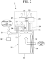
- FIG. 2 is a schematic view of the carbon dioxide recovery system 1 according to the second embodiment.
- the carbon dioxide recovery system 1 further includes a second blower 31, a control unit 32, and a junction portion 33.
- the second blower 31 supplies outside air or indoor air that has not passed through the heat exchanger 12 to the recovery unit 21 via the junction portion 33.
- a third duct 34 that conveys an airflow from the second blower 31 to the junction portion 33 is provided between the second blower 31 and the junction portion 33.
- the junction portion 33 is disposed between the first blower 13 and the recovery unit 21.
- the first duct 22 is provided between the first blower 13 and the junction portion 33, and conveys the airflow from the first blower 13 to the junction portion 33.
- the junction portion 33 mixes the air that has passed through the heat exchanger 12 from the first blower 13 with the outside air or indoor air that has not passed through the heat exchanger 12 from the second blower 31, and supplies the mixed air to the recovery unit 21.
- the airflow by the first blower 13 is mixed with the outside air or indoor air sent out by the second blower 31 to be decreased in temperature, and then is supplied to the recovery unit 21.
- a temperature sensor (not shown) that measures the temperature of the mixed air is provided in the junction portion 33.
- the airflow of the mixed air which is a mixture of the air from the first blower 13 and the outside air or indoor air from the second blower 31, reaches the adsorbent held in the recovery unit 21.
- the airflow of the mixed air and the adsorbent are brought into contact with each other so that carbon dioxide is adsorbed onto the adsorbent. That is, in the present embodiment, the recovery unit 21 uses the blowing power of the first blower 13 and the second blower 31 to recover carbon dioxide.
- the control unit 32 controls each component of the carbon dioxide recovery system 1.
- the control unit 32 controls a flow rate of the air supplied from the second blower 31 to the junction portion 33 based on measurement results of the temperature sensor provided in the junction portion 33.
- the control unit 32 may control the flow rate of the air from the second blower 31 by controlling an opening degree of a flow control valve provided in the third duct 34.
- the control unit 32 may control the flow rate of the air from the second blower 31 by controlling a rotation speed of the second blower 31.
- the carbon dioxide recovery system 1 further includes the second blower 31 that supplies the outside air or indoor air that has not passed through the heat exchanger 12 to the recovery unit 21.
- the outside air or indoor air from the second blower 31 can be used for the recovery of carbon dioxide in the recovery unit 21.
- a temperature of the air in contact with the adsorbent is high, there are cases where an efficiency of carbon dioxide adsorption by the adsorbent is reduced.
- a carbon dioxide concentration in the indoor air often increases due to human respiration.
- the indoor air is supplied to the recovery unit 21 by the second blower 31, carbon dioxide can be recovered from the air having a high carbon dioxide concentration, so that the efficiency of carbon dioxide recovery is further improved.
- the temperature of the air supplied to the recovery unit 21 can be decreased compared to a case where only the air from the first blower 13 is supplied to the recovery unit 21.
- the control unit 32 controls the flow rate of the air supplied from the second blower 31 to the junction portion 33 based on the measurement results of the temperature sensor that measures the temperature of the mixed air, whereby the temperature of the air in contact with the adsorbent can be more reliably adjusted to a temperature suitable for the adsorption of carbon dioxide.
- FIG. 3 is a schematic view of the carbon dioxide recovery system 1 according to the third embodiment.
- the carbon dioxide recovery system 1 further includes a restricting unit 35.
- the restricting unit 35 is provided between the first blower 13 and the recovery unit 21.
- the restricting unit 35 restricts the airflow generated by the first blower 13 from reaching the recovery unit 21.
- the restricting unit 35 is, for example, a plate-shaped member that blocks the airflow from the first blower 13 toward the recovery unit 21.
- the recovery unit 21 uses the blowing power of the second blower 31 to recover carbon dioxide.
- the carbon dioxide recovery system 1 further includes the restricting unit 35 that is provided between the first blower 13 and the recovery unit 21, and that restricts the airflow heated by the heat exchanger 12 from reaching the recovery unit 21.
- the recovery unit 21 is not supplied with the air heated by the heat exchanger 12, and is supplied with only the outside air or indoor air that has not passed through the heat exchanger 12 from the second blower 31. Therefore, it is possible to prevent a decrease in the efficiency of carbon dioxide adsorption by the adsorbent due to an increase in the temperature of the air supplied to the recovery unit 21.
- the air heated by the heat exchanger 12 is supplied only to the separation unit 23, an amount of the air supplied to the separation unit 23 can be increased. Therefore, the efficiency of carbon dioxide recovery is improved.
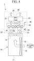
- FIG. 4 is a schematic view of the carbon dioxide recovery system 1 according to the fourth embodiment.
- the carbon dioxide recovery system 1 further includes a second heat pump device 40.
- the second heat pump device 40 is provided between the first blower 13, and the recovery unit 21 and the separation unit 23.
- the second heat pump device 40 includes an evaporator 41, a condenser 42, a compressor 43, and an expansion valve 44.
- a refrigerant circulates between the evaporator 41 and the condenser 42. Specifically, the refrigerant in a gaseous state compressed by the compressor 43 flows into the condenser 42. The refrigerant in the condenser 42 exchanges heat with a surrounding air, thereby heating the surrounding air. The refrigerant that has entered a liquid state due to the heat exchange is expanded by the expansion valve 44 and flows into the evaporator 41. The refrigerant in the evaporator 41 exchanges heat with the surrounding air, thereby cooling the surrounding air. The refrigerant that has entered the gaseous state due to the heat exchange is returned to the compressor 43.
- the condenser 42 is located between the first blower 13 and the separation unit 23.
- the second duct 24 is provided between the first blower 13 and the condenser 42, and conveys the airflow from the first blower 13 to the condenser 42.
- the air from the first blower 13 is heated by passing through the condenser 42 and is supplied to the separation unit 23.
- the carbon dioxide recovery system 1 further includes the second heat pump device 40 including the evaporator 41 and the condenser 42.
- the evaporator 41 is located between the first blower 13 and the recovery unit 21, and the condenser 42 is located between the first blower 13 and the separation unit 23.
- the temperature of the air supplied to the recovery unit 21 can be adjusted to a temperature suitable for the adsorption of carbon dioxide by the adsorbent.
- the temperature of the air supplied to the separation unit 23 can be adjusted to a temperature suitable for the separation of carbon dioxide from the adsorbent. Therefore, the efficiency of carbon dioxide recovery can be improved.
- a humidity of the air in contact with the adsorbent is high, there is a probability that the efficiency of carbon dioxide adsorption by the adsorbent is reduced.
- the evaporator 41 dehumidifies the air supplied to the recovery unit 21, thereby preventing a decrease in the adsorption efficiency.
- the temperature suitable for the adsorption of carbon dioxide by the adsorbent is, for example, 5 °C to 30 °C, and the temperature suitable for the separation of carbon dioxide from the adsorbent is, for example, 60 °C to 120 °C.
- the present invention is not limited thereto, and the suitable temperature varies depending on a specific material of the adsorbent.
- the first heat pump device is an air conditioner having a function of cooling and heating an indoor space
- the first heat pump device performs the cooling operation and the heating operation according to the season, temperature, and the like.
- the first blower 13 supplies the airflow cooled by the heat exchanger 12 to the recovery unit 21 by passing the airflow through the evaporator 41 and supplies the airflow to the separation unit 23 by passing the airflow through the condenser 42.
- the airflow cooled by the heat exchanger 12 can be heated by the condenser 42 and supplied to the separation unit 23. Therefore, the carbon dioxide can be recovered and separated even in a case where the first heat pump device performs the heating operation.
- the second heat pump device 40 may operate in a transcritical heat pump cycle in which the refrigerant operates at a pressure higher than a critical pressure.
- a working fluid used in the transcritical heat pump cycle is a refrigerant primarily containing a carbon dioxide refrigerant. Examples of the working fluid used in the transcritical heat pump cycle include the carbon dioxide refrigerant and a mixed refrigerant using the carbon dioxide refrigerant.
- FIG. 12A is an example of a T-s diagram of the general vapor compression type heat pump cycle.
- FIG. 12B is a schematic view of a heat pump cycle.
- a vertical axis represents a temperature
- a horizontal axis represents an entropy.
- the refrigerant flowing through an inside of the condenser 42 has a gas single-phase region (region from state 1 to state 1a), a gas-liquid two-phase region (region from state 1a to state 1b), and a liquid single-phase region (region from state 1b to state 2).
- the gas-liquid two-phase region (the region from state 1a to state 1b) is a latent heat region, and in this region, a gas refrigerant liquefies without a temperature change.
- a difference in temperature between the refrigerant and the air is large during a process from state 1 to state 2.
- FIG. 13 is an example of a T-s diagram of the transcritical heat pump cycle.
- a vertical axis represents a temperature
- a horizontal axis represents an entropy.
- the refrigerant flowing through the inside of the condenser 42 becomes a refrigerant in a supercritical state. Since a specific heat of the refrigerant in the supercritical state changes, the refrigerant does not have a latent heat region, and the temperature of the refrigerant changes throughout the entire process from state 1 to state 2. Therefore, it is easy to create a difference in temperature between the refrigerant and the air, and it is possible to reduce energy loss. In addition, since the temperature of the refrigerant is likely to change, the temperature of the refrigerant can be easily increased.
- the air from the first blower 13 can be efficiently heated by the condenser 42. Therefore, the temperature of the air supplied to the separation unit 23 can be increased, and the efficiency of carbon dioxide recovery can be improved.
- the second heat pump device 40 may use a non-azeotropic mixed refrigerant having different boiling points as the working fluid.
- a non-azeotropic mixed refrigerant having different boiling points as the working fluid.
- the mixed refrigerant a mixture of carbon dioxide as a primary component and other refrigerant (propane, chlorofluorocarbon, or the like) having a different boiling point from that of the carbon dioxide may be used.
- FIG. 14 is an example of a T-s diagram of a heat pump cycle using the non-azeotropic mixed refrigerant.
- a vertical axis represents a temperature
- a horizontal axis represents an entropy.
- the refrigerant flowing through the inside of the condenser 42 has a latent heat region (region from state 1a to state 1b) with a temperature change. Since the temperature of the refrigerant also changes in the latent heat region, it is easy to create a difference in temperature between the refrigerant and the air, and it is easy to increase the temperature of the refrigerant.
- the second heat pump device 40 uses the non-azeotropic mixed refrigerant with different boiling points as the working fluid, the air from the first blower 13 can be efficiently heated by the condenser 42. Therefore, the temperature of the air supplied to the separation unit 23 can be increased, and the efficiency of carbon dioxide recovery can be improved. In addition, since an internal pressure of the second heat pump device 40 can be lowered compared to a case where a single refrigerant is used as the working fluid, a pressure-resistant strength design of the device can be relaxed.
- FIG. 5 is a schematic view of the carbon dioxide recovery system 1 according to the fifth embodiment.
- the present embodiment is a combination of the second embodiment and the fourth embodiment. That is, the carbon dioxide recovery system 1 according to the embodiment includes the outdoor unit 10, the recovery unit 21, the separation unit 23, the second blower 31, the control unit 32, the junction portion 33, and the second heat pump device 40.
- the junction portion 33 is disposed between the first blower 13 and the evaporator 41.
- the first duct 22 is provided between the first blower 13 and the junction portion 33, and conveys the airflow from the first blower 13 toward the evaporator 41.
- the junction portion 33 mixes the air that has passed through the heat exchanger 12 from the first blower 13 with the outside air or indoor air that has not passed through the heat exchanger 12 from the second blower 31, and sends out the mixed air toward the evaporator 41.
- the mixed air is cooled by passing through the evaporator 41 and is supplied to the recovery unit 21.
- a temperature sensor is provided immediately before the recovery unit 21 and measures the temperature of the air immediately before being supplied to the recovery unit 21 (that is, the air after passing through the evaporator 41).
- the control unit 32 controls the flow rate of the air supplied from the second blower 31 to the junction portion 33 based on the measurement results of the temperature sensor.
- the second blower 31 supplies the outside air or indoor air that has not passed through the heat exchanger 12 to the recovery unit 21 by passing the outside air or indoor air through the evaporator 41.
- the outside air or indoor air from the second blower 31 can be used for the recovery of carbon dioxide in the recovery unit 21.
- the outside air or indoor air from the second blower 31 can be cooled and dehumidified by the evaporator 41 and be supplied to the recovery unit 21. Therefore, the efficiency of carbon dioxide recovery is improved.
- the airflow by the first blower 13 is mixed with the outside air or indoor air sent out by the second blower 31 to be increased in temperature, and is supplied to the recovery unit 21.
- the airflow by the first blower 13 is cooled by the heat exchanger 12.
- the temperature of the air supplied to the recovery unit 21 is too low, there are cases where the efficiency of carbon dioxide adsorption is reduced.
- the airflow by the first blower 13 is mixed with the outside air or indoor air sent out by the second blower 31 to be increased in temperature, and is supplied to the recovery unit 21. As a result, it is possible to prevent a decrease in the efficiency of carbon dioxide adsorption.
- a temperature of the indoor air is higher than a temperature of the outside air.
- the temperature of the airflow by the first blower 13 can be more effectively increased.
- FIG. 6 is a schematic view of the carbon dioxide recovery system 1 according to the sixth embodiment.
- the carbon dioxide recovery system 1 further includes the restricting unit 35.
- the restricting unit 35 is provided in the first duct 22 or the second duct 24.
- the restricting unit 35 restricts at least a portion of the airflow generated by the first blower 13 from reaching the evaporator 41 or the condenser 42.
- the restricting unit 35 may be a plate-shaped member that is provided in the first duct 22 or the second duct 24 and blocks the airflow from the first blower 13 toward the evaporator 41 or the condenser 42.
- the restricting unit 35 may be movable between the first duct 22 and the second duct 24. In this case, a flow passage opening rate of the first duct 22 or the second duct 24 by the restricting unit 35 is changed by changing a position of the restricting unit 35 with respect to the first duct 22 or the second duct 24.
- the restricting unit 35 may be a flow control valve provided in each of the first duct 22 and the second duct 24.
- the flow passage opening rate of the first duct 22 by the restricting unit 35 is changed by changing an opening degree of the flow control valve provided in the first duct 22, and the flow passage opening rate of the second duct 24 by the restricting unit 35 is changed by changing an opening degree of the flow control valve provided in the second duct 24.
- the control unit 32 controls the flow passage opening rates of the first duct 22 and the second duct 24 by the restricting unit 35 according to an operation mode of the first heat pump device and the like.
- the control unit 32 controls the restricting unit 35 such that the flow passage opening rate of the first duct 22 is 0 % and the flow passage opening rate of the second duct 24 is 100 %.
- the control unit 32 moves the restricting unit 35 to the first duct 22.
- the control unit 32 sets the opening degree of the flow control valve provided in the first duct 22 to 0 % and sets the opening degree of the flow control valve provided in the second duct 24 to 100 %.
- the airflow heated by the heat exchanger 12 is restricted from reaching the evaporator 41 (that is, from being supplied to the recovery unit 21). Therefore, it is possible to prevent a decrease in the efficiency of carbon dioxide adsorption by the adsorbent due to an increase in the temperature of the air supplied to the recovery unit 21.
- the control unit 32 controls the restricting unit 35 such that the flow passage opening rate of the first duct 22 is 100 % and the flow passage opening rate of the second duct 24 is 0 %.
- the control unit 32 moves the restricting unit 35 to the second duct 24.
- the control unit 32 sets the opening degree of the flow control valve provided in the first duct 22 to 100 % and sets the opening degree of the flow control valve provided in the second duct 24 to 0 %.
- the airflow cooled by the heat exchanger 12 is restricted from reaching the condenser 42 (that is, from being supplied to the separation unit 23). Therefore, it is possible to prevent a decrease in the efficiency of carbon dioxide recovery due to a decrease in the temperature of the air supplied to the separation unit 23.
- the second blower 31 may blow air toward the condenser 42 (that is, the separation unit 23).
- control of the flow passage opening rate by the control unit 32 is not limited thereto, and the flow passage opening rate may be optionally changed according to seasonal conditions.
- control unit 32 may control the restricting unit 35 such that the flow passage opening rate of the first duct 22 is 0 % and the flow passage opening rate of the second duct 24 is 100 % even in a case where the first heat pump device performs the heating operation.
- the airflow cooled by the heat exchanger 12 can be heated by the condenser 42 and supplied to the separation unit 23, so that the separation of carbon dioxide can be performed.
- the air from the first blower 13 is dehumidified by passing through the heat exchanger 12, the temperature is easily increased by the condenser 42.
- control unit 32 can set the flow passage opening rates of the first duct 22 and the second duct 24 to any value between 0 % and 100 %.
- the carbon dioxide recovery system 1 includes the second heat pump device 40 including the evaporator 41 and the condenser 42, the restricting unit 35 that is provided in the first duct 22 that conveys the airflow from the first blower 13 toward the evaporator 41 or in the second duct 24 that conveys the airflow from the first blower 13 toward the condenser 42 and that restricts at least a portion of the airflow generated by the first blower 13 from reaching the evaporator 41 or the condenser 42, and the control unit 32 that controls the flow passage opening rates of the first duct 22 and the second duct 24 by the restricting unit 35.
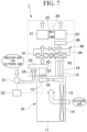
- FIG. 7 is a schematic view of the carbon dioxide recovery system 1 according to the seventh embodiment.
- the carbon dioxide recovery system 1 further includes a heater 46.
- the heater 46 is disposed between the condenser 42 and the separation unit 23.
- the heater 46 further heats the air that has been heated by passing through the condenser 42 and supplies the heated air to the separation unit 23. As a result, the efficiency of carbon dioxide recovery can be further improved.
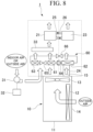
- FIG. 8 is a schematic view of the carbon dioxide recovery system 1 according to the eighth embodiment.
- the carbon dioxide recovery system 1 includes a second heat pump device 60 instead of the second heat pump device 40.
- the second heat pump device 60 is provided between the first blower 13, and the recovery unit 21 and the separation unit 23.
- the second heat pump device 60 includes an evaporator 61, a first condenser 62, a second condenser 63, a compressor 64, a first regulating valve 65, and a second regulating valve 66.
- the evaporator 61 is located between the first blower 13 and the junction portion 33.
- the air from the first blower 13 and a portion of the air from the second blower 31 are cooled by passing through the evaporator 61 and are supplied to the junction portion 33.
- the second condenser 63 is located between the first blower 13 and the junction portion 33.
- the air from the first blower 13 and another portion of the air from the second blower 31 are heated by passing through the second condenser 63 and are supplied to the junction portion 33.
- the junction portion 33 is disposed between the second heat pump device 60 and the recovery unit 21.
- the junction portion 33 mixes the air cooled by the evaporator 61 with the air heated by the second condenser 63, and supplies the mixed air to the recovery unit 21.
- the first condenser 62 is located between the first blower 13 and the separation unit 23.
- the air from the first blower 13 is heated by passing through the first condenser 62 and is supplied to the separation unit 23.
- the first regulating valve 65 is located between the evaporator 61 and the second condenser 63.
- the first regulating valve 65 is an expansion valve that expands the refrigerant.
- the second regulating valve 66 is located between the first condenser 62 and the second condenser 63.
- the second regulating valve 66 adjusts an amount of the refrigerant flowing through the first condenser 62 and the second condenser 63.
- the control unit 32 may control the second regulating valve 66 based on the measurement results of the temperature sensor provided in the junction portion 33.
- the carbon dioxide recovery system 1 includes the second heat pump device 60 including the evaporator 61, the first condenser 62, the second condenser 63, the first regulating valve 65 located between the evaporator 61 and the second condenser 63, and the second regulating valve 66 located between the first condenser 62 and the second condenser 63.
- the evaporator 61 and the second condenser 63 are located between the first blower 13 and the recovery unit 21, and the first condenser 62 is located between the first blower 13 and the separation unit 23.
- the temperature of the air supplied to the recovery unit 21 can be more accurately adjusted. Therefore, the efficiency of carbon dioxide recovery is further improved.
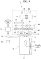
- FIG. 9 is a schematic view of the carbon dioxide recovery system 1 according to the ninth embodiment.
- the carbon dioxide recovery system 1 further includes a total heat exchanger 71.
- the total heat exchanger 71 is disposed upstream of the second blower 31.
- the second blower 31 supplies the indoor air that has passed through the total heat exchanger 71 to the recovery unit 21.
- exhaust heat of the indoor air is recovered by the total heat exchanger 71 and then supplied to the recovery unit 21. Therefore, it is possible to improve an energy efficiency of the entire system.
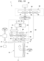
- FIG. 10 is a schematic view of the carbon dioxide recovery system 1 according to the tenth embodiment.
- the carbon dioxide recovery system 1 further includes a third heat pump device 80, a carbon dioxide tank 85, and a first supply path 86.
- the third heat pump device 80 is located downstream of the separation unit 23.
- the third heat pump device 80 includes an evaporator 81, a condenser (third condenser) 82, a compressor 83, and an expansion valve 84.
- Gas discharged from the separation unit 23, containing a high concentration of carbon dioxide, is cooled by passing through the evaporator 81. As a result, the carbon dioxide is liquefied. The liquefied carbon dioxide is stored in the carbon dioxide tank 85.
- the condenser 82 heats a surrounding fluid (for example, air or water).
- the first supply path 86 connects the condenser 82 to the second duct 24.
- the fluid heated in the condenser 82 is supplied to the separation unit 23 via the first supply path 86 and the second duct 24.
- the fluid heated in the condenser 82 may be directly supplied to the separation unit 23 via the first supply path 86.
- the carbon dioxide recovery system 1 further includes the third heat pump device 80 that liquefies the carbon dioxide separated from the adsorbent in the separation unit 23.
- the carbon dioxide separated in the separation unit 23 can be liquefied and stored in a low volume.
- the carbon dioxide recovery system 1 further includes the first supply path 86 that supplies the fluid heated in the condenser 82 of the third heat pump device 80 to the separation unit 23.
- heat of the fluid heated in the condenser 82 can be used as a portion of the heat source for the separation of carbon dioxide. Therefore, the efficiency of carbon dioxide recovery can be further improved.
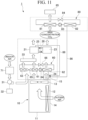
- FIG. 11 is a schematic view of the carbon dioxide recovery system 1 according to the eleventh embodiment.
- the carbon dioxide recovery system 1 further includes a second supply path 88.
- Gas after the carbon dioxide is recovered is discharged from the recovery unit 21.
- the second supply path 88 connects the recovery unit 21 to the second duct 24.
- the gas discharged from the recovery unit 21 is supplied to the separation unit 23 via the second supply path 88 and the second duct 24.
- the gas discharged from the recovery unit 21 may be directly supplied to the separation unit 23 via the second supply path 88.
- the carbon dioxide recovery system 1 further includes the second supply path 88 that supplies the gas discharged from the recovery unit 21 to the separation unit 23.
- the adsorbent adsorbs carbon dioxide
- adsorption heat is generated.
- the adsorption heat can be used as a portion of the heat source for the separation of carbon dioxide. Therefore, the efficiency of carbon dioxide recovery can be further improved.
- FIG. 15 is a schematic view of the carbon dioxide recovery system 1 according to the twelfth embodiment.
- the carbon dioxide recovery system 1 includes a liquefaction system 100 instead of the third heat pump device 80.
- the liquefaction system 100 includes a liquefaction heat exchanger 101, a compressor 103, and a vortex tube 104.
- the liquefaction system 100 uses cold energy generated by the vortex tube 104 to liquefy the carbon dioxide separated from the adsorbent in the separation unit 23.
- the liquefaction system 100 need only include at least one liquefaction heat exchanger 101, and may include a plurality of the liquefaction heat exchangers 101.
- the compressor 103 supplies compressed gas obtained by compressing air, dry air, or the like to the vortex tube 104.
- FIG. 16 is a schematic view of the vortex tube 104.
- the vortex tube 104 includes a main body portion 104a, a cold air outlet 104b, a warm air outlet 104c, a compressed gas supply port 104d, and a valve 104e.
- the main body portion 104a has a cylindrical shape extending in a longitudinal direction.
- the cold air outlet 104b is provided at one end of the main body portion 104a in the longitudinal direction.
- the warm air outlet 104c is provided at the other end of the main body portion 104a in the longitudinal direction.
- the compressed gas supply port 104d is provided at a side surface of the main body portion 104a.
- the compressed gas supply port 104d is provided close to the cold air outlet 104b.
- the compressed gas is supplied to the compressed gas supply port 104d from the compressor 103.
- the compressed gas is introduced into an inside of the main body portion 104a from the compressed gas supply port 104d.
- the compressed gas supply port 104d is configured such that the compressed gas introduced from the compressed gas supply port 104d to the inside of the main body portion 104a forms a swirling flow along an inner peripheral surface of the main body portion 104a.
- the valve 104e is provided inside the main body portion 104a.
- the valve 104e is provided close to the warm air outlet 104c.
- the valve 104e narrows a flow passage area of the swirling flow compared to a cross sectional area of the main body portion 104a.
- the valve 104e allows a portion of the gas forming the swirling flow to be discharged from the warm air outlet 104c and prevents the discharge of the remaining gas.
- the compressed gas is introduced from the compressor 103 into the compressed gas supply port 104d.
- the compressed gas forms an outer swirling flow Q along the inner peripheral surface of the main body portion 104a.
- This gas flows toward the warm air outlet 104c (valve 104e) while being pressed against the inner peripheral surface of the main body portion 104a.
- a temperature of the gas increases as the gas flows toward the warm air outlet 104c.
- a pressure near the inner peripheral surface of the main body portion 104a is higher than a pressure at a center portion of the main body portion 104a. Due to this pressure difference, the temperature of the gas flowing near the inner peripheral surface of the main body portion 104a is higher than a temperature of the gas flowing through the center portion of the main body portion 104a.
- T1 a temperature of the compressed gas supplied from the compressed gas supply port 104d
- T2 a temperature of the first fluid F1 discharged from the warm air outlet 104c
- T3 a temperature of the second fluid F2 discharged from the cold air outlet 104b
- the vortex tube 104 rotates the compressed gas introduced from the compressor 103 inside the main body portion 104a at a high speed, and uses the swirling flows generated by the high-speed rotation and a pressure difference due to compression and expansion of the gas to separate the compressed gas into the high-temperature first fluid F1 (warm air) and the low-temperature second fluid F2 (cold air).
- cold energy can be generated with a simple configuration.
- the temperature, the heat value, and the like of the cold energy can be adjusted, for example, by the pressure, the temperature, and the flow rate of the compressed gas supplied to the vortex tube 104, the flow rates of the first fluid F1 and the second fluid F2, and the like.
- the flow rates of the first fluid F1 and the second fluid F2 can be adjusted by the valve 104e.
- the second fluid F2 discharged from the cold air outlet 104b is supplied to the liquefaction heat exchanger 101.
- the liquefaction heat exchanger 101 causes heat exchange between the second fluid F2 and the carbon dioxide separated from the adsorbent in the separation unit 23, thereby cooling and liquefying carbon dioxide.
- the liquefied carbon dioxide is stored in the carbon dioxide tank 85.
- the first fluid F1 discharged from the warm air outlet 104c may be supplied to the separation unit 23 via a third supply path 105.
- heat of the high-temperature first fluid F1 can be used as a portion of the heat source for the separation of carbon dioxide.
- the second fluid F2 after the heat exchange in the liquefaction heat exchanger 101 may be supplied to the recovery unit 21 via a fourth supply path 106.
- energy of the compressed gas introduced into the vortex tube 104 can be reused as power for supplying air to the recovery unit 21.
- the first fluid F1 may not be supplied to the separation unit 23.
- the second fluid F2 may not be supplied to the recovery unit 21.
- the carbon dioxide recovery system 1 further includes the vortex tube 104 that separates the compressed air into the first fluid F1 and the second fluid F2 having a lower temperature than the first fluid F1, and discharges the first fluid F1 and the second fluid F2 separately, and the liquefaction heat exchanger 101 that causes the heat exchange between the second fluid F2 and the carbon dioxide separated from the adsorbent in the separation unit 23, thereby liquefying the carbon dioxide.
- the carbon dioxide separated in the separation unit 23 can be liquefied and stored in a low volume.
- carbon dioxide can be liquefied with a simple configuration.
- the carbon dioxide recovery system 1 further includes the third supply path 105 that supplies the first fluid F1 discharged from the vortex tube 104 to the separation unit 23.
- the heat of the high-temperature first fluid F1 can be used as a portion of the heat source for the separation of carbon dioxide. Therefore, the efficiency of carbon dioxide recovery can be further improved.
- the junction portion 33 is disposed upstream of the evaporator 41, but the present invention is not limited thereto.
- the junction portion 33 may be disposed downstream of the evaporator 41.
- one evaporator 61 and one second condenser 63 are provided between the first blower 13 and the recovery unit 21, but the present invention is not limited thereto. Two or more evaporators may be provided between the first blower 13 and the recovery unit 21, and two or more condensers may be provided between the first blower 13 and the recovery unit 21.
- the second condenser 63 may be located between the evaporator 61 and the recovery unit 21. In this case, the air dehumidified by the evaporator 61 is heated by the second condenser 63 and supplied to the recovery unit 21.
- the total heat exchanger 71 of the ninth embodiment may be provided in the carbon dioxide recovery system 1 of the first to eighth embodiments.
- the third heat pump device 80 and the first supply path 86 of the tenth embodiment may be provided in the carbon dioxide recovery system 1 of the first to eighth embodiments.
- the second supply path 88 of the eleventh embodiment may be provided in the carbon dioxide recovery system 1 of the first to ninth embodiments.
- the liquefaction system 100 according to the twelfth embodiment may be provided in the carbon dioxide recovery system 1 according to the first to ninth embodiments.
- control unit 32 includes a computer system therein.
- a program for implementing functions of each configuration provided by the carbon dioxide recovery system 1 described above may be recorded on a computer-readable recording medium, and by having the computer system read and execute the program recorded on this recording medium, processing in the control unit 32 described above may be performed.
- hardware other than the control unit 32 may perform the above-described processing.
- “having the computer system read and execute the program recorded on the recording medium” includes installing the program on the computer system.
- the "computer system” mentioned here includes an operating system (OS) and hardware such as a peripheral device.
- the "computer system” may include a plurality of computer devices connected via a network including a communication line such as the Internet, a WAN, a LAN, and a dedicated line.
- the "computer-readable recording medium” refers to a portable medium such as a flexible disk, a magneto-optical disk, a ROM, or a CD-ROM, and a storage device such as a hard disk built in a computer system.
- the recording medium on which the program is stored may be a non-transitory recording medium such as a CD-ROM.
- the recording medium also includes an internal or external recording medium that is accessible by a distribution server to distribute the program.
- a configuration may be adopted in which the program is divided into a plurality of programs and the plurality of programs are downloaded at different times and then combined in each configuration provided by the carbon dioxide recovery system 1, or the distribution server that distributes each of the divided programs may be different.
- the "computer-readable recording medium” also includes a medium that holds the program for a certain period of time, such as a volatile memory (RAM) inside the computer system that serves as a server or a client in a case where the program is transmitted via a network.
- the program may be a program for implementing some of the functions described above.
- the program may be a so-called difference file (difference program) capable of implementing the functions described above in combination with a program that has already been recorded on the computer system.
Landscapes
- Engineering & Computer Science (AREA)
- Chemical & Material Sciences (AREA)
- Mechanical Engineering (AREA)
- General Engineering & Computer Science (AREA)
- Chemical Kinetics & Catalysis (AREA)
- General Chemical & Material Sciences (AREA)
- Combustion & Propulsion (AREA)
- Analytical Chemistry (AREA)
- Oil, Petroleum & Natural Gas (AREA)
- Thermal Sciences (AREA)
- Physics & Mathematics (AREA)
- Carbon And Carbon Compounds (AREA)
- Other Air-Conditioning Systems (AREA)
- Separation Of Gases By Adsorption (AREA)
- Solid-Sorbent Or Filter-Aiding Compositions (AREA)
Abstract
Description
- The present invention relates to a carbon dioxide recovery system.
-
Patent Document 1 discloses a device that removes carbon dioxide from the air using an adsorbent capable of adsorbing carbon dioxide. - Patent Document 1: Japanese Unexamined Patent Application, First Publication
JP 2020- 131 166 A - There is a demand for improving an efficiency of carbon dioxide recovery using an adsorbent. In a configuration of
Patent Document 1, a decompression pump is used to separate carbon dioxide from the adsorbent, which results in an increase in energy required for the separation. - In view of the above circumstances, an object of the present disclosure is to provide a carbon dioxide recovery system capable of improving an efficiency of carbon dioxide recovery.
- An aspect of a carbon dioxide recovery system according to the present invention includes an outdoor unit of a first heat pump device, the outdoor unit including a heat exchanger and a first blower, a recovery unit that has an adsorbent onto which carbon dioxide is adsorbable and is configured to recover carbon dioxide from air, and a separation unit configured to separate the carbon dioxide from the adsorbent moved from the recovery unit, in which the first blower sends out an airflow heated by the heat exchanger toward the separation unit in a case where the first heat pump device performs a cooling operation.
- According to the present invention, it is possible to provide a carbon dioxide recovery system capable of improving an efficiency of carbon dioxide recovery.
-
-
FIG. 1 A schematic view of a carbon dioxide recovery system according to a first embodiment. -
FIG. 2 A schematic view of a carbon dioxide recovery system according to a second embodiment. -
FIG. 3 A schematic view of a carbon dioxide recovery system according to a third embodiment. -
FIG. 4 A schematic view of a carbon dioxide recovery system according to a fourth embodiment. -
FIG. 5 A schematic view of a carbon dioxide recovery system according to a fifth embodiment. -
FIG. 6 A schematic view of a carbon dioxide recovery system according to a sixth embodiment. -
FIG. 7 A schematic view of a carbon dioxide recovery system according to a seventh embodiment. -
FIG. 8 A schematic view of a carbon dioxide recovery system according to an eighth embodiment. -
FIG. 9 A schematic view of a carbon dioxide recovery system according to a ninth embodiment. -
FIG. 10 A schematic view of a carbon dioxide recovery system according to a tenth embodiment. -
FIG. 11 A schematic view of a carbon dioxide recovery system according to an eleventh embodiment. -
FIG. 12A An example of a T-s diagram of a general vapor compression type heat pump cycle. -
FIG. 12B A schematic view of a heat pump cycle. -
FIG. 13 An example of a T-s diagram of a transcritical heat pump cycle. -
FIG. 14 An example of a T-s diagram of a heat pump cycle using a non-azeotropic mixed refrigerant. -
FIG. 15 A schematic view of a carbon dioxide recovery system according to a twelfth embodiment. -
FIG. 16 A schematic view of a vortex tube according to the twelfth embodiment. - Hereinafter, an embodiment of the present invention will be described with reference to the drawings. The scope of the present invention is not limited to the following embodiment, and can be changed in any way within the scope of technical ideas of the present invention.
-
FIG. 1 is a schematic view of a carbondioxide recovery system 1 according to a first embodiment. - As shown in
FIG. 1 , the carbondioxide recovery system 1 includes anoutdoor unit 10, arecovery unit 21, and aseparation unit 23. - The
outdoor unit 10 is a part of a first heat pump device and is used together with an indoor unit (not shown). In the present embodiment, the first heat pump device is an air conditioner having at least a function of cooling an indoor space. Theoutdoor unit 10 and the indoor unit are connected by a pipe (not shown) or the like for circulating a refrigerant. - The
outdoor unit 10 includes ahousing 11, aheat exchanger 12, and afirst blower 13. In addition, theoutdoor unit 10 includes a compressor (not shown) and the like. - A
suction port 14 and ablowout port 15 are formed in thehousing 11. Theheat exchanger 12 and thefirst blower 13 are disposed inside thehousing 11. Theheat exchanger 12 causes heat exchange between the refrigerant and an outside air (air). Thefirst blower 13 blows air from an inside of theoutdoor unit 10 toward an outside. - When the
first blower 13 is driven, air is suctioned into thehousing 11 from thesuction port 14. The air suctioned into thehousing 11 passes through theheat exchanger 12 and is blown out from theblowout port 15 to the outside of thehousing 11. - Hereinafter, an upstream side in a flow direction of an airflow generated by the
first blower 13 is simply referred to as an upstream side, and a downstream side in the flow direction of the airflow generated by thefirst blower 13 is simply referred to as a downstream side. - The
recovery unit 21 has a function of recovering carbon dioxide from the air. Therecovery unit 21 is disposed downstream of thefirst blower 13. Afirst duct 22 that conveys the airflow from thefirst blower 13 to therecovery unit 21 is provided between thefirst blower 13 and therecovery unit 21. - The
recovery unit 21 has an adsorbent. The adsorbent includes a material capable of adsorbing carbon dioxide. Examples of the material capable of adsorbing carbon dioxide include amine, zeolite, silica gel, diatomaceous earth, alumina, and activated carbon. A plurality of materials may be selected from among the above, or materials other than the above may be selected. The adsorbent may be granular (for example, bead-shaped (spherical) or pellet-shaped (cylindrical)). Alternatively, a powdery adsorbent may be adopted. In this case, the powdery adsorbent may be carried on a surface of a base material. The base material may have, for example, a honeycomb shape. For example, the powdered adsorbent may be carried on a honeycomb rotor. The adsorbent may be a liquid adsorbent. - The
recovery unit 21 is configured to hold the adsorbent at a position where the airflow generated by thefirst blower 13 is received. - For example, the
recovery unit 21 may have a container that can accommodate the adsorbent and has air permeability. In this case, the container is disposed at the position where the airflow generated by thefirst blower 13 is received. - Alternatively, for example, in a case where the adsorbent is carried on the honeycomb rotor, the
recovery unit 21 may have a support portion that supports the honeycomb rotor at the position where the airflow generated by thefirst blower 13 is received. - The airflow blown out from the
blowout port 15 by driving of thefirst blower 13 reaches the adsorbent held in therecovery unit 21. As a result, air enters the adsorbent or air inside the adsorbent is discharged. Therecovery unit 21 brings the airflow generated by thefirst blower 13 into contact with the adsorbent so that carbon dioxide is adsorbed onto the adsorbent. That is, in the present embodiment, therecovery unit 21 uses blowing power of thefirst blower 13 to recover carbon dioxide. - The
separation unit 23 has a function of separating carbon dioxide from the adsorbent that has adsorbed carbon dioxide. Theseparation unit 23 is disposed downstream of thefirst blower 13. Asecond duct 24 that conveys an airflow from thefirst blower 13 to theseparation unit 23 is provided between thefirst blower 13 and theseparation unit 23. Theseparation unit 23 is configured to hold the adsorbent at a position where the airflow generated by thefirst blower 13 is received. - The adsorbent that has adsorbed carbon dioxide in the
recovery unit 21 is moved to theseparation unit 23. In addition, the adsorbent from which the carbon dioxide has been separated in theseparation unit 23 is moved to therecovery unit 21 again. - As shown in
FIG. 1 , the adsorbent may be transported (moved) from therecovery unit 21 to theseparation unit 23 via afirst pipe 25, and may be transported (moved) from theseparation unit 23 to therecovery unit 21 via asecond pipe 26. - Alternatively, for example, in the case where the adsorbent is carried on the honeycomb rotor, the honeycomb rotor is disposed across the
recovery unit 21 and theseparation unit 23, and the adsorbent may be moved between therecovery unit 21 and theseparation unit 23 by rotation of the honeycomb rotor. - The airflow blown out from the
blowout port 15 by the driving of thefirst blower 13 reaches the adsorbent held in theseparation unit 23. Here, in a case where the first heat pump device performs a cooling operation, the air suctioned into thehousing 11 from thesuction port 14 is heated by theheat exchanger 12 to, for example, 45 °C to 70 °C. Thefirst blower 13 sends out the airflow heated by theheat exchanger 12 toward theseparation unit 23. Therefore, the airflow heated by theheat exchanger 12 reaches the adsorbent held in theseparation unit 23. Theseparation unit 23 brings the heated airflow sent out from thefirst blower 13 into contact with the adsorbent to heat the adsorbent so that carbon dioxide is separated from the adsorbent. In the present embodiment, theseparation unit 23 uses the blowing power of thefirst blower 13 to separate carbon dioxide. - As described above, the carbon
dioxide recovery system 1 according to the present embodiment includes theoutdoor unit 10 of the first heat pump device, theoutdoor unit 10 including theheat exchanger 12 and thefirst blower 13, therecovery unit 21 that has an adsorbent capable of adsorbing carbon dioxide and recovers the carbon dioxide from the air, and theseparation unit 23 that separates the carbon dioxide from the adsorbent moved from therecovery unit 21. Thefirst blower 13 sends out the airflow heated by theheat exchanger 12 toward theseparation unit 23 in a case where the first heat pump device performs the cooling operation. - The air heated by the
heat exchanger 12 is supplied to theseparation unit 23 using the blowing power of thefirst blower 13. Theseparation unit 23 uses heat of the air heated by theheat exchanger 12 as at least a portion of a heat source for the separation of carbon dioxide. Therefore, carbon dioxide can be separated with reduced energy consumption and cost, and an efficiency of carbon dioxide recovery is improved. - In addition, the
first blower 13 sends out the airflow that has passed through theheat exchanger 12 toward both therecovery unit 21 and theseparation unit 23. - As a result, carbon dioxide can be recovered and separated by using the blowing power of the
first blower 13, thereby further reducing energy consumption. - Next, a carbon
dioxide recovery system 1 according to a second embodiment will be described. Since a basic configuration of the carbondioxide recovery system 1 according to the present embodiment is the same as that of the first embodiment, descriptions will focus on differences. -
FIG. 2 is a schematic view of the carbondioxide recovery system 1 according to the second embodiment. - As shown in
FIG. 2 , in the present embodiment, the carbondioxide recovery system 1 further includes asecond blower 31, acontrol unit 32, and ajunction portion 33. - The
second blower 31 supplies outside air or indoor air that has not passed through theheat exchanger 12 to therecovery unit 21 via thejunction portion 33. Athird duct 34 that conveys an airflow from thesecond blower 31 to thejunction portion 33 is provided between thesecond blower 31 and thejunction portion 33. - The
junction portion 33 is disposed between thefirst blower 13 and therecovery unit 21. In the present embodiment, thefirst duct 22 is provided between thefirst blower 13 and thejunction portion 33, and conveys the airflow from thefirst blower 13 to thejunction portion 33. Thejunction portion 33 mixes the air that has passed through theheat exchanger 12 from thefirst blower 13 with the outside air or indoor air that has not passed through theheat exchanger 12 from thesecond blower 31, and supplies the mixed air to therecovery unit 21. In a case where the first heat pump device performs the cooling operation, the airflow by thefirst blower 13 is mixed with the outside air or indoor air sent out by thesecond blower 31 to be decreased in temperature, and then is supplied to therecovery unit 21. A temperature sensor (not shown) that measures the temperature of the mixed air is provided in thejunction portion 33. - In the present embodiment, the airflow of the mixed air, which is a mixture of the air from the
first blower 13 and the outside air or indoor air from thesecond blower 31, reaches the adsorbent held in therecovery unit 21. The airflow of the mixed air and the adsorbent are brought into contact with each other so that carbon dioxide is adsorbed onto the adsorbent. That is, in the present embodiment, therecovery unit 21 uses the blowing power of thefirst blower 13 and thesecond blower 31 to recover carbon dioxide. - The
control unit 32 controls each component of the carbondioxide recovery system 1. In the present embodiment, thecontrol unit 32 controls a flow rate of the air supplied from thesecond blower 31 to thejunction portion 33 based on measurement results of the temperature sensor provided in thejunction portion 33. For example, thecontrol unit 32 may control the flow rate of the air from thesecond blower 31 by controlling an opening degree of a flow control valve provided in thethird duct 34. Thecontrol unit 32 may control the flow rate of the air from thesecond blower 31 by controlling a rotation speed of thesecond blower 31. - As described above, the carbon
dioxide recovery system 1 according to the present embodiment further includes thesecond blower 31 that supplies the outside air or indoor air that has not passed through theheat exchanger 12 to therecovery unit 21. - As a result, the outside air or indoor air from the
second blower 31 can be used for the recovery of carbon dioxide in therecovery unit 21. In addition, when a temperature of the air in contact with the adsorbent is high, there are cases where an efficiency of carbon dioxide adsorption by the adsorbent is reduced. By supplying the outside air or indoor air that has not passed through theheat exchanger 12 to therecovery unit 21, it is possible to suppress a decrease in the adsorption efficiency. Therefore, the efficiency of carbon dioxide recovery is improved. - A carbon dioxide concentration in the indoor air often increases due to human respiration. In a case where the indoor air is supplied to the
recovery unit 21 by thesecond blower 31, carbon dioxide can be recovered from the air having a high carbon dioxide concentration, so that the efficiency of carbon dioxide recovery is further improved. - In addition, in a case where the air that has passed through the
heat exchanger 12 from thefirst blower 13 and the outside air or indoor air that has not passed through theheat exchanger 12 from thesecond blower 31 are mixed, the temperature of the air supplied to therecovery unit 21 can be decreased compared to a case where only the air from thefirst blower 13 is supplied to therecovery unit 21. Thecontrol unit 32 controls the flow rate of the air supplied from thesecond blower 31 to thejunction portion 33 based on the measurement results of the temperature sensor that measures the temperature of the mixed air, whereby the temperature of the air in contact with the adsorbent can be more reliably adjusted to a temperature suitable for the adsorption of carbon dioxide. - Next, a carbon
dioxide recovery system 1 according to a third embodiment will be described. Since a basic configuration of the carbondioxide recovery system 1 according to the present embodiment is the same as that of the first embodiment, descriptions will focus on differences. -
FIG. 3 is a schematic view of the carbondioxide recovery system 1 according to the third embodiment. - As shown in
FIG. 3 , in the present embodiment, the carbondioxide recovery system 1 further includes a restrictingunit 35. - The restricting
unit 35 is provided between thefirst blower 13 and therecovery unit 21. The restrictingunit 35 restricts the airflow generated by thefirst blower 13 from reaching therecovery unit 21. The restrictingunit 35 is, for example, a plate-shaped member that blocks the airflow from thefirst blower 13 toward therecovery unit 21. - In the present embodiment, only the air from the
second blower 31 is supplied to the adsorbent held in therecovery unit 21. The airflow generated by thesecond blower 31 is brought into contact with the adsorbent so that carbon dioxide is adsorbed the adsorbent. That is, in the present embodiment, therecovery unit 21 uses the blowing power of thesecond blower 31 to recover carbon dioxide. - As described above, the carbon
dioxide recovery system 1 according to the present embodiment further includes the restrictingunit 35 that is provided between thefirst blower 13 and therecovery unit 21, and that restricts the airflow heated by theheat exchanger 12 from reaching therecovery unit 21. - As a result, the
recovery unit 21 is not supplied with the air heated by theheat exchanger 12, and is supplied with only the outside air or indoor air that has not passed through theheat exchanger 12 from thesecond blower 31. Therefore, it is possible to prevent a decrease in the efficiency of carbon dioxide adsorption by the adsorbent due to an increase in the temperature of the air supplied to therecovery unit 21. In addition, since the air heated by theheat exchanger 12 is supplied only to theseparation unit 23, an amount of the air supplied to theseparation unit 23 can be increased. Therefore, the efficiency of carbon dioxide recovery is improved. - Next, a carbon
dioxide recovery system 1 according to a fourth embodiment will be described. Since a basic configuration of the carbondioxide recovery system 1 according to the present embodiment is the same as that of the first embodiment, descriptions will focus on differences. -
FIG. 4 is a schematic view of the carbondioxide recovery system 1 according to the fourth embodiment. - As shown in
FIG. 4 , in the present embodiment, the carbondioxide recovery system 1 further includes a secondheat pump device 40. - The second
heat pump device 40 is provided between thefirst blower 13, and therecovery unit 21 and theseparation unit 23. The secondheat pump device 40 includes anevaporator 41, acondenser 42, acompressor 43, and anexpansion valve 44. - In the second
heat pump device 40, a refrigerant circulates between the evaporator 41 and thecondenser 42. Specifically, the refrigerant in a gaseous state compressed by thecompressor 43 flows into thecondenser 42. The refrigerant in thecondenser 42 exchanges heat with a surrounding air, thereby heating the surrounding air. The refrigerant that has entered a liquid state due to the heat exchange is expanded by theexpansion valve 44 and flows into theevaporator 41. The refrigerant in theevaporator 41 exchanges heat with the surrounding air, thereby cooling the surrounding air. The refrigerant that has entered the gaseous state due to the heat exchange is returned to thecompressor 43. - The
evaporator 41 is located between thefirst blower 13 and therecovery unit 21. In the present embodiment, thefirst duct 22 is provided between thefirst blower 13 and theevaporator 41, and conveys the airflow from thefirst blower 13 to theevaporator 41. The air from thefirst blower 13 is cooled by passing through theevaporator 41 and is supplied to therecovery unit 21. In addition, the air from thefirst blower 13 is dehumidified by passing through theevaporator 41. - The
condenser 42 is located between thefirst blower 13 and theseparation unit 23. In the present embodiment, thesecond duct 24 is provided between thefirst blower 13 and thecondenser 42, and conveys the airflow from thefirst blower 13 to thecondenser 42. The air from thefirst blower 13 is heated by passing through thecondenser 42 and is supplied to theseparation unit 23. - As described above, the carbon
dioxide recovery system 1 according to the present embodiment further includes the secondheat pump device 40 including theevaporator 41 and thecondenser 42. Theevaporator 41 is located between thefirst blower 13 and therecovery unit 21, and thecondenser 42 is located between thefirst blower 13 and theseparation unit 23. - By cooling the air from the
first blower 13 using theevaporator 41, the temperature of the air supplied to therecovery unit 21 can be adjusted to a temperature suitable for the adsorption of carbon dioxide by the adsorbent. By heating the air from thefirst blower 13 using thecondenser 42, the temperature of the air supplied to theseparation unit 23 can be adjusted to a temperature suitable for the separation of carbon dioxide from the adsorbent. Therefore, the efficiency of carbon dioxide recovery can be improved. In addition, when a humidity of the air in contact with the adsorbent is high, there is a probability that the efficiency of carbon dioxide adsorption by the adsorbent is reduced. Theevaporator 41 dehumidifies the air supplied to therecovery unit 21, thereby preventing a decrease in the adsorption efficiency. - The temperature suitable for the adsorption of carbon dioxide by the adsorbent is, for example, 5 °C to 30 °C, and the temperature suitable for the separation of carbon dioxide from the adsorbent is, for example, 60 °C to 120 °C. The present invention is not limited thereto, and the suitable temperature varies depending on a specific material of the adsorbent.
- Here, in a case where the first heat pump device is an air conditioner having a function of cooling and heating an indoor space, the first heat pump device performs the cooling operation and the heating operation according to the season, temperature, and the like.
- In a case where the first heat pump device performs the heating operation, the
first blower 13 supplies the airflow cooled by theheat exchanger 12 to therecovery unit 21 by passing the airflow through theevaporator 41 and supplies the airflow to theseparation unit 23 by passing the airflow through thecondenser 42. - The airflow cooled by the
heat exchanger 12 can be heated by thecondenser 42 and supplied to theseparation unit 23. Therefore, the carbon dioxide can be recovered and separated even in a case where the first heat pump device performs the heating operation. - In addition, in the present embodiment, the second
heat pump device 40 may operate in a transcritical heat pump cycle in which the refrigerant operates at a pressure higher than a critical pressure. A working fluid used in the transcritical heat pump cycle is a refrigerant primarily containing a carbon dioxide refrigerant. Examples of the working fluid used in the transcritical heat pump cycle include the carbon dioxide refrigerant and a mixed refrigerant using the carbon dioxide refrigerant. - First, a general vapor compression type heat pump cycle in which a refrigerant operates at a pressure lower than a critical pressure will be described with reference to
FIG. 12A. FIG. 12A is an example of a T-s diagram of the general vapor compression type heat pump cycle.FIG. 12B is a schematic view of a heat pump cycle. InFIG. 12A , a vertical axis represents a temperature, and a horizontal axis represents an entropy. As shown inFIG. 12A , in the general vapor compression type heat pump cycle, the refrigerant flowing through an inside of thecondenser 42 has a gas single-phase region (region fromstate 1 tostate 1a), a gas-liquid two-phase region (region fromstate 1a tostate 1b), and a liquid single-phase region (region fromstate 1b to state 2). The gas-liquid two-phase region (the region fromstate 1a tostate 1b) is a latent heat region, and in this region, a gas refrigerant liquefies without a temperature change. When the air upstream of the separation unit is heated by thecondenser 42, it is preferable that a difference in temperature between the refrigerant and the air is large during a process fromstate 1 tostate 2. However, in the general vapor compression type heat pump cycle, since a proportion of the gas-liquid two-phase region (the region fromstate 1a tostate 1b), which is a latent heat region, in a region fromstate 1 tostate 2 is large, it is difficult to create the difference in temperature between the refrigerant and the air. -
FIG. 13 is an example of a T-s diagram of the transcritical heat pump cycle. InFIG. 13 , a vertical axis represents a temperature, and a horizontal axis represents an entropy. As shown inFIG. 13 , in the transcritical heat pump cycle, the refrigerant flowing through the inside of thecondenser 42 becomes a refrigerant in a supercritical state. Since a specific heat of the refrigerant in the supercritical state changes, the refrigerant does not have a latent heat region, and the temperature of the refrigerant changes throughout the entire process fromstate 1 tostate 2. Therefore, it is easy to create a difference in temperature between the refrigerant and the air, and it is possible to reduce energy loss. In addition, since the temperature of the refrigerant is likely to change, the temperature of the refrigerant can be easily increased. - Therefore, in the case where the second
heat pump device 40 operates in the transcritical heat pump cycle, the air from thefirst blower 13 can be efficiently heated by thecondenser 42. Therefore, the temperature of the air supplied to theseparation unit 23 can be increased, and the efficiency of carbon dioxide recovery can be improved. - Alternatively, the second
heat pump device 40 may use a non-azeotropic mixed refrigerant having different boiling points as the working fluid. For example, as the mixed refrigerant, a mixture of carbon dioxide as a primary component and other refrigerant (propane, chlorofluorocarbon, or the like) having a different boiling point from that of the carbon dioxide may be used. -
FIG. 14 is an example of a T-s diagram of a heat pump cycle using the non-azeotropic mixed refrigerant. InFIG. 14 , a vertical axis represents a temperature, and a horizontal axis represents an entropy. In the heat pump cycle using the non-azeotropic mixed refrigerant, since the mixed refrigerant has different boiling points, the refrigerant flowing through the inside of thecondenser 42 has a latent heat region (region fromstate 1a tostate 1b) with a temperature change. Since the temperature of the refrigerant also changes in the latent heat region, it is easy to create a difference in temperature between the refrigerant and the air, and it is easy to increase the temperature of the refrigerant. - Therefore, when the second
heat pump device 40 uses the non-azeotropic mixed refrigerant with different boiling points as the working fluid, the air from thefirst blower 13 can be efficiently heated by thecondenser 42. Therefore, the temperature of the air supplied to theseparation unit 23 can be increased, and the efficiency of carbon dioxide recovery can be improved. In addition, since an internal pressure of the secondheat pump device 40 can be lowered compared to a case where a single refrigerant is used as the working fluid, a pressure-resistant strength design of the device can be relaxed. - Next, a carbon
dioxide recovery system 1 according to a fifth embodiment will be described. Since a basic configuration of the carbondioxide recovery system 1 according to the present embodiment is the same as those of the first to fourth embodiments, descriptions will focus on differences. -
FIG. 5 is a schematic view of the carbondioxide recovery system 1 according to the fifth embodiment. - The present embodiment is a combination of the second embodiment and the fourth embodiment. That is, the carbon
dioxide recovery system 1 according to the embodiment includes theoutdoor unit 10, therecovery unit 21, theseparation unit 23, thesecond blower 31, thecontrol unit 32, thejunction portion 33, and the secondheat pump device 40. - In the present embodiment, the
junction portion 33 is disposed between thefirst blower 13 and theevaporator 41. Thefirst duct 22 is provided between thefirst blower 13 and thejunction portion 33, and conveys the airflow from thefirst blower 13 toward theevaporator 41. Thejunction portion 33 mixes the air that has passed through theheat exchanger 12 from thefirst blower 13 with the outside air or indoor air that has not passed through theheat exchanger 12 from thesecond blower 31, and sends out the mixed air toward theevaporator 41. The mixed air is cooled by passing through theevaporator 41 and is supplied to therecovery unit 21. - In addition, in the present embodiment, a temperature sensor is provided immediately before the
recovery unit 21 and measures the temperature of the air immediately before being supplied to the recovery unit 21 (that is, the air after passing through the evaporator 41). Thecontrol unit 32 controls the flow rate of the air supplied from thesecond blower 31 to thejunction portion 33 based on the measurement results of the temperature sensor. - As described above, in the present embodiment, the
second blower 31 supplies the outside air or indoor air that has not passed through theheat exchanger 12 to therecovery unit 21 by passing the outside air or indoor air through theevaporator 41. - As a result, the outside air or indoor air from the
second blower 31 can be used for the recovery of carbon dioxide in therecovery unit 21. In addition, the outside air or indoor air from thesecond blower 31 can be cooled and dehumidified by theevaporator 41 and be supplied to therecovery unit 21. Therefore, the efficiency of carbon dioxide recovery is improved. - In addition, in the carbon
dioxide recovery system 1 according to the embodiment, in a case where the first heat pump device performs the heating operation, the airflow by thefirst blower 13 is mixed with the outside air or indoor air sent out by thesecond blower 31 to be increased in temperature, and is supplied to therecovery unit 21. - In a case where the first heat pump device performs the heating operation, the airflow by the
first blower 13 is cooled by theheat exchanger 12. However, when the temperature of the air supplied to therecovery unit 21 is too low, there are cases where the efficiency of carbon dioxide adsorption is reduced. The airflow by thefirst blower 13 is mixed with the outside air or indoor air sent out by thesecond blower 31 to be increased in temperature, and is supplied to therecovery unit 21. As a result, it is possible to prevent a decrease in the efficiency of carbon dioxide adsorption. - In a case where the first heat pump device performs the heating operation, a temperature of the indoor air is higher than a temperature of the outside air. In a case where the airflow by the
first blower 13 is mixed with the indoor air sent out by thesecond blower 31, the temperature of the airflow by thefirst blower 13 can be more effectively increased. - Hereinafter, a carbon
dioxide recovery system 1 according to a sixth embodiment will be described. Since a basic configuration of the carbondioxide recovery system 1 according to the present embodiment is the same as that of the fifth embodiment, descriptions will focus on differences. -
FIG. 6 is a schematic view of the carbondioxide recovery system 1 according to the sixth embodiment. - In the present embodiment, the carbon
dioxide recovery system 1 further includes the restrictingunit 35. - In the present embodiment, the restricting
unit 35 is provided in thefirst duct 22 or thesecond duct 24. The restrictingunit 35 restricts at least a portion of the airflow generated by thefirst blower 13 from reaching theevaporator 41 or thecondenser 42. - For example, the restricting
unit 35 may be a plate-shaped member that is provided in thefirst duct 22 or thesecond duct 24 and blocks the airflow from thefirst blower 13 toward theevaporator 41 or thecondenser 42. The restrictingunit 35 may be movable between thefirst duct 22 and thesecond duct 24. In this case, a flow passage opening rate of thefirst duct 22 or thesecond duct 24 by the restrictingunit 35 is changed by changing a position of the restrictingunit 35 with respect to thefirst duct 22 or thesecond duct 24. - The restricting
unit 35 may be a flow control valve provided in each of thefirst duct 22 and thesecond duct 24. In this case, the flow passage opening rate of thefirst duct 22 by the restrictingunit 35 is changed by changing an opening degree of the flow control valve provided in thefirst duct 22, and the flow passage opening rate of thesecond duct 24 by the restrictingunit 35 is changed by changing an opening degree of the flow control valve provided in thesecond duct 24. - The
control unit 32 controls the flow passage opening rates of thefirst duct 22 and thesecond duct 24 by the restrictingunit 35 according to an operation mode of the first heat pump device and the like. - For example, in a case where the first heat pump device performs a cooling operation, the
control unit 32 controls the restrictingunit 35 such that the flow passage opening rate of thefirst duct 22 is 0 % and the flow passage opening rate of thesecond duct 24 is 100 %. For example, in a case where the restrictingunit 35 is a plate-shaped member, as shown inFIG. 6 , thecontrol unit 32 moves the restrictingunit 35 to thefirst duct 22. In a case where the restrictingunit 35 is a flow control valve, thecontrol unit 32 sets the opening degree of the flow control valve provided in thefirst duct 22 to 0 % and sets the opening degree of the flow control valve provided in thesecond duct 24 to 100 %. As a result, the airflow heated by theheat exchanger 12 is restricted from reaching the evaporator 41 (that is, from being supplied to the recovery unit 21). Therefore, it is possible to prevent a decrease in the efficiency of carbon dioxide adsorption by the adsorbent due to an increase in the temperature of the air supplied to therecovery unit 21. - In a case where the first heat pump device performs the heating operation, the
control unit 32 controls the restrictingunit 35 such that the flow passage opening rate of thefirst duct 22 is 100 % and the flow passage opening rate of thesecond duct 24 is 0 %. For example, in a case where the restrictingunit 35 is a plate-shaped member, thecontrol unit 32 moves the restrictingunit 35 to thesecond duct 24. In a case where the restrictingunit 35 is a flow control valve, thecontrol unit 32 sets the opening degree of the flow control valve provided in thefirst duct 22 to 100 % and sets the opening degree of the flow control valve provided in thesecond duct 24 to 0 %. As a result, the airflow cooled by theheat exchanger 12 is restricted from reaching the condenser 42 (that is, from being supplied to the separation unit 23). Therefore, it is possible to prevent a decrease in the efficiency of carbon dioxide recovery due to a decrease in the temperature of the air supplied to theseparation unit 23. In this case, thesecond blower 31 may blow air toward the condenser 42 (that is, the separation unit 23). - The control of the flow passage opening rate by the
control unit 32 is not limited thereto, and the flow passage opening rate may be optionally changed according to seasonal conditions. - For example, the
control unit 32 may control the restrictingunit 35 such that the flow passage opening rate of thefirst duct 22 is 0 % and the flow passage opening rate of thesecond duct 24 is 100 % even in a case where the first heat pump device performs the heating operation. Even in this case, the airflow cooled by theheat exchanger 12 can be heated by thecondenser 42 and supplied to theseparation unit 23, so that the separation of carbon dioxide can be performed. In addition, since the air from thefirst blower 13 is dehumidified by passing through theheat exchanger 12, the temperature is easily increased by thecondenser 42. - In addition, the
control unit 32 can set the flow passage opening rates of thefirst duct 22 and thesecond duct 24 to any value between 0 % and 100 %. - As described above, in the present embodiment, the carbon
dioxide recovery system 1 includes the secondheat pump device 40 including theevaporator 41 and thecondenser 42, the restrictingunit 35 that is provided in thefirst duct 22 that conveys the airflow from thefirst blower 13 toward theevaporator 41 or in thesecond duct 24 that conveys the airflow from thefirst blower 13 toward thecondenser 42 and that restricts at least a portion of the airflow generated by thefirst blower 13 from reaching theevaporator 41 or thecondenser 42, and thecontrol unit 32 that controls the flow passage opening rates of thefirst duct 22 and thesecond duct 24 by the restrictingunit 35. - By controlling the flow passage opening rates of the
first duct 22 and thesecond duct 24 by the restrictingunit 35 according to the operation mode of the first heat pump device and the like, carbon dioxide can be more efficiently recovered. - Next, a carbon
dioxide recovery system 1 according to a seventh embodiment will be described. Since a basic configuration of the carbondioxide recovery system 1 according to the present embodiment is the same as that of the sixth embodiment, descriptions will focus on differences. -
FIG. 7 is a schematic view of the carbondioxide recovery system 1 according to the seventh embodiment. - As shown in
FIG. 7 , in the present embodiment, the carbondioxide recovery system 1 further includes aheater 46. - The
heater 46 is disposed between thecondenser 42 and theseparation unit 23. Theheater 46 further heats the air that has been heated by passing through thecondenser 42 and supplies the heated air to theseparation unit 23. As a result, the efficiency of carbon dioxide recovery can be further improved. - Next, a carbon
dioxide recovery system 1 according to an eighth embodiment will be described. Since a basic configuration of the carbondioxide recovery system 1 according to the present embodiment is the same as that of the fifth embodiment, descriptions will focus on differences. -
FIG. 8 is a schematic view of the carbondioxide recovery system 1 according to the eighth embodiment. - As shown in
FIG. 8 , in the present embodiment, the carbondioxide recovery system 1 includes a secondheat pump device 60 instead of the secondheat pump device 40. - The second
heat pump device 60 is provided between thefirst blower 13, and therecovery unit 21 and theseparation unit 23. The secondheat pump device 60 includes anevaporator 61, afirst condenser 62, asecond condenser 63, acompressor 64, afirst regulating valve 65, and asecond regulating valve 66. - The
evaporator 61 is located between thefirst blower 13 and thejunction portion 33. The air from thefirst blower 13 and a portion of the air from thesecond blower 31 are cooled by passing through theevaporator 61 and are supplied to thejunction portion 33. - The
second condenser 63 is located between thefirst blower 13 and thejunction portion 33. The air from thefirst blower 13 and another portion of the air from thesecond blower 31 are heated by passing through thesecond condenser 63 and are supplied to thejunction portion 33. - The
junction portion 33 is disposed between the secondheat pump device 60 and therecovery unit 21. Thejunction portion 33 mixes the air cooled by theevaporator 61 with the air heated by thesecond condenser 63, and supplies the mixed air to therecovery unit 21. - The
first condenser 62 is located between thefirst blower 13 and theseparation unit 23. The air from thefirst blower 13 is heated by passing through thefirst condenser 62 and is supplied to theseparation unit 23. - The
first regulating valve 65 is located between the evaporator 61 and thesecond condenser 63. Thefirst regulating valve 65 is an expansion valve that expands the refrigerant. - The
second regulating valve 66 is located between thefirst condenser 62 and thesecond condenser 63. Thesecond regulating valve 66 adjusts an amount of the refrigerant flowing through thefirst condenser 62 and thesecond condenser 63. Thecontrol unit 32 may control thesecond regulating valve 66 based on the measurement results of the temperature sensor provided in thejunction portion 33. - As described above, the carbon
dioxide recovery system 1 according to the embodiment includes the secondheat pump device 60 including theevaporator 61, thefirst condenser 62, thesecond condenser 63, thefirst regulating valve 65 located between the evaporator 61 and thesecond condenser 63, and thesecond regulating valve 66 located between thefirst condenser 62 and thesecond condenser 63. Theevaporator 61 and thesecond condenser 63 are located between thefirst blower 13 and therecovery unit 21, and thefirst condenser 62 is located between thefirst blower 13 and theseparation unit 23. - By using the
evaporator 61 and thesecond condenser 63, the temperature of the air supplied to therecovery unit 21 can be more accurately adjusted. Therefore, the efficiency of carbon dioxide recovery is further improved. - Next, a carbon
dioxide recovery system 1 according to a ninth embodiment will be described. Since a basic configuration of the carbondioxide recovery system 1 according to the present embodiment is the same as that of the eighth embodiment, descriptions will focus on differences. -
FIG. 9 is a schematic view of the carbondioxide recovery system 1 according to the ninth embodiment. - As shown in
FIG. 9 , in the present embodiment, the carbondioxide recovery system 1 further includes atotal heat exchanger 71. - The
total heat exchanger 71 is disposed upstream of thesecond blower 31. Thesecond blower 31 supplies the indoor air that has passed through thetotal heat exchanger 71 to therecovery unit 21. As a result, exhaust heat of the indoor air is recovered by thetotal heat exchanger 71 and then supplied to therecovery unit 21. Therefore, it is possible to improve an energy efficiency of the entire system. - Next, a carbon
dioxide recovery system 1 according to a tenth embodiment will be described. Since a basic configuration of the carbondioxide recovery system 1 according to the present embodiment is the same as that of the ninth embodiment, descriptions will focus on differences. -
FIG. 10 is a schematic view of the carbondioxide recovery system 1 according to the tenth embodiment. - As shown in
FIG. 10 , in the present embodiment, the carbondioxide recovery system 1 further includes a thirdheat pump device 80, acarbon dioxide tank 85, and afirst supply path 86. - The third
heat pump device 80 is located downstream of theseparation unit 23. The thirdheat pump device 80 includes anevaporator 81, a condenser (third condenser) 82, acompressor 83, and anexpansion valve 84. - Gas discharged from the
separation unit 23, containing a high concentration of carbon dioxide, is cooled by passing through theevaporator 81. As a result, the carbon dioxide is liquefied. The liquefied carbon dioxide is stored in thecarbon dioxide tank 85. - The
condenser 82 heats a surrounding fluid (for example, air or water). Thefirst supply path 86 connects thecondenser 82 to thesecond duct 24. The fluid heated in thecondenser 82 is supplied to theseparation unit 23 via thefirst supply path 86 and thesecond duct 24. The fluid heated in thecondenser 82 may be directly supplied to theseparation unit 23 via thefirst supply path 86. - As described above, the carbon
dioxide recovery system 1 according to the present embodiment further includes the thirdheat pump device 80 that liquefies the carbon dioxide separated from the adsorbent in theseparation unit 23. - As a result, the carbon dioxide separated in the
separation unit 23 can be liquefied and stored in a low volume. - In addition, the carbon
dioxide recovery system 1 according to the embodiment further includes thefirst supply path 86 that supplies the fluid heated in thecondenser 82 of the thirdheat pump device 80 to theseparation unit 23. - As a result, heat of the fluid heated in the
condenser 82 can be used as a portion of the heat source for the separation of carbon dioxide. Therefore, the efficiency of carbon dioxide recovery can be further improved. - Next, a carbon
dioxide recovery system 1 according to an eleventh embodiment will be described. Since a basic configuration of the carbondioxide recovery system 1 according to the present embodiment is the same as that of the tenth embodiment, descriptions will focus on differences. -
FIG. 11 is a schematic view of the carbondioxide recovery system 1 according to the eleventh embodiment. - As shown in
FIG. 11 , in the present embodiment, the carbondioxide recovery system 1 further includes asecond supply path 88. - Gas after the carbon dioxide is recovered is discharged from the
recovery unit 21. Thesecond supply path 88 connects therecovery unit 21 to thesecond duct 24. The gas discharged from therecovery unit 21 is supplied to theseparation unit 23 via thesecond supply path 88 and thesecond duct 24. The gas discharged from therecovery unit 21 may be directly supplied to theseparation unit 23 via thesecond supply path 88. - As described above, the carbon
dioxide recovery system 1 according to the present embodiment further includes thesecond supply path 88 that supplies the gas discharged from therecovery unit 21 to theseparation unit 23. - In the
recovery unit 21, when the adsorbent adsorbs carbon dioxide, adsorption heat is generated. By supplying the gas discharged from therecovery unit 21 to theseparation unit 23, the adsorption heat can be used as a portion of the heat source for the separation of carbon dioxide. Therefore, the efficiency of carbon dioxide recovery can be further improved. - Hereinafter, a carbon
dioxide recovery system 1 according to a twelfth embodiment will be described. Since a basic configuration of the carbondioxide recovery system 1 according to the present embodiment is the same as that of the tenth embodiment, descriptions will focus on differences. -
FIG. 15 is a schematic view of the carbondioxide recovery system 1 according to the twelfth embodiment. - As shown in
FIG. 15 , in the present embodiment, the carbondioxide recovery system 1 includes aliquefaction system 100 instead of the thirdheat pump device 80. - The
liquefaction system 100 includes a liquefaction heat exchanger 101, acompressor 103, and avortex tube 104. Theliquefaction system 100 uses cold energy generated by thevortex tube 104 to liquefy the carbon dioxide separated from the adsorbent in theseparation unit 23. Theliquefaction system 100 need only include at least one liquefaction heat exchanger 101, and may include a plurality of the liquefaction heat exchangers 101. - The
compressor 103 supplies compressed gas obtained by compressing air, dry air, or the like to thevortex tube 104. -
FIG. 16 is a schematic view of thevortex tube 104. - As shown in
FIG. 16 , thevortex tube 104 includes amain body portion 104a, acold air outlet 104b, awarm air outlet 104c, a compressedgas supply port 104d, and avalve 104e. - The
main body portion 104a has a cylindrical shape extending in a longitudinal direction. Thecold air outlet 104b is provided at one end of themain body portion 104a in the longitudinal direction. Thewarm air outlet 104c is provided at the other end of themain body portion 104a in the longitudinal direction. - The compressed
gas supply port 104d is provided at a side surface of themain body portion 104a. The compressedgas supply port 104d is provided close to thecold air outlet 104b. The compressed gas is supplied to the compressedgas supply port 104d from thecompressor 103. The compressed gas is introduced into an inside of themain body portion 104a from the compressedgas supply port 104d. The compressedgas supply port 104d is configured such that the compressed gas introduced from the compressedgas supply port 104d to the inside of themain body portion 104a forms a swirling flow along an inner peripheral surface of themain body portion 104a. - The
valve 104e is provided inside themain body portion 104a. Thevalve 104e is provided close to thewarm air outlet 104c. Thevalve 104e narrows a flow passage area of the swirling flow compared to a cross sectional area of themain body portion 104a. Thevalve 104e allows a portion of the gas forming the swirling flow to be discharged from thewarm air outlet 104c and prevents the discharge of the remaining gas. - An operation of the
vortex tube 104 will be described. - First, the compressed gas is introduced from the
compressor 103 into the compressedgas supply port 104d. The compressed gas forms an outer swirling flow Q along the inner peripheral surface of themain body portion 104a. This gas flows toward thewarm air outlet 104c (valve 104e) while being pressed against the inner peripheral surface of themain body portion 104a. A temperature of the gas increases as the gas flows toward thewarm air outlet 104c. In addition, due to a centrifugal force of the swirl, a pressure near the inner peripheral surface of themain body portion 104a is higher than a pressure at a center portion of themain body portion 104a. Due to this pressure difference, the temperature of the gas flowing near the inner peripheral surface of themain body portion 104a is higher than a temperature of the gas flowing through the center portion of themain body portion 104a. - When the gas that forms the outer swirling flow Q reaches the
valve 104e, a portion of the gas that flows near the inner peripheral surface of themain body portion 104a and has reached a high temperature passes through a gap between thevalve 104e and the inner peripheral surface of themain body portion 104a, and is discharged from thewarm air outlet 104c as a high-temperature first fluid F1. On the other hand, the gas flowing through the center portion of themain body portion 104a is prevented from being discharged by thevalve 104e and moves toward thecold air outlet 104b on the opposite side. The gas flows toward thecold air outlet 104b while forming an inner swirling flow P at the center portion of themain body portion 104a. The temperature of the gas decreases toward thecold air outlet 104b. The gas that has flowed through the center portion of themain body portion 104a and has reached a low temperature is discharged from thecold air outlet 104b as a low-temperature second fluid F2. - When a temperature of the compressed gas supplied from the compressed
gas supply port 104d is denoted by T1, a temperature of the first fluid F1 discharged from thewarm air outlet 104c is denoted by T2, and a temperature of the second fluid F2 discharged from thecold air outlet 104b is denoted by T3, T2 > T1 > T3. - That is, the
vortex tube 104 rotates the compressed gas introduced from thecompressor 103 inside themain body portion 104a at a high speed, and uses the swirling flows generated by the high-speed rotation and a pressure difference due to compression and expansion of the gas to separate the compressed gas into the high-temperature first fluid F1 (warm air) and the low-temperature second fluid F2 (cold air). By using thevortex tube 104, cold energy can be generated with a simple configuration. The temperature, the heat value, and the like of the cold energy can be adjusted, for example, by the pressure, the temperature, and the flow rate of the compressed gas supplied to thevortex tube 104, the flow rates of the first fluid F1 and the second fluid F2, and the like. The flow rates of the first fluid F1 and the second fluid F2 can be adjusted by thevalve 104e. - The second fluid F2 discharged from the
cold air outlet 104b is supplied to the liquefaction heat exchanger 101. The liquefaction heat exchanger 101 causes heat exchange between the second fluid F2 and the carbon dioxide separated from the adsorbent in theseparation unit 23, thereby cooling and liquefying carbon dioxide. The liquefied carbon dioxide is stored in thecarbon dioxide tank 85. - As shown in
FIG. 15 , the first fluid F1 discharged from thewarm air outlet 104c may be supplied to theseparation unit 23 via athird supply path 105. In this case, heat of the high-temperature first fluid F1 can be used as a portion of the heat source for the separation of carbon dioxide. - In addition, the second fluid F2 after the heat exchange in the liquefaction heat exchanger 101 may be supplied to the
recovery unit 21 via afourth supply path 106. In this case, energy of the compressed gas introduced into thevortex tube 104 can be reused as power for supplying air to therecovery unit 21. - The first fluid F1 may not be supplied to the
separation unit 23. The second fluid F2 may not be supplied to therecovery unit 21. - As described above, the carbon
dioxide recovery system 1 according to the present embodiment further includes thevortex tube 104 that separates the compressed air into the first fluid F1 and the second fluid F2 having a lower temperature than the first fluid F1, and discharges the first fluid F1 and the second fluid F2 separately, and the liquefaction heat exchanger 101 that causes the heat exchange between the second fluid F2 and the carbon dioxide separated from the adsorbent in theseparation unit 23, thereby liquefying the carbon dioxide. - As a result, the carbon dioxide separated in the
separation unit 23 can be liquefied and stored in a low volume. In addition, carbon dioxide can be liquefied with a simple configuration. - In addition, the carbon
dioxide recovery system 1 further includes thethird supply path 105 that supplies the first fluid F1 discharged from thevortex tube 104 to theseparation unit 23. - As a result, the heat of the high-temperature first fluid F1 can be used as a portion of the heat source for the separation of carbon dioxide. Therefore, the efficiency of carbon dioxide recovery can be further improved.
- However, the technical scope of the present invention is not limited to the above embodiments, and various modifications can be made without departing from the gist of the present invention.
- For example, in the fifth embodiment, the
junction portion 33 is disposed upstream of theevaporator 41, but the present invention is not limited thereto. Thejunction portion 33 may be disposed downstream of theevaporator 41. - In the eighth embodiment, one
evaporator 61 and onesecond condenser 63 are provided between thefirst blower 13 and therecovery unit 21, but the present invention is not limited thereto. Two or more evaporators may be provided between thefirst blower 13 and therecovery unit 21, and two or more condensers may be provided between thefirst blower 13 and therecovery unit 21. - In the eighth embodiment, the
second condenser 63 may be located between the evaporator 61 and therecovery unit 21. In this case, the air dehumidified by theevaporator 61 is heated by thesecond condenser 63 and supplied to therecovery unit 21. - In addition, the above-described embodiments or modification examples may be combined as appropriate.
- For example, the
total heat exchanger 71 of the ninth embodiment may be provided in the carbondioxide recovery system 1 of the first to eighth embodiments. - The third
heat pump device 80 and thefirst supply path 86 of the tenth embodiment may be provided in the carbondioxide recovery system 1 of the first to eighth embodiments. - The
second supply path 88 of the eleventh embodiment may be provided in the carbondioxide recovery system 1 of the first to ninth embodiments. - The
liquefaction system 100 according to the twelfth embodiment may be provided in the carbondioxide recovery system 1 according to the first to ninth embodiments. - It should be noted that the
aforementioned control unit 32 includes a computer system therein. A program for implementing functions of each configuration provided by the carbondioxide recovery system 1 described above may be recorded on a computer-readable recording medium, and by having the computer system read and execute the program recorded on this recording medium, processing in thecontrol unit 32 described above may be performed. In addition, hardware other than thecontrol unit 32 may perform the above-described processing. - Here, "having the computer system read and execute the program recorded on the recording medium" includes installing the program on the computer system. Here, the "computer system" mentioned here includes an operating system (OS) and hardware such as a peripheral device.
- In addition, the "computer system" may include a plurality of computer devices connected via a network including a communication line such as the Internet, a WAN, a LAN, and a dedicated line. In addition, the "computer-readable recording medium" refers to a portable medium such as a flexible disk, a magneto-optical disk, a ROM, or a CD-ROM, and a storage device such as a hard disk built in a computer system. As described above, the recording medium on which the program is stored may be a non-transitory recording medium such as a CD-ROM.
- In addition, the recording medium also includes an internal or external recording medium that is accessible by a distribution server to distribute the program. In addition, a configuration may be adopted in which the program is divided into a plurality of programs and the plurality of programs are downloaded at different times and then combined in each configuration provided by the carbon
dioxide recovery system 1, or the distribution server that distributes each of the divided programs may be different. Furthermore, the "computer-readable recording medium" also includes a medium that holds the program for a certain period of time, such as a volatile memory (RAM) inside the computer system that serves as a server or a client in a case where the program is transmitted via a network. In addition, the program may be a program for implementing some of the functions described above. Furthermore, the program may be a so-called difference file (difference program) capable of implementing the functions described above in combination with a program that has already been recorded on the computer system. -
- 1:
- Carbon dioxide recovery system
- 10:
- Outdoor unit
- 12:
- Heat exchanger
- 13:
- First blower
- 21:
- Recovery unit
- 22:
- First duct
- 23:
- Separation unit
- 24:
- Second duct
- 31:
- Second blower
- 32:
- Control unit
- 35:
- Restricting unit
- 40, 60:
- Second heat pump device
- 41, 61:
- Evaporator
- 42:
- Condenser
- 46:
- Heater
- 62:
- First condenser
- 63:
- Second condenser
- 65:
- First regulating valve
- 66:
- Second regulating valve
- 71:
- Total heat exchanger
- 80:
- Third heat pump device
- 82:
- Condenser (third condenser)
- 86:
- First supply path
- 88:
- Second supply path
- 100:
- Liquefaction system
- 101:
- Liquefaction heat exchanger
- 104:
- Vortex tube
- 105:
- Third supply path
Claims (21)
- A carbon dioxide recovery system comprising:an outdoor unit of a first heat pump device, the outdoor unit including a heat exchanger and a first blower;a recovery unit that has an adsorbent onto which carbon dioxide is adsorbable and is configured to recover carbon dioxide from air; anda separation unit configured to separate the carbon dioxide from the adsorbent moved from the recovery unit,wherein the first blower sends out an airflow heated by the heat exchanger toward the separation unit in a case where the first heat pump device performs a cooling operation.
- The carbon dioxide recovery system according to Claim 1,
wherein the first blower sends out the airflow that has passed through the heat exchanger toward both the recovery unit and the separation unit. - The carbon dioxide recovery system according to Claim 1 or 2, further comprising:
a second blower configured to supply an outside air or indoor air that has not passed through the heat exchanger to the recovery unit. - The carbon dioxide recovery system according to Claim 3, further comprising:
a restricting unit that is provided between the first blower and the recovery unit and is configured to restrict the airflow heated by the heat exchanger from reaching the recovery unit. - The carbon dioxide recovery system according to any one of Claims 1 to 4, further comprising:a second heat pump device including an evaporator and a condenser,wherein the evaporator is located between the first blower and the recovery unit,and the condenser is located between the first blower and the separation unit.
- The carbon dioxide recovery system according to Claim 3, further comprising:a second heat pump device including an evaporator and a condenser,wherein the evaporator is located between the first blower and the recovery unit,the condenser is located between the first blower and the separation unit, andthe second blower supplies the outside air or indoor air that has not passed through the heat exchanger to the recovery unit by passing the outside air orindoor air through the evaporator.
- The carbon dioxide recovery system according to Claim 6, further comprising:
a restricting unit configured to restrict the airflow heated by the heat exchanger from reaching the evaporator in a case where the first heat pump device performs a cooling operation. - The carbon dioxide recovery system according to any one of Claims 5 to 7, further comprising:
a heater that is disposed between the condenser and the separation unit. - The carbon dioxide recovery system according to any one of Claims 5 to 8,
wherein the second heat pump device operates in a transcritical heat pump cycle in which a refrigerant operates at a pressure higher than a critical pressure. ] - The carbon dioxide recovery system according to Claim 9,
wherein the second heat pump device uses a refrigerant primarily containing carbon dioxide as a working fluid. - The carbon dioxide recovery system according to any one of Claims 5 to 10, wherein the second heat pump device uses a non-azeotropic mixed refrigerant as a working fluid.
- The carbon dioxide recovery system according to any one of Claims 5 to 11, wherein, in a case where the first heat pump device performs a heating operation, the first blower supplies an airflow cooled by the heat exchanger to the recovery unit by passing the airflow through the evaporator and supplies the airflow cooled by the heat exchanger to the separation unit by passing the airflow through the condenser.
- The carbon dioxide recovery system according to Claim 12, further comprising:
a second blower configured to supply an outside air or indoor air that has not passed through the heat exchanger to the recovery unit, wherein, in a case where the first heat pump device performs a heating operation, the airflow by the first blower is mixed with the outside air or indoor air sent out by the second blower to be increased in temperature and is supplied to the recovery unit. - The carbon dioxide recovery system according to any one of Claims 5 to 11, further comprising:a restricting unit that is provided in a first duct that conveys the airflow from the first blower toward the evaporator or in a second duct that conveys the airflow from the first blower toward the condenser, and is configured to restrict at least a portion of the airflow generated by the first blower from reaching the evaporator or the condenser; anda control unit configured to control flow passage opening rates of the first duct and the second duct by the restricting unit.
- The carbon dioxide recovery system according to any one of Claims 1 to 4, further comprising:a second heat pump device including an evaporator, a first condenser, a second condenser, a first regulating valve located between the evaporator and the second condenser, and a second regulating valve located between the first condenser and the second condenser,wherein the evaporator and the second condenser are located between the first blower and the recovery unit, andthe first condenser is located between the first blower and the separation unit.
- The carbon dioxide recovery system according to any one of Claims 1 to 15, further comprising:a total heat exchanger; anda second blower configured to supply an indoor air that has passed through the total heat exchanger to the recovery unit.
- The carbon dioxide recovery system according to any one of Claims 1 to 16, further comprising:
a third heat pump device configured to liquefy the carbon dioxide separated from the adsorbent in the separation unit. - The carbon dioxide recovery system according to Claim 17, further comprising:
a first supply path configured to supply a fluid heated in a third condenser of the third heat pump device to the separation unit. - The carbon dioxide recovery system according to any one of Claims 1 to 18, further comprising:
a second supply path configured to supply gas discharged from the recovery unit to the separation unit. - The carbon dioxide recovery system according to any one of Claims 1 to 16, further comprising:a vortex tube configured to separate compressed air into a first fluid and a second fluid having a lower temperature than the first fluid, and to separately discharge the first fluid and the second fluid; anda liquefaction heat exchanger configured to cause heat exchange between the second fluid and the carbon dioxide separated from the adsorbent in the separation unit, thereby liquefying the carbon dioxide.
- The carbon dioxide recovery system according to Claim 20, further comprising:
a third supply path configured to supply the first fluid discharged from the vortex tube to the separation unit.
Applications Claiming Priority (1)
| Application Number | Priority Date | Filing Date | Title |
|---|---|---|---|
| PCT/JP2022/027805 WO2024013967A1 (en) | 2022-07-15 | 2022-07-15 | Carbon dioxide recovery system |
Publications (2)
| Publication Number | Publication Date |
|---|---|
| EP4556096A1 true EP4556096A1 (en) | 2025-05-21 |
| EP4556096A4 EP4556096A4 (en) | 2025-10-08 |
Family
ID=86096150
Family Applications (1)
| Application Number | Title | Priority Date | Filing Date |
|---|---|---|---|
| EP22951176.1A Pending EP4556096A4 (en) | 2022-07-15 | 2022-07-15 | CARBON DIOXIDE RECOVERY SYSTEM |
Country Status (5)
| Country | Link |
|---|---|
| US (1) | US20250381510A1 (en) |
| EP (1) | EP4556096A4 (en) |
| JP (2) | JP7265103B1 (en) |
| CN (1) | CN119562847A (en) |
| WO (1) | WO2024013967A1 (en) |
Families Citing this family (2)
| Publication number | Priority date | Publication date | Assignee | Title |
|---|---|---|---|---|
| WO2025062515A1 (en) * | 2023-09-20 | 2025-03-27 | 三菱電機株式会社 | Carbon dioxide recovery device |
| WO2025225043A1 (en) * | 2024-04-26 | 2025-10-30 | 三菱電機株式会社 | Carbon dioxide recovery system and air conditioning system |
Family Cites Families (7)
| Publication number | Priority date | Publication date | Assignee | Title |
|---|---|---|---|---|
| JP5627870B2 (en) * | 2009-10-27 | 2014-11-19 | 株式会社西部技研 | Air conditioner |
| JP5571360B2 (en) * | 2009-11-16 | 2014-08-13 | エネルギープロダクト 株式会社 | Adsorption tower |
| JP6652806B2 (en) * | 2015-10-13 | 2020-02-26 | 清水建設株式会社 | Air conditioning system |
| JP6383467B1 (en) * | 2017-07-19 | 2018-08-29 | 株式会社西部技研 | Dehumidifying air conditioner |
| CN110871014A (en) * | 2018-08-30 | 2020-03-10 | 开利公司 | CO2 scrubber with moving bed structure |
| CN212142032U (en) * | 2020-04-13 | 2020-12-15 | 江苏中关村科技产业园节能环保研究有限公司 | CO2Collection device and CO2Conversion device and carbon capture split air conditioning system |
| WO2023233498A1 (en) * | 2022-05-31 | 2023-12-07 | 三菱電機株式会社 | Carbon dioxide recovery system, resource generation system, and carbon dioxide recovery method |
-
2022
- 2022-07-15 WO PCT/JP2022/027805 patent/WO2024013967A1/en not_active Ceased
- 2022-07-15 JP JP2023507245A patent/JP7265103B1/en active Active
- 2022-07-15 EP EP22951176.1A patent/EP4556096A4/en active Pending
- 2022-07-15 US US18/878,073 patent/US20250381510A1/en active Pending
- 2022-07-15 CN CN202280097312.1A patent/CN119562847A/en active Pending
-
2023
- 2023-04-13 JP JP2023065414A patent/JP7573680B2/en active Active
Also Published As
| Publication number | Publication date |
|---|---|
| JP2024012068A (en) | 2024-01-25 |
| EP4556096A4 (en) | 2025-10-08 |
| CN119562847A (en) | 2025-03-04 |
| JP7265103B1 (en) | 2023-04-25 |
| WO2024013967A1 (en) | 2024-01-18 |
| US20250381510A1 (en) | 2025-12-18 |
| JP7573680B2 (en) | 2024-10-25 |
| JPWO2024013967A1 (en) | 2024-01-18 |
Similar Documents
| Publication | Publication Date | Title |
|---|---|---|
| US9267696B2 (en) | Integrated membrane dehumidification system | |
| EP4556096A1 (en) | Carbon dioxide recovery system | |
| JP4591355B2 (en) | Dehumidification air conditioning system | |
| CN102345909A (en) | Desiccant air-conditioning system | |
| JP2010107059A (en) | Refrigerating and air-conditioning apparatus | |
| WO2021114715A1 (en) | Runner dehumidification device regeneration system and runner dehumidification device | |
| CA2984740C (en) | Absorption subcooler for a refrigeration system | |
| CN110285511A (en) | A direct expansion air-conditioning unit with staged treatment of sensible heat and latent heat and a cascade treatment method for cooling and dehumidification | |
| AU2025279722A1 (en) | Method and device for controlling the temperature of a space to be temperature-controlled | |
| JP4948513B2 (en) | Air conditioner, its operating method and air conditioning system | |
| CN112984649A (en) | Regeneration system of rotating wheel dehumidification equipment and rotating wheel dehumidification equipment | |
| WO2005036079A2 (en) | Heat pump apparatus | |
| CN113994150A (en) | Chiller system with multiple compressors | |
| JP7327366B2 (en) | heat pump system | |
| CN112303751B (en) | Dehumidifier | |
| JP2008170137A (en) | Dehumidifying air conditioner | |
| WO2007080979A1 (en) | Dehumidifying air conditioning system | |
| US12066212B2 (en) | Systems and methods for a refrigerant sub-system for a heating, ventilation, and air conditioning system | |
| JP2001116298A (en) | Air conditioner | |
| CN220958671U (en) | Water chiller and air conditioning system | |
| TWI894644B (en) | Water chiller, air-conditioning system and method for chilling water | |
| JP3863555B2 (en) | Refrigeration cycle equipment | |
| JP2008096072A (en) | Refrigeration cycle equipment | |
| JP2005207649A (en) | Heat pump type water heater | |
| EP4123242A1 (en) | Evaporatively cooled refigeration system and method |
Legal Events
| Date | Code | Title | Description |
|---|---|---|---|
| STAA | Information on the status of an ep patent application or granted ep patent |
Free format text: STATUS: THE INTERNATIONAL PUBLICATION HAS BEEN MADE |
|
| PUAI | Public reference made under article 153(3) epc to a published international application that has entered the european phase |
Free format text: ORIGINAL CODE: 0009012 |
|
| STAA | Information on the status of an ep patent application or granted ep patent |
Free format text: STATUS: REQUEST FOR EXAMINATION WAS MADE |
|
| 17P | Request for examination filed |
Effective date: 20241126 |
|
| AK | Designated contracting states |
Kind code of ref document: A1 Designated state(s): AL AT BE BG CH CY CZ DE DK EE ES FI FR GB GR HR HU IE IS IT LI LT LU LV MC MK MT NL NO PL PT RO RS SE SI SK SM TR |
|
| A4 | Supplementary search report drawn up and despatched |
Effective date: 20250910 |
|
| RIC1 | Information provided on ipc code assigned before grant |
Ipc: B01D 53/02 20060101AFI20250904BHEP Ipc: B01D 53/04 20060101ALI20250904BHEP Ipc: F24F 3/12 20060101ALI20250904BHEP Ipc: B01D 53/08 20060101ALI20250904BHEP Ipc: F24F 5/00 20060101ALI20250904BHEP |
|
| DAV | Request for validation of the european patent (deleted) | ||
| DAX | Request for extension of the european patent (deleted) |