EP4556065A1 - Particle beam treatment system and support member for particle beam treatment - Google Patents
Particle beam treatment system and support member for particle beam treatment Download PDFInfo
- Publication number
- EP4556065A1 EP4556065A1 EP24212544.1A EP24212544A EP4556065A1 EP 4556065 A1 EP4556065 A1 EP 4556065A1 EP 24212544 A EP24212544 A EP 24212544A EP 4556065 A1 EP4556065 A1 EP 4556065A1
- Authority
- EP
- European Patent Office
- Prior art keywords
- patient
- particle beam
- placement section
- treatment
- belt
- Prior art date
- Legal status (The legal status is an assumption and is not a legal conclusion. Google has not performed a legal analysis and makes no representation as to the accuracy of the status listed.)
- Pending
Links
Images





Classifications
-
- A—HUMAN NECESSITIES
- A61—MEDICAL OR VETERINARY SCIENCE; HYGIENE
- A61N—ELECTROTHERAPY; MAGNETOTHERAPY; RADIATION THERAPY; ULTRASOUND THERAPY
- A61N5/00—Radiation therapy
- A61N5/10—X-ray therapy; Gamma-ray therapy; Particle-irradiation therapy
- A61N5/1077—Beam delivery systems
- A61N5/1078—Fixed beam systems
-
- A—HUMAN NECESSITIES
- A61—MEDICAL OR VETERINARY SCIENCE; HYGIENE
- A61N—ELECTROTHERAPY; MAGNETOTHERAPY; RADIATION THERAPY; ULTRASOUND THERAPY
- A61N5/00—Radiation therapy
- A61N5/10—X-ray therapy; Gamma-ray therapy; Particle-irradiation therapy
-
- A—HUMAN NECESSITIES
- A61—MEDICAL OR VETERINARY SCIENCE; HYGIENE
- A61N—ELECTROTHERAPY; MAGNETOTHERAPY; RADIATION THERAPY; ULTRASOUND THERAPY
- A61N5/00—Radiation therapy
- A61N5/10—X-ray therapy; Gamma-ray therapy; Particle-irradiation therapy
- A61N5/1042—X-ray therapy; Gamma-ray therapy; Particle-irradiation therapy with spatial modulation of the radiation beam within the treatment head
- A61N5/1045—X-ray therapy; Gamma-ray therapy; Particle-irradiation therapy with spatial modulation of the radiation beam within the treatment head using a multi-leaf collimator, e.g. for intensity modulated radiation therapy or IMRT
-
- A—HUMAN NECESSITIES
- A61—MEDICAL OR VETERINARY SCIENCE; HYGIENE
- A61N—ELECTROTHERAPY; MAGNETOTHERAPY; RADIATION THERAPY; ULTRASOUND THERAPY
- A61N5/00—Radiation therapy
- A61N5/10—X-ray therapy; Gamma-ray therapy; Particle-irradiation therapy
- A61N5/1048—Monitoring, verifying, controlling systems and methods
- A61N5/1049—Monitoring, verifying, controlling systems and methods for verifying the position of the patient with respect to the radiation beam
-
- A—HUMAN NECESSITIES
- A61—MEDICAL OR VETERINARY SCIENCE; HYGIENE
- A61N—ELECTROTHERAPY; MAGNETOTHERAPY; RADIATION THERAPY; ULTRASOUND THERAPY
- A61N5/00—Radiation therapy
- A61N5/10—X-ray therapy; Gamma-ray therapy; Particle-irradiation therapy
- A61N5/1048—Monitoring, verifying, controlling systems and methods
- A61N5/1064—Monitoring, verifying, controlling systems and methods for adjusting radiation treatment in response to monitoring
- A61N5/1069—Target adjustment, e.g. moving the patient support
-
- A—HUMAN NECESSITIES
- A61—MEDICAL OR VETERINARY SCIENCE; HYGIENE
- A61N—ELECTROTHERAPY; MAGNETOTHERAPY; RADIATION THERAPY; ULTRASOUND THERAPY
- A61N5/00—Radiation therapy
- A61N5/10—X-ray therapy; Gamma-ray therapy; Particle-irradiation therapy
- A61N5/1077—Beam delivery systems
-
- A—HUMAN NECESSITIES
- A61—MEDICAL OR VETERINARY SCIENCE; HYGIENE
- A61N—ELECTROTHERAPY; MAGNETOTHERAPY; RADIATION THERAPY; ULTRASOUND THERAPY
- A61N5/00—Radiation therapy
- A61N5/10—X-ray therapy; Gamma-ray therapy; Particle-irradiation therapy
- A61N2005/1085—X-ray therapy; Gamma-ray therapy; Particle-irradiation therapy characterised by the type of particles applied to the patient
- A61N2005/109—Neutrons
-
- A—HUMAN NECESSITIES
- A61—MEDICAL OR VETERINARY SCIENCE; HYGIENE
- A61N—ELECTROTHERAPY; MAGNETOTHERAPY; RADIATION THERAPY; ULTRASOUND THERAPY
- A61N5/00—Radiation therapy
- A61N5/10—X-ray therapy; Gamma-ray therapy; Particle-irradiation therapy
- A61N2005/1092—Details
- A61N2005/1097—Means for immobilizing the patient
Definitions
- the present invention relates to a particle beam treatment system and a support member for a particle beam treatment.
- Japanese Unexamined Patent Publication No. 2016-83351 A technology for performing a treatment by irradiating a patient with a particle beam is known (for example, Japanese Unexamined Patent Publication No. 2016-83351 ).
- Japanese Unexamined Patent Publication No. 2016-83351 describes a boron neutron capture therapy (BNCT) using a boron compound as a neutron capture therapy for killing a cancer cell by irradiating the cancer cell with a neutron ray.
- BNCT boron neutron capture therapy
- boron that has been incorporated into a cancer cell in advance is irradiated with a neutron ray, resulting in scattering of heavy charged particles that selectively destroy the cancer cell.
- a treatment is performed by disposing a patient in front of an irradiation port for the neutron ray in a state where the patient is fixed to a treatment bed.
- an object of the present invention is to provide a particle beam treatment system capable of performing accurate irradiation with a particle beam and a support member for a particle beam treatment.
- a particle beam treatment system includes: a placement section for placing a patient to be irradiated with a particle beam; and an irradiation section that irradiates the patient placed on the placement section with the particle beam, wherein the irradiation section irradiates the patient with the particle beam in a state where the patient placed on the placement section is fixed in a lateral position.
- the particle beam treatment system includes the placement section for placing the patient to be irradiated with the particle beam. Therefore, the irradiation section can irradiate a treatment site of the patient placed on the placement section with the particle beam. With regard to this, the particle beam treatment system irradiates the patient with the particle beam from the irradiation section in a state where the patient placed on the placement section is fixed in the lateral position. By placing the patient in a lateral position according to the position of the treatment site of the patient, the treatment site can be disposed close to the irradiator.
- the treatment can be reliably performed by performing accurate irradiation with the particle beam.
- the particle beam treatment system may further include: a support member that is capable of supporting the patient placed on the placement section from at least one side with respect to a torso of the patient.
- the patient can be easily fixed in the lateral position by using the support member.
- the movement of the patient is suppressed, and thus it is easy for the patient to maintain a comfortable posture.
- the support member may be capable of supporting the patient placed on the placement section from both sides with respect to the torso. In this way, by supporting the patient from both sides with respect to the torso, the movement of the patient is suppressed, and thus it is easy for the patient to maintain a comfortable posture.
- the support member may include a belt-shaped member that is windable around the patient.
- the patient can be fixed according to a physique or posture of the patient by using the belt-shaped member.
- the support member may include a fulcrum that holds one end portion of the belt-shaped member, and the fulcrum may be disposed at a position higher than the placement section.
- the fulcrums of both end portions of the belt-shaped member are located at positions lower than the placement section, the belt-shaped member applies a supporting force to press the patient toward a placement section side.
- the fulcrum is disposed at a position higher than the placement section, it is possible to apply a supporting force in a direction other than the direction in which the placement section is pressed. Accordingly, it is easy to apply supporting forces to the patient from both sides with respect to the torso of the patient.
- the support member may apply a supporting force to the torso from below and from both sides in a horizontal direction by winding the belt-shaped member around the torso of the patient placed on the placement section.
- the supporting forces in multiple directions according to the physique and posture of the patient by using the belt-shaped member, the movement of the patient is suppressed, and thus it is easy for the patient to maintain a comfortable posture.
- the support member may include a first member that supports the patient placed on the placement section from both sides with respect to the torso, and a second member. By using the support member unitized by the first member and the second member, it is possible to easily position and fix the patient.
- the particle beam treatment system may further include: a pad member interposed in a space between the patient in a state of the lateral position and the placement section. Accordingly, a space between an arm and shoulder of the patient in the state of the lateral position, the torso, and the placement section can be filled with the pad member. Therefore, even in a case where the patient is in the lateral position with one arm and shoulder placed on a lower side, the movement of the patient is suppressed, and it is easy for the patient to maintain a comfortable posture.
- the particle beam treatment system may further include a neutron capture therapy apparatus.
- a neutron capture therapy apparatus since it is necessary to perform high-dose irradiation, it is highly necessary to bring the treatment site of the patient close to the irradiation section. Therefore, compared to a proton beam treatment or the like, the patient is more likely to be in a posture that is burdensome for the patient, such as a lateral position. Furthermore, since an irradiation time is long, a time for which the burden is applied to the patient increases. Therefore, by adopting a structure of the present invention for the neutron capture therapy apparatus, it is possible to suppress the burden on the patient and to perform accurate irradiation with a neutron ray.
- a support member for a particle beam treatment according to the present invention is a support member for a particle beam treatment that supports a patient to be irradiated with a particle beam, in which the support member for a particle beam treatment is capable of fixing the patient placed on a placement section in a state of a lateral position.
- the support member for a particle beam treatment according to the present invention can fix the patient placed on the placement section in the state of the lateral position. Therefore, by placing the patient in the lateral position using the support member according to the position of the treatment site of the patient, the treatment site can be disposed near the irradiation section. Furthermore, a state where the posture of the lateral position of the patient is fixed by the support member can be maintained in a state where the treatment site is disposed near the irradiation section, so that it is possible to suppress the movement of the treatment site during the treatment. Accordingly, the treatment can be reliably performed by performing accurate irradiation with the particle beam.
- a particle beam treatment system capable of performing accurate irradiation with a particle beam and a support member for a particle beam treatment.
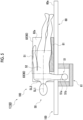
- Fig. 1 is a schematic view showing a particle beam treatment system 150 according to an embodiment of the present invention.
- the particle beam treatment system 150 is a system that treats a patient using a particle beam.
- the particle beam treatment system 150 includes a neutron capture therapy apparatus 1.
- the neutron capture therapy apparatus 1 is an apparatus that performs a cancer treatment using a boron neutron capture therapy (BNCT).
- BNCT boron neutron capture therapy
- the neutron capture therapy apparatus 1 includes a treatment section 102, a treatment bed 100 (placement section), and a moving mechanism 110.
- the treatment section 102 has an irradiation port 106 (irradiation section) that irradiates a patient 50 with a neutron ray N.
- the treatment section 102 is configured by a structure in which the irradiation port 106 or the moving mechanism 110 is disposed, and the like.
- the treatment section 102 is provided in a treatment room 101.
- the irradiation port 106 is provided on a vertical wall portion of the treatment room 101.
- the neutron ray N is emitted from the irradiation port 106 in a horizontal direction.
- the irradiation port 106 includes a collimator 20, which will be described later, and an irradiation section peripheral wall 115.
- the moving mechanism 110 is a mechanism capable of moving the treatment bed 100 on which the patient 50 is placed in the treatment section 102.
- the moving mechanism 110 is provided at a position in front of the irradiation port 106 in the treatment room 101.
- a tumor of the patient 50 to which boron ( 10 B) is administered is irradiated with the neutron ray N.
- the irradiation port 106 irradiates the patient 50 placed on a placement section 60 (see Fig. 3 ) of the treatment bed 100 with the neutron ray N (particle beam).
- the neutron capture therapy apparatus 1 includes an accelerator 2.
- the accelerator 2 accelerates particles to emit the particle beam R.
- a cyclotron, a linear accelerator, or the like may be adopted as the accelerator 2.
- the particle beam R emitted from the accelerator 2 passes through a transport path 9 called a beam duct, of which an inside is maintained in a vacuum and through which the beam can pass, and is transported to a target disposition section 30.
- the target disposition section 30 is a part where a target 10 is disposed, and has a mechanism that holds the target 10 in a posture for irradiation.
- the target disposition section 30 disposes the target 10 at a position facing an end portion (emission port) of the transport path 9.
- the particle beam R emitted from the accelerator 2 passes through the transport path 9 and advances toward the target 10 disposed at the end portion of the transport path 9.
- a plurality of electromagnets 4 (quadrupole electromagnets or the like) and a scanning electromagnet 6 are provided along the transport path 9.
- the plurality of electromagnets 4 perform, for example, beam axis adjustment of the particle beam R using the electromagnets.
- the scanning electromagnet 6 scans the particle beam R and controls the irradiation of the target 10 with the particle beam R.
- the scanning electromagnet 6 controls an irradiation position of the particle beam R with respect to the target 10.
- the neutron capture therapy apparatus 1 generates a neutron ray N by irradiating the target 10 with the particle beam R, and emits the neutron ray N toward the patient 50.
- the neutron capture therapy apparatus 1 includes the target 10, a shield member 8, a deceleration member 39, and the collimator 20.
- the target 10 generates the neutron ray N by being irradiated with the particle beam R.
- the target 10 is a solid shape member formed of a material that generates the neutron ray N by being irradiated with the particle beam R.
- the target 10 is formed of, for example, beryllium (Be), lithium (Li), tantalum (Ta), or tungsten (W), and has, for example, a solid shape in a disk shape having a diameter of 160 mm.
- the target 10 is not limited to the disk shape, and may have another shape.
- the deceleration member 39 decelerates the neutron ray N generated by the target 10 (reduces an energy of the neutron ray N).
- the deceleration member 39 may have a laminated structure including a layer 39A that mainly decelerates fast neutrons included in the neutron ray N and a layer 39B that mainly decelerates epithermal neutrons included in the neutron ray N.
- the shield member 8 shields the generated neutron ray N and gamma rays or the like generated with the generation of the neutron ray N from being released to the outside.
- the shield member 8 is provided to surround the deceleration member 39. An upper portion and a lower portion of the shield member 8 extend upstream of the particle beam R beyond the deceleration member 39.
- the collimator 20 shapes an irradiation field of the neutron ray N, and has an irradiation opening 20a through which the neutron ray N passes.
- the collimator 20 is, for example, a block-shaped member having the irradiation opening 20a at a center.
- the collimator 20 is attached to the irradiation section peripheral wall 115, which is a wall portion at a location where an inside of the treatment room 101 is irradiated with the neutron ray N.
- the moving mechanism 110 is a so-called six-axis mechanism that moves the treatment bed 100 on which the patient 50 is placed in six axial directions.
- the moving mechanism 110 allows the treatment bed 100 to move horizontally and to rotate.
- the moving mechanism 110 supports the patient 50 in a state of being placed on the treatment bed 100, and moves the patient 50 together with the treatment bed 100.
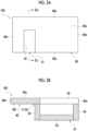
- Fig. 2A is a schematic plan view of the treatment bed 100.
- Fig. 2B is a schematic sectional view taken along line IIb-IIb shown in Fig. 2A .
- Fig. 3 is a schematic plan view showing the treatment bed 100 in a state of being loaded with the patient 50.
- Fig. 4 is a schematic sectional view showing the treatment bed 100 in the state of being loaded with the patient 50.
- Fig. 5 is a schematic side view showing the treatment bed 100 in the state of being loaded with the patient 50.
- the treatment bed 100 includes the placement section 60 and a support section 61.
- the placement section 60 is a member for placing the patient 50.
- the placement section 60 is a rectangular plate-shaped member.
- the placement section 60 has edge portions 60a and 60b on a long side and edge portions 60c and 60d on a short side.
- the placement section 60 has an upper surface 60e that is a placement surface on which the patient 50 is placed (see Fig. 3 ).
- the placement section 60 includes an arm passing portion 62 through which an arm 51 of the placed patient 50 passes (see also Figs. 4 and 5 ).
- the arm passing portion 62 is formed of a notch or a through-hole that penetrates the placement section 60 in an up-down direction.
- the arm passing portion 62 is configured by a cutout portion extending from the edge portion 60a on the long side to the edge portion 60b on the long side.
- the arm passing portion 62 is formed at a position closer to the edge portion 60c on the short side.
- the patient 50 placed on the upper surface 60e of the placement section 60 in a lateral position can extend the arm 51 on a placement section 60 side downward through the arm passing portion 62.
- the support section 61 supports the arm 51 passing through the arm passing portion 62 (see Figs. 4 and 5 ).
- the support section 61 has a bottom wall portion 63 parallel to the placement section 60 at a position separated downward from the arm passing portion 62.
- the support section 61 has a side wall portion 64 extending upward from an edge portion of the bottom wall portion 63.
- the patient 50 extends an upper arm 51a downward from the arm passing portion 62, bends an elbow, and places a forearm 51b on the bottom wall portion 63.
- the forearm 51b placed on the bottom wall portion 63 is protected by being surrounded by the side wall portion 64.
- the support section 61 has a maintenance structure 70 for maintaining a relative positional relationship with the placement section 60.
- maintaining the relative positional relationship means that a slight change in a relative position of the support section 61 with respect to the placement section 60 is allowed within a range in which a function as the support section 61 for supporting the arm 51 can be maintained, as well as in a state where the relative position of the support section 61 with respect to the placement section 60 is completely constant.
- the maintenance structure 70 allows not only complete synchronization between movement of the placement section 60 and movement of the support section 61, but also a slight deviation between the movements of the two.
- the maintenance structure 70 is configured by a connecting portion 71 of the support section 61 to the placement section 60.
- the connecting portion 71 connects an upper end portion of the side wall portion 64 and a lower surface 60f of the placement section 60. Accordingly, the support section 61 is fixed to the placement section 60. Therefore, when the placement section 60 moves, the support section 61 also moves in synchronization with the movement. In addition, the relative position of the support section 61 with respect to the placement section 60 remains completely constant.
- the maintenance structure 70 may adopt a configuration other than the connecting portion 71 to the placement section 60.
- the support section 61 may be separated from the placement section 60, and the support section 61 may be provided on a bogie that is movable on a floor surface. In this case, the connecting portion 71 is disposed below the arm passing portion 62 of the placement section 60.
- the particle beam treatment system 150 irradiates the patient 50 with the neutron ray N from the irradiation port 106 in a state where the patient 50 placed on the placement section 60 is fixed in the lateral position.
- the fixing here is to maintain a state of the lateral position such that the patient 50 does not maintain a posture by his/her own power during a treatment.
- a fixing force is not particularly limited, but it is preferable that the patient 50 can maintain a posture of the lateral position even when a force of about 10 N to 50 N is applied.
- the treatment bed 100 includes a support member 80 that supports the patient 50, and a pad member 81.
- the lateral position is a state where the patient 50 lies sideways with one of right and left arms of the patient 50 downward.
- An imaginary reference line SL1 extending in a longitudinal direction is set with respect to a torso 52 of the patient 50.
- an imaginary reference line SL2 that is perpendicular to the reference line SL1 and extends in a direction in which both right and left shoulders widen is set.
- An angle ⁇ of the reference line SL2 with respect to the upper surface 60e of the placement section 60 is defined when the patient 50 is set in the longitudinal direction (direction shown in Fig. 4 ).
- the lateral position applies not only in a case where the angle ⁇ is 90° but also when the angle ⁇ is within a range of 30° to 90° (rightward and leftward directions may be interchanged).
- the patient 50 twists his/her body, when the angle ⁇ in the vicinity of the shoulder is within the above range, the patient 50 is considered to be in the lateral position.
- the patient 50 is disposed such that the reference line SL1 is substantially perpendicular to an irradiating direction of the neutron ray N and extends along the horizontal direction. Therefore, the treatment bed 100 is disposed such that the longitudinal direction of the placement section 60 is substantially perpendicular to the irradiating direction of the neutron ray N and extends along the horizontal direction. In addition, the patient 50 is disposed such that a front side of the patient 50 faces the irradiation section peripheral wall 115. Here, a head or a neck area of the patient 50 is disposed in front of the irradiation port 106.
- the support member 80 is a member that supports the patient 50 placed on the placement section 60.
- the support member 80 includes a backrest member 82 and a belt-shaped member 83.
- the backrest member 82 is a member that stands upward from the upper surface 60e of the placement section 60.
- the backrest member 82 extends along the longitudinal direction of the placement section 60.
- the backrest member 82 supports a back of the torso 52 of the patient 50 on a support surface 82a.
- the support surface 82a may be made of a cushioning material. As shown in Fig.
- an angle of the backrest member 82 with respect to the placement section 60 is 90°. Accordingly, the backrest member 82 can support the posture of the lateral position of the patient 50 in a state of being in contact with the back of the patient 50. In a case where the angle ⁇ of the patient 50 is inclined with respect to the placement section 60, the angle of the backrest member 82 with respect to the placement section 60 is inclined with respect to the placement section 60 so as to be the same as the angle ⁇ of the patient 50 (see an imaginary line in Fig. 4 ).
- the belt-shaped member 83 is a member that can be wound around the patient 50.
- the belt-shaped member 83 is an elongated member having a predetermined width and extending in the longitudinal direction. In addition, the belt-shaped member 83 can be freely deformed at each portion.
- the belt-shaped member 83 is made of a fiber material or a resin material.
- a belt is adopted as the belt-shaped member 83. In Figs. 3 and 5 , the belt-shaped member 83 is shown by an imaginary line to show a state of the patient.
- the belt-shaped member 83 has a width dimension sufficient to cover substantially the entire torso 52 of the patient 50. In the present embodiment, one wide belt-shaped member 83 is used. However, a plurality of belt-shaped members 83 having a narrower width may be used.
- the belt-shaped member 83 is fixed in the vicinity of the edge portion 60a, wraps around upper ends of the patient 50 and the backrest member 82, and is fixed in the vicinity of the edge portion 60b.
- the belt-shaped member 83 wraps around the edge portions 60a and 60b up to a lower surface 60f side.
- the support member 80 has fulcrums 84a and 84b that hold end portions of the belt-shaped member 83 at a position of the lower surface 60f.
- the fulcrums 84a and 84b are disposed at positions lower than the upper surface 60e of the placement section 60.
- the belt-shaped member 83 draws a mountain shape, and supports the patient 50 with a supporting force F2 that presses the patient 50 downward against the placement section 60.
- the backrest member 82 applies a supporting force F1 to the torso 52 of the patient 50 in a direction perpendicular to the support surface 82a.
- the pad member 81 is a member that is interposed in a space between the patient 50 in the state of the lateral position and the placement section 60.
- the pad member 81 is disposed at a position corresponding to the torso 52 of the patient 50 on the upper surface 60e of the placement section 60.
- one shoulder and arm 51 are located on a lower side.
- the pad member 81 fills a space formed between the shoulder and the arm 51, and the torso 52.
- the pad member 81 may be made of a cushioning material.
- a procedure when the patient 50 is treated using the treatment bed 100 will be described with reference to Figs. 3 and 4 .
- the patient 50 is placed on the upper surface 60e of the placement section 60 of the treatment bed 100 in the state of the lateral position.
- the patient 50 places the torso 52 on the pad member 81 on the placement section 60.
- the patient 50 leans his/her back against the backrest member 82.
- the patient 50 passes the arm 51 on the lower side through the arm passing portion 62 and extends the arm 51 downward of the placement section 60.
- the elbow is bent, and the forearm 51b is placed on the bottom wall portion 63 of the support section 61.
- an IV drip 73 is inserted into the forearm 51b supported by the support section 61.
- a tube 74 of the IV drip 73 is drawn from the arm passing portion 62.
- the treatment bed 100 fixes the patient 50 with the inserted IV drip 73 by means of the belt-shaped member 83.
- the patient 50 is fixed by the support member 80 in a state of being in the lateral position. Accordingly, the head and neck area of the patient 50 can be disposed in front of a front surface of the collimator 20 of the irradiation port 106, and the posture can be maintained.
- the neutron capture therapy apparatus 1 irradiates an affected part of the patient 50 in a state of being fixed in the lateral position with the neutron ray N by emitting the neutron ray N from the collimator 20.
- a charged particle beam can be bent, it is easy to provide a mechanism for moving an irradiation opening with a gantry. Therefore, the irradiation opening can be disposed at a position corresponding to an affected part to be treated of a patient lying on his/her back on a treatment bed, by the gantry.
- the neutron capture therapy apparatus 1 the neutron ray N cannot be bent, and thus it is difficult to provide a moving mechanism such as a gantry. Therefore, a structure may be adopted in which the neutron ray N is emitted from the collimator 20 of the irradiation port 106 in the horizontal direction.
- the neutron capture therapy apparatus 1 since high-dose irradiation is performed, there is a possibility that a dose shortage may occur in a case where the irradiation is performed obliquely.
- the treatment site can be brought closest to an emission port of the neutron ray N in a case where the neutron ray N is irradiated from directly beside the patient 50 (at 90° with respect to the reference line SL1 of the torso 52). Therefore, in the present embodiment, the patient 50 is placed on the placement section 60 such that the reference line SL1 is substantially perpendicular to the irradiating direction of the neutron ray N (see Figs. 3 and 4 ).
- Fig. 6A is a plan view and a side view showing a state where the patient 50 is placed on the placement section 60 in the lateral position.
- Fig. 6B is a plan view and a side view showing a state where the patient 50 is placed on the placement section 60 in a supine position. As shown in Fig.
- the particle beam treatment system 150 includes the placement section 60 for placing the patient 50 to be irradiated with the particle beam. Therefore, the irradiation port 106 can irradiate the treatment site 55 of the patient 50 placed on the placement section 60 with the particle beam. With regard to this, the particle beam treatment system 150 irradiates the patient 50 with the particle beam from the irradiation port 106 in a state where the patient 50 placed on the placement section 60 is fixed in the lateral position. For example, as shown in Fig. 6A , when the patient 50 is in the lateral position, interference between the collimator 20 and the vicinity of the shoulder can be suppressed.
- the distance L1 between the emission port 20b and the treatment site 55 can be reduced.
- the treatment site 55 can be disposed near the emission port 20b of the irradiation port 106.
- the posture of the lateral position of the patient in a state where the treatment site 55 is disposed near the emission port 20b it is possible to suppress movement of the treatment site 55 during the treatment. Accordingly, the treatment can be reliably performed by performing accurate irradiation with the particle beam.
- the particle beam treatment system 150 may further include the support member 80 capable of supporting the patient 50 placed on the placement section 60 from at least one side with respect to the torso 52.
- the patient 50 can be easily fixed in the lateral position by using the support member 80.
- the support member 80 capable of supporting the patient 50 from at least one side with respect to the torso 52, the movement of the patient 50 is suppressed, and thus it is easy for the patient to maintain a comfortable posture.
- the support member 80 may include the belt-shaped member 83 that can be wound around the patient 50.
- the patient 50 can be fixed according to a physique or posture of the patient 50 by using the belt-shaped member 83.
- the particle beam treatment system 150 may further include the pad member 81 interposed in a space between the patient 50 in the state of the lateral position and the placement section 60. Accordingly, a space between the arm and the shoulder of the patient 50 in the state of the lateral position, the torso 52, and the placement section 60 can be filled with the pad member 81. Therefore, even in a case where the patient 50 is in the lateral position with one arm and shoulder placed on the lower side, the movement of the patient 50 is suppressed, and it is easy for the patient 50 to maintain a comfortable posture.
- the particle beam treatment system 150 may include the neutron capture therapy apparatus 1.
- the neutron capture therapy apparatus 1 since it is necessary to perform high-dose irradiation, it is highly necessary to bring the treatment site 55 of the patient 50 close to the emission port 20b of the irradiation port 106. Therefore, compared to a proton beam treatment or the like, the patient 50 is more likely to be in a posture that is burdensome for the patient 50, such as a lateral position. Furthermore, since an irradiation time is long, a time for which the burden is applied to the patient 50 increases. Therefore, by adopting the structure of the present embodiment for the neutron capture therapy apparatus 1, it is possible to suppress the burden on the patient 50 and to perform accurate irradiation with the neutron ray N.
- the support member 80 for a particle beam treatment is the support member 80 for a particle beam treatment that supports the patient 50 to be irradiated with the particle beam, and is capable of fixing the patient 50 placed on the placement section 60 in the state of the lateral position.
- the support member 80 for a particle beam treatment can fix the patient 50 placed on the placement section 60 in the state of the lateral position. Therefore, by placing the patient 50 in the lateral position using the support member 80 according to the position of the treatment site 55 of the patient 50, the treatment site 55 can be disposed near the emission port 20b. Furthermore, a state where the posture of the lateral position of the patient 50 is fixed by the support member 80 can be maintained in a state where the treatment site 55 is disposed near the emission port 20b, so that it is possible to suppress the movement of the treatment site 55 during the treatment. Accordingly, the treatment can be reliably performed by performing accurate irradiation with the particle beam.
- the present invention is not limited to the above-described embodiment.
- a support unit 120 as shown in Figs. 7A to 7C may be adopted.
- the support unit 120 is unitized by a backrest member 182 (first member), a belt-shaped member 183 (second member), and a pad member 181.
- the belt-shaped member 183 is attached to the backrest member 182.
- an angle between the backrest member 182 and the belt-shaped member 183, and the pad member 181 is set according to the angle ⁇ (see Fig. 4 ) with respect to the placement section 60 of the patient 50.
- Fig. 7A is a perspective view showing the support unit 120 in which the backrest member 182 is set at 90° with respect to the placement section 60.
- FIG. 7B is a perspective view showing the support unit 120 in which the backrest member 182 is set at 60° with respect to the placement section 60.
- Fig. 7C is a perspective view showing the support unit 120 in which the backrest member 182 is set at 45° with respect to the placement section 60.
- the backrest member 182 and the belt-shaped member 183 may be capable of adjusting the angle with respect to the pad member 181 (that is, the placement section 60). That is, the angle of the backrest member 182 and the belt-shaped member 183 can be changed according to the angle ⁇ of the patient 50 with respect to the placement section 60.
- the angle of the backrest member 182 and the belt-shaped member 183 with respect to the pad member 181 (that is, the placement section 60) may be fixed and non-adjustable.
- a plurality of support units 120 may be prepared according to the angle ⁇ of the patient 50 with respect to the placement section 60.
- FIG. 8 is a view of the support unit 120 as viewed in the longitudinal direction. As shown in Fig. 8 , one end portion of the pad member 181 and a lower end portion of the backrest member 182 are connected to each other via a connecting portion 185. In a case where the angle of the backrest member 182 is adjustable, a hinge mechanism that rotatably supports the backrest member 182 relative to the pad member 181 and locks the backrest member 182 at a desired angle is provided in the connecting portion 185.
- One end portion of the belt-shaped member 183 is held on a lower end side of the backrest member 182, and the other end portion thereof is held on an upper end side of the backrest member 182.
- One end portion of the belt-shaped member 183 wraps around a back side from the lower end side of the backrest member 182 and is held at a fulcrum 184b.
- the other end portion of the belt-shaped member 183 wraps around the back side from the upper end side of the backrest member 182 and is held at a fulcrum 184a.
- Both of the fulcrums 184a and 184b are disposed at positions higher than the placement section 60.
- the support member 80 of the support unit 120 can support the patient 50 placed on the placement section 60 from both sides with respect to the torso 52.
- the belt-shaped member 183 is wound around the torso 52 of the patient 50 placed on the pad member 181 in a state of a lateral position (see Fig. 7A ). Since the belt-shaped member 183 is held at the fulcrums 184a and 184b on the upper end side and the lower end side of the backrest member 182, a supporting force F3 is applied by tightening the belt-shaped member 183 so as to press the backrest member 182 against the patient 50. As a repulsive force, a supporting force F1 is applied to the patient 50 from the backrest member 182. In this way, by supporting the patient 50 from both sides with respect to the torso 52, the movement of the patient 50 is suppressed, and thus it is easy for the patient 50 to maintain a comfortable posture.
- the state of being supported from both sides with respect to the torso 52 is a state where the support member 80 can apply a supporting force to the torso 52 of the patient 50 in at least two directions, and the supporting forces act in opposite directions across the torso 52.
- the supporting forces in the two directions act in a direction perpendicular to the longitudinal direction of the placement section 60 and extending along the upper surface of the placement section 60.
- the supporting force F2 of the belt-shaped member 83 is directed downward, and does not act in the opposite direction to the supporting force F1 of the backrest member 82. Therefore, the form does not correspond to the state of being supported from both sides with respect to the torso 52.
- the support member 80 has the fulcrum 184a that holds one end portion of the belt-shaped member 83, and the fulcrum 184a is disposed at a position higher than the placement section 60.
- the belt-shaped member 83 applies a supporting force to press the patient toward a placement section side.
- the fulcrum 184a is disposed at a position higher than the placement section 60, it is possible to apply a supporting force in a direction other than the direction in which the placement section 60 is pressed. Accordingly, it is easy to apply supporting forces to the patient 50 from both sides with respect to the torso 52 of the patient 50.
- the support member 80 has the backrest member 182 (first member) and the belt-shaped member 183 (second member) that support the patient 50 placed on the placement section 60 from both sides with respect to the torso 52.
- the support member 80 unitized by the backrest member 182 (first member) and the belt-shaped member 183 (second member), it is possible to easily position and fix the patient 50.
- Figs. 9A to 10 Structures as shown in Figs. 9A to 10 may be adopted.
- a form shown in Figs. 9A and 9B one end portion of the belt-shaped member 83 is held at the fulcrum 84b on an upper end side of the backrest member 82.
- the belt-shaped member 83 is wrapped around an upper end of the backrest member 82 from the fulcrum 84b and is lowered downward to be disposed on the placement section 60. In this state, the patient 50 is disposed on the belt-shaped member 83 disposed on the placement section 60.
- the belt-shaped member 83 is wound around the torso 52 of the patient 50, and the other end portion of the belt-shaped member is wrapped around the upper end of the backrest member 82 and pulled toward a lower surface side of the placement section 60. Then, the other end portion of the belt-shaped member 83 is held at the fulcrum 84a on the lower surface of the placement section 60 in a state where a tension is applied so that the patient 50 is tightened.
- the belt-shaped member 83 is wrapped around a lower side of the torso 52 from a side surface of the torso 52 on one side in the horizontal direction, and is wound to be wrapped around a side surface of the torso 52 on the other side in the horizontal direction.
- a gap is provided between the belt-shaped member 83 and other members and the patient 50 in order to facilitate understanding of the state of the belt-shaped member 83.
- the belt-shaped member 83 is in contact with other members and the patient 50 without any gaps. The same applies to Fig. 10 described later.
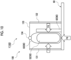
- the patient 50 may be hung by the belt-shaped member 83.
- the placement section 60 is provided with pillar members 131 and 132 on both sides of the backrest member 82, and a wire 133 is provided between the upper ends of the pillar members 131 and 132.
- the wire 133 is provided with a fulcrum 134 that holds both end portions of the belt-shaped member 83.
- the belt-shaped member 83 In a state where the belt-shaped member 83 is wound around the torso 52 of the patient 50, the belt-shaped member 83 together with the patient 50 is hung at the fulcrum 134.
- the torso 52 of the patient 50 is tightened by the belt-shaped member 83 due to an action of gravity. Accordingly, the supporting forces F4 and F5 in opposite directions are applied to the torso 52 of the patient 50 from both sides in the horizontal direction, and the supporting force F6 directed upward from the lower side is applied.
- the support member 80 shown in Figs. 9A to 10 can apply the supporting forces to the torso 52 from the lower side and from both sides in the horizontal direction by winding the belt-shaped member 83 around the torso 52 of the patient 50 placed on the placement section 60.
- the supporting forces in multiple directions according to the physique and posture of the patient 50 by using the belt-shaped member 83, the movement of the patient 50 is suppressed, and thus it is easy for the patient to maintain a comfortable posture.
- the supporting force F2 since the supporting force F2 is applied to press the patient 50 against the placement section 60, there may be a burden on the shoulder or the like of the patient 50. Contrary to this, in Figs.
- the support member 80 has the fulcrums 84b and 134 for holding one end portion of the belt-shaped member 83, and the fulcrums 84b and 134 are disposed at positions higher than the placement section 60.
- the fulcrums 84b and 134 are disposed at positions higher than the placement section 60, it is possible to apply a supporting force in a direction other than the direction in which the placement section 60 is pressed as shown in Fig. 4 . Accordingly, it is easy to apply supporting forces to the patient 50 from both sides with respect to the torso 52 of the patient 50.
- the support member for the neutron capture therapy apparatus has been exemplified.
- a treatment apparatus included in the particle beam treatment system is not particularly limited, and a wide range of treatment apparatuses using a particle beam such as a proton beam treatment apparatus, a heavy particle beam apparatus, or an X-ray device can be applied.
Landscapes
- Health & Medical Sciences (AREA)
- Engineering & Computer Science (AREA)
- Biomedical Technology (AREA)
- Pathology (AREA)
- Nuclear Medicine, Radiotherapy & Molecular Imaging (AREA)
- Radiology & Medical Imaging (AREA)
- Life Sciences & Earth Sciences (AREA)
- Animal Behavior & Ethology (AREA)
- General Health & Medical Sciences (AREA)
- Public Health (AREA)
- Veterinary Medicine (AREA)
- Radiation-Therapy Devices (AREA)
Abstract
Provided are a particle beam treatment system (150) capable of performing accurate irradiation with a particle beam and a support member (80) for a particle beam treatment. A particle beam treatment system (150) includes a placement section (60) for placing a patient (50) to be irradiated with a particle beam. Therefore, an irradiation port (106) can irradiate a treatment site (55) of the patient (50) placed on the placement section (60) with the particle beam. With regard to this, the particle beam treatment system (150) irradiates the patient (50) with the particle beam from the irradiation port (106) in a state where the patient (50) placed on the placement section (60) is fixed in the lateral position. For example, as shown in Fig. 6A, when the patient (50) is in the lateral position, interference between the collimator (20) and the vicinity of a shoulder can be suppressed. Therefore, a distance (L1) between an emission port (20b) and the treatment site (55) can be reduced. In this way, by placing the patient (50) in the lateral position according to a position of the treatment site (55) of the patient (50), the treatment site (55) can be disposed near the emission port (20b) of the irradiation port (106). Furthermore, by fixing a posture of the lateral position of the patient in a state where the treatment site (55) is disposed near the emission port (20b), it is possible to suppress movement of the treatment site (55) during a treatment.
Description
- The present invention relates to a particle beam treatment system and a support member for a particle beam treatment.
- A technology for performing a treatment by irradiating a patient with a particle beam is known (for example,
Japanese Unexamined Patent Publication No. 2016-83351 Japanese Unexamined Patent Publication No. 2016-83351 - In
Japanese Unexamined Patent Publication No. 2016-83351 - Here, when the treatment is performed by irradiation with the particle beam, there are cases where it is preferable to place the patient in a state of a lateral position depending on a position of an affected part. However, since the lateral position is a burdensome posture for the patient, it is difficult to maintain the posture, and thus there is a problem in that it is difficult to accurately irradiate the affected part with the particle beam.
- Therefore, an object of the present invention is to provide a particle beam treatment system capable of performing accurate irradiation with a particle beam and a support member for a particle beam treatment.
- A particle beam treatment system according to the present invention includes: a placement section for placing a patient to be irradiated with a particle beam; and an irradiation section that irradiates the patient placed on the placement section with the particle beam, wherein the irradiation section irradiates the patient with the particle beam in a state where the patient placed on the placement section is fixed in a lateral position.
- The particle beam treatment system according to the present invention includes the placement section for placing the patient to be irradiated with the particle beam. Therefore, the irradiation section can irradiate a treatment site of the patient placed on the placement section with the particle beam. With regard to this, the particle beam treatment system irradiates the patient with the particle beam from the irradiation section in a state where the patient placed on the placement section is fixed in the lateral position. By placing the patient in a lateral position according to the position of the treatment site of the patient, the treatment site can be disposed close to the irradiator. Furthermore, by fixing a posture of the lateral position of the patient in a state where the treatment site is disposed near the irradiation section, it is possible to suppress movement of the treatment site during a treatment. Accordingly, the treatment can be reliably performed by performing accurate irradiation with the particle beam.
- The particle beam treatment system may further include: a support member that is capable of supporting the patient placed on the placement section from at least one side with respect to a torso of the patient. The patient can be easily fixed in the lateral position by using the support member. In addition, by supporting the patient from at least one side with respect to the torso, the movement of the patient is suppressed, and thus it is easy for the patient to maintain a comfortable posture.
- The support member may be capable of supporting the patient placed on the placement section from both sides with respect to the torso. In this way, by supporting the patient from both sides with respect to the torso, the movement of the patient is suppressed, and thus it is easy for the patient to maintain a comfortable posture.
- The support member may include a belt-shaped member that is windable around the patient. The patient can be fixed according to a physique or posture of the patient by using the belt-shaped member.
- The support member may include a fulcrum that holds one end portion of the belt-shaped member, and the fulcrum may be disposed at a position higher than the placement section. For example, in a case where the fulcrums of both end portions of the belt-shaped member are located at positions lower than the placement section, the belt-shaped member applies a supporting force to press the patient toward a placement section side. Contrary to this, in a case where the fulcrum is disposed at a position higher than the placement section, it is possible to apply a supporting force in a direction other than the direction in which the placement section is pressed. Accordingly, it is easy to apply supporting forces to the patient from both sides with respect to the torso of the patient.
- The support member may apply a supporting force to the torso from below and from both sides in a horizontal direction by winding the belt-shaped member around the torso of the patient placed on the placement section. In this case, by applying the supporting forces in multiple directions according to the physique and posture of the patient by using the belt-shaped member, the movement of the patient is suppressed, and thus it is easy for the patient to maintain a comfortable posture.
- The support member may include a first member that supports the patient placed on the placement section from both sides with respect to the torso, and a second member. By using the support member unitized by the first member and the second member, it is possible to easily position and fix the patient.
- The particle beam treatment system may further include: a pad member interposed in a space between the patient in a state of the lateral position and the placement section. Accordingly, a space between an arm and shoulder of the patient in the state of the lateral position, the torso, and the placement section can be filled with the pad member. Therefore, even in a case where the patient is in the lateral position with one arm and shoulder placed on a lower side, the movement of the patient is suppressed, and it is easy for the patient to maintain a comfortable posture.
- The particle beam treatment system may further include a neutron capture therapy apparatus. In the case of the neutron capture therapy apparatus, since it is necessary to perform high-dose irradiation, it is highly necessary to bring the treatment site of the patient close to the irradiation section. Therefore, compared to a proton beam treatment or the like, the patient is more likely to be in a posture that is burdensome for the patient, such as a lateral position. Furthermore, since an irradiation time is long, a time for which the burden is applied to the patient increases. Therefore, by adopting a structure of the present invention for the neutron capture therapy apparatus, it is possible to suppress the burden on the patient and to perform accurate irradiation with a neutron ray.
- A support member for a particle beam treatment according to the present invention is a support member for a particle beam treatment that supports a patient to be irradiated with a particle beam, in which the support member for a particle beam treatment is capable of fixing the patient placed on a placement section in a state of a lateral position.
- The support member for a particle beam treatment according to the present invention can fix the patient placed on the placement section in the state of the lateral position. Therefore, by placing the patient in the lateral position using the support member according to the position of the treatment site of the patient, the treatment site can be disposed near the irradiation section. Furthermore, a state where the posture of the lateral position of the patient is fixed by the support member can be maintained in a state where the treatment site is disposed near the irradiation section, so that it is possible to suppress the movement of the treatment site during the treatment. Accordingly, the treatment can be reliably performed by performing accurate irradiation with the particle beam.
- According to the present invention, it is possible to provide a particle beam treatment system capable of performing accurate irradiation with a particle beam and a support member for a particle beam treatment.
-
-
Fig. 1 is a schematic view showing a particle beam treatment system according to an embodiment of the present invention. -
Fig. 2A is a schematic plan view of a treatment bed, andFig. 2B is a schematic sectional view taken along line IIb-IIb shown inFig. 2A . -
Fig. 3 is a schematic plan view showing the treatment bed in a state of being loaded with a patient. -
Fig. 4 is a schematic sectional view showing the treatment bed in the state of being loaded with the patient. -
Fig. 5 is a schematic side view showing the treatment bed in the state of being loaded with the patient. -
Figs. 6A and 6B are schematic views for describing a positional relationship between an emission port and a treatment site. -
Figs. 7A to 7C are views showing a support member of a particle beam treatment system according to a modification example. -
Fig. 8 is a view showing a support member of a particle beam treatment system according to a modification example. -
Figs. 9A and 9B are views showing a support member of a particle beam treatment system according to a modification example. -
Fig. 10 is a view illustrating a support member of a particle beam treatment system according to a modification example. - Hereinafter, a preferred embodiment of the present invention will be described in detail with reference to the accompanying drawings.
-
Fig. 1 is a schematic view showing a particlebeam treatment system 150 according to an embodiment of the present invention. The particlebeam treatment system 150 is a system that treats a patient using a particle beam. The particlebeam treatment system 150 includes a neutroncapture therapy apparatus 1. The neutroncapture therapy apparatus 1 is an apparatus that performs a cancer treatment using a boron neutron capture therapy (BNCT). The neutroncapture therapy apparatus 1 includes atreatment section 102, a treatment bed 100 (placement section), and a movingmechanism 110. - The
treatment section 102 has an irradiation port 106 (irradiation section) that irradiates a patient 50 with a neutron ray N. Thetreatment section 102 is configured by a structure in which theirradiation port 106 or the movingmechanism 110 is disposed, and the like. Thetreatment section 102 is provided in atreatment room 101. Theirradiation port 106 is provided on a vertical wall portion of thetreatment room 101. The neutron ray N is emitted from theirradiation port 106 in a horizontal direction. Theirradiation port 106 includes acollimator 20, which will be described later, and an irradiation sectionperipheral wall 115. The movingmechanism 110 is a mechanism capable of moving thetreatment bed 100 on which thepatient 50 is placed in thetreatment section 102. The movingmechanism 110 is provided at a position in front of theirradiation port 106 in thetreatment room 101. - In the
treatment section 102, for example, a tumor of the patient 50 to which boron (10B) is administered is irradiated with the neutron ray N. Theirradiation port 106 irradiates the patient 50 placed on a placement section 60 (seeFig. 3 ) of thetreatment bed 100 with the neutron ray N (particle beam). - The neutron
capture therapy apparatus 1 includes anaccelerator 2. Theaccelerator 2 accelerates particles to emit the particle beam R. For example, a cyclotron, a linear accelerator, or the like may be adopted as theaccelerator 2. - The particle beam R emitted from the
accelerator 2 passes through atransport path 9 called a beam duct, of which an inside is maintained in a vacuum and through which the beam can pass, and is transported to atarget disposition section 30. Thetarget disposition section 30 is a part where atarget 10 is disposed, and has a mechanism that holds thetarget 10 in a posture for irradiation. Thetarget disposition section 30 disposes thetarget 10 at a position facing an end portion (emission port) of thetransport path 9. The particle beam R emitted from theaccelerator 2 passes through thetransport path 9 and advances toward thetarget 10 disposed at the end portion of thetransport path 9. A plurality of electromagnets 4 (quadrupole electromagnets or the like) and ascanning electromagnet 6 are provided along thetransport path 9. The plurality ofelectromagnets 4 perform, for example, beam axis adjustment of the particle beam R using the electromagnets. - The
scanning electromagnet 6 scans the particle beam R and controls the irradiation of thetarget 10 with the particle beam R. Thescanning electromagnet 6 controls an irradiation position of the particle beam R with respect to thetarget 10. - The neutron
capture therapy apparatus 1 generates a neutron ray N by irradiating thetarget 10 with the particle beam R, and emits the neutron ray N toward thepatient 50. The neutroncapture therapy apparatus 1 includes thetarget 10, ashield member 8, adeceleration member 39, and thecollimator 20. - The
target 10 generates the neutron ray N by being irradiated with the particle beam R. Thetarget 10 is a solid shape member formed of a material that generates the neutron ray N by being irradiated with the particle beam R. Specifically, thetarget 10 is formed of, for example, beryllium (Be), lithium (Li), tantalum (Ta), or tungsten (W), and has, for example, a solid shape in a disk shape having a diameter of 160 mm. Thetarget 10 is not limited to the disk shape, and may have another shape. - The
deceleration member 39 decelerates the neutron ray N generated by the target 10 (reduces an energy of the neutron ray N). Thedeceleration member 39 may have a laminated structure including alayer 39A that mainly decelerates fast neutrons included in the neutron ray N and alayer 39B that mainly decelerates epithermal neutrons included in the neutron ray N. - The
shield member 8 shields the generated neutron ray N and gamma rays or the like generated with the generation of the neutron ray N from being released to the outside. Theshield member 8 is provided to surround thedeceleration member 39. An upper portion and a lower portion of theshield member 8 extend upstream of the particle beam R beyond thedeceleration member 39. - The
collimator 20 shapes an irradiation field of the neutron ray N, and has anirradiation opening 20a through which the neutron ray N passes. Thecollimator 20 is, for example, a block-shaped member having theirradiation opening 20a at a center. Thecollimator 20 is attached to the irradiation sectionperipheral wall 115, which is a wall portion at a location where an inside of thetreatment room 101 is irradiated with the neutron ray N. - The moving
mechanism 110 is a so-called six-axis mechanism that moves thetreatment bed 100 on which thepatient 50 is placed in six axial directions. The movingmechanism 110 allows thetreatment bed 100 to move horizontally and to rotate. In the present embodiment, the movingmechanism 110 supports the patient 50 in a state of being placed on thetreatment bed 100, and moves the patient 50 together with thetreatment bed 100. - Next, a detailed configuration of the
treatment bed 100 will be described with reference toFigs. 2A to 5 .Fig. 2A is a schematic plan view of thetreatment bed 100.Fig. 2B is a schematic sectional view taken along line IIb-IIb shown inFig. 2A .Fig. 3 is a schematic plan view showing thetreatment bed 100 in a state of being loaded with thepatient 50.Fig. 4 is a schematic sectional view showing thetreatment bed 100 in the state of being loaded with thepatient 50.Fig. 5 is a schematic side view showing thetreatment bed 100 in the state of being loaded with thepatient 50. - As shown in
Figs. 2A and 2B , thetreatment bed 100 includes theplacement section 60 and asupport section 61. Theplacement section 60 is a member for placing thepatient 50. Theplacement section 60 is a rectangular plate-shaped member. Theplacement section 60 hasedge portions edge portions placement section 60 has anupper surface 60e that is a placement surface on which thepatient 50 is placed (seeFig. 3 ). - As shown in
Fig. 2A , theplacement section 60 includes anarm passing portion 62 through which anarm 51 of the placedpatient 50 passes (see alsoFigs. 4 and5 ). Thearm passing portion 62 is formed of a notch or a through-hole that penetrates theplacement section 60 in an up-down direction. In the present embodiment, thearm passing portion 62 is configured by a cutout portion extending from theedge portion 60a on the long side to theedge portion 60b on the long side. Thearm passing portion 62 is formed at a position closer to theedge portion 60c on the short side. As shown inFigs. 3 and4 , the patient 50 placed on theupper surface 60e of theplacement section 60 in a lateral position can extend thearm 51 on aplacement section 60 side downward through thearm passing portion 62. - As shown in
Fig. 2B , thesupport section 61 supports thearm 51 passing through the arm passing portion 62 (seeFigs. 4 and5 ). Thesupport section 61 has abottom wall portion 63 parallel to theplacement section 60 at a position separated downward from thearm passing portion 62. In addition, thesupport section 61 has aside wall portion 64 extending upward from an edge portion of thebottom wall portion 63. As shown inFig. 4 , thepatient 50 extends anupper arm 51a downward from thearm passing portion 62, bends an elbow, and places aforearm 51b on thebottom wall portion 63. In addition, theforearm 51b placed on thebottom wall portion 63 is protected by being surrounded by theside wall portion 64. - The
support section 61 has amaintenance structure 70 for maintaining a relative positional relationship with theplacement section 60. Here, maintaining the relative positional relationship means that a slight change in a relative position of thesupport section 61 with respect to theplacement section 60 is allowed within a range in which a function as thesupport section 61 for supporting thearm 51 can be maintained, as well as in a state where the relative position of thesupport section 61 with respect to theplacement section 60 is completely constant. In addition, themaintenance structure 70 allows not only complete synchronization between movement of theplacement section 60 and movement of thesupport section 61, but also a slight deviation between the movements of the two. - In the present embodiment, the
maintenance structure 70 is configured by a connectingportion 71 of thesupport section 61 to theplacement section 60. The connectingportion 71 connects an upper end portion of theside wall portion 64 and alower surface 60f of theplacement section 60. Accordingly, thesupport section 61 is fixed to theplacement section 60. Therefore, when theplacement section 60 moves, thesupport section 61 also moves in synchronization with the movement. In addition, the relative position of thesupport section 61 with respect to theplacement section 60 remains completely constant. Themaintenance structure 70 may adopt a configuration other than the connectingportion 71 to theplacement section 60. For example, thesupport section 61 may be separated from theplacement section 60, and thesupport section 61 may be provided on a bogie that is movable on a floor surface. In this case, the connectingportion 71 is disposed below thearm passing portion 62 of theplacement section 60. - Next, states of the patient 50 on the
treatment bed 100 will be described with reference toFigs. 3 to 5 . The particlebeam treatment system 150 irradiates the patient 50 with the neutron ray N from theirradiation port 106 in a state where the patient 50 placed on theplacement section 60 is fixed in the lateral position. The fixing here is to maintain a state of the lateral position such that thepatient 50 does not maintain a posture by his/her own power during a treatment. A fixing force is not particularly limited, but it is preferable that the patient 50 can maintain a posture of the lateral position even when a force of about 10 N to 50 N is applied. Thetreatment bed 100 includes asupport member 80 that supports thepatient 50, and apad member 81. - Here, the state of the lateral position of the patient 50 will be described. The lateral position is a state where the patient 50 lies sideways with one of right and left arms of the patient 50 downward. An imaginary reference line SL1 extending in a longitudinal direction is set with respect to a
torso 52 of thepatient 50. In addition, an imaginary reference line SL2 that is perpendicular to the reference line SL1 and extends in a direction in which both right and left shoulders widen is set. An angle θ of the reference line SL2 with respect to theupper surface 60e of theplacement section 60 is defined when thepatient 50 is set in the longitudinal direction (direction shown inFig. 4 ). The lateral position applies not only in a case where the angle θ is 90° but also when the angle θ is within a range of 30° to 90° (rightward and leftward directions may be interchanged). In addition, even in a case where the patient 50 twists his/her body, when the angle θ in the vicinity of the shoulder is within the above range, thepatient 50 is considered to be in the lateral position. - In the present embodiment, the
patient 50 is disposed such that the reference line SL1 is substantially perpendicular to an irradiating direction of the neutron ray N and extends along the horizontal direction. Therefore, thetreatment bed 100 is disposed such that the longitudinal direction of theplacement section 60 is substantially perpendicular to the irradiating direction of the neutron ray N and extends along the horizontal direction. In addition, thepatient 50 is disposed such that a front side of the patient 50 faces the irradiation sectionperipheral wall 115. Here, a head or a neck area of thepatient 50 is disposed in front of theirradiation port 106. - The
support member 80 is a member that supports the patient 50 placed on theplacement section 60. In the present embodiment, thesupport member 80 includes abackrest member 82 and a belt-shapedmember 83. Thebackrest member 82 is a member that stands upward from theupper surface 60e of theplacement section 60. Thebackrest member 82 extends along the longitudinal direction of theplacement section 60. Thebackrest member 82 supports a back of thetorso 52 of the patient 50 on asupport surface 82a. Thesupport surface 82a may be made of a cushioning material. As shown inFig. 4 , in a case where the angle θ of the reference line SL2 of the patient 50 with respect to theplacement section 60 is 90°, an angle of thebackrest member 82 with respect to theplacement section 60 is 90°. Accordingly, thebackrest member 82 can support the posture of the lateral position of the patient 50 in a state of being in contact with the back of thepatient 50. In a case where the angle θ of thepatient 50 is inclined with respect to theplacement section 60, the angle of thebackrest member 82 with respect to theplacement section 60 is inclined with respect to theplacement section 60 so as to be the same as the angle θ of the patient 50 (see an imaginary line inFig. 4 ). - The belt-shaped
member 83 is a member that can be wound around thepatient 50. The belt-shapedmember 83 is an elongated member having a predetermined width and extending in the longitudinal direction. In addition, the belt-shapedmember 83 can be freely deformed at each portion. The belt-shapedmember 83 is made of a fiber material or a resin material. A belt is adopted as the belt-shapedmember 83. InFigs. 3 and5 , the belt-shapedmember 83 is shown by an imaginary line to show a state of the patient. In the present embodiment, the belt-shapedmember 83 has a width dimension sufficient to cover substantially theentire torso 52 of thepatient 50. In the present embodiment, one wide belt-shapedmember 83 is used. However, a plurality of belt-shapedmembers 83 having a narrower width may be used. - As shown in
Fig. 4 , the belt-shapedmember 83 is fixed in the vicinity of theedge portion 60a, wraps around upper ends of thepatient 50 and thebackrest member 82, and is fixed in the vicinity of theedge portion 60b. The belt-shapedmember 83 wraps around theedge portions lower surface 60f side. Thesupport member 80 hasfulcrums member 83 at a position of thelower surface 60f. In the present embodiment, thefulcrums upper surface 60e of theplacement section 60. Accordingly, the belt-shapedmember 83 draws a mountain shape, and supports the patient 50 with a supporting force F2 that presses the patient 50 downward against theplacement section 60. In addition, thebackrest member 82 applies a supporting force F1 to thetorso 52 of the patient 50 in a direction perpendicular to thesupport surface 82a. - The
pad member 81 is a member that is interposed in a space between the patient 50 in the state of the lateral position and theplacement section 60. Thepad member 81 is disposed at a position corresponding to thetorso 52 of the patient 50 on theupper surface 60e of theplacement section 60. When thepatient 50 is in the posture of the lateral position on theplacement section 60, one shoulder andarm 51 are located on a lower side. Thepad member 81 fills a space formed between the shoulder and thearm 51, and thetorso 52. Thepad member 81 may be made of a cushioning material. - Next, a procedure when the
patient 50 is treated using thetreatment bed 100 will be described with reference toFigs. 3 and4 . As shown inFigs. 3 and4 , first, thepatient 50 is placed on theupper surface 60e of theplacement section 60 of thetreatment bed 100 in the state of the lateral position. The patient 50 places thetorso 52 on thepad member 81 on theplacement section 60. In addition, thepatient 50 leans his/her back against thebackrest member 82. The patient 50 passes thearm 51 on the lower side through thearm passing portion 62 and extends thearm 51 downward of theplacement section 60. In addition, the elbow is bent, and theforearm 51b is placed on thebottom wall portion 63 of thesupport section 61. Next, anIV drip 73 is inserted into theforearm 51b supported by thesupport section 61. Atube 74 of theIV drip 73 is drawn from thearm passing portion 62. Thetreatment bed 100 fixes the patient 50 with the insertedIV drip 73 by means of the belt-shapedmember 83. - In this way, the
patient 50 is fixed by thesupport member 80 in a state of being in the lateral position. Accordingly, the head and neck area of the patient 50 can be disposed in front of a front surface of thecollimator 20 of theirradiation port 106, and the posture can be maintained. The neutroncapture therapy apparatus 1 irradiates an affected part of the patient 50 in a state of being fixed in the lateral position with the neutron ray N by emitting the neutron ray N from thecollimator 20. - Next, operation and effects of the particle
beam treatment system 150 according to the present embodiment will be described. - For example, in a proton beam treatment apparatus, since a charged particle beam can be bent, it is easy to provide a mechanism for moving an irradiation opening with a gantry. Therefore, the irradiation opening can be disposed at a position corresponding to an affected part to be treated of a patient lying on his/her back on a treatment bed, by the gantry. On the other hand, in the case of the neutron
capture therapy apparatus 1, the neutron ray N cannot be bent, and thus it is difficult to provide a moving mechanism such as a gantry. Therefore, a structure may be adopted in which the neutron ray N is emitted from thecollimator 20 of theirradiation port 106 in the horizontal direction. In an apparatus that performs emission in the horizontal direction from theirradiation port 106 as described above, in a case where a treatment site near a clavicle of thepatient 50 is irradiated with the neutron ray N, it is conceivable to irradiate the treatment site obliquely in consideration of a burden on thepatient 50. In a case of irradiating a cervical region (neck), an irradiating direction is changed depending on a position of the affected part in the neck. In such a case, it may be better to irradiate the treatment site obliquely even without considering the burden on thepatient 50. However, in the case of the neutroncapture therapy apparatus 1, since high-dose irradiation is performed, there is a possibility that a dose shortage may occur in a case where the irradiation is performed obliquely. The treatment site can be brought closest to an emission port of the neutron ray N in a case where the neutron ray N is irradiated from directly beside the patient 50 (at 90° with respect to the reference line SL1 of the torso 52). Therefore, in the present embodiment, thepatient 50 is placed on theplacement section 60 such that the reference line SL1 is substantially perpendicular to the irradiating direction of the neutron ray N (seeFigs. 3 and4 ). - Here, a distance between a
treatment site 55 of thepatient 50 and anemission port 20b of thecollimator 20 will be described with reference toFigs. 6A and 6B. Fig. 6A is a plan view and a side view showing a state where thepatient 50 is placed on theplacement section 60 in the lateral position.Fig. 6B is a plan view and a side view showing a state where thepatient 50 is placed on theplacement section 60 in a supine position. As shown inFig. 6B , in a case where thetreatment site 55 is present near the clavicle, even if theemission port 20b is brought close to thetreatment site 55, thecollimator 20 and the vicinity of the shoulder of the patient 50 interfere with each other, and thus a distance L1 between theemission port 20b and thetreatment site 55 increases. Such a problem is particularly likely to occur when a portion smaller than thetorso 52 such as the neck or chin as well as the clavicle is irradiated with the neutron ray N in a direction intersecting the reference line SL1 of thepatient 50. - In response to such a problem, the particle
beam treatment system 150 according to the present embodiment includes theplacement section 60 for placing the patient 50 to be irradiated with the particle beam. Therefore, theirradiation port 106 can irradiate thetreatment site 55 of the patient 50 placed on theplacement section 60 with the particle beam. With regard to this, the particlebeam treatment system 150 irradiates the patient 50 with the particle beam from theirradiation port 106 in a state where the patient 50 placed on theplacement section 60 is fixed in the lateral position. For example, as shown inFig. 6A , when thepatient 50 is in the lateral position, interference between thecollimator 20 and the vicinity of the shoulder can be suppressed. Therefore, the distance L1 between theemission port 20b and thetreatment site 55 can be reduced. In this way, by placing the patient 50 in the lateral position according to the position of thetreatment site 55 of thepatient 50, thetreatment site 55 can be disposed near theemission port 20b of theirradiation port 106. Furthermore, by fixing the posture of the lateral position of the patient in a state where thetreatment site 55 is disposed near theemission port 20b, it is possible to suppress movement of thetreatment site 55 during the treatment. Accordingly, the treatment can be reliably performed by performing accurate irradiation with the particle beam. - The particle
beam treatment system 150 may further include thesupport member 80 capable of supporting the patient 50 placed on theplacement section 60 from at least one side with respect to thetorso 52. The patient 50 can be easily fixed in the lateral position by using thesupport member 80. In addition, by supporting the patient 50 from at least one side with respect to thetorso 52, the movement of thepatient 50 is suppressed, and thus it is easy for the patient to maintain a comfortable posture. - The
support member 80 may include the belt-shapedmember 83 that can be wound around thepatient 50. The patient 50 can be fixed according to a physique or posture of the patient 50 by using the belt-shapedmember 83. - The particle
beam treatment system 150 may further include thepad member 81 interposed in a space between the patient 50 in the state of the lateral position and theplacement section 60. Accordingly, a space between the arm and the shoulder of the patient 50 in the state of the lateral position, thetorso 52, and theplacement section 60 can be filled with thepad member 81. Therefore, even in a case where thepatient 50 is in the lateral position with one arm and shoulder placed on the lower side, the movement of thepatient 50 is suppressed, and it is easy for the patient 50 to maintain a comfortable posture. - The particle
beam treatment system 150 may include the neutroncapture therapy apparatus 1. In the case of the neutroncapture therapy apparatus 1, since it is necessary to perform high-dose irradiation, it is highly necessary to bring thetreatment site 55 of the patient 50 close to theemission port 20b of theirradiation port 106. Therefore, compared to a proton beam treatment or the like, thepatient 50 is more likely to be in a posture that is burdensome for the patient 50, such as a lateral position. Furthermore, since an irradiation time is long, a time for which the burden is applied to the patient 50 increases. Therefore, by adopting the structure of the present embodiment for the neutroncapture therapy apparatus 1, it is possible to suppress the burden on thepatient 50 and to perform accurate irradiation with the neutron ray N. - The
support member 80 for a particle beam treatment according to the present embodiment is thesupport member 80 for a particle beam treatment that supports the patient 50 to be irradiated with the particle beam, and is capable of fixing the patient 50 placed on theplacement section 60 in the state of the lateral position. - The
support member 80 for a particle beam treatment according to the present embodiment can fix the patient 50 placed on theplacement section 60 in the state of the lateral position. Therefore, by placing the patient 50 in the lateral position using thesupport member 80 according to the position of thetreatment site 55 of thepatient 50, thetreatment site 55 can be disposed near theemission port 20b. Furthermore, a state where the posture of the lateral position of thepatient 50 is fixed by thesupport member 80 can be maintained in a state where thetreatment site 55 is disposed near theemission port 20b, so that it is possible to suppress the movement of thetreatment site 55 during the treatment. Accordingly, the treatment can be reliably performed by performing accurate irradiation with the particle beam. - The present invention is not limited to the above-described embodiment.
- For example, a
support unit 120 as shown inFigs. 7A to 7C may be adopted. Thesupport unit 120 is unitized by a backrest member 182 (first member), a belt-shaped member 183 (second member), and apad member 181. The belt-shapedmember 183 is attached to thebackrest member 182. In thesupport unit 120, an angle between thebackrest member 182 and the belt-shapedmember 183, and thepad member 181 is set according to the angle θ (seeFig. 4 ) with respect to theplacement section 60 of thepatient 50.Fig. 7A is a perspective view showing thesupport unit 120 in which thebackrest member 182 is set at 90° with respect to theplacement section 60.Fig. 7B is a perspective view showing thesupport unit 120 in which thebackrest member 182 is set at 60° with respect to theplacement section 60.Fig. 7C is a perspective view showing thesupport unit 120 in which thebackrest member 182 is set at 45° with respect to theplacement section 60. - In the
support unit 120, thebackrest member 182 and the belt-shapedmember 183 may be capable of adjusting the angle with respect to the pad member 181 (that is, the placement section 60). That is, the angle of thebackrest member 182 and the belt-shapedmember 183 can be changed according to the angle θ of the patient 50 with respect to theplacement section 60. Alternatively, the angle of thebackrest member 182 and the belt-shapedmember 183 with respect to the pad member 181 (that is, the placement section 60) may be fixed and non-adjustable. In this case, a plurality ofsupport units 120 may be prepared according to the angle θ of the patient 50 with respect to theplacement section 60. - A configuration of the
support unit 120 will be described in detail with reference toFig. 8. Fig. 8 is a view of thesupport unit 120 as viewed in the longitudinal direction. As shown inFig. 8 , one end portion of thepad member 181 and a lower end portion of thebackrest member 182 are connected to each other via a connectingportion 185. In a case where the angle of thebackrest member 182 is adjustable, a hinge mechanism that rotatably supports thebackrest member 182 relative to thepad member 181 and locks thebackrest member 182 at a desired angle is provided in the connectingportion 185. - One end portion of the belt-shaped
member 183 is held on a lower end side of thebackrest member 182, and the other end portion thereof is held on an upper end side of thebackrest member 182. One end portion of the belt-shapedmember 183 wraps around a back side from the lower end side of thebackrest member 182 and is held at afulcrum 184b. The other end portion of the belt-shapedmember 183 wraps around the back side from the upper end side of thebackrest member 182 and is held at afulcrum 184a. Both of thefulcrums placement section 60. - The
support member 80 of thesupport unit 120 can support the patient 50 placed on theplacement section 60 from both sides with respect to thetorso 52. As shown inFig. 8 , the belt-shapedmember 183 is wound around thetorso 52 of the patient 50 placed on thepad member 181 in a state of a lateral position (seeFig. 7A ). Since the belt-shapedmember 183 is held at thefulcrums backrest member 182, a supporting force F3 is applied by tightening the belt-shapedmember 183 so as to press thebackrest member 182 against thepatient 50. As a repulsive force, a supporting force F1 is applied to the patient 50 from thebackrest member 182. In this way, by supporting the patient 50 from both sides with respect to thetorso 52, the movement of thepatient 50 is suppressed, and thus it is easy for the patient 50 to maintain a comfortable posture. - The state of being supported from both sides with respect to the
torso 52 is a state where thesupport member 80 can apply a supporting force to thetorso 52 of the patient 50 in at least two directions, and the supporting forces act in opposite directions across thetorso 52. The supporting forces in the two directions act in a direction perpendicular to the longitudinal direction of theplacement section 60 and extending along the upper surface of theplacement section 60. For example, in a form ofFig. 4 , the supporting force F2 of the belt-shapedmember 83 is directed downward, and does not act in the opposite direction to the supporting force F1 of thebackrest member 82. Therefore, the form does not correspond to the state of being supported from both sides with respect to thetorso 52. - As described above, in forms shown in
Figs. 7A to 8 , thesupport member 80 has thefulcrum 184a that holds one end portion of the belt-shapedmember 83, and thefulcrum 184a is disposed at a position higher than theplacement section 60. For example, in a case where the fulcrums of both end portions of the belt-shapedmember 83 are located at positions lower than the placement section (for example, seeFig. 4 ), the belt-shapedmember 83 applies a supporting force to press the patient toward a placement section side. Contrary to this, in a case where thefulcrum 184a is disposed at a position higher than theplacement section 60, it is possible to apply a supporting force in a direction other than the direction in which theplacement section 60 is pressed. Accordingly, it is easy to apply supporting forces to the patient 50 from both sides with respect to thetorso 52 of thepatient 50. - The
support member 80 has the backrest member 182 (first member) and the belt-shaped member 183 (second member) that support the patient 50 placed on theplacement section 60 from both sides with respect to thetorso 52. By using thesupport member 80 unitized by the backrest member 182 (first member) and the belt-shaped member 183 (second member), it is possible to easily position and fix thepatient 50. - Structures as shown in
Figs. 9A to 10 may be adopted. In a form shown inFigs. 9A and 9B , one end portion of the belt-shapedmember 83 is held at thefulcrum 84b on an upper end side of thebackrest member 82. As shown inFig. 9A , the belt-shapedmember 83 is wrapped around an upper end of thebackrest member 82 from thefulcrum 84b and is lowered downward to be disposed on theplacement section 60. In this state, thepatient 50 is disposed on the belt-shapedmember 83 disposed on theplacement section 60. - Next, as shown in
Fig. 9B , the belt-shapedmember 83 is wound around thetorso 52 of thepatient 50, and the other end portion of the belt-shaped member is wrapped around the upper end of thebackrest member 82 and pulled toward a lower surface side of theplacement section 60. Then, the other end portion of the belt-shapedmember 83 is held at thefulcrum 84a on the lower surface of theplacement section 60 in a state where a tension is applied so that thepatient 50 is tightened. Here, the belt-shapedmember 83 is wrapped around a lower side of thetorso 52 from a side surface of thetorso 52 on one side in the horizontal direction, and is wound to be wrapped around a side surface of thetorso 52 on the other side in the horizontal direction. Accordingly, supporting forces F4 and F5 in opposite directions are applied to thetorso 52 of the patient 50 from both sides in the horizontal direction, and a supporting force F6 directed upward from the lower side is applied. InFigs. 9A and 9B , a gap is provided between the belt-shapedmember 83 and other members and the patient 50 in order to facilitate understanding of the state of the belt-shapedmember 83. However, in reality, the belt-shapedmember 83 is in contact with other members and thepatient 50 without any gaps. The same applies toFig. 10 described later. - As shown in
Fig. 10 , thepatient 50 may be hung by the belt-shapedmember 83. Theplacement section 60 is provided withpillar members backrest member 82, and awire 133 is provided between the upper ends of thepillar members wire 133 is provided with afulcrum 134 that holds both end portions of the belt-shapedmember 83. In a state where the belt-shapedmember 83 is wound around thetorso 52 of thepatient 50, the belt-shapedmember 83 together with thepatient 50 is hung at thefulcrum 134. In this case, thetorso 52 of thepatient 50 is tightened by the belt-shapedmember 83 due to an action of gravity. Accordingly, the supporting forces F4 and F5 in opposite directions are applied to thetorso 52 of the patient 50 from both sides in the horizontal direction, and the supporting force F6 directed upward from the lower side is applied. - As described above, the
support member 80 shown inFigs. 9A to 10 can apply the supporting forces to thetorso 52 from the lower side and from both sides in the horizontal direction by winding the belt-shapedmember 83 around thetorso 52 of the patient 50 placed on theplacement section 60. In this case, by applying the supporting forces in multiple directions according to the physique and posture of the patient 50 by using the belt-shapedmember 83, the movement of thepatient 50 is suppressed, and thus it is easy for the patient to maintain a comfortable posture. In the form shown inFig. 4 , since the supporting force F2 is applied to press the patient 50 against theplacement section 60, there may be a burden on the shoulder or the like of thepatient 50. Contrary to this, inFigs. 9A to 10 , since the supporting force F6 directed upward from the lower side is applied, the burden on the shoulder or the like of the patient 50 can be reduced. In addition, in the form shown inFig. 4 , a large gap SP is likely to be formed between the torso of thepatient 50 and the belt-shapedmember 83, and there is a possibility that a fixing force decreases. On the other hand, in the forms ofFigs. 9A to 10 (and furtherFig. 8 ), the formation of such a gap SP can be suppressed, and thus, the decrease in the fixing force can be suppressed. - In the forms shown in
Figs. 9A to 10 , thesupport member 80 has thefulcrums member 83, and thefulcrums placement section 60. In a case where thefulcrums placement section 60, it is possible to apply a supporting force in a direction other than the direction in which theplacement section 60 is pressed as shown inFig. 4 . Accordingly, it is easy to apply supporting forces to the patient 50 from both sides with respect to thetorso 52 of thepatient 50. - In the above-described embodiment and modification examples, the support member for the neutron capture therapy apparatus has been exemplified. However, a treatment apparatus included in the particle beam treatment system is not particularly limited, and a wide range of treatment apparatuses using a particle beam such as a proton beam treatment apparatus, a heavy particle beam apparatus, or an X-ray device can be applied.
-
- 1 neutron capture therapy apparatus
- 50 patient
- 60 placement section
- 80 support member
- 81 pad member
- 83 belt-shaped member
- 182 backrest member (first member)
- 183 belt-shaped member (second member)
- 106 irradiation port (irradiation section)
Claims (10)
- A particle beam treatment system (150) comprising:a placement section (60) for placing a patient (50) to be irradiated with a particle beam; andan irradiation section (106) that irradiates the patient (50) placed on the placement section (60) with the particle beam, wherein the irradiation section (106) irradiates the patient (50) with the particle beam in a state where the patient (50) placed on the placement section (60) is fixed in a lateral position.
- The particle beam treatment system (150) according to claim 1, further comprising:
a support member (80) that is capable of supporting the patient (50) placed on the placement section (60) from at least one side with respect to a torso (52) of the patient (50). - The particle beam treatment system (150) according to claim 2,
wherein the support member (80) is capable of supporting the patient (50) placed on the placement section (60) from both sides with respect to the torso (52). - The particle beam treatment system (150) according to claim 2,
wherein the support member (80) includes a belt-shaped member (83, 183) that is windable around the patient (50). - The particle beam treatment system (150) according to claim 4,wherein the support member (80) includes a fulcrum (84a, 84b, 134, 184a, 184b) that holds one end portion of the belt-shaped member (83, 183), andthe fulcrum (84a, 84b, 134, 184a, 184b) is disposed at a position higher than the placement section (60).
- The particle beam treatment system (150) according to claim 4,
wherein the support member (80) applies a supporting force (F1, F2, F3, F4, F5, F6) to the torso (52) from below and from both sides in a horizontal direction by winding the belt-shaped member (83, 183) around the torso (52) of the patient (50) placed on the placement section (60). - The particle beam treatment system (150) according to claim 3,
wherein the support member (80) includes a first member that supports the patient (50) placed on the placement section (60) from both sides with respect to the torso (52), and a second member. - The particle beam treatment system (150) according to claim 1, further comprising:
a pad member (81, 181) interposed in a space between the patient (50) in a state of the lateral position and the placement section (60). - The particle beam treatment system (150) according to claim 1, further comprising:
a neutron capture therapy apparatus (1). - A support member (80) for a particle beam treatment that supports a patient (50) to be irradiated with a particle beam,
wherein the support member (80) for a particle beam treatment is capable of fixing the patient (50) placed on a placement section (60) in a state of a lateral position.
Applications Claiming Priority (1)
| Application Number | Priority Date | Filing Date | Title |
|---|---|---|---|
| JP2023196030A JP2025082592A (en) | 2023-11-17 | 2023-11-17 | Particle beam treatment system and support member for particle beam treatment |
Publications (1)
| Publication Number | Publication Date |
|---|---|
| EP4556065A1 true EP4556065A1 (en) | 2025-05-21 |
Family
ID=93521603
Family Applications (1)
| Application Number | Title | Priority Date | Filing Date |
|---|---|---|---|
| EP24212544.1A Pending EP4556065A1 (en) | 2023-11-17 | 2024-11-13 | Particle beam treatment system and support member for particle beam treatment |
Country Status (4)
| Country | Link |
|---|---|
| US (1) | US20250161711A1 (en) |
| EP (1) | EP4556065A1 (en) |
| JP (1) | JP2025082592A (en) |
| CN (1) | CN120019830A (en) |
Citations (5)
| Publication number | Priority date | Publication date | Assignee | Title |
|---|---|---|---|---|
| FR2609402A1 (en) * | 1987-01-09 | 1988-07-15 | Houy Jean Claude | Containment apparatus for radiotherapy |
| WO1998035643A2 (en) * | 1997-02-13 | 1998-08-20 | Orthopedic Systems, Inc. | Surgical table for lateral procedures |
| US20130254991A1 (en) * | 2011-12-05 | 2013-10-03 | Charles Y. Shang | Patient support platform system for breast therapy |
| JP2016083351A (en) | 2014-10-27 | 2016-05-19 | 住友重機械工業株式会社 | Treatment table for neutron capture therapy and neutron capture therapy system |
| WO2018181773A1 (en) * | 2017-03-31 | 2018-10-04 | 住友重機械工業株式会社 | Bed for neutron capture therapy, and neutron capture therapy system |
-
2023
- 2023-11-17 JP JP2023196030A patent/JP2025082592A/en active Pending
-
2024
- 2024-11-12 CN CN202411608635.XA patent/CN120019830A/en active Pending
- 2024-11-13 US US18/945,609 patent/US20250161711A1/en active Pending
- 2024-11-13 EP EP24212544.1A patent/EP4556065A1/en active Pending
Patent Citations (5)
| Publication number | Priority date | Publication date | Assignee | Title |
|---|---|---|---|---|
| FR2609402A1 (en) * | 1987-01-09 | 1988-07-15 | Houy Jean Claude | Containment apparatus for radiotherapy |
| WO1998035643A2 (en) * | 1997-02-13 | 1998-08-20 | Orthopedic Systems, Inc. | Surgical table for lateral procedures |
| US20130254991A1 (en) * | 2011-12-05 | 2013-10-03 | Charles Y. Shang | Patient support platform system for breast therapy |
| JP2016083351A (en) | 2014-10-27 | 2016-05-19 | 住友重機械工業株式会社 | Treatment table for neutron capture therapy and neutron capture therapy system |
| WO2018181773A1 (en) * | 2017-03-31 | 2018-10-04 | 住友重機械工業株式会社 | Bed for neutron capture therapy, and neutron capture therapy system |
Also Published As
| Publication number | Publication date |
|---|---|
| JP2025082592A (en) | 2025-05-29 |
| US20250161711A1 (en) | 2025-05-22 |
| CN120019830A (en) | 2025-05-20 |
Similar Documents
| Publication | Publication Date | Title |
|---|---|---|
| US9061141B2 (en) | Patient support device with low attenuation properties | |
| US10449393B2 (en) | Radiation systems with minimal or no shielding requirement on building | |
| EP1885452B1 (en) | Small field intensity modulated radiation therapy machine | |
| EP1961445B1 (en) | Particle beam irradiation system | |
| TWI558435B (en) | Neutron capture therapy, and neutron capture therapy systems | |
| JP7008162B2 (en) | Neutron capture therapy system and platform | |
| US20240374932A1 (en) | Proton therapy gantry | |
| TWI771964B (en) | Charged particle beam irradiation device | |
| CN108290051A (en) | particle therapy device | |
| CN103170067A (en) | Method for correctively adjusting a beam for irradiating a moving target volume | |
| US20140343346A1 (en) | Charged particle beam irradiation device | |
| CN105102061A (en) | Particle beam irradiation room and particle beam therapy device | |
| US20250161711A1 (en) | Particle beam treatment system and support member for particle beam treatment | |
| JP2018196625A (en) | Charged particle beam treatment apparatus | |
| US12303713B2 (en) | Treatment preparation apparatus comprising a peripheral simulator and treatment equipment for a boron neutron capture therapy (BNCT) | |
| TWI683682B (en) | Neutron capture therapy bed and neutron capture therapy system | |
| KR102274044B1 (en) | Collimator for Considering the patient positioning | |
| CN119013082A (en) | Neutron capture therapeutic device | |
| CN118253045A (en) | Neutron capture therapy device and therapeutic bed | |
| JP2020146109A (en) | Fixing device for neutron capture therapy, top plate for traveling device and neutron capture therapy facility | |
| US20260097238A1 (en) | Treatment facility and radiation treatment apparatus | |
| JP2021027849A (en) | Patient mounting table for neutron capture therapy, patient posture confirmation system, and patient posture confirmation method | |
| WO2022210279A1 (en) | Neutron capture therapy apparatus | |
| CN115006738A (en) | Charged particle beam irradiation system | |
| CN120417971A (en) | Neutron capture therapeutic device |
Legal Events
| Date | Code | Title | Description |
|---|---|---|---|
| PUAI | Public reference made under article 153(3) epc to a published international application that has entered the european phase |
Free format text: ORIGINAL CODE: 0009012 |
|
| STAA | Information on the status of an ep patent application or granted ep patent |
Free format text: STATUS: EXAMINATION IS IN PROGRESS |
|
| 17P | Request for examination filed |
Effective date: 20241113 |
|
| AK | Designated contracting states |
Kind code of ref document: A1 Designated state(s): AL AT BE BG CH CY CZ DE DK EE ES FI FR GB GR HR HU IE IS IT LI LT LU LV MC ME MK MT NL NO PL PT RO RS SE SI SK SM TR |