EP4554089A1 - Fahrzeugaussenstruktur mit solarzellen und beleuchtungselementen - Google Patents
Fahrzeugaussenstruktur mit solarzellen und beleuchtungselementen Download PDFInfo
- Publication number
- EP4554089A1 EP4554089A1 EP24209831.7A EP24209831A EP4554089A1 EP 4554089 A1 EP4554089 A1 EP 4554089A1 EP 24209831 A EP24209831 A EP 24209831A EP 4554089 A1 EP4554089 A1 EP 4554089A1
- Authority
- EP
- European Patent Office
- Prior art keywords
- vehicle exterior
- layer
- exterior structure
- solar
- lighting elements
- Prior art date
- Legal status (The legal status is an assumption and is not a legal conclusion. Google has not performed a legal analysis and makes no representation as to the accuracy of the status listed.)
- Withdrawn
Links
Images

Classifications
-
- H—ELECTRICITY
- H02—GENERATION; CONVERSION OR DISTRIBUTION OF ELECTRIC POWER
- H02S—GENERATION OF ELECTRIC POWER BY CONVERSION OF INFRARED RADIATION, VISIBLE LIGHT OR ULTRAVIOLET LIGHT, e.g. USING PHOTOVOLTAIC [PV] MODULES
- H02S40/00—Components or accessories in combination with PV modules, not provided for in groups H02S10/00 - H02S30/00
- H02S40/30—Electrical components
- H02S40/38—Energy storage means, e.g. batteries, structurally associated with PV modules
-
- H—ELECTRICITY
- H10—SEMICONDUCTOR DEVICES; ELECTRIC SOLID-STATE DEVICES NOT OTHERWISE PROVIDED FOR
- H10F—INORGANIC SEMICONDUCTOR DEVICES SENSITIVE TO INFRARED RADIATION, LIGHT, ELECTROMAGNETIC RADIATION OF SHORTER WAVELENGTH OR CORPUSCULAR RADIATION
- H10F19/00—Integrated devices, or assemblies of multiple devices, comprising at least one photovoltaic cell covered by group H10F10/00, e.g. photovoltaic modules
- H10F19/80—Encapsulations or containers for integrated devices, or assemblies of multiple devices, having photovoltaic cells
-
- B—PERFORMING OPERATIONS; TRANSPORTING
- B60—VEHICLES IN GENERAL
- B60K—ARRANGEMENT OR MOUNTING OF PROPULSION UNITS OR OF TRANSMISSIONS IN VEHICLES; ARRANGEMENT OR MOUNTING OF PLURAL DIVERSE PRIME-MOVERS IN VEHICLES; AUXILIARY DRIVES FOR VEHICLES; INSTRUMENTATION OR DASHBOARDS FOR VEHICLES; ARRANGEMENTS IN CONNECTION WITH COOLING, AIR INTAKE, GAS EXHAUST OR FUEL SUPPLY OF PROPULSION UNITS IN VEHICLES
- B60K35/00—Instruments specially adapted for vehicles; Arrangement of instruments in or on vehicles
- B60K35/20—Output arrangements, i.e. from vehicle to user, associated with vehicle functions or specially adapted therefor
- B60K35/21—Output arrangements, i.e. from vehicle to user, associated with vehicle functions or specially adapted therefor using visual output, e.g. blinking lights or matrix displays
- B60K35/22—Display screens
-
- B—PERFORMING OPERATIONS; TRANSPORTING
- B60—VEHICLES IN GENERAL
- B60L—PROPULSION OF ELECTRICALLY-PROPELLED VEHICLES; SUPPLYING ELECTRIC POWER FOR AUXILIARY EQUIPMENT OF ELECTRICALLY-PROPELLED VEHICLES; ELECTRODYNAMIC BRAKE SYSTEMS FOR VEHICLES IN GENERAL; MAGNETIC SUSPENSION OR LEVITATION FOR VEHICLES; MONITORING OPERATING VARIABLES OF ELECTRICALLY-PROPELLED VEHICLES; ELECTRIC SAFETY DEVICES FOR ELECTRICALLY-PROPELLED VEHICLES
- B60L1/00—Supplying electric power to auxiliary equipment of vehicles
-
- H—ELECTRICITY
- H02—GENERATION; CONVERSION OR DISTRIBUTION OF ELECTRIC POWER
- H02S—GENERATION OF ELECTRIC POWER BY CONVERSION OF INFRARED RADIATION, VISIBLE LIGHT OR ULTRAVIOLET LIGHT, e.g. USING PHOTOVOLTAIC [PV] MODULES
- H02S99/00—Subject matter not provided for in other groups of this subclass
-
- H—ELECTRICITY
- H10—SEMICONDUCTOR DEVICES; ELECTRIC SOLID-STATE DEVICES NOT OTHERWISE PROVIDED FOR
- H10F—INORGANIC SEMICONDUCTOR DEVICES SENSITIVE TO INFRARED RADIATION, LIGHT, ELECTROMAGNETIC RADIATION OF SHORTER WAVELENGTH OR CORPUSCULAR RADIATION
- H10F55/00—Radiation-sensitive semiconductor devices covered by groups H10F10/00, H10F19/00 or H10F30/00 being structurally associated with electric light sources and electrically or optically coupled thereto
-
- H—ELECTRICITY
- H10—SEMICONDUCTOR DEVICES; ELECTRIC SOLID-STATE DEVICES NOT OTHERWISE PROVIDED FOR
- H10F—INORGANIC SEMICONDUCTOR DEVICES SENSITIVE TO INFRARED RADIATION, LIGHT, ELECTROMAGNETIC RADIATION OF SHORTER WAVELENGTH OR CORPUSCULAR RADIATION
- H10F55/00—Radiation-sensitive semiconductor devices covered by groups H10F10/00, H10F19/00 or H10F30/00 being structurally associated with electric light sources and electrically or optically coupled thereto
- H10F55/20—Radiation-sensitive semiconductor devices covered by groups H10F10/00, H10F19/00 or H10F30/00 being structurally associated with electric light sources and electrically or optically coupled thereto wherein the electric light source controls the radiation-sensitive semiconductor devices, e.g. optocouplers
- H10F55/25—Radiation-sensitive semiconductor devices covered by groups H10F10/00, H10F19/00 or H10F30/00 being structurally associated with electric light sources and electrically or optically coupled thereto wherein the electric light source controls the radiation-sensitive semiconductor devices, e.g. optocouplers wherein the radiation-sensitive devices and the electric light source are all semiconductor devices
-
- B—PERFORMING OPERATIONS; TRANSPORTING
- B60—VEHICLES IN GENERAL
- B60K—ARRANGEMENT OR MOUNTING OF PROPULSION UNITS OR OF TRANSMISSIONS IN VEHICLES; ARRANGEMENT OR MOUNTING OF PLURAL DIVERSE PRIME-MOVERS IN VEHICLES; AUXILIARY DRIVES FOR VEHICLES; INSTRUMENTATION OR DASHBOARDS FOR VEHICLES; ARRANGEMENTS IN CONNECTION WITH COOLING, AIR INTAKE, GAS EXHAUST OR FUEL SUPPLY OF PROPULSION UNITS IN VEHICLES
- B60K2360/00—Indexing scheme associated with groups B60K35/00 or B60K37/00 relating to details of instruments or dashboards
- B60K2360/20—Optical features of instruments
- B60K2360/33—Illumination features
- B60K2360/332—Light emitting diodes
-
- H—ELECTRICITY
- H10—SEMICONDUCTOR DEVICES; ELECTRIC SOLID-STATE DEVICES NOT OTHERWISE PROVIDED FOR
- H10F—INORGANIC SEMICONDUCTOR DEVICES SENSITIVE TO INFRARED RADIATION, LIGHT, ELECTROMAGNETIC RADIATION OF SHORTER WAVELENGTH OR CORPUSCULAR RADIATION
- H10F19/00—Integrated devices, or assemblies of multiple devices, comprising at least one photovoltaic cell covered by group H10F10/00, e.g. photovoltaic modules
-
- H—ELECTRICITY
- H10—SEMICONDUCTOR DEVICES; ELECTRIC SOLID-STATE DEVICES NOT OTHERWISE PROVIDED FOR
- H10W—GENERIC PACKAGES, INTERCONNECTIONS, CONNECTORS OR OTHER CONSTRUCTIONAL DETAILS OF DEVICES COVERED BY CLASS H10
- H10W90/00—Package configurations
Definitions
- the present invention relates to a vehicle exterior structure with solar cells and lighting elements.
- EP 2 878 518 B1 shows a solar cell unit having a plurality of solar cells arranged in a planar form at intervals from one another, and a sealing resin that seals the plurality of solar cells, as well as a roof panel that is transparent and arranged to cover, covers the solar cell unit from above, and a reinforcing member arranged under the solar cell unit.
- Foil solar panels which can be easily adapted to contours, are advantageous for vehicles.
- DE 10 2012 200 864 A1 relates to a method for producing a molded part with at least one organic photovoltaic module.
- the method comprises the following steps: a) manufacturing at least one organic photovoltaic module on a planar substrate; b) shaping the substrate provided with the at least one organic photovoltaic module such that at least one curved surface section is formed, which has at least one organic photovoltaic module; and c) fixing the shape given in method step b).
- molded parts are presented in which at least one curved surface section has at least one organic photovoltaic module.
- EP 3 802 289 B1 shows a design in which a solar cell film is applied directly to the fiber composite plastic of the outer part.
- Such photovoltaically active solar cell films are extremely thin films with correspondingly formed solar cells.
- Such flexible solar cell films consist of a thin carrier film, for example made of polyimide, onto which a photovoltaically active layer, for example made of cadmium telluride, is applied, which is optionally enclosed on the back by another extremely thin carrier film, for example made of polyimide.
- the entire film or layer structure is extremely thin and therefore extremely flexible.
- the solar cell section is coated with a transparent lacquer layer.
- the lacquer of the lacquer layer can be, for example, an epoxy lacquer and/or a polyimide lacquer.
- Such a design makes it possible, on the one hand, to dispense with a corresponding protective layer/cover layer in the solar cell section or to design it more simply, and, on the other hand, to ultimately coat the entire outer surface in a single pass.
- a vehicle that has a frame structure partially equipped with solar panels.
- the solar panels are installed as individual cells, creating open strips or zones between them.
- LED light sources are installed in these strips or zones.
- WO 2021 / 009 719 A1 is a solar panel known as one used for display purposes in the city and in the countryside.
- the solar panel described has a structure that shows the solar cell between covering films, and this photoactive package is installed on a backplane. The entire assembly is covered with a glass pane. A display layer containing light sources is applied to the actual solar cell.
- the task is solved with an exterior vehicle structure for the exterior of a vehicle that carries solar panels and is illuminated by LEDs in the solar panels.
- a vehicle exterior structure with a solar panel wherein a base plate is formed either by the vehicle exterior structure or by a separate base plate, which carries a layer of monocrystalline solar cells or a thin-film photovoltaic system that is covered towards the vehicle exterior surface, wherein lighting elements are installed in one of the layers in the layer structure of the solar panel.
- the layer of solar cells or thin-film photovoltaics is surrounded by plastic films.
- the covering layer is a layer of varnish.
- the lighting elements are installed in openings between monocrystalline solar cells or in recesses of the thin-film photovoltaics.
- the lighting elements are installed in the base plate or the plastic films or the covering layer.
- the lighting elements can be controlled individually and serve as display elements.
- the energy generated in the solar panels is stored in a battery in the vehicle, with a separate battery for at least one solar panel installed close to one of the solar panels.
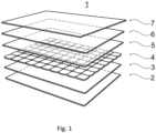
- FIG. 1 A known layer structure for a solar panel is shown.
- the solar panel 1 is built on a base plate 2, which can be a glass plate or a plastic film. This is followed by a plastic layer 3.
- the next layer contains solar cells 4, which are already electrically pre-connected.
- the solar cells are covered by another plastic layer 5, which, together with the plastic layer 3, provides insulation and sealing for the solar cells 4.
- a front glass or front film 6 is installed on the front, which is held by a frame 7.
- the prior art shown depicts monocrystalline solar cells 4 connected in series. Solar panels with thin-film technology can also be used for the inventive solution.
- Crystalline solar cells 4 are shown.
- the solar cells 4 are arranged in series and are electrically connected via contacts 8a and 8b.
- the five solar cells arranged one above the other are connected in series.
- the adjacent row of solar cells 4 is also connected in series.
- a single crystalline solar cell 4 has flattened corners and a square base. This results in an opening 11 in the assembly, which is located in the contact area of four solar cells.
- At least one LED 9 is inserted into each of these openings 11.
- the LEDs 9 are also connected in series and are located on a conduction strip 10. However, the LEDs can also be controlled and supplied separately via the conduction strip 10.
- the solar cells 4 must have a different shape and size.
- LEDs 9 are also possible when using thin-film technology for the application of the photosensitive layers.
- recesses must be provided during the application of the photosensitive materials so that LEDs 9 can be mounted in these recesses.
- the LEDs 9 are not installed in the layer of solar cells 4, but in one of the plastic layers 3, 5 or even in the front glass or the front film 6.
- the LEDs can also be installed in base plate 2.
- the electrical connection of the LEDs 9 is established via conductor tracks that can run parallel to the solar cell contacts.
- the actual electrical connections of the solar cells, located in the frame 7, can also be used to control the LEDs.
- the LEDs must be placed much more densely. Thin-film technology would be particularly suitable for this, as recesses are easy to create. Nine LEDs are then installed in the recesses, which can be individually controlled, thus providing a screen function.
- FIG 3 It shows how the installation can be carried out on a vehicle.
- a component of the vehicle's exterior structure 12 is covered by a flexible solar panel 1.
- LEDs 9 are installed in the solar panel 1, whereby it is irrelevant in which layer of the structure the LEDs 9 are installed.
- the solar panel 1 is covered on the vehicle by a transparent coating layer 13.
- the energy collected by the solar panel is fed into a battery 14 of the vehicle.
- Structural proximity is defined as the separate battery 14 having a shorter cable connection between solar panel 1 and battery 14 than the cable connection between solar panel 1 and the vehicle battery.
Landscapes
- Engineering & Computer Science (AREA)
- Power Engineering (AREA)
- Transportation (AREA)
- Mechanical Engineering (AREA)
- Chemical & Material Sciences (AREA)
- Combustion & Propulsion (AREA)
- Photovoltaic Devices (AREA)
Abstract
Fahrzeugaußenstruktur (12) mit Solarpaneel (1), wobei eine Basisplatte entweder von der Fahrzeugaußenstruktur oder von einer davon separaten Basisplatte (2) gebildet ist, die eine Schicht von monokristallinen Solarzellen (4) oder eine Dünnschicht-Photovoltaik (4) trägt, die zur Fahrzeugaußenfläche hin abgedeckt sind, wobei im Schichtaufbau des Solarpaneels (1) in einer der Schichten Beleuchtungselemente verbaut sind.
Description
- Die vorliegende Erfindung betrifft eine Fahrzeugaußenstruktur mit Solarzellen und Beleuchtungselementen.
- Bei vielen Elektrofahrzeugen werden Energiemanagement, Energiegewinnung oder Energieoptimierung immer wichtiger, gerade wenn man bedenkt wie viele Bauteile beleuchtet werden. Um einen Teil dieser Energie wiederzugewinnen, kommen Solarpaneele zum Einsatz.
-
EP 2 878 518 B1 zeigt eine Solarzelleneinheit mit einer Vielzahl von Solarzellen, die in planarer Form in Abständen voneinander angeordnet sind, und ein Versiegelungsharz, das die Vielzahl von Solarzellen abdichtet, sowie ein Dachpaneel, das transparent ist und zum Abdecken angeordnet ist, die Solarzelleneinheit von oben abdeckt und ein Verstärkungselement, das unter der Solarzelleneinheit angeordnet ist. - Vorteilhaft für Fahrzeuge sind Foliensolarpaneele, die einfache an Konturen angepasst werden können.
-
DE 10 2012 200 864 A1 betrifft ein Verfahren zur Herstellung eines Formteils mit mindestens einem Organischen-Photovoltaik-Modul. Um formstabile Photovoltaik-Module für beliebig geformte Flächen zur Verfügung zu stellen, umfasst das Verfahren die Verfahrensschritte: a) Fertigen mindestens eines Organischen-Photovoltaik-Moduls auf einem planaren Substrat; b) Formen des mit dem mindestens einen Organischem-Photovoltaik-Modul versehenen Substrats derart, dass mindestens ein gekrümmter Flächenabschnitt ausgebildet wird, welcher mindestens ein Organisches-Photovoltaik-Modul aufweist; und c) Fixieren der in Verfahrensschritt b) gegebenen Form. Darüber hinaus werden Formteile vorgestellt, bei denen mindestens ein gekrümmter Flächenabschnitt mindestens ein Organisches-Photovoltaik-Modul aufweist. -
EP 3 802 289 B1 zeigt eine Ausgestaltung, bei der eine Solarzellenfolie unmittelbar auf den Faserverbundkunststoff des Außenteils aufgebracht wird. Derartige photovoltaisch aktive Solarzellenfolien sind äußerst dünne Folien mit daran entsprechend ausgebildeten Solarzellen. Solche flexiblen Solarzellenfolien bestehen aus einer dünnen Trägerfolie, beispielsweise aus Polyimid, auf die eine photovoltaisch aktive Schicht beispielsweise aus Cadmiumtellurid aufgebracht wird, die gegebenenfalls rückseitig von einer weiteren extrem dünnen Trägerfolie beispielsweise aus Polyimid eingefasst ist. Der gesamte Folien- oder Schichtaufbau ist extrem dünn und daher äußerst flexibel. In einer besonders vorteilhaften Ausführungsform kann dabei vorgesehen sein, dass der Solarzellenabschnitt mit einer transparenten Lackschicht überzogen ist. Dabei kann der Lack der Lackschicht beispielsweise ein Epoxilack und/oder ein Polyimidlack sein. Eine derartige Ausgestaltung ermöglicht es zum einen, im Solarzellenabschnitt auf eine entsprechende Schutzschicht/Deckschicht zu verzichten bzw. diese einfacher auszugestalten, zum anderen aber, die Außenfläche letztlich komplett in einem Durchgang zu lackieren. - Unabhängig von der Art der Solarpaneel, ob starr oder folienflexibel, besteht ein Bedarf Informationen und/oder Beleuchtungen nach außen zubringen.
- Aus der
WO 2022 / 224 210 A1 ist ein Fahrzeug bekannt, dass einen Rahmen Aufbau aufweist, der teilweise mit Solarpaneele bestückt ist. Die Solarpaneele werden als einzelne Zellen verbaut, so dass zwischen ihnen freie Streifen oder Zonen entstehen. In diesen Streifen oder Zonen werden LED Lichtquellen verbaut. - Aus der
WO 2021 / 009 719 A1 ist ein Solarpanel bekannt, wie es für die Verwendung als Anzeige in der Stadt und auf dem Land eingesetzt wird. - Das beschriebene Solarpanel weist einen Aufbau auf, der die Solarzelle zwischen abdeckenden Folien zeigt, und wobei dieses photoaktive Paket auf einer Rückwand installiert ist. Abgedeckt wird das Ganze mit einer Glasscheibe. Auf der eigentlichen Solarzelle ist eine Displayschicht aufgebracht, die Lichtquellen aufweist.
- Die Aufgabe wird gelöst mit einer Fahrzeugaußenstruktur für den Außenbereiche eines Fahrzeugs, das Solarpaneele trägt und über LEDs in den Solarpaneelen beleuchtet ist.
- Die Aufgabe wird gelöst mit eine Fahrzeugaußenstruktur mit Solarpaneel, wobei einen Basisplatte entweder von der Fahrzeugaußenstruktur oder von einer davon separaten Basisplatte gebildet ist, die eine Schicht von monokristallinen Solarzellen oder eine Dünnschicht-Photovoltaik trägt, die zur Fahrzeugaußenfläche hin abgedeckt sind, wobei im Schichtaufbau des Solarpaneels in einer der Schichten Beleuchtungselemente verbaut sind.
- Dabei ist die Schicht der Solarzellen oder der Dünnschicht-Photovoltaik von Kunststofffolien umgeben ist.
- Die abdeckende Schicht ist eine Lackschicht.
- Es ist von Vorteil, dass die Beleuchtungselemente in Öffnungen zwischen monokristallinen Solarzellen oder in Aussparungen der Dünnschicht-Photovoltaik verbaut sind.
- Die Beleuchtungselemente sind in der Basisplatte oder den Kunststofffolien oder der abdeckenden Schicht verbaut.
- Dabei ist es vorteilhaft, dass die Beleuchtungselemente einzeln ansteuerbar sind und als Anzeigeelemente dienen.
- Die in den Solarpaneelen erzeugte Energie wird in einer Batterie des Fahrzeugs gespeichert, wobei eine separate Batterie für mindestens ein Solarpaneel nahe am einem der Solarpaneele verbaut ist.
-
-
Fig. 1 zeigt einen Aufbau eines Solarpanels, -
Fig. 2 zeigt ein Solarpanel mit LEDs, -
Fig.3 zeigt einen Aufbau auf einer Fahrzeugaußenhaut. - In der
Figur 1 ist ein bekannter Schichtaufbau für ein Solarpaneel dargelegt. Das Solarpaneel 1 wird auf einer Basisplatte 2 aufgebaut, wobei diese Basisplatte eine Glasplatte oder eine Kunststofffolie sein kann. Es folgt eine Kunststoffschicht 3. Als nächste Schicht werden Solarzellen 4, die bereits elektrisch vorverbunden sind, verbaut. Die Solarzellen werden von einer weiteren Kunststoffschicht 5 bedeckt, die zusammen mit der Kunststoffschicht 3 eine Isolierung und Abdichtung für die Solarzellen 4 darstellen. Frontseitig wird ein Frontglas oder eine Frontfolie 6 verbaut, die von einem Rahmen 7 gehalten ist. - Im gezeigten Stand der Technik sind monokristalline Solarzellen 4 dargestellt, die in Reihe verschaltet werden. Für die erfindungsgemäße Lösung lassen sich auch Solarpaneele mit Dünnschichttechnologie verwenden.
- In
Figur 2 sind kristalline Solarzellen 4 dargestellt. Die Solarzellen 4 sind in Reihe angeordnet und werden über Kontaktierung 8a und 8b elektrisch kontaktiert. Dabei sind in diesem Beispiel gezeigt, dass die fünf übereinander liegenden Solarzellen in Reihe geschaltet sind. Die daneben liegende Reihe von Solarzellen 4 ist ebenfalls in Reihe geschaltet. - Eine einzelne kristalline Solarzelle 4 weist in diesem Ausführungsbeispiel abgeflachte Ecken bei einer quadratischen Grundfläche auf. Dadurch ergibt sich im Zusammenbau jeweils eine Öffnung 11, die im Kontaktbereich von vier Solarzellen liegt.
- In diese Öffnung 11 wird jeweils mindestens eine LED 9 eingelegt. Die LEDs 9 sind ebenfalls in Reihe miteinander verbunden und sitzen auf einem Leitungsband 10. Die Ansteuerung und Versorgung der LEDs über das Leitungsband 10 kann aber auch getrennt voneinander erfolgen.
- Möchte man eine andere Anordnung der LEDs 9 haben, müssen die Solarzellen 4 eine andere Form und Größe aufweisen.
- Auch bei Verwendung einer Dünnschichttechnologie für das Auftragen der fotosensitiven Schichten ist der Einbau von LEDs 9 möglich. Dazu müssen bei dem Auftragen der fotosensitiven Materialien Aussparungen vorgesehen sein, damit in diesen Aussparungen LEDs 9 montiert werden können.
- In einer weiteren Ausführungsform sind die LEDs 9 nicht in der Schicht der Solarzellen 4 verbaut, sondern in einer der Kunststoffschichten 3, 5 oder sogar in dem Frontglas oder der Frontfolie 6.
- Bei der Verwendung von transparenten Solarzellen ist eine Installation der LEDs auch in der Basisplatte 2 möglich.
- Die elektrische Anbindung der LEDs 9 erfolgt über Leiterbahnen, die parallel zu den Kontaktierungen der Solarzellen verlaufen können. Die eigentlichen elektrischen Anschlüsse der Solarzellen, die sich im Rahmen 7 befinden, können auch zur Ansteuerung der LEDs benutzt werden.
- Möchte man über die reine Beleuchtungsfunktion der LEDs hinaus, Mitteilungen darstellen, müssen die LEDs sehr viel dichter gesetzt werden. Dafür würde sich vor allem die Dünnschichttechnologie eignen, da hier Aussparungen einfach herstellbar sind. In die Aussparungen werden dann LEDs 9 verbaut, die einzeln angesteuert werden können und so eine Bildschirmfunktion darstellen.
- In
Figur 3 ist gezeigt, wie der Aufbau an einem Fahrzeug erfolgen kann. Ein Bauteil der Fahrzeugaußenstruktur 12 ist von einem flexiblen Solarpaneel 1 bedeckt. Im Solarpaneel 1 sind LEDs 9 verbaut, wobei es nicht darauf ankommt, in welcher Schicht des Aufbaus die LEDs 9 eingebaut werden. Das Solarpaneel 1 wird am Fahrzeug von einer transparenten Lackschicht 13 abgedeckt. - Die gesammelte Energie des Solarpaneels wird in eine Batterie 14 des Fahrzeugs eingespeist.
- Dabei ist es nicht relevant, ob es sich um eine Fahrzeugbatterie oder eine separate Batterie handelt, die man in der Nähe des jeweiligen Solarpaneels verbaut. Dabei ist die bauliche Nähe so definiert, dass die separate Batterie 14 über einen kürzere Kabelverbindung zwischen Solarpaneel 1 und Batterie 14 verfügt als die Kabelverbindung zwischen Solarpaneel 1 und der Fahrzeugbatterie.
- Wenn die Batterie direkt am Solarpaneel verbaut ist, kann man ein Solarmodul gestalten, das als ein Modul am Fahrzeug verbaut wird.
Claims (6)
- Fahrzeugaußenstruktur (12) mit Solarpaneel (1), wobei eine Basisplatte entweder von der Fahrzeugaußenstruktur oder von einer davon separaten Basisplatte (2) gebildet ist, die eine Schicht von monokristallinen Solarzellen (4) oder eine Dünnschicht-Photovoltaik (4) trägt, die zur Fahrzeugaußenfläche hin mit einer abdeckenden Schicht abgedeckt sind, dadurch gekennzeichnet, dass im Schichtaufbau des Solarpaneels (1) in einer der Schichten Beleuchtungselemente verbaut sind, wobei die Schicht der monokristallinen Solarzellen (4) oder der Dünnschicht-Photovoltaik von Schichten aus Kunststofffolien (3, 5) umgeben ist und die abdeckende Schicht eine Lackschicht (13) ist.
- Fahrzeugaußenstruktur (12) nach Anspruch 1, dadurch gekennzeichnet, dass die Beleuchtungselemente in Öffnungen (11) zwischen monokristallinen Solarzellen (4) oder in Aussparungen der Dünnschicht-Photovoltaik verbaut sind.
- Fahrzeugaußenstruktur (12) nach Anspruch 1, dadurch gekennzeichnet, dass die Beleuchtungselemente in der Basisplatte (2) oder den Kunststofffolien (3, 5) oder der abdeckenden Lackschicht (13) verbaut sind.
- Fahrzeugaußenstruktur (12) nach Anspruch 1 , dadurch gekennzeichnet, dass die Beleuchtungselemente LEDs (9) sind.
- Fahrzeugaußenstruktur (12) nach Anspruch 1, dadurch gekennzeichnet, dass die Beleuchtungselemente einzeln ansteuerbar sind und als Anzeigeelemente dienen.
- Fahrzeugaußenstruktur (12) nach Anspruch 1, dadurch gekennzeichnet, dass die in den Solarpaneelen erzeugte Energie in einer Batterie des Fahrzeugs gespeichert wird, wobei eine separate Batterie (14) für mindestens ein Solarpaneel (1) nahe am einem der Solarpaneele verbaut ist.
Applications Claiming Priority (1)
| Application Number | Priority Date | Filing Date | Title |
|---|---|---|---|
| DE102023211216.7A DE102023211216A1 (de) | 2023-11-13 | 2023-11-13 | Fahrzeugaußenstruktur mit Solarzellen und Beleuchtungselementen |
Publications (1)
| Publication Number | Publication Date |
|---|---|
| EP4554089A1 true EP4554089A1 (de) | 2025-05-14 |
Family
ID=93335137
Family Applications (1)
| Application Number | Title | Priority Date | Filing Date |
|---|---|---|---|
| EP24209831.7A Withdrawn EP4554089A1 (de) | 2023-11-13 | 2024-10-30 | Fahrzeugaussenstruktur mit solarzellen und beleuchtungselementen |
Country Status (4)
| Country | Link |
|---|---|
| US (1) | US20250160005A1 (de) |
| EP (1) | EP4554089A1 (de) |
| CN (1) | CN119975165A (de) |
| DE (1) | DE102023211216A1 (de) |
Citations (6)
| Publication number | Priority date | Publication date | Assignee | Title |
|---|---|---|---|---|
| DE102012200864A1 (de) | 2012-01-23 | 2013-07-25 | Robert Bosch Gmbh | Organische Photovoltaik auf Freiformflächen |
| EP2878518B1 (de) | 2013-11-28 | 2017-06-14 | Kabushiki Kaisha Toyota Jidoshokki | Dachstruktur für ein Fahrzeug |
| IT201900012141A1 (it) * | 2019-07-17 | 2021-01-17 | Invent S R L | Pannello fotovoltaico perfezionato |
| CN114038347A (zh) * | 2021-12-14 | 2022-02-11 | 广州市祺虹电子科技有限公司 | 一种光伏发电显示屏 |
| EP3802289B1 (de) | 2018-06-08 | 2022-08-31 | Audi AG | Klappe für ein kraftfahrzeug und kraftfahrzeug |
| WO2022224210A1 (en) | 2021-04-23 | 2022-10-27 | Interactive Fully Electrical Vehicles S.R.L. | An electric vehicle with improved structure |
Family Cites Families (1)
| Publication number | Priority date | Publication date | Assignee | Title |
|---|---|---|---|---|
| US11584207B2 (en) * | 2021-01-29 | 2023-02-21 | Toyota Motor Engineering & Manufacturing North America, Inc. | Smart tonneau cover with solar panels and automatic weather sensing |
-
2023
- 2023-11-13 DE DE102023211216.7A patent/DE102023211216A1/de active Pending
-
2024
- 2024-10-23 US US18/923,958 patent/US20250160005A1/en active Pending
- 2024-10-30 EP EP24209831.7A patent/EP4554089A1/de not_active Withdrawn
- 2024-11-08 CN CN202411590656.3A patent/CN119975165A/zh active Pending
Patent Citations (7)
| Publication number | Priority date | Publication date | Assignee | Title |
|---|---|---|---|---|
| DE102012200864A1 (de) | 2012-01-23 | 2013-07-25 | Robert Bosch Gmbh | Organische Photovoltaik auf Freiformflächen |
| EP2878518B1 (de) | 2013-11-28 | 2017-06-14 | Kabushiki Kaisha Toyota Jidoshokki | Dachstruktur für ein Fahrzeug |
| EP3802289B1 (de) | 2018-06-08 | 2022-08-31 | Audi AG | Klappe für ein kraftfahrzeug und kraftfahrzeug |
| IT201900012141A1 (it) * | 2019-07-17 | 2021-01-17 | Invent S R L | Pannello fotovoltaico perfezionato |
| WO2021009719A1 (en) | 2019-07-17 | 2021-01-21 | Invent S.R.L. | An improved photovoltaic panel |
| WO2022224210A1 (en) | 2021-04-23 | 2022-10-27 | Interactive Fully Electrical Vehicles S.R.L. | An electric vehicle with improved structure |
| CN114038347A (zh) * | 2021-12-14 | 2022-02-11 | 广州市祺虹电子科技有限公司 | 一种光伏发电显示屏 |
Also Published As
| Publication number | Publication date |
|---|---|
| US20250160005A1 (en) | 2025-05-15 |
| CN119975165A (zh) | 2025-05-13 |
| DE102023211216A1 (de) | 2025-05-15 |
Similar Documents
| Publication | Publication Date | Title |
|---|---|---|
| EP1891681A1 (de) | Konzentrator-photovoltaik-einrichtung, daraus gebildetes pv- konzentratormodul sowie herstellverfahren hierfür | |
| EP3803984B1 (de) | Photovoltaisch aktives laminat | |
| AT12058U1 (de) | Verfahren zum kontaktieren eines photovoltaischen moduls mit einem anschlussgehäuse sowie system bestehend aus einem photovoltaischen modul und einem anschlussgehäuse | |
| WO2020065060A1 (de) | Erweiterte pv-anlage mit verbesserter effizienz | |
| EP2761670A1 (de) | Rahmenloses solarmodul mit montagelöchern | |
| DE10356690B4 (de) | Flexibles Solarmodul zur Dachintegration mit kristallinen Siliziumzellen | |
| DE2839038A1 (de) | Verfahren zur herstellung einer reihenschaltungsanordnung von sperrschicht-photozellen und nach diesem verfahren hergestellte photozellenanordnung oder -batterie | |
| EP4554089A1 (de) | Fahrzeugaussenstruktur mit solarzellen und beleuchtungselementen | |
| DE9315434U1 (de) | Wartehäuschen für Haltestellen von öffentlichen Verkehrsmitteln | |
| DE102012101245B4 (de) | Fahrzeugdach mit Solarzellenanordnung | |
| DE3626450A1 (de) | Als solarzelle wirkendes bauteil von bauwerken und gebaeuden | |
| WO1997015953A1 (de) | Solarzellen-beton-modul | |
| DE102004057663A1 (de) | Solarmodul | |
| DE102006021804A1 (de) | Solarzellenmodul sowie Verfahren zur Herstellung von Solarzellenmodulen | |
| WO2015028519A1 (de) | Teiltransparente dünnschichtsolarmodule | |
| DE102007052554A1 (de) | Solardach-Konstruktion für Kraftfahrzeuge | |
| WO2020127142A1 (de) | Schaltungsanordnung zur stromerzeugung mit serienverschalteten solarzellen mit bypass-dioden | |
| DE202018103447U1 (de) | Photovoltaikmodul | |
| DE102016125637A1 (de) | Photovoltaik-Modul und Verfahren zur Herstellung eines Photovoltaik-Moduls | |
| DE102013206629A1 (de) | Verfahren zur Herstellung eines Solarmoduls | |
| EP2590230A2 (de) | Photovoltaik-Freiflächenanlage | |
| DE102020133068B3 (de) | Textilaufbau mit flexiblen Solarzellen | |
| DE102006020019A1 (de) | Photovoltaik-Modul | |
| WO2013045147A1 (de) | Semitransparentes solarmodul und verglasungselement | |
| DE202024105083U1 (de) | Farbbeschichtung für ein Photovoltaikmodul |
Legal Events
| Date | Code | Title | Description |
|---|---|---|---|
| PUAI | Public reference made under article 153(3) epc to a published international application that has entered the european phase |
Free format text: ORIGINAL CODE: 0009012 |
|
| STAA | Information on the status of an ep patent application or granted ep patent |
Free format text: STATUS: THE APPLICATION HAS BEEN PUBLISHED |
|
| AK | Designated contracting states |
Kind code of ref document: A1 Designated state(s): AL AT BE BG CH CY CZ DE DK EE ES FI FR GB GR HR HU IE IS IT LI LT LU LV MC ME MK MT NL NO PL PT RO RS SE SI SK SM TR |
|
| STAA | Information on the status of an ep patent application or granted ep patent |
Free format text: STATUS: THE APPLICATION IS DEEMED TO BE WITHDRAWN |
|
| 18D | Application deemed to be withdrawn |
Effective date: 20251115 |