EP4553292A1 - Additive inflatable leak check bladder - Google Patents
Additive inflatable leak check bladder Download PDFInfo
- Publication number
- EP4553292A1 EP4553292A1 EP24211921.2A EP24211921A EP4553292A1 EP 4553292 A1 EP4553292 A1 EP 4553292A1 EP 24211921 A EP24211921 A EP 24211921A EP 4553292 A1 EP4553292 A1 EP 4553292A1
- Authority
- EP
- European Patent Office
- Prior art keywords
- bladder
- bladder body
- assembly
- component assembly
- port
- Prior art date
- Legal status (The legal status is an assumption and is not a legal conclusion. Google has not performed a legal analysis and makes no representation as to the accuracy of the status listed.)
- Granted
Links
Images

Classifications
-
- G—PHYSICS
- G01—MEASURING; TESTING
- G01M—TESTING STATIC OR DYNAMIC BALANCE OF MACHINES OR STRUCTURES; TESTING OF STRUCTURES OR APPARATUS, NOT OTHERWISE PROVIDED FOR
- G01M3/00—Investigating fluid-tightness of structures
- G01M3/02—Investigating fluid-tightness of structures by using fluid or vacuum
- G01M3/025—Details with respect to the testing of engines or engine parts
-
- F—MECHANICAL ENGINEERING; LIGHTING; HEATING; WEAPONS; BLASTING
- F01—MACHINES OR ENGINES IN GENERAL; ENGINE PLANTS IN GENERAL; STEAM ENGINES
- F01D—NON-POSITIVE DISPLACEMENT MACHINES OR ENGINES, e.g. STEAM TURBINES
- F01D21/00—Shutting-down of machines or engines, e.g. in emergency; Regulating, controlling, or safety means not otherwise provided for
- F01D21/003—Arrangements for testing or measuring
-
- F—MECHANICAL ENGINEERING; LIGHTING; HEATING; WEAPONS; BLASTING
- F16—ENGINEERING ELEMENTS AND UNITS; GENERAL MEASURES FOR PRODUCING AND MAINTAINING EFFECTIVE FUNCTIONING OF MACHINES OR INSTALLATIONS; THERMAL INSULATION IN GENERAL
- F16J—PISTONS; CYLINDERS; SEALINGS
- F16J15/00—Sealings
- F16J15/46—Sealings with packing ring expanded or pressed into place by fluid pressure, e.g. inflatable packings
-
- F—MECHANICAL ENGINEERING; LIGHTING; HEATING; WEAPONS; BLASTING
- F16—ENGINEERING ELEMENTS AND UNITS; GENERAL MEASURES FOR PRODUCING AND MAINTAINING EFFECTIVE FUNCTIONING OF MACHINES OR INSTALLATIONS; THERMAL INSULATION IN GENERAL
- F16L—PIPES; JOINTS OR FITTINGS FOR PIPES; SUPPORTS FOR PIPES, CABLES OR PROTECTIVE TUBING; MEANS FOR THERMAL INSULATION IN GENERAL
- F16L55/00—Devices or appurtenances for use in, or in connection with, pipes or pipe systems
- F16L55/10—Means for stopping flow in pipes or hoses
- F16L55/12—Means for stopping flow in pipes or hoses by introducing into the pipe a member expandable in situ
- F16L55/128—Means for stopping flow in pipes or hoses by introducing into the pipe a member expandable in situ introduced axially into the pipe or hose
- F16L55/1283—Plugging pig
-
- F—MECHANICAL ENGINEERING; LIGHTING; HEATING; WEAPONS; BLASTING
- F16—ENGINEERING ELEMENTS AND UNITS; GENERAL MEASURES FOR PRODUCING AND MAINTAINING EFFECTIVE FUNCTIONING OF MACHINES OR INSTALLATIONS; THERMAL INSULATION IN GENERAL
- F16L—PIPES; JOINTS OR FITTINGS FOR PIPES; SUPPORTS FOR PIPES, CABLES OR PROTECTIVE TUBING; MEANS FOR THERMAL INSULATION IN GENERAL
- F16L55/00—Devices or appurtenances for use in, or in connection with, pipes or pipe systems
- F16L55/10—Means for stopping flow in pipes or hoses
- F16L55/12—Means for stopping flow in pipes or hoses by introducing into the pipe a member expandable in situ
- F16L55/128—Means for stopping flow in pipes or hoses by introducing into the pipe a member expandable in situ introduced axially into the pipe or hose
- F16L55/132—Means for stopping flow in pipes or hoses by introducing into the pipe a member expandable in situ introduced axially into the pipe or hose the closure device being a plug fixed by radially deforming the packing
- F16L55/134—Means for stopping flow in pipes or hoses by introducing into the pipe a member expandable in situ introduced axially into the pipe or hose the closure device being a plug fixed by radially deforming the packing by means of an inflatable packing
-
- G—PHYSICS
- G01—MEASURING; TESTING
- G01M—TESTING STATIC OR DYNAMIC BALANCE OF MACHINES OR STRUCTURES; TESTING OF STRUCTURES OR APPARATUS, NOT OTHERWISE PROVIDED FOR
- G01M3/00—Investigating fluid-tightness of structures
- G01M3/02—Investigating fluid-tightness of structures by using fluid or vacuum
- G01M3/022—Test plugs for closing off the end of a pipe
-
- F—MECHANICAL ENGINEERING; LIGHTING; HEATING; WEAPONS; BLASTING
- F01—MACHINES OR ENGINES IN GENERAL; ENGINE PLANTS IN GENERAL; STEAM ENGINES
- F01D—NON-POSITIVE DISPLACEMENT MACHINES OR ENGINES, e.g. STEAM TURBINES
- F01D25/00—Component parts, details, or accessories, not provided for in, or of interest apart from, other groups
- F01D25/28—Supporting or mounting arrangements, e.g. for turbine casing
- F01D25/285—Temporary support structures, e.g. for testing, assembling, installing, repairing; Assembly methods using such structures
-
- F—MECHANICAL ENGINEERING; LIGHTING; HEATING; WEAPONS; BLASTING
- F01—MACHINES OR ENGINES IN GENERAL; ENGINE PLANTS IN GENERAL; STEAM ENGINES
- F01D—NON-POSITIVE DISPLACEMENT MACHINES OR ENGINES, e.g. STEAM TURBINES
- F01D5/00—Blades; Blade-carrying members; Heating, heat-insulating, cooling or antivibration means on the blades or the members
- F01D5/005—Repairing methods or devices
-
- F—MECHANICAL ENGINEERING; LIGHTING; HEATING; WEAPONS; BLASTING
- F05—INDEXING SCHEMES RELATING TO ENGINES OR PUMPS IN VARIOUS SUBCLASSES OF CLASSES F01-F04
- F05D—INDEXING SCHEME FOR ASPECTS RELATING TO NON-POSITIVE-DISPLACEMENT MACHINES OR ENGINES, GAS-TURBINES OR JET-PROPULSION PLANTS
- F05D2300/00—Materials; Properties thereof
- F05D2300/40—Organic materials
- F05D2300/43—Synthetic polymers, e.g. plastics; Rubber
- F05D2300/431—Rubber
-
- F—MECHANICAL ENGINEERING; LIGHTING; HEATING; WEAPONS; BLASTING
- F05—INDEXING SCHEMES RELATING TO ENGINES OR PUMPS IN VARIOUS SUBCLASSES OF CLASSES F01-F04
- F05D—INDEXING SCHEME FOR ASPECTS RELATING TO NON-POSITIVE-DISPLACEMENT MACHINES OR ENGINES, GAS-TURBINES OR JET-PROPULSION PLANTS
- F05D2300/00—Materials; Properties thereof
- F05D2300/40—Organic materials
- F05D2300/43—Synthetic polymers, e.g. plastics; Rubber
- F05D2300/437—Silicon polymers
-
- F—MECHANICAL ENGINEERING; LIGHTING; HEATING; WEAPONS; BLASTING
- F05—INDEXING SCHEMES RELATING TO ENGINES OR PUMPS IN VARIOUS SUBCLASSES OF CLASSES F01-F04
- F05D—INDEXING SCHEME FOR ASPECTS RELATING TO NON-POSITIVE-DISPLACEMENT MACHINES OR ENGINES, GAS-TURBINES OR JET-PROPULSION PLANTS
- F05D2300/00—Materials; Properties thereof
- F05D2300/50—Intrinsic material properties or characteristics
- F05D2300/501—Elasticity
-
- G—PHYSICS
- G01—MEASURING; TESTING
- G01M—TESTING STATIC OR DYNAMIC BALANCE OF MACHINES OR STRUCTURES; TESTING OF STRUCTURES OR APPARATUS, NOT OTHERWISE PROVIDED FOR
- G01M3/00—Investigating fluid-tightness of structures
- G01M3/005—Investigating fluid-tightness of structures using pigs or moles
-
- G—PHYSICS
- G01—MEASURING; TESTING
- G01M—TESTING STATIC OR DYNAMIC BALANCE OF MACHINES OR STRUCTURES; TESTING OF STRUCTURES OR APPARATUS, NOT OTHERWISE PROVIDED FOR
- G01M3/00—Investigating fluid-tightness of structures
- G01M3/02—Investigating fluid-tightness of structures by using fluid or vacuum
- G01M3/04—Investigating fluid-tightness of structures by using fluid or vacuum by detecting the presence of fluid at the leakage point
-
- G—PHYSICS
- G01—MEASURING; TESTING
- G01M—TESTING STATIC OR DYNAMIC BALANCE OF MACHINES OR STRUCTURES; TESTING OF STRUCTURES OR APPARATUS, NOT OTHERWISE PROVIDED FOR
- G01M3/00—Investigating fluid-tightness of structures
- G01M3/02—Investigating fluid-tightness of structures by using fluid or vacuum
- G01M3/26—Investigating fluid-tightness of structures by using fluid or vacuum by measuring rate of loss or gain of fluid, e.g. by pressure-responsive devices, by flow detectors
-
- G—PHYSICS
- G01—MEASURING; TESTING
- G01M—TESTING STATIC OR DYNAMIC BALANCE OF MACHINES OR STRUCTURES; TESTING OF STRUCTURES OR APPARATUS, NOT OTHERWISE PROVIDED FOR
- G01M3/00—Investigating fluid-tightness of structures
- G01M3/02—Investigating fluid-tightness of structures by using fluid or vacuum
- G01M3/36—Investigating fluid-tightness of structures by using fluid or vacuum by detecting change in dimensions of the structure being tested
Definitions
- the present disclosure relates generally to leak checks in constrained spaces and, more particularly, to an approach for sealing a component assembly in a constrained space in order to perform a leak check.
- Component assemblies including but not limited to brazed component assemblies, are commonly used in a variety of industrial applications including, but not limited to, gas turbine engine applications.
- joints in component assemblies must be leak-free to permit select fluids, including liquids and gases, to flow through the component assemblies without leaking.
- component assemblies are typically leak checked after fabrication.
- a typical leak check includes sealing all openings in the component assembly and filling the component assembly with a pressurized fluid, e.g., water, air, nitrogen, or another fluid, and determining whether the sealed and pressurized component assembly will hold pressure. Alternately, the leak check can be conducted with a vacuum to determine whether the sealed and evacuated component assembly will hold a vacuum.
- a pressurized fluid e.g., water, air, nitrogen, or another fluid
- the inflatable bladder includes a bladder body, a sealing surface, and an intake port.
- the bladder body has an outer skin surrounding a hollow inner volume.
- the bladder body is formed from an elastomeric material such that the bladder body is configured to expand to a rigid or semi-rigid structure when in an inflated state and to collapse to a flaccid structure when in a deflated state.
- the sealing surface is configured to form a leak-tight seal against a port in a component assembly.
- the intake port is configured to direct a pressurizing fluid into and out of the hollow inner volume of the bladder body to inflate the bladder to the inflated state and deflate the bladder body to the deflated state.
- the bladder body is configured to be positioned within a constrained space in an industrial assembly when the bladder body is in the deflated state and is configured to conform to a geometry of the constrained space when the bladder body is in the inflated state, such that when the bladder body is in the inflated state, the sealing surface engages with the port in the component assembly to form a leak-tight seal.
- At least a portion of the outer skin comprises an isogrid structure.
- the elastomeric material is selected from the group consisting of natural rubber, artificial rubber, polyurethane, and silicone rubber.
- the elastomeric material is a light-curable resin useful in a stereo lithography process.
- the component assembly is configured to operate as a fluid conduit in the industrial assembly.
- the constrained space includes one or more interior structures that impede access to the port in the component assembly.
- the industrial assembly is a structure of a gas turbine engine.
- Another aspect of the present invention is a method of leak checking a component assembly positioned in an industrial assembly.
- An inflatable bladder is inserted into a constrained space of the industrial assembly while the inflatable bladder is in a deflated state.
- the inflatable bladder is inflated to a rigid or semi-rigid inflated state by directing a pressurizing fluid through an intake port in the inflatable bladder into a hollow inner volume of a bladder body, causing the inflatable bladder to conform to a geometry of the constrained space and causing a sealing surface of the inflatable bladder to engage with a port in the component assembly to form a leak-tight seal.
- a leak check test is conducted on the component assembly.
- the inflatable bladder is deflated by evacuating the pressurizing fluid from the intake port in the inflatable bladder, causing the inflatable bladder to enter a flaccid deflated state and the inflatable bladder is removed from the constrained space of the industrial assembly.
- the bladder body includes an outer skin that defines the hollow inner volume of the bladder body.
- At least a portion of the outer skin comprises an isogrid structure.
- the elastomeric material is selected from the group consisting of natural rubber, artificial rubber, polyurethane, and silicone rubber.
- the elastomeric material is a light-curable resin useful in a stereo lithography process.
- the component assembly is configured to operate as a fluid conduit in the industrial assembly.
- the constrained space includes one or more interior structures that impede access to the port in the component assembly.
- the industrial assembly is a structure of a gas turbine engine.
- Component assemblies including but not limited to brazed component assemblies, are typically leak checked after fabrication to ensure they can effectively perform their function as conduits for various fluids.
- Many different leak check procedures are known in the art. Typically, such procedures include sealing all openings in the component assembly and filling the component assembly with a pressurized fluid, e.g., water, air, nitrogen, or another fluid, and determining whether the sealed and pressurized component assembly will hold pressure. Alternately, the leak check can be conducted with a vacuum to determine whether the sealed and evacuated component assembly will hold a vacuum.
- Component assemblies are typically sealed with conventional sealing means including plugs, stoppers, bungs, and other sealing means know in the art. However, in some applications, component assemblies may be positioned in a physically and/or geometrically constrained space in a larger assembly that makes it difficult or impossible to seal openings in the component assemblies using conventional means to conduct the leak check.
- Figs. 1A and 1B show an exemplary environment in which a component assembly 10 is positioned in a constrained space 12 that forms part of a larger industrial assembly 14.
- the industrial assembly 14 can be any of a number of industrial products that incorporate a component assembly 10.
- the industrial assembly 14 can be part of a gas turbine engine as shown in Figs. 1A and 1B or some other industrial assembly.
- the constrained space 12 can include one or more interior structures 16, 18 that can obstruct access to the component assembly 10, particularly to a port 20 in the component assembly 10.
- FIGs. 1A and 1B are examples of interior structures 16, 18 that can obstruct access to the component assembly 10 and are not meant to be limiting.
- a person of ordinary skill will understand that many other types and shapes of interior structures positioned in a constrained space of an industrial structure could obstruct access to a component assembly.
- the positioning of the interior structures 16, 18 in the constrained space 12 makes it difficult or impossible to seal the port 20 in the component assembly 10 so than the component assembly 10 can be leak checked.
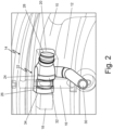
- Fig. 2 shows a conformal sealing fixture 22 configured to seal a port 20 in the component assembly 10.
- the conformal sealing fixture 22 includes an inflatable bladder 24 with a bladder body 26, a sealing surface 28, and an intake port 30.
- the bladder body 26 has an outer skin 32 surrounding a hollow inner volume (not shown directly).
- the bladder body 26 is formed from an elastomeric material such that the bladder body is configured to expand to a rigid or semi-rigid structure when in an inflated state and to collapse to a flaccid structure when in a deflated state.
- the sealing surface 28 is configured to form a leak-tight seal against the port 20 in the component assembly 10.
- the intake port 30 is configured to direct a pressurizing fluid into and out of the hollow inner volume of the bladder body to inflate the bladder to the inflated state and deflate the bladder body to the deflated state.
- the bladder body 26 is configured to be positioned within the constrained space 12 in the industrial assembly 14 when the bladder body 26 is in the deflated state. As shown in Fig. 2 , the bladder body 26 is configured to conform to the geometry of the constrained space 12 when the bladder body is in the inflated state. In this example, the bladder body 26 is structure to fit between interior structure 18 and the component assembly 10 and to surround partially interior structure 16. Optionally, the bladder body 26 can include a support face 34 that is configured to fit against an interior structure, such as interior structure 18, to stabilize and support the conformal sealing fixture 22 in the constrained space 12.
- the bladder body 26 can be sized to provide a tight fit in the constrained space 12 when the bladder body 26 is in its inflated state also to stabilize and support the conformal sealing fixture 22 in the constrained space 12.
- the outer skin 32 can be constructed with selected friction characteristics as an additional measure to stabilize and support the conformal sealing fixture 22 in the constrained space 12.
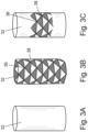
- an isogrid structure 36 is a partially hollowed-out thin skin reinforced with a lattice structure having triangular integral stiffening ribs 38, sometimes called stringers.
- the isogrid structure 36 permits the bladder body 26 to contract and inflate like an accordion. When inflated, the isogrid's triangular pattern retains rigidity with less material than non-isogrid structures, thereby saving material and weight.
- the conformal sealing fixture 22 is formed of an elastomeric material to allow it to inflate to an inflated state and deflate to a deflated state.
- the elastomeric material can be any material capable of inflating to form a leak-tight seal when the sealing surface 28 engages with the port 20 in the component assembly 10.
- the elastomeric material can be natural rubber, artificial rubber, polyurethane, silicone rubber, or any other suitable elastomer.
- the conformal sealing fixture is made with an additive manufacturing method as discussed below, the elastomeric material can be a light-curable resin useful in a stereo lithography process.
- the elastomeric material can be selected to impart desirable friction characteristics to the outer skin 32 to stabilize and support the conformal sealing fixture 22 in the constrained space 12.
- the conformal sealing fixture 22 can be made with any method capable of forming a bladder body 26 having an outer skin 32 surrounding a hollow inner volume, which could be described as a shaped, balloon-like structure.
- additive manufacturing techniques such as vat photopolymerization (e.g., stereolithography or other techniques known as vat photopolymerization) or material jetting can be used to create the bladder body 26 with the desired geometry and mechanical properties.
- the outer skin 32 can be formed from an elastomeric material as discussed above with a soluble resin used to form an interior space between the outer skin 32.
- the soluble resin can be any material can be dissolved or washed out of the bladder body 26 after it is formed to create the hollow inner volume surrounded by the outer skin 32.
- some or all of the outer skin 32 can be formed with an isogrid structure 36 as deemed appropriate for a particular application. of the bladder.
- the conformal sealing fixture 22 described above will reduce time to provide a seal to leak check a component assembly 10 that is positioned in constrained space 12 and eliminate multi-part complex fixtures and seals.
- the conformal sealing fixture 22 also has built in mistake-proofing due to the bladder body 26 being conformal to geometry of the constrained space 12 in which it is intended to be used.
- a conformal sealing fixture comprising an inflatable bladder having a bladder body having an outer skin surrounding a hollow inner volume, a sealing surface, and an intake port configured to direct a pressurizing fluid into and out of the hollow inner volume of the bladder body to inflate the bladder to the inflated state and deflate the bladder body to the deflated state.
- the bladder body is formed from an elastomeric material such that the bladder body is configured to expand to a rigid or semi-rigid structure when in an inflated state and to collapse to a flaccid structure when in a deflated state.
- the sealing surface is configured to form a leak-tight seal against a port in a component assembly.
- the bladder body is configured to be positioned within a constrained space in an industrial assembly when the bladder body is in the deflated state and is configured to conform to a geometry of the constrained space when the bladder body is in the inflated state, such that when the bladder body is in the inflated state, the sealing surface engages with the port in the component assembly to form a leak-tight seal.
- the conformal sealing fixture of the preceding paragraph can optionally include, additionally and/or alternatively, any one or more of the following features, configurations and/or additional elements:
- the elastomeric material is selected from the group consisting of natural rubber, artificial rubber, polyurethane, and silicone rubber.
- the conformal sealing fixture of any of the preceding paragraphs wherein the constrained space includes one or more interior structures that impede access to the port in the component assembly.
- a method of leak checking a component assembly positioned in an industrial assembly comprising the steps of inserting an inflatable bladder into a constrained space of the industrial assembly, wherein the inflatable bladder is in a deflated state; inflating the inflatable bladder to a rigid or semi-rigid inflated state by directing a pressurizing fluid through an intake port in the inflatable bladder into a hollow inner volume of a bladder body, thereby causing the inflatable bladder to conform to a geometry of the constrained space and causing a sealing surface of the inflatable bladder to engage with a port in the component assembly to form a leak-tight seal; conducing a leak check test on the component assembly; deflating the inflatable bladder by evacuating the pressurizing fluid from the intake port in the inflatable bladder, thereby causing the inflatable bladder to enter a flaccid deflated state; and removing the inflatable bladder from the constrained space of the industrial assembly.
- the method of the preceding paragraph can optionally include, additionally and/or alternatively, any one or more of the following features, configurations and/or additional elements:
- the method of the preceding claim wherein the bladder body includes an outer skin that defines the hollow inner volume of the bladder body.
- the bladder body is formed from an elastomeric material such that the bladder body is configured to expand to a semi-rigid structure when in an inflated state and to collapse to a flaccid structure when in a deflated state.
- the elastomeric material is selected from the group consisting of natural rubber, artificial rubber, polyurethane, and silicone rubber.
- the elastomeric material is a light-curable resin useful in a stereo lithography process.
- the constrained space includes one or more interior structures that impede access to the port in the component assembly.
Landscapes
- Engineering & Computer Science (AREA)
- General Engineering & Computer Science (AREA)
- Mechanical Engineering (AREA)
- Physics & Mathematics (AREA)
- General Physics & Mathematics (AREA)
- Architecture (AREA)
- Fluid Mechanics (AREA)
- Gasket Seals (AREA)
- Actuator (AREA)
Abstract
Description
- The present disclosure relates generally to leak checks in constrained spaces and, more particularly, to an approach for sealing a component assembly in a constrained space in order to perform a leak check.
- Component assemblies, including but not limited to brazed component assemblies, are commonly used in a variety of industrial applications including, but not limited to, gas turbine engine applications. To be useful, joints in component assemblies must be leak-free to permit select fluids, including liquids and gases, to flow through the component assemblies without leaking. To ensure leak-free joints, including but not limited to brazed joints, in component assemblies, component assemblies are typically leak checked after fabrication. A typical leak check includes sealing all openings in the component assembly and filling the component assembly with a pressurized fluid, e.g., water, air, nitrogen, or another fluid, and determining whether the sealed and pressurized component assembly will hold pressure. Alternately, the leak check can be conducted with a vacuum to determine whether the sealed and evacuated component assembly will hold a vacuum. Component assemblies are typically sealed with conventional sealing means including stoppers, bungs, and other sealing means know in the art. In some applications, though, component assemblies may be positioned in a physically and/or geometrically constrained space in a larger assembly that makes it difficult or impossible to seal openings in the component assemblies using conventional means.
- One aspect of the present invention is a conformal sealing fixture including an inflatable bladder. The inflatable bladder includes a bladder body, a sealing surface, and an intake port. The bladder body has an outer skin surrounding a hollow inner volume. The bladder body is formed from an elastomeric material such that the bladder body is configured to expand to a rigid or semi-rigid structure when in an inflated state and to collapse to a flaccid structure when in a deflated state. The sealing surface is configured to form a leak-tight seal against a port in a component assembly. The intake port is configured to direct a pressurizing fluid into and out of the hollow inner volume of the bladder body to inflate the bladder to the inflated state and deflate the bladder body to the deflated state. The bladder body is configured to be positioned within a constrained space in an industrial assembly when the bladder body is in the deflated state and is configured to conform to a geometry of the constrained space when the bladder body is in the inflated state, such that when the bladder body is in the inflated state, the sealing surface engages with the port in the component assembly to form a leak-tight seal.
- In an embodiment of the above, at least a portion of the outer skin comprises an isogrid structure.
- In an embodiment according to any of the previous embodiments, the elastomeric material is selected from the group consisting of natural rubber, artificial rubber, polyurethane, and silicone rubber.
- In an embodiment according to any of the previous embodiments, the elastomeric material is a light-curable resin useful in a stereo lithography process.
- In an embodiment according to any of the previous embodiments, the component assembly is configured to operate as a fluid conduit in the industrial assembly.
- In an embodiment according to any of the previous embodiments, the constrained space includes one or more interior structures that impede access to the port in the component assembly.
- In an embodiment according to any of the previous embodiments, the industrial assembly is a structure of a gas turbine engine.
- Another aspect of the present invention is a method of leak checking a component assembly positioned in an industrial assembly. An inflatable bladder is inserted into a constrained space of the industrial assembly while the inflatable bladder is in a deflated state. The inflatable bladder is inflated to a rigid or semi-rigid inflated state by directing a pressurizing fluid through an intake port in the inflatable bladder into a hollow inner volume of a bladder body, causing the inflatable bladder to conform to a geometry of the constrained space and causing a sealing surface of the inflatable bladder to engage with a port in the component assembly to form a leak-tight seal. A leak check test is conducted on the component assembly. The inflatable bladder is deflated by evacuating the pressurizing fluid from the intake port in the inflatable bladder, causing the inflatable bladder to enter a flaccid deflated state and the inflatable bladder is removed from the constrained space of the industrial assembly.
- In an embodiment of the above, the bladder body includes an outer skin that defines the hollow inner volume of the bladder body.
- In an embodiment according to any of the previous embodiments, at least a portion of the outer skin comprises an isogrid structure.
- In an embodiment according to any of the previous embodiments, the bladder body is formed from an elastomeric material such that the bladder body is configured to expand to a semi-rigid structure when in an inflated state and to collapse to a flaccid structure when in a deflated state.
- In an embodiment according to any of the previous embodiments, the elastomeric material is selected from the group consisting of natural rubber, artificial rubber, polyurethane, and silicone rubber.
- In an embodiment according to any of the previous embodiments, the elastomeric material is a light-curable resin useful in a stereo lithography process.
- In an embodiment according to any of the previous embodiments, the component assembly is configured to operate as a fluid conduit in the industrial assembly.
- In an embodiment according to any of the previous embodiments, the constrained space includes one or more interior structures that impede access to the port in the component assembly.
- In an embodiment according to any of the previous embodiments, the industrial assembly is a structure of a gas turbine engine.
-
-
Fig. 1A is a view of an interior portion of a gas turbine engine assembly. -
Fig. 1B is another view of the interior portion of the gas turbine engine assembly ofFig. 1A . -
Fig. 2 is an isometric view an inflatable leak check bladder of this disclosure positioned in the interior portion of the gas turbine engine assembly ofFigs. 1A and 1B .. -
Figs. 3A to 3C are alternate views of the skin of the leak check bladder ofFig. 2 showing a smooth skin (Fig. 3A ), a skin with an isogrid structure (Fig. 3B ), and a skin with a partial isogrid structure (Fig. 3C ). - Component assemblies, including but not limited to brazed component assemblies, are typically leak checked after fabrication to ensure they can effectively perform their function as conduits for various fluids. Many different leak check procedures are known in the art. Typically, such procedures include sealing all openings in the component assembly and filling the component assembly with a pressurized fluid, e.g., water, air, nitrogen, or another fluid, and determining whether the sealed and pressurized component assembly will hold pressure. Alternately, the leak check can be conducted with a vacuum to determine whether the sealed and evacuated component assembly will hold a vacuum. Component assemblies are typically sealed with conventional sealing means including plugs, stoppers, bungs, and other sealing means know in the art. However, in some applications, component assemblies may be positioned in a physically and/or geometrically constrained space in a larger assembly that makes it difficult or impossible to seal openings in the component assemblies using conventional means to conduct the leak check.
-
Figs. 1A and 1B show an exemplary environment in which acomponent assembly 10 is positioned in aconstrained space 12 that forms part of a largerindustrial assembly 14. Theindustrial assembly 14 can be any of a number of industrial products that incorporate acomponent assembly 10. For example, theindustrial assembly 14 can be part of a gas turbine engine as shown inFigs. 1A and 1B or some other industrial assembly. As depicted inFigs. 1A and 1B , theconstrained space 12 can include one or moreinterior structures component assembly 10, particularly to aport 20 in thecomponent assembly 10. Theinterior structures Figs. 1A and 1B are examples ofinterior structures component assembly 10 and are not meant to be limiting. A person of ordinary skill will understand that many other types and shapes of interior structures positioned in a constrained space of an industrial structure could obstruct access to a component assembly. As seen inFigs. 1A and 1B , the positioning of theinterior structures space 12 makes it difficult or impossible to seal theport 20 in thecomponent assembly 10 so than thecomponent assembly 10 can be leak checked. -
Fig. 2 shows aconformal sealing fixture 22 configured to seal aport 20 in thecomponent assembly 10. Theconformal sealing fixture 22 includes aninflatable bladder 24 with abladder body 26, a sealingsurface 28, and anintake port 30. Thebladder body 26 has anouter skin 32 surrounding a hollow inner volume (not shown directly). Thebladder body 26 is formed from an elastomeric material such that the bladder body is configured to expand to a rigid or semi-rigid structure when in an inflated state and to collapse to a flaccid structure when in a deflated state. The sealingsurface 28 is configured to form a leak-tight seal against theport 20 in thecomponent assembly 10. Theintake port 30 is configured to direct a pressurizing fluid into and out of the hollow inner volume of the bladder body to inflate the bladder to the inflated state and deflate the bladder body to the deflated state. - The
bladder body 26 is configured to be positioned within the constrainedspace 12 in theindustrial assembly 14 when thebladder body 26 is in the deflated state. As shown inFig. 2 , thebladder body 26 is configured to conform to the geometry of the constrainedspace 12 when the bladder body is in the inflated state. In this example, thebladder body 26 is structure to fit betweeninterior structure 18 and thecomponent assembly 10 and to surround partiallyinterior structure 16. Optionally, thebladder body 26 can include asupport face 34 that is configured to fit against an interior structure, such asinterior structure 18, to stabilize and support theconformal sealing fixture 22 in the constrainedspace 12. Additionally, thebladder body 26 can be sized to provide a tight fit in the constrainedspace 12 when thebladder body 26 is in its inflated state also to stabilize and support theconformal sealing fixture 22 in the constrainedspace 12. As discussed further below, theouter skin 32 can be constructed with selected friction characteristics as an additional measure to stabilize and support theconformal sealing fixture 22 in the constrainedspace 12. When thebladder body 26 is in its inflated state, the sealingsurface 28 engages with theport 20 in thecomponent assembly 10 to form a leak-tight seal that will support a leak check test on thecomponent assembly 10. - While the
outer skin 32 ofbladder body 26 is shown inFig. 2 (see alsoFig. 3A ) with a smooth surface, it is also possible to form theouter skin 32 with anisogrid structure 36, shown inFigs. 3B and 3C , on all (Fig. 3B ) or some (Fig. 3C ) of theouter skin 32. As known, anisogrid structure 36 is a partially hollowed-out thin skin reinforced with a lattice structure having triangular integral stiffening ribs 38, sometimes called stringers. Theisogrid structure 36 permits thebladder body 26 to contract and inflate like an accordion. When inflated, the isogrid's triangular pattern retains rigidity with less material than non-isogrid structures, thereby saving material and weight. - The
conformal sealing fixture 22 is formed of an elastomeric material to allow it to inflate to an inflated state and deflate to a deflated state. The elastomeric material can be any material capable of inflating to form a leak-tight seal when the sealingsurface 28 engages with theport 20 in thecomponent assembly 10. For example, the elastomeric material can be natural rubber, artificial rubber, polyurethane, silicone rubber, or any other suitable elastomer. If the conformal sealing fixture is made with an additive manufacturing method as discussed below, the elastomeric material can be a light-curable resin useful in a stereo lithography process. The elastomeric material can be selected to impart desirable friction characteristics to theouter skin 32 to stabilize and support theconformal sealing fixture 22 in the constrainedspace 12. - The
conformal sealing fixture 22 can be made with any method capable of forming abladder body 26 having anouter skin 32 surrounding a hollow inner volume, which could be described as a shaped, balloon-like structure. For example, additive manufacturing techniques such as vat photopolymerization (e.g., stereolithography or other techniques known as vat photopolymerization) or material jetting can be used to create thebladder body 26 with the desired geometry and mechanical properties. In one option, theouter skin 32 can be formed from an elastomeric material as discussed above with a soluble resin used to form an interior space between theouter skin 32. The soluble resin can be any material can be dissolved or washed out of thebladder body 26 after it is formed to create the hollow inner volume surrounded by theouter skin 32. As discussed some or all of theouter skin 32 can be formed with anisogrid structure 36 as deemed appropriate for a particular application. of the bladder. - The
conformal sealing fixture 22 described above will reduce time to provide a seal to leak check acomponent assembly 10 that is positioned in constrainedspace 12 and eliminate multi-part complex fixtures and seals. Theconformal sealing fixture 22 also has built in mistake-proofing due to thebladder body 26 being conformal to geometry of the constrainedspace 12 in which it is intended to be used. - The following are non-exclusive descriptions of possible embodiments of the present invention.
- A conformal sealing fixture comprising an inflatable bladder having a bladder body having an outer skin surrounding a hollow inner volume, a sealing surface, and an intake port configured to direct a pressurizing fluid into and out of the hollow inner volume of the bladder body to inflate the bladder to the inflated state and deflate the bladder body to the deflated state. The bladder body is formed from an elastomeric material such that the bladder body is configured to expand to a rigid or semi-rigid structure when in an inflated state and to collapse to a flaccid structure when in a deflated state. The sealing surface is configured to form a leak-tight seal against a port in a component assembly. The bladder body is configured to be positioned within a constrained space in an industrial assembly when the bladder body is in the deflated state and is configured to conform to a geometry of the constrained space when the bladder body is in the inflated state, such that when the bladder body is in the inflated state, the sealing surface engages with the port in the component assembly to form a leak-tight seal.
- The conformal sealing fixture of the preceding paragraph can optionally include, additionally and/or alternatively, any one or more of the following features, configurations and/or additional elements:
The conformal sealing fixture of the preceding paragraph, wherein at least a portion of the outer skin comprises an isogrid structure. - The conformal sealing fixture of any of the preceding paragraphs, wherein the elastomeric material is selected from the group consisting of natural rubber, artificial rubber, polyurethane, and silicone rubber.
- The conformal sealing fixture of any of the preceding paragraphs, wherein the elastomeric material is a light-curable resin useful in a stereo lithography process.
- The conformal sealing fixture of any of the preceding paragraphs, wherein the component assembly is configured to operate as a fluid conduit in the industrial assembly.
- The conformal sealing fixture of any of the preceding paragraphs, wherein the constrained space includes one or more interior structures that impede access to the port in the component assembly.
- The conformal sealing fixture of any of the preceding paragraphs, wherein the industrial assembly is a structure of a gas turbine engine.
- A method of leak checking a component assembly positioned in an industrial assembly, comprising the steps of inserting an inflatable bladder into a constrained space of the industrial assembly, wherein the inflatable bladder is in a deflated state; inflating the inflatable bladder to a rigid or semi-rigid inflated state by directing a pressurizing fluid through an intake port in the inflatable bladder into a hollow inner volume of a bladder body, thereby causing the inflatable bladder to conform to a geometry of the constrained space and causing a sealing surface of the inflatable bladder to engage with a port in the component assembly to form a leak-tight seal; conducing a leak check test on the component assembly; deflating the inflatable bladder by evacuating the pressurizing fluid from the intake port in the inflatable bladder, thereby causing the inflatable bladder to enter a flaccid deflated state; and removing the inflatable bladder from the constrained space of the industrial assembly.
- The method of the preceding paragraph can optionally include, additionally and/or alternatively, any one or more of the following features, configurations and/or additional elements:
The method of the preceding claim, wherein the bladder body includes an outer skin that defines the hollow inner volume of the bladder body. - The method of the preceding claim, wherein at least a portion of the outer skin comprises an isogrid structure.
- The method of any of the preceding claims, wherein the bladder body is formed from an elastomeric material such that the bladder body is configured to expand to a semi-rigid structure when in an inflated state and to collapse to a flaccid structure when in a deflated state.
- The method of the preceding claim, wherein the elastomeric material is selected from the group consisting of natural rubber, artificial rubber, polyurethane, and silicone rubber.
- The method of the preceding claim, wherein the elastomeric material is a light-curable resin useful in a stereo lithography process.
- The method of any of the preceding claims, wherein the component assembly is configured to operate as a fluid conduit in the industrial assembly.
- The method of any of the preceding claims, wherein the constrained space includes one or more interior structures that impede access to the port in the component assembly.
- The method of any of the preceding claims, wherein the industrial assembly is a structure of a gas turbine engine.
- While the invention has been described with reference to an exemplary embodiment(s), it will be understood by those skilled in the art that various changes may be made and equivalents may be substituted for elements thereof without departing from the scope of the invention. In addition, many modifications may be made to adapt a particular situation or material to the teachings of the invention without departing from the essential scope thereof. Therefore, it is intended that the invention not be limited to the particular embodiment(s) disclosed, but that the invention will include all embodiments falling within the scope of the appended claims.
Claims (15)
- A conformal sealing fixture comprising:an inflatable bladder (24) having:a bladder body (26) having an outer skin (32) surrounding a hollow inner volume, wherein the bladder body (26) is formed from an elastomeric material such that the bladder body (26) is configured to expand to a rigid or semi-rigid structure when in an inflated state and to collapse to a flaccid structure when in a deflated state;a sealing surface (28), wherein the sealing surface (28) is configured to form a leak-tight seal against a port (20) in a component assembly (10); andan intake port (30) configured to direct a pressurizing fluid into and out of the hollow inner volume of the bladder body (26) to inflate the bladder to the inflated state and deflate the bladder body (26) to the deflated state;wherein the bladder body (26) is configured to be positioned within a constrained space (12) in an industrial assembly (14) when the bladder body (26) is in the deflated state and is configured to conform to a geometry of the constrained space (12) when the bladder body (26) is in the inflated state, such that when the bladder body (26) is in the inflated state, the sealing surface (28) engages with the port (20) in the component assembly (10) to form a leak-tight seal.
- The conformal sealing fixture of claim 1, wherein at least a portion of the outer skin (32) comprises an isogrid structure (36).
- The conformal sealing fixture of claim 1 or 2, wherein the elastomeric material is selected from the group consisting of natural rubber, artificial rubber, polyurethane, and silicone rubber.
- The conformal sealing fixture of claim 1 or 2, wherein the elastomeric material is a light-curable resin useful in a stereo lithography process.
- The conformal sealing fixture of any preceding claim, wherein the component assembly (10) is configured to operate as a fluid conduit in the industrial assembly (14).
- The conformal sealing fixture of any preceding claim, wherein the constrained space (12) includes one or more interior structures (16, 18) that impede access to the port (20) in the component assembly (10).
- The conformal sealing fixture of any preceding claim, wherein the industrial assembly (14) is a structure of a gas turbine engine.
- A method of leak checking a component assembly (10) positioned in an industrial assembly (14), comprising the steps of:inserting an inflatable bladder (24) into a constrained space (12) of the industrial assembly (14), wherein the inflatable bladder (24) is in a deflated state;inflating the inflatable bladder (24) to a rigid or semi-rigid inflated state by directing a pressurizing fluid through an intake port (30) in the inflatable bladder (24) into a hollow inner volume of a bladder body (26), thereby causing the inflatable bladder (24) to conform to a geometry of the constrained space (12) and causing a sealing surface (28) of the inflatable bladder (24) to engage with a port (20) in the component assembly (10) to form a leak-tight seal;conducing a leak check test on the component assembly (10);deflating the inflatable bladder (24) by evacuating the pressurizing fluid from the intake port (30) in the inflatable bladder (24), thereby causing the inflatable bladder (24) to enter a flaccid deflated state; andremoving the inflatable bladder (24) from the constrained space (12) of the industrial assembly (14).
- The method of claim 8, wherein the bladder body (26) includes an outer skin (32) that defines the hollow inner volume of the bladder body (26).
- The method of claim 9, wherein at least a portion of the outer skin (32) comprises an isogrid structure (36).
- The method of claim 8, 9 or 10, wherein the bladder body (26) is formed from an elastomeric material such that the bladder body (26) is configured to expand to a semi-rigid structure when in an inflated state and to collapse to a flaccid structure when in a deflated state.
- The method of claim 11, wherein:the elastomeric material is selected from the group consisting of natural rubber, artificial rubber, polyurethane, and silicone rubber; orthe elastomeric material is a light-curable resin useful in a stereo lithography process.
- The method of any of claims 8 to 12, wherein the component assembly (10) is configured to operate as a fluid conduit in the industrial assembly (14).
- The method of any of claims 8 to 13, wherein the constrained space (12) includes one or more interior structures (16, 18) that impede access to the port (20) in the component assembly (10).
- The method of any of claims 8 to 14, wherein the industrial assembly (14) is a structure of a gas turbine engine.
Applications Claiming Priority (1)
| Application Number | Priority Date | Filing Date | Title |
|---|---|---|---|
| US18/506,574 US20250155312A1 (en) | 2023-11-10 | 2023-11-10 | Additive inflatable leak check bladder |
Publications (2)
| Publication Number | Publication Date |
|---|---|
| EP4553292A1 true EP4553292A1 (en) | 2025-05-14 |
| EP4553292B1 EP4553292B1 (en) | 2026-04-29 |
Family
ID=93460857
Family Applications (1)
| Application Number | Title | Priority Date | Filing Date |
|---|---|---|---|
| EP24211921.2A Active EP4553292B1 (en) | 2023-11-10 | 2024-11-08 | Additive inflatable leak check bladder |
Country Status (2)
| Country | Link |
|---|---|
| US (1) | US20250155312A1 (en) |
| EP (1) | EP4553292B1 (en) |
Citations (3)
| Publication number | Priority date | Publication date | Assignee | Title |
|---|---|---|---|---|
| US20170322102A9 (en) * | 2012-09-27 | 2017-11-09 | Redline Detection, Llc | Balloon catheter apparatus for internal combustion engine component leak detection and high pressure leak detection |
| US20200300723A1 (en) * | 2019-03-22 | 2020-09-24 | United Technologies Corporation | Plug for pressure testing and method of pressure testing |
| KR20230063108A (en) * | 2021-11-01 | 2023-05-09 | 주식회사 반도화성 | Pneumatic pipe plug for pipe replacement with non-slip pattern |
Family Cites Families (1)
| Publication number | Priority date | Publication date | Assignee | Title |
|---|---|---|---|---|
| GB9119100D0 (en) * | 1991-09-06 | 1991-10-23 | Insituform Group Ltd | Improvements relating to the lining of pipelines and passageways |
-
2023
- 2023-11-10 US US18/506,574 patent/US20250155312A1/en active Pending
-
2024
- 2024-11-08 EP EP24211921.2A patent/EP4553292B1/en active Active
Patent Citations (3)
| Publication number | Priority date | Publication date | Assignee | Title |
|---|---|---|---|---|
| US20170322102A9 (en) * | 2012-09-27 | 2017-11-09 | Redline Detection, Llc | Balloon catheter apparatus for internal combustion engine component leak detection and high pressure leak detection |
| US20200300723A1 (en) * | 2019-03-22 | 2020-09-24 | United Technologies Corporation | Plug for pressure testing and method of pressure testing |
| KR20230063108A (en) * | 2021-11-01 | 2023-05-09 | 주식회사 반도화성 | Pneumatic pipe plug for pipe replacement with non-slip pattern |
Also Published As
| Publication number | Publication date |
|---|---|
| US20250155312A1 (en) | 2025-05-15 |
| EP4553292B1 (en) | 2026-04-29 |
Similar Documents
| Publication | Publication Date | Title |
|---|---|---|
| US20250155312A1 (en) | Additive inflatable leak check bladder | |
| JP7269767B2 (en) | watertight test equipment | |
| US7513274B1 (en) | Inflatable plumbing test plug and method | |
| US7395833B2 (en) | Check-valve for reduction of leakage caused by valve flapping | |
| CN220540594U (en) | Three-cabin plugging air bag | |
| CN110296296B (en) | A robot for chemical small-diameter pipeline inspection | |
| CN210953277U (en) | Detection element and correction detection device for ventilation system tightness | |
| CN217653316U (en) | Air bag type sealing device and inflation valve with same | |
| JPH0639317Y2 (en) | Flange pipe joint pressure resistance tester | |
| CN221723399U (en) | An inflatable sealing ring | |
| CN112696038A (en) | Waterproof joint protection device | |
| JPH08200509A (en) | Inflate sealing member | |
| JP4932581B2 (en) | Perforated part sealing method for existing pipes to be lined and perforated part sealing structure | |
| CN105465517A (en) | Inflation sealing device | |
| CN113984361A (en) | Engine case internal pressure test device | |
| CN222577559U (en) | A mounting structure and adapter | |
| JP3229196B2 (en) | Sealing plug for leak inspection of existing piping system | |
| CN217713629U (en) | Still kettle sealing leakage-proof assembly | |
| CN222151571U (en) | A membrane element size adapter | |
| JP4901224B2 (en) | Water stop device for suction pipe | |
| JP4977647B2 (en) | Sealing member pressing device to inner surface of perforated part and perforated part sealing processing method | |
| CN120969532A (en) | Air bag type self-adaptive control pipeline fluid on-off device and method | |
| JPH0442760Y2 (en) | ||
| CN117606716A (en) | A performance scaling test device and test method for aircraft door sealing device | |
| GB2612408A (en) | Flow stop device |
Legal Events
| Date | Code | Title | Description |
|---|---|---|---|
| PUAI | Public reference made under article 153(3) epc to a published international application that has entered the european phase |
Free format text: ORIGINAL CODE: 0009012 |
|
| STAA | Information on the status of an ep patent application or granted ep patent |
Free format text: STATUS: THE APPLICATION HAS BEEN PUBLISHED |
|
| AK | Designated contracting states |
Kind code of ref document: A1 Designated state(s): AL AT BE BG CH CY CZ DE DK EE ES FI FR GB GR HR HU IE IS IT LI LT LU LV MC ME MK MT NL NO PL PT RO RS SE SI SK SM TR |
|
| STAA | Information on the status of an ep patent application or granted ep patent |
Free format text: STATUS: REQUEST FOR EXAMINATION WAS MADE |
|
| 17P | Request for examination filed |
Effective date: 20251107 |
|
| GRAP | Despatch of communication of intention to grant a patent |
Free format text: ORIGINAL CODE: EPIDOSNIGR1 |
|
| STAA | Information on the status of an ep patent application or granted ep patent |
Free format text: STATUS: GRANT OF PATENT IS INTENDED |
|
| INTG | Intention to grant announced |
Effective date: 20260126 |
|
| GRAS | Grant fee paid |
Free format text: ORIGINAL CODE: EPIDOSNIGR3 |
|
| GRAA | (expected) grant |
Free format text: ORIGINAL CODE: 0009210 |
|
| STAA | Information on the status of an ep patent application or granted ep patent |
Free format text: STATUS: THE PATENT HAS BEEN GRANTED |
|
| AK | Designated contracting states |
Kind code of ref document: B1 Designated state(s): AL AT BE BG CH CY CZ DE DK EE ES FI FR GB GR HR HU IE IS IT LI LT LU LV MC ME MK MT NL NO PL PT RO RS SE SI SK SM TR |
|
| REG | Reference to a national code |
Ref country code: CH Ref legal event code: F10 Free format text: ST27 STATUS EVENT CODE: U-0-0-F10-F00 (AS PROVIDED BY THE NATIONAL OFFICE) Effective date: 20260429 Ref country code: GB Ref legal event code: FG4D |