EP4553287A1 - Assemblies for a gas turbine engine - Google Patents
Assemblies for a gas turbine engine Download PDFInfo
- Publication number
- EP4553287A1 EP4553287A1 EP24211850.3A EP24211850A EP4553287A1 EP 4553287 A1 EP4553287 A1 EP 4553287A1 EP 24211850 A EP24211850 A EP 24211850A EP 4553287 A1 EP4553287 A1 EP 4553287A1
- Authority
- EP
- European Patent Office
- Prior art keywords
- rotor
- flange
- groove
- slots
- disk
- Prior art date
- Legal status (The legal status is an assumption and is not a legal conclusion. Google has not performed a legal analysis and makes no representation as to the accuracy of the status listed.)
- Granted
Links
Images


Classifications
-
- F—MECHANICAL ENGINEERING; LIGHTING; HEATING; WEAPONS; BLASTING
- F01—MACHINES OR ENGINES IN GENERAL; ENGINE PLANTS IN GENERAL; STEAM ENGINES
- F01D—NON-POSITIVE DISPLACEMENT MACHINES OR ENGINES, e.g. STEAM TURBINES
- F01D5/00—Blades; Blade-carrying members; Heating, heat-insulating, cooling or antivibration means on the blades or the members
- F01D5/12—Blades
- F01D5/14—Form or construction
- F01D5/16—Form or construction for counteracting blade vibration
-
- F—MECHANICAL ENGINEERING; LIGHTING; HEATING; WEAPONS; BLASTING
- F01—MACHINES OR ENGINES IN GENERAL; ENGINE PLANTS IN GENERAL; STEAM ENGINES
- F01D—NON-POSITIVE DISPLACEMENT MACHINES OR ENGINES, e.g. STEAM TURBINES
- F01D25/00—Component parts, details, or accessories, not provided for in, or of interest apart from, other groups
- F01D25/04—Antivibration arrangements
- F01D25/06—Antivibration arrangements for preventing blade vibration
-
- F—MECHANICAL ENGINEERING; LIGHTING; HEATING; WEAPONS; BLASTING
- F01—MACHINES OR ENGINES IN GENERAL; ENGINE PLANTS IN GENERAL; STEAM ENGINES
- F01D—NON-POSITIVE DISPLACEMENT MACHINES OR ENGINES, e.g. STEAM TURBINES
- F01D5/00—Blades; Blade-carrying members; Heating, heat-insulating, cooling or antivibration means on the blades or the members
- F01D5/30—Fixing blades to rotors; Blade roots ; Blade spacers
-
- F—MECHANICAL ENGINEERING; LIGHTING; HEATING; WEAPONS; BLASTING
- F01—MACHINES OR ENGINES IN GENERAL; ENGINE PLANTS IN GENERAL; STEAM ENGINES
- F01D—NON-POSITIVE DISPLACEMENT MACHINES OR ENGINES, e.g. STEAM TURBINES
- F01D5/00—Blades; Blade-carrying members; Heating, heat-insulating, cooling or antivibration means on the blades or the members
- F01D5/34—Rotor-blade aggregates of unitary construction, e.g. formed of sheet laminae
-
- F—MECHANICAL ENGINEERING; LIGHTING; HEATING; WEAPONS; BLASTING
- F05—INDEXING SCHEMES RELATING TO ENGINES OR PUMPS IN VARIOUS SUBCLASSES OF CLASSES F01-F04
- F05D—INDEXING SCHEME FOR ASPECTS RELATING TO NON-POSITIVE-DISPLACEMENT MACHINES OR ENGINES, GAS-TURBINES OR JET-PROPULSION PLANTS
- F05D2220/00—Application
- F05D2220/30—Application in turbines
- F05D2220/32—Application in turbines in gas turbines
- F05D2220/323—Application in turbines in gas turbines for aircraft propulsion, e.g. jet engines
-
- F—MECHANICAL ENGINEERING; LIGHTING; HEATING; WEAPONS; BLASTING
- F05—INDEXING SCHEMES RELATING TO ENGINES OR PUMPS IN VARIOUS SUBCLASSES OF CLASSES F01-F04
- F05D—INDEXING SCHEME FOR ASPECTS RELATING TO NON-POSITIVE-DISPLACEMENT MACHINES OR ENGINES, GAS-TURBINES OR JET-PROPULSION PLANTS
- F05D2240/00—Components
- F05D2240/20—Rotors
- F05D2240/30—Characteristics of rotor blades, i.e. of any element transforming dynamic fluid energy to or from rotational energy and being attached to a rotor
-
- F—MECHANICAL ENGINEERING; LIGHTING; HEATING; WEAPONS; BLASTING
- F05—INDEXING SCHEMES RELATING TO ENGINES OR PUMPS IN VARIOUS SUBCLASSES OF CLASSES F01-F04
- F05D—INDEXING SCHEME FOR ASPECTS RELATING TO NON-POSITIVE-DISPLACEMENT MACHINES OR ENGINES, GAS-TURBINES OR JET-PROPULSION PLANTS
- F05D2250/00—Geometry
- F05D2250/20—Three-dimensional
- F05D2250/29—Three-dimensional machined; miscellaneous
- F05D2250/294—Three-dimensional machined; miscellaneous grooved
-
- F—MECHANICAL ENGINEERING; LIGHTING; HEATING; WEAPONS; BLASTING
- F05—INDEXING SCHEMES RELATING TO ENGINES OR PUMPS IN VARIOUS SUBCLASSES OF CLASSES F01-F04
- F05D—INDEXING SCHEME FOR ASPECTS RELATING TO NON-POSITIVE-DISPLACEMENT MACHINES OR ENGINES, GAS-TURBINES OR JET-PROPULSION PLANTS
- F05D2260/00—Function
- F05D2260/96—Preventing, counteracting or reducing vibration or noise
Definitions
- This disclosure relates generally to a gas turbine engine and, more particularly, to a bladed rotor for the gas turbine engine.
- a gas turbine engine includes multiple bladed rotors.
- Various types and configurations of bladed rotors are known in the art, including integrally bladed rotors (IBRs). While these known bladed rotors have various benefits, there is still room in the art for improvement.
- IBRs integrally bladed rotors
- an assembly for a gas turbine engine.
- This assembly includes an integrally bladed rotor and a damper.
- the integrally bladed rotor is rotatable about an axis.
- the integrally bladed rotor includes a plurality of rotor blades and a rotor disk.
- the rotor blades are arranged circumferentially around and project radially out from the rotor disk.
- the rotor disk includes a flange, a groove and a plurality of slots.
- the groove extends circumferentially around the axis within the flange.
- the groove projects radially into the flange from an inner (e.g. radially inner) side of the flange.
- the slots are arranged circumferentially about the axis along the groove. Each of the slots projects radially into the flange from the inner side of the flange.
- the damper is mounted to the rotor disk and seated within the groove.
- the integrally bladed rotor may be configured as a turbine rotor for the gas turbine engine.
- the assembly may also include a compressor section, a combustor section, a turbine section and a flowpath extending longitudinally through the compressor section, the combustor section and the turbine section from an inlet into the flowpath to an exhaust from the flowpath.
- the turbine section may include the integrally bladed rotor.
- the groove may extend axially within the flange between opposing axial groove side surfaces.
- the rotor blades may only include a first quantity of rotor blades.
- the slots may only include a second quantity of slots.
- the second quantity of slots may be equal to the first quantity of rotor blades divided by an integer N.
- the integer N may be equal to one.
- each of the slots may be circumferentially aligned with a respective one of the rotor blades.
- each of the slots may be circumferentially offset from a leading edge or a trailing edge of the respective one of the rotor blades.
- each of the slots may axially intersect the groove.
- each of the slots may extend axially across the groove.
- the groove may project radially into the flange from the inner side of the flange to an outer end of the groove.
- Each of the slots may project radially into the flange from the outer end of the groove.
- the slots may include a first slot.
- the first slot may project axially into the flange from an end of the flange.
- the slots may include a first slot.
- the first slot may extend axially within the flange between opposing axial slot end surfaces.
- the slots may include a first slot.
- the first slot may include a first slot section and a second slot section circumferentially aligned with the first slot section.
- the first slot section may extend axially into the flange from a first side of the groove.
- the second slot section may extend axially into the flange from a second side of the groove.
- the slots may include a first slot.
- the first slot may have a curved peripheral geometry in a plane perpendicular to the axis.
- each laterally neighboring pair of the slots may be laterally separated by a respective portion of the flange at the inner side of the flange.
- the rotor disk may also include a web.
- the damper may be arranged axially between the web and an upstream side of the integrally bladed rotor.
- the rotor disk may also include a web.
- the damper may be arranged axially between the web and a downstream side of the integrally bladed rotor.
- the assembly may also include a second damper mounted to the rotor disk.
- the second damper may be arranged axially between the web and an upstream side of the integrally bladed rotor.
- the rotor disk may also include a platform.
- the rotor blades may project radially out from the platform.
- the platform may include the flange.
- this assembly includes a rotor and a damper ring.
- the rotor is rotatable about an axis.
- the rotor includes a rotor disk and a plurality of rotor blades.
- the rotor disk includes an annular flange, an annular groove and a plurality of slots axially intersecting the annular groove.
- the annular groove is formed in the annular flange at an inner side of the annular flange.
- the slots are formed in the annular flange at the inner side of the annular flange.
- the slots are arranged circumferentially about the axis along the annular groove.
- the rotor blades are connected to the rotor disk and project radially out from an outer periphery of the rotor disk.
- the rotor blades are arranged circumferentially about the axis in an array such that each of the slots is circumferentially associated with a respective one of the rotor blades.
- the damper ring is attached to the rotor disk and arranged within the groove.
- this assembly includes a turbine rotor and a plurality of damper rings.
- the turbine rotor is rotatable about an axis.
- the turbine rotor includes a turbine disk and a plurality of turbine blades.
- the turbine disk includes a web.
- the turbine blades are formed integral with the turbine disk and project radially out from an outer periphery of the turbine disk.
- the damper rings are mounted to the turbine disk.
- a first of the damper rings is seated in a first scalloped groove of the turbine disk axially between the web and an upstream side of the turbine rotor.
- a second of the damper rings is seated in a second scalloped groove of the turbine disk axially between the web and a downstream side of the turbine rotor.
- the present disclosure may include any one or more of the individual features disclosed above and/or below alone or in any combination thereof.
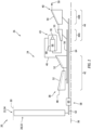
- FIG. 1 illustrates a powerplant 20 for an aircraft.
- the aircraft may be an airplane, a helicopter, a drone (e.g., an unmanned aerial vehicle (UAV)) or any other manned or unmanned aerial vehicle or system.
- the powerplant 20 may be configured as, or otherwise included as part of, a propulsion system for the aircraft.
- the powerplant 20 may also or alternatively be configured as, or otherwise included as part of, an electrical power system for the aircraft.
- the powerplant 20 of the present application is not limited to aircraft applications.
- the powerplant 20, for example, may alternatively be configured as, or otherwise included as part of, an industrial gas turbine engine for a land-based electrical powerplant.
- the powerplant 20 of FIG. 1 includes a mechanical load 22 and a core 24 of a gas turbine engine 26.
- the mechanical load 22 may be configured as or otherwise include a rotor 28 mechanically driven and/or otherwise powered by the engine core 24.
- This driven rotor 28 may be a bladed propulsor rotor (e.g., an air mover) where the powerplant 20 is (or is part of) the aircraft propulsion system.
- the propulsor rotor may be an open (e.g., un-ducted) propulsor rotor or a ducted propulsor rotor housed within a duct 30; e.g., a fan duct.
- Examples of the open propulsor rotor include a propeller rotor for a turboprop gas turbine engine, a rotorcraft rotor (e.g., a main helicopter rotor) for a turboshaft gas turbine engine, a propfan rotor for a propfan gas turbine engine, and a pusher fan rotor for a pusher fan gas turbine engine.
- An example of the ducted propulsor rotor is a fan rotor 32 for a turbofan gas turbine engine. The present disclosure, however, is not limited to the foregoing exemplary propulsor rotor arrangements.
- the driven rotor 28 may alternatively be a generator rotor of an electric power generator where the powerplant 20 is (or is part of) the aircraft power system; e.g., an auxiliary power unit (APU) for the aircraft.
- the mechanical load 22 is described below as a fan section 34 of the gas turbine engine 26, and the driven rotor 28 is described below as the fan rotor 32 within the fan section 34.
- the gas turbine engine 26 extends axially along an axis 36 between and to an upstream end of the gas turbine engine 26 and a downstream end of the gas turbine engine 26.
- This axis 36 may be a centerline axis of any one or more of the powerplant members 24, 26 and 28.
- the axis 36 may also or alternatively be a rotational axis of one or more rotating assemblies (e.g., 38 and 40) of the gas turbine engine 26 and its engine core 24.
- the engine core 24 includes a compressor section 42, a combustor section 43, a turbine section 44 and a core flowpath 46.
- the turbine section 44 includes a high pressure turbine (HPT) section 44A and a low pressure turbine (LPT) section 44B; e.g., a power turbine (PT) section.
- the core flowpath 46 extends sequentially, longitudinally through the compressor section 42, the combustor section 43, the HPT section 44A and the LPT section 44B from an airflow inlet 48 into the core flowpath 46 to a combustion products exhaust 50 from the core flowpath 46.
- the core inlet 48 of FIG. 1 is disposed towards the engine upstream end, downstream of the fan section 34 and its fan rotor 32.
- the core exhaust 50 of FIG. 1 is disposed at (e.g., on, adjacent or proximate) or otherwise towards the engine downstream end.
- Each of the engine sections 42, 44A and 44B includes one or more respective bladed rotors 52-54.
- the compressor rotors 52 are coupled to and rotatable with the HPT rotor 53.
- the compressor rotors 52 of FIG. 1 are connected to the HPT rotor 53 by a high speed shaft 56.
- At least (or only) the compressor rotors 52, the HPT rotor 53 and the high speed shaft 56 collectively form the high speed rotating assembly 38; e.g., a high speed spool.
- the fan rotor 32 is coupled to and rotatable with the LPT rotor 54.
- the fan rotor 32 of FIG. 1 is connected to the LPT rotor 54 by a drivetrain 58.
- This drivetrain 58 may be configured as a geared drivetrain.
- the fan rotor 32 of FIG. 1 for example, is connected to a geartrain 60 by a fan shaft 62, where the geartrain 60 may be an epicyclic geartrain or another type of gear system and/or transmission.
- the geartrain 60 is connected to the LPT rotor 54 through a low speed shaft 64. With this arrangement, the LPT rotor 54 may rotate at a different (e.g., faster) speed than the fan rotor 32 (the driven rotor 28). At least (or only) the fan rotor 32, the LPT rotor 54, the engine shafts 62 and 64 and the geartrain 60 collectively form the low speed rotating assembly 40.
- the drivetrain 58 may alternatively be configured as a direct drive system where the geartrain 60 is omitted and the LPT rotor 54 and the fan rotor 32 (the driven rotor 28) rotate at a common (the same) speed.
- each of the rotating assemblies 38 and 40 and its members may be rotatable about the axis 36.
- air may be directed across the fan rotor 32 and into the engine core 24 through the core inlet 48.
- This air entering the core flowpath 46 may be referred to as "core air”.
- the core air is compressed by the compressor rotors 52 and directed into a combustion chamber 66 (e.g., an annular combustion chamber) within a combustor 68 (e.g., an annular combustor) of the combustor section 43.
- Fuel is injected into the combustion chamber 66 by one or more fuel injectors 70 and mixed with the compressed core air to provide a fuel-air mixture.
- This fuel-air mixture is ignited and combustion products thereof flow through and sequentially cause the HPT rotor 53 and the LPT rotor 54 to rotate.
- the rotation of the HPT rotor 53 drives rotation of the compressor rotors 52 and, thus, the compression of the air received from the core inlet 48.
- the rotation of the LPT rotor 54 drives rotation of the fan rotor 32 (the driven rotor 28).
- the driven rotor 28 is configured as the propulsor rotor
- the rotation of that propulsor rotor may propel additional air (e.g., outside air, bypass air, etc.) outside of the engine core 24 to provide aircraft thrust and/or lift.
- the rotation of the fan rotor 32 for example, propels bypass air through a bypass flowpath outside of the engine core 24 to provide aircraft thrust.
- the driven rotor 28 is configured as the generator rotor, the rotation of that generator rotor may facilitate generation of electricity.
- the gas turbine engine 26 is described above with an exemplary arrangement of engine sections 34, 42, 43, 44A and 44B and an exemplary arrangement of rotating assemblies 38 and 40.
- the present disclosure is not limited to such exemplary arrangements.
- the compressor section 42 may include a low pressure compressor (LPC) section and a high pressure compressor (HPC) section, where one or more of the compressor rotors 52 may be disposed in the HPC section and the LPC section may include a low pressure compressor (LPC) rotor coupled to the LPT rotor 54 through the low speed shaft 64.
- the gas turbine engine 26 and its engine core 24 may include a single rotating assembly (e.g., spool), or more than two rotating assemblies (e.g., spools).
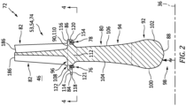
- FIG. 2 illustrates a rotor assembly 72 for the gas turbine engine 26 and its engine core 24.
- This rotor assembly 72 includes an integrally bladed rotor (IBR) 74 and one or more annular dampers 76 and 78; e.g., damper rings.
- IBR integrally bladed rotor
- the rotor disk 80 extends axially along the axis 36 between and to an axial upstream side 84 of the bladed rotor 74 and its rotor disk 80 and an axial downstream side 86 of the bladed rotor 74 and its rotor disk 80.
- the rotor upstream side 84 is upstream of the rotor downstream side 86 along the core flowpath 46.
- the rotor disk 80 extends radially from a radial inner side 88 of the bladed rotor 74 and its rotor disk 80 to a radial outer side 90 of the rotor disk 80.
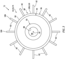
- the rotor disk 80 extends circumferentially about the axis 36 providing the rotor disk 80 with a full-hoop (e.g., annular) geometry; see also FIG. 3 .
- the rotor disk 80 of FIG. 2 includes an annular disk hub 92, an annular disk web 94 and an annular disk rim 96.
- the disk hub 92 may form an inner mass of the rotor disk 80.
- the disk hub 92 is disposed at the rotor inner side 88 and forms a radial inner periphery of the bladed rotor 74 and its rotor disk 80.
- the disk hub 92 of FIG. 2 thereby forms and circumscribes an inner bore 98 of the bladed rotor 74, which inner bore 98 extends axially along the axis 36 through the bladed rotor 74 and its rotor disk 80.
- the disk hub 92 extends axially along the axis 36 between and to opposing axial sides 100 and 102 of the disk hub 92.
- the disk web 94 is radially between and connects the disk hub 92 and the disk rim 96.
- the disk web 94 of FIG. 2 projects radially out from (in an outward direction away from the axis 36) the disk hub 92 to the disk rim 96.
- This disk web 94 is formed integral with the disk hub 92 and the disk rim 96.
- the disk web 94 extends axially along the axis 36 between and to opposing axial sides 104 and 106 of the disk web 94.
- the web upstream side 104 may be axially recessed from the hub upstream side 100.
- the web downstream side 106 may be axially recessed from the hub downstream side 102.
- An axial width of the disk web 94 may thereby be different (e.g., thinner) than an axial width of the disk hub 92.
- the present disclosure is not limited to such an exemplary arrangement.
- the disk rim 96 is disposed at the disk outer side 90 and forms a radial outer periphery of the rotor disk 80.
- This disk rim 96 of FIG. 2 also forms a radial inner platform 108 of the bladed rotor 74.
- a radial outer surface 110 of the inner platform 108 forms an inner peripheral boundary of the core flowpath 46 longitudinally (e.g., axially in FIG. 2 ) across the bladed rotor 74.
- the disk rim 96 of FIG. 2 includes a rim base 112, an axial upstream flange 114 and an axial downstream flange 116.
- the rim base 112 is axially aligned with and radially outboard of the disk web 94. This rim base 112 connects the upstream flange 114 and the downstream flange 116 to the disk web 94.
- the upstream flange 114 projects axially along the axis 36 (in an upstream direction along the core flowpath 46) out from the rim base 112 and the disk web 94 to an axial distal end 118 of the upstream flange 114 at the rotor upstream side 84.
- the downstream flange 116 projects axially along the axis 36 (in a downstream direction along the core flowpath 46) out from the rim base 112 and the disk web 94 to an axial distal end 120 of the downstream flange 116 at the rotor downstream side 86.
- the rim members 112, 114 and 116 collectively form the inner platform 108 and its platform outer surface 110. More particularly, the upstream flange 114 forms an axial upstream section of the platform outer surface 110.
- the downstream flange 116 forms an axial downstream section of the platform outer surface 110.
- the rim base 112 forms an axial intermediate section of the platform outer surface 110 extending axially between the upstream section of the platform outer surface 110 and the downstream section of the platform outer surface 110.
- the upstream flange 114 extends radially from a radial inner side 121 of the upstream flange 114 to the platform outer surface 110 at a radial outer side 122 of the upstream flange 114; see also FIG. 5 .
- the upstream flange 114 extends circumferentially around the axis 36 providing the upstream flange 114 with a full-hoop (e.g., annular) geometry.
- the disk rim 96 and its upstream flange 114 include an annular upstream groove 124 and a plurality of upstream slots 126 (e.g., scallops, pockets, etc.), where each of these upstream apertures 124 and 128 is formed by the upstream flange 114 at its upstream flange inner side 121.
- upstream slots 126 e.g., scallops, pockets, etc.
- the upstream groove 124 extends circumferentially around the axis 36 within the upstream flange 114.
- the upstream groove 124 extends axially along the axis 36 within the upstream flange 114 between opposing axial groove side surfaces 128 and 130 of the upstream flange 114.
- the upstream groove side surface 128 forms an axial upstream side of the upstream groove 124 within the upstream flange 114.
- the downstream groove side surface 130 forms an axial downstream side of the upstream groove 124 within the upstream flange 114.
- the upstream groove 124 projects radially into the upstream flange 114 (in the outward direction away from the axis 36) from the upstream flange inner side 121 to a (e.g., circumferentially segmented) radial outer groove end surface 132.
- This groove end surface 132 of FIG. 5 extends axially along the axis 36 between and to the groove side surfaces 128 and 130.
- the groove end surface 132 forms a radial distal outer end of the upstream groove 124 within the upstream flange 114.
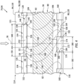
- the upstream slots 126 are arranged (e.g., equispaced) circumferentially about the axis 36 and along the upstream groove 124 in an annular array; e.g., a circular array. Each of these upstream slots 126 axially intersects the upstream groove 124.
- Each upstream slot 126 of FIG. 4 extends axially across the upstream groove 124 and between a respective set of opposing axial slot end surfaces 134 and 136 of the upstream flange 114.
- the upstream slot end surface 134 forms an axial upstream end of a respective one of the upstream slots 126 within the upstream flange 114.
- each upstream slot 126 of FIG. 4 includes an axial upstream slot section 138 (e.g., a notch), an axial downstream slot section 140 (e.g., a notch) and an axial intermediate slot section 142 (e.g., a channel).
- the upstream slot section 138 projects axially along the axis 36 into the upstream flange 114 from the upstream groove side surface 128 to its respective upstream slot end surface 134.
- the downstream slot section 140 projects axially along the axis 36 into the upstream flange 114 from the downstream groove side surface 130 to its respective downstream slot end surface 136.
- the intermediate slot section 142 extends axially along the axis 36 within the upstream flange 114 and across the upstream groove 124 from the upstream slot section 138 to the downstream slot section 140. In other embodiments, however, it is contemplated the intermediate slot section 142 may be omitted.
- Each upstream slots 126 and its respective sections 138, 140 and 142 extends laterally (e.g., circumferentially) within the upstream flange 114 between lateral opposing sides 144 and 146 of the respective upstream slot 126.
- Each upstream slot 126 of FIG. 4 has a lateral width 148 extending between its respective lateral opposing sides 144 and 146, which upstream slot width 148 may be measured at the upstream flange inner side 121.
- Each laterally neighboring (e.g., adjacent) pair of the upstream slots 126 is laterally separated by a respective (e.g., continuous) portion of the upstream flange 114 at the upstream flange inner side 121.
- Each laterally neighboring pair of the upstream slots 126 is thereby laterally separated by a lateral distance 150. This inter-upstream slot distance 150 may be different (e.g., less) than the upstream slot width 148.
- each upstream slots 126 and its respective sections 138 and 140 projects radially into the upstream flange 114 (in the outward direction away from the axis 36) from the upstream flange inner side 121 to a radial outer distal side 152 of the respective upstream slot 126.
- the intermediate slot section 142 may also project radially into the upstream flange 114 from the groove end surface 132 to the outer distal side 152 of the respective upstream slot 126.
- each upstream slot 126 and its intermediate slot section 142 may project further radially into the upstream flange 114 from the upstream groove 124.
- the upstream slots 126 are configured to change a structural stiffness of the upstream flange 114 along the upstream groove 124.
- the downstream flange 116 extends radially from a radial inner side 154 of the downstream flange 116 to the platform outer surface 110 at a radial outer side 156 of the downstream flange 116.
- the downstream flange 116 extends circumferentially around the axis 36 providing the downstream flange 116 with a full-hoop (e.g., annular) geometry.
- the disk rim 96 and its downstream flange 116 include an annular downstream groove 158 and a plurality of downstream slots 160 (e.g., scallops, pockets, etc.), where each of these downstream apertures 158 and 160 is formed by the downstream flange 116 at its downstream flange inner side 154.
- the downstream groove 158 extends circumferentially around the axis 36 within the downstream flange 116.
- the downstream groove 158 extends axially along the axis 36 within the downstream flange 116 between opposing axial groove side surfaces 162 and 164 of the downstream flange 116.
- the upstream groove side surface 162 forms an axial upstream side of the downstream groove 158 within the downstream flange 116.
- the downstream groove side surface 164 forms an axial downstream side of the downstream groove 158 within the downstream flange 116.
- the downstream groove 158 projects radially into the downstream flange 116 (in the outward direction away from the axis 36) from the downstream flange inner side 154 to a (e.g., circumferentially segmented) radial outer groove end surface 166.
- This groove end surface 166 of FIG. 5 extends axially along the axis 36 between and to the groove side surfaces 162 and 164.
- the groove end surface 166 forms a radial distal outer end of the downstream groove 158 within the downstream flange 116.
- the downstream slots 160 are arranged (e.g., equispaced) circumferentially about the axis 36 and along the downstream groove 158 in an annular array; e.g., a circular array. Each of these downstream slots 160 axially intersects the downstream groove 158.
- Each downstream slot 160 of FIG. 4 for example, extends axially across the downstream groove 158 and between the downstream flange distal end 120 and an axial slot end surface 168 of the downstream flange 116.
- the slot end surface 168 forms an axial upstream end of a respective one of the downstream slots 160 within the downstream flange 116.
- An axial downstream end of a respective one of the downstream slots 160 is defined at the downstream flange distal end 120.
- each downstream slot 160 projects axially along the axis 36 into the downstream flange 116 from the downstream flange distal end 120 (across the downstream groove 158) to the respective slot end surface 168.
- Each downstream slot 160 of FIG. 4 includes an axial upstream slot section 170 (e.g., a notch), an axial downstream slot section 172 (e.g., a channel) and an axial intermediate slot section 174 (e.g., a channel).
- the upstream slot section 170 projects axially along the axis 36 into the downstream flange 116 from the upstream groove side surface 162 to its respective slot end surface 168.
- the downstream slot section 172 projects axially along the axis 36 into the downstream flange 116 from the downstream groove side surface 164 to the downstream flange distal end 120.
- the intermediate slot section 174 extends axially along the axis 36 within the downstream flange 116 and across the downstream groove 158 from the upstream slot section 170 to the downstream slot section 172. In other embodiments, however, it is contemplated the intermediate slot section 174 may be omitted.
- Each downstream slots 160 and its respective sections 170, 172 and 174 extend laterally (e.g., circumferentially) within the downstream flange 116 between lateral opposing sides 176 and 178 of the respective downstream slot 160.
- Each downstream slot 160 of FIG. 4 has a lateral width 180 extending between its respective lateral opposing sides 176 and 178, which downstream slot width 180 may be measured at the downstream flange inner side 154.
- the downstream slot width 180 may be different (e.g., less) than the upstream slot width 148.
- Each laterally neighboring (e.g., adjacent) pair of the downstream slots 160 is laterally separated by a respective (e.g., continuous) portion of the downstream flange 116 at the downstream flange inner side 154.
- Each laterally neighboring pair of the downstream slots 160 is thereby laterally separated by a lateral distance 182.
- This inter-downstream slot distance 182 may be equal to or different than the downstream slot width 180.
- the inter-downstream slot distance 182 may be different (e.g., greater) than the inter-upstream slot distance 150.
- each downstream slots 160 and its respective sections 170 and 172 projects radially into the downstream flange 116 (in the outward direction away from the axis 36) from the downstream flange inner side 154 to a radial outer distal side 184 of the respective downstream slot 160.
- the intermediate slot section 174 may also project radially into the downstream flange 116 from the groove end surface 166 to the outer distal side 184 of the respective downstream slot 160.
- each downstream slot 160 and its intermediate slot section 174 may project further radially into the downstream flange 116 from the downstream groove 158.
- the downstream slots 160 are configured to change a structural stiffness of the downstream flange 116 along the downstream groove 158.
- the rotor blades 82 are arranged circumferentially about the axis 36 in an annular array; e.g., a circular array.
- This array of rotor blades 82 is disposed radially outboard of and circumscribes the rotor disk 80 and its inner platform 108.
- Each rotor blade 82 is configured as an airfoil which projects radially (e.g., spanwise) out from the rotor disk 80 and its platform outer surface 110 to a tip 186 of the respective rotor blade 82.
- Each of the rotor blades 82 is formed integral with the rotor disk 80.
- the bladed rotor 74 more particularly, is formed as a single unitary body.
- a traditional bladed rotor includes rotor blades which are mechanically attached to a rotor disk through, for example, dovetail interfaces, firtree interfaces or other removeable attachments.
- each rotor blade 82 and its airfoil extends along a camber line 188 between and to an upstream leading edge 190 of the rotor blade 82 and its airfoil and a downstream trailing edge 192 of the rotor blade 82 and its airfoil.
- Each rotor blade 82 and its airfoil extends laterally between and to a first (e.g., concave, pressure) side 194 of the rotor blade 82 and its airfoil and a second (e.g., convex, suction) side 196 of the rotor blade 82 and its airfoil.
- the bladed rotor 74 includes a quantity X of the rotor blades 82, a quantity Y of the upstream slots 126, and a quantity Z of the downstream slots 160.
- the quantity Y may be equal to the quantity X divided by a first integer N1 (e.g., 1, 2, 3, etc.).
- the quantity Z may be equal to the quantity X divided by a second integer N2 (e.g., 1, 2, 3, etc.), where second integer N2 may be equal to or different than first integer N1.
- first integer N1 e.g., 1, 2, 3, etc.
- second integer N2 e.g., 1, 2, 3, etc.
- second integer N2 may be equal to or different than first integer N1.
- the upstream slots 126 are configured as local strain amplifiers.
- the quantity Y of the upstream slots 126, the upstream slot width 148 and/or the locations of the upstream slots 126 relative to the rotor blades 82 may thereby be selected to selectively amplify a circumferential strain gradient in the upstream flange 114.
- the upstream slots 126 may be sized and arranged such that circumferential strains at the upstream slot locations are less than seventy-five percent (75%) of a maximum strain along the upstream groove 124 if there were no upstream slots 126.
- each upstream slot 126 of FIG. 4 is circumferentially offset from (e.g., does not circumferentially overlap) the leading edge 190 of the respective associated rotor blade 82.
- the present disclosure is not limited to such an exemplary arrangement.
- the downstream slots 160 are configured as local strain amplifiers.
- the quantity Z of the downstream slots 160, the downstream slot width 180 and/or the locations of the downstream slots 160 relative to the rotor blades 82 may thereby be selected to selectively amplify a circumferential strain gradient in the downstream flange 116.
- the downstream slots 160 may be sized and arranged such that circumferential strains at the downstream slot locations are less than seventy-five percent (75%) of a maximum strain along the downstream groove 158 if there were no downstream slots 160.
- Each downstream slot 160 of FIG. 4 may be circumferentially associated with (e.g., aligned with, overlap, etc.) a respective one of the rotor blades 82 and its airfoil.
- each downstream slot 160 of FIG. 4 is circumferentially offset from (e.g., does not circumferentially overlap) the trailing edge 192 of the respective associated rotor blade 82.
- the present disclosure is not limited to such an exemplary arrangement.
- the upstream damper 76 extends circumferentially about (e.g., completely around) the axis 36.
- the upstream damper 76 is arranged axially between the disk web 94 and the rotor upstream side 84.
- This upstream damper 76 is mounted to the rotor disk 80 and seated within the upstream groove 124.
- the upstream damper 76 of FIG. 6 for example, is spring loaded into the upstream groove 124 to maintain contact between the upstream damper 76 and the upstream flange 114 while facilitating relative circumferential shifting between the upstream damper 76 and the upstream flange 114.
- the upstream damper 76 projects radially (in the outward direction away from the axis 36) into the upstream groove 124 and may radially engage (e.g., contact, abut against, be biased against, etc.) the groove end surface 132.
- the upstream damper 76 may also axially engage one of the groove side surfaces 128 and 130.
- an axial width of the upstream damper 76 is sized (e.g., slightly) smaller than an axial width of the upstream groove 124 between the groove side surfaces 128 and 130.
- the upstream damper 76 is operable to move (e.g., slightly shift) within the upstream groove 124 during rotation of the bladed rotor 74 to provide vibration damping.
- the downstream damper 78 extends circumferentially about (e.g., completely around) the axis 36.
- the downstream damper 78 is arranged axially between the disk web 94 and the rotor downstream side 86.
- This downstream damper 78 is mounted to the rotor disk 80 and seated within the downstream groove 158.
- the downstream damper 78 of FIG. 6 is spring loaded into the downstream groove 158 to maintain contact between the downstream damper 78 and the downstream flange 116 while facilitating relative circumferential shifting between the downstream damper 78 and the downstream flange 116.
- the downstream damper 78 projects radially (in the outward direction away from the axis 36) into the downstream groove 158 and may radially engage (e.g., contact, abut against, be biased against, etc.) the groove end surface 166.
- the downstream damper 78 may also axially engage one of the groove side surfaces 162 and 164.
- an axial width of the downstream damper 78 is sized (e.g., slightly) smaller than an axial width of the downstream groove 158 between the groove side surfaces 162 and 164.
- the downstream damper 78 is operable to move (e.g., slightly shift) within the downstream groove 158 during rotation of the bladed rotor 74 to provide vibration damping.
- the bladed rotor 74 may be subject to various bending modes. These bending modes include, but are not limited to:
- the bladed rotor 74 includes both the upstream damper 76 and the downstream damper 78. In other embodiments, however, the bladed rotor 74 may be configured without (a) the upstream damper 76 and, thus, the upstream groove 124 and the upstream slots 126, or (b) the downstream damper 78 and, thus, the downstream groove 158 and the downstream slots 160.
- each upstream slot 126 may have a different configuration than each downstream slot 160.
- the upstream slots 126 of FIGS. 4 and 5 for example, extend axially within and are axially bounded within the upstream flange 114 whereas the downstream slots 160 project axially into the upstream flange 114. In other embodiments, however, these configurations may be reversed, or both the upstream slots 126 and the downstream slots 160 may have common (the same) configurations.
- each slot 126, 160 has peripheral geometry when viewed in a reference plane, for example, perpendicular to the axis 36 (see FIGS. 4 and 5 ).
- This peripheral geometry may be curved (e.g., see FIG. 7A ) or polygonal (e.g., see FIG. 7B ).
- Examples of the curved peripheral geometry include a partial circular geometry, a partial oval geometry, a splined geometry, etc.
- Examples of the polygonal peripheral geometry include a partial rectangular geometry, a partial trapezoidal geometry, etc. The present disclosure, however, is not limited to the foregoing exemplary slot geometries.
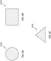
- each damper 76, 78 has a cross-sectional geometry when viewed in a reference plane, for example, parallel with (e.g., including) the axis 36 (see FIG. 6 ).
- This cross-sectional geometry may be rounded (e.g., see FIG. 8A ) or polygonal (e.g., see FIGS. 8B and 8C ).
- Examples of the rounded cross-sectional geometry include a circular geometry, an oval geometry, etc.
- Examples of the polygonal cross-sectional geometry include a square geometry, a rectangular geometry, a tapered (e.g., triangular, trapezoidal, etc.) geometry, etc.
- each damper 76, 78 may be configured as a single unitary body. In other embodiments, each damper 76, 78 may include multiple bodies.
- each damper 76, 78 may be constructed from metal; e.g., a nickel (Ni) based material. This metal may be the same material as or a different material than metal forming the bladed rotor 74.
- the damper(s) 76, 78 of the present disclosure are not limited to any particular material construction.
- damper(s) 76, 78 are described above with respect to the integrally bladed rotor 74, the present disclosure is not limited thereto. It is contemplated, for example, the damper(s) 76, 78 and the associated slotted grooves (e.g., elements 124 and 126, 158 and 160) may also provide damping for a bladed rotor (e.g., the HPT rotor 53 or the LPT rotor 54) with mechanical attachments removably securing its rotor blades to its rotor disk.
- a bladed rotor e.g., the HPT rotor 53 or the LPT rotor 54
Landscapes
- Engineering & Computer Science (AREA)
- Mechanical Engineering (AREA)
- General Engineering & Computer Science (AREA)
- Ceramic Engineering (AREA)
- Turbine Rotor Nozzle Sealing (AREA)
Abstract
Description
- This disclosure relates generally to a gas turbine engine and, more particularly, to a bladed rotor for the gas turbine engine.
- A gas turbine engine includes multiple bladed rotors. Various types and configurations of bladed rotors are known in the art, including integrally bladed rotors (IBRs). While these known bladed rotors have various benefits, there is still room in the art for improvement.
- According to an aspect of the present invention, an assembly is provided for a gas turbine engine. This assembly includes an integrally bladed rotor and a damper. The integrally bladed rotor is rotatable about an axis. The integrally bladed rotor includes a plurality of rotor blades and a rotor disk. The rotor blades are arranged circumferentially around and project radially out from the rotor disk. The rotor disk includes a flange, a groove and a plurality of slots. The groove extends circumferentially around the axis within the flange. The groove projects radially into the flange from an inner (e.g. radially inner) side of the flange. The slots are arranged circumferentially about the axis along the groove. Each of the slots projects radially into the flange from the inner side of the flange. The damper is mounted to the rotor disk and seated within the groove.
- In an embodiment of the above, the integrally bladed rotor may be configured as a turbine rotor for the gas turbine engine.
- In an embodiment according to any of the previous embodiments, the assembly may also include a compressor section, a combustor section, a turbine section and a flowpath extending longitudinally through the compressor section, the combustor section and the turbine section from an inlet into the flowpath to an exhaust from the flowpath. The turbine section may include the integrally bladed rotor.
- In an embodiment according to any of the previous embodiments, the groove may extend axially within the flange between opposing axial groove side surfaces.
- In an embodiment according to any of the previous embodiments, the rotor blades may only include a first quantity of rotor blades. The slots may only include a second quantity of slots. The second quantity of slots may be equal to the first quantity of rotor blades divided by an integer N.
- In an embodiment according to any of the previous embodiments, the integer N may be equal to one.
- In an embodiment according to any of the previous embodiments, each of the slots may be circumferentially aligned with a respective one of the rotor blades.
- In an embodiment according to any of the previous embodiments, each of the slots may be circumferentially offset from a leading edge or a trailing edge of the respective one of the rotor blades.
- In an embodiment according to any of the previous embodiments, each of the slots may axially intersect the groove.
- In an embodiment according to any of the previous embodiments, each of the slots may extend axially across the groove.
- In an embodiment according to any of the previous embodiments, the groove may project radially into the flange from the inner side of the flange to an outer end of the groove. Each of the slots may project radially into the flange from the outer end of the groove.
- In an embodiment according to any of the previous embodiments, the slots may include a first slot. The first slot may project axially into the flange from an end of the flange.
- In an embodiment according to any of the previous embodiments, the slots may include a first slot. The first slot may extend axially within the flange between opposing axial slot end surfaces.
- In an embodiment according to any of the previous embodiments, the slots may include a first slot. The first slot may include a first slot section and a second slot section circumferentially aligned with the first slot section. The first slot section may extend axially into the flange from a first side of the groove. The second slot section may extend axially into the flange from a second side of the groove.
- In an embodiment according to any of the previous embodiments, the slots may include a first slot. The first slot may have a curved peripheral geometry in a plane perpendicular to the axis.
- In an embodiment according to any of the previous embodiments, each laterally neighboring pair of the slots may be laterally separated by a respective portion of the flange at the inner side of the flange.
- In an embodiment according to any of the previous embodiments, the rotor disk may also include a web. The damper may be arranged axially between the web and an upstream side of the integrally bladed rotor.
- In an embodiment according to any of the previous embodiments, the rotor disk may also include a web. The damper may be arranged axially between the web and a downstream side of the integrally bladed rotor.
- In an embodiment according to any of the previous embodiments, the assembly may also include a second damper mounted to the rotor disk. The second damper may be arranged axially between the web and an upstream side of the integrally bladed rotor.
- In an embodiment according to any of the previous embodiments, the rotor disk may also include a platform. The rotor blades may project radially out from the platform. The platform may include the flange.
- According to another aspect of the present invention, another assembly is provided for a gas turbine engine. This assembly includes a rotor and a damper ring. The rotor is rotatable about an axis. The rotor includes a rotor disk and a plurality of rotor blades. The rotor disk includes an annular flange, an annular groove and a plurality of slots axially intersecting the annular groove. The annular groove is formed in the annular flange at an inner side of the annular flange. The slots are formed in the annular flange at the inner side of the annular flange. The slots are arranged circumferentially about the axis along the annular groove. The rotor blades are connected to the rotor disk and project radially out from an outer periphery of the rotor disk. The rotor blades are arranged circumferentially about the axis in an array such that each of the slots is circumferentially associated with a respective one of the rotor blades. The damper ring is attached to the rotor disk and arranged within the groove.
- According to still another aspect of the present invention, another assembly is provided for a gas turbine engine. This assembly includes a turbine rotor and a plurality of damper rings. The turbine rotor is rotatable about an axis. The turbine rotor includes a turbine disk and a plurality of turbine blades. The turbine disk includes a web. The turbine blades are formed integral with the turbine disk and project radially out from an outer periphery of the turbine disk. The damper rings are mounted to the turbine disk. A first of the damper rings is seated in a first scalloped groove of the turbine disk axially between the web and an upstream side of the turbine rotor. A second of the damper rings is seated in a second scalloped groove of the turbine disk axially between the web and a downstream side of the turbine rotor.
- The present disclosure may include any one or more of the individual features disclosed above and/or below alone or in any combination thereof.
- The foregoing features and the operation of the invention will become more apparent in light of the following description and the accompanying drawings.
-
-
FIG. 1 is a partial side schematic illustration of a powerplant for an aircraft. -
FIG. 2 is a partial side sectional illustration of a rotor assembly. -
FIG. 3 is a schematic illustration of the rotor assembly. -
FIG. 4 is a partial sectional illustration of an integrally bladed rotor taken along line 4-4 inFIG. 2 , where rotor blades and an axis are projected onto the illustration. -
FIG. 5 is a partial sectional illustration of the bladed rotor. -
FIG. 6 is a partial sectional illustration of the rotor assembly. -
FIGS. 7A and 7B are partial sectional illustrations of the bladed rotor at a slot with various arrangements. -
FIGS. 8A-C are partial sectional illustrations of a damper with various arrangements. -
FIG. 1 illustrates apowerplant 20 for an aircraft. The aircraft may be an airplane, a helicopter, a drone (e.g., an unmanned aerial vehicle (UAV)) or any other manned or unmanned aerial vehicle or system. Thepowerplant 20 may be configured as, or otherwise included as part of, a propulsion system for the aircraft. Thepowerplant 20 may also or alternatively be configured as, or otherwise included as part of, an electrical power system for the aircraft. Thepowerplant 20 of the present application, however, is not limited to aircraft applications. Thepowerplant 20, for example, may alternatively be configured as, or otherwise included as part of, an industrial gas turbine engine for a land-based electrical powerplant. Thepowerplant 20 ofFIG. 1 includes amechanical load 22 and acore 24 of agas turbine engine 26. - The
mechanical load 22 may be configured as or otherwise include a rotor 28 mechanically driven and/or otherwise powered by theengine core 24. This driven rotor 28 may be a bladed propulsor rotor (e.g., an air mover) where thepowerplant 20 is (or is part of) the aircraft propulsion system. The propulsor rotor may be an open (e.g., un-ducted) propulsor rotor or a ducted propulsor rotor housed within aduct 30; e.g., a fan duct. Examples of the open propulsor rotor include a propeller rotor for a turboprop gas turbine engine, a rotorcraft rotor (e.g., a main helicopter rotor) for a turboshaft gas turbine engine, a propfan rotor for a propfan gas turbine engine, and a pusher fan rotor for a pusher fan gas turbine engine. An example of the ducted propulsor rotor is a fan rotor 32 for a turbofan gas turbine engine. The present disclosure, however, is not limited to the foregoing exemplary propulsor rotor arrangements. Moreover, the driven rotor 28 may alternatively be a generator rotor of an electric power generator where thepowerplant 20 is (or is part of) the aircraft power system; e.g., an auxiliary power unit (APU) for the aircraft. However, for ease of description, themechanical load 22 is described below as a fan section 34 of thegas turbine engine 26, and the driven rotor 28 is described below as the fan rotor 32 within the fan section 34. - The
gas turbine engine 26 extends axially along anaxis 36 between and to an upstream end of thegas turbine engine 26 and a downstream end of thegas turbine engine 26. Thisaxis 36 may be a centerline axis of any one or more of thepowerplant members axis 36 may also or alternatively be a rotational axis of one or more rotating assemblies (e.g., 38 and 40) of thegas turbine engine 26 and itsengine core 24. - The
engine core 24 includes acompressor section 42, acombustor section 43, aturbine section 44 and acore flowpath 46. Theturbine section 44 includes a high pressure turbine (HPT)section 44A and a low pressure turbine (LPT)section 44B; e.g., a power turbine (PT) section. Thecore flowpath 46 extends sequentially, longitudinally through thecompressor section 42, thecombustor section 43, theHPT section 44A and theLPT section 44B from anairflow inlet 48 into thecore flowpath 46 to a combustion products exhaust 50 from thecore flowpath 46. Thecore inlet 48 ofFIG. 1 is disposed towards the engine upstream end, downstream of the fan section 34 and its fan rotor 32. Thecore exhaust 50 ofFIG. 1 is disposed at (e.g., on, adjacent or proximate) or otherwise towards the engine downstream end. - Each of the
engine sections compressor rotors 52 are coupled to and rotatable with theHPT rotor 53. Thecompressor rotors 52 ofFIG. 1 , for example, are connected to theHPT rotor 53 by ahigh speed shaft 56. At least (or only) thecompressor rotors 52, theHPT rotor 53 and thehigh speed shaft 56 collectively form the highspeed rotating assembly 38; e.g., a high speed spool. The fan rotor 32 is coupled to and rotatable with theLPT rotor 54. The fan rotor 32 ofFIG. 1 , for example, is connected to theLPT rotor 54 by adrivetrain 58. Thisdrivetrain 58 may be configured as a geared drivetrain. The fan rotor 32 ofFIG. 1 , for example, is connected to ageartrain 60 by afan shaft 62, where thegeartrain 60 may be an epicyclic geartrain or another type of gear system and/or transmission. Thegeartrain 60 is connected to theLPT rotor 54 through alow speed shaft 64. With this arrangement, theLPT rotor 54 may rotate at a different (e.g., faster) speed than the fan rotor 32 (the driven rotor 28). At least (or only) the fan rotor 32, theLPT rotor 54, theengine shafts geartrain 60 collectively form the lowspeed rotating assembly 40. In other embodiments, however, thedrivetrain 58 may alternatively be configured as a direct drive system where thegeartrain 60 is omitted and theLPT rotor 54 and the fan rotor 32 (the driven rotor 28) rotate at a common (the same) speed. Referring again toFIG. 1 , each of therotating assemblies axis 36. - During operation of the
powerplant 20 and itsgas turbine engine 26, air may be directed across the fan rotor 32 and into theengine core 24 through thecore inlet 48. This air entering thecore flowpath 46 may be referred to as "core air". The core air is compressed by thecompressor rotors 52 and directed into a combustion chamber 66 (e.g., an annular combustion chamber) within a combustor 68 (e.g., an annular combustor) of thecombustor section 43. Fuel is injected into thecombustion chamber 66 by one ormore fuel injectors 70 and mixed with the compressed core air to provide a fuel-air mixture. This fuel-air mixture is ignited and combustion products thereof flow through and sequentially cause theHPT rotor 53 and theLPT rotor 54 to rotate. The rotation of theHPT rotor 53 drives rotation of thecompressor rotors 52 and, thus, the compression of the air received from thecore inlet 48. The rotation of theLPT rotor 54 drives rotation of the fan rotor 32 (the driven rotor 28). Where the driven rotor 28 is configured as the propulsor rotor, the rotation of that propulsor rotor may propel additional air (e.g., outside air, bypass air, etc.) outside of theengine core 24 to provide aircraft thrust and/or lift. The rotation of the fan rotor 32, for example, propels bypass air through a bypass flowpath outside of theengine core 24 to provide aircraft thrust. However, where the driven rotor 28 is configured as the generator rotor, the rotation of that generator rotor may facilitate generation of electricity. - For ease of description, the
gas turbine engine 26 is described above with an exemplary arrangement ofengine sections rotating assemblies compressor section 42, for example, may include a low pressure compressor (LPC) section and a high pressure compressor (HPC) section, where one or more of thecompressor rotors 52 may be disposed in the HPC section and the LPC section may include a low pressure compressor (LPC) rotor coupled to theLPT rotor 54 through thelow speed shaft 64. In another example, thegas turbine engine 26 and itsengine core 24 may include a single rotating assembly (e.g., spool), or more than two rotating assemblies (e.g., spools). -
FIG. 2 illustrates arotor assembly 72 for thegas turbine engine 26 and itsengine core 24. Thisrotor assembly 72 includes an integrally bladed rotor (IBR) 74 and one or moreannular dampers - The
bladed rotor 74 may be configured as theHPT rotor 53 or theLPT rotor 54. However, it is contemplated these teachings may also be applied to one or more of thecompressor rotors 52; seeFIG. 1 . Referring toFIG. 3 , thebladed rotor 74 is rotatable about theaxis 36. Thisbladed rotor 74 includes a rotor disk 80 (e.g., a turbine disk) and a plurality of rotor blades 82 (e.g., turbine blades). - Referring to
FIG. 2 , therotor disk 80 extends axially along theaxis 36 between and to an axialupstream side 84 of thebladed rotor 74 and itsrotor disk 80 and an axialdownstream side 86 of thebladed rotor 74 and itsrotor disk 80. Here, the rotorupstream side 84 is upstream of the rotordownstream side 86 along thecore flowpath 46. Therotor disk 80 extends radially from a radialinner side 88 of thebladed rotor 74 and itsrotor disk 80 to a radialouter side 90 of therotor disk 80. Therotor disk 80 extends circumferentially about theaxis 36 providing therotor disk 80 with a full-hoop (e.g., annular) geometry; see alsoFIG. 3 . Therotor disk 80 ofFIG. 2 includes anannular disk hub 92, anannular disk web 94 and anannular disk rim 96. - The
disk hub 92 may form an inner mass of therotor disk 80. Thedisk hub 92 is disposed at the rotorinner side 88 and forms a radial inner periphery of thebladed rotor 74 and itsrotor disk 80. Thedisk hub 92 ofFIG. 2 thereby forms and circumscribes aninner bore 98 of thebladed rotor 74, which inner bore 98 extends axially along theaxis 36 through thebladed rotor 74 and itsrotor disk 80. Thedisk hub 92 extends axially along theaxis 36 between and to opposingaxial sides disk hub 92. - The
disk web 94 is radially between and connects thedisk hub 92 and thedisk rim 96. Thedisk web 94 ofFIG. 2 , for example, projects radially out from (in an outward direction away from the axis 36) thedisk hub 92 to thedisk rim 96. Thisdisk web 94 is formed integral with thedisk hub 92 and thedisk rim 96. Thedisk web 94 extends axially along theaxis 36 between and to opposingaxial sides disk web 94. The webupstream side 104 may be axially recessed from the hubupstream side 100. The webdownstream side 106 may be axially recessed from the hubdownstream side 102. An axial width of thedisk web 94 may thereby be different (e.g., thinner) than an axial width of thedisk hub 92. The present disclosure, however, is not limited to such an exemplary arrangement. - The disk rim 96 is disposed at the disk
outer side 90 and forms a radial outer periphery of therotor disk 80. This disk rim 96 ofFIG. 2 also forms a radialinner platform 108 of thebladed rotor 74. A radial outer surface 110 of theinner platform 108 forms an inner peripheral boundary of thecore flowpath 46 longitudinally (e.g., axially inFIG. 2 ) across thebladed rotor 74. - The disk rim 96 of
FIG. 2 includes arim base 112, an axialupstream flange 114 and an axialdownstream flange 116. Therim base 112 is axially aligned with and radially outboard of thedisk web 94. Thisrim base 112 connects theupstream flange 114 and thedownstream flange 116 to thedisk web 94. Theupstream flange 114 projects axially along the axis 36 (in an upstream direction along the core flowpath 46) out from therim base 112 and thedisk web 94 to an axialdistal end 118 of theupstream flange 114 at the rotorupstream side 84. Thedownstream flange 116 projects axially along the axis 36 (in a downstream direction along the core flowpath 46) out from therim base 112 and thedisk web 94 to an axialdistal end 120 of thedownstream flange 116 at the rotordownstream side 86. With this arrangement, therim members inner platform 108 and its platform outer surface 110. More particularly, theupstream flange 114 forms an axial upstream section of the platform outer surface 110. Thedownstream flange 116 forms an axial downstream section of the platform outer surface 110. Therim base 112 forms an axial intermediate section of the platform outer surface 110 extending axially between the upstream section of the platform outer surface 110 and the downstream section of the platform outer surface 110. - The
upstream flange 114 extends radially from a radialinner side 121 of theupstream flange 114 to the platform outer surface 110 at a radialouter side 122 of theupstream flange 114; see alsoFIG. 5 . Theupstream flange 114 extends circumferentially around theaxis 36 providing theupstream flange 114 with a full-hoop (e.g., annular) geometry. Referring toFIG. 4 , thedisk rim 96 and itsupstream flange 114 include an annularupstream groove 124 and a plurality of upstream slots 126 (e.g., scallops, pockets, etc.), where each of theseupstream apertures upstream flange 114 at its upstream flangeinner side 121. - The
upstream groove 124 extends circumferentially around theaxis 36 within theupstream flange 114. Theupstream groove 124 extends axially along theaxis 36 within theupstream flange 114 between opposing axial groove side surfaces 128 and 130 of theupstream flange 114. The upstreamgroove side surface 128 forms an axial upstream side of theupstream groove 124 within theupstream flange 114. The downstreamgroove side surface 130 forms an axial downstream side of theupstream groove 124 within theupstream flange 114. Referring toFIG. 5 , theupstream groove 124 projects radially into the upstream flange 114 (in the outward direction away from the axis 36) from the upstream flangeinner side 121 to a (e.g., circumferentially segmented) radial outergroove end surface 132. Thisgroove end surface 132 ofFIG. 5 extends axially along theaxis 36 between and to the groove side surfaces 128 and 130. Thegroove end surface 132 forms a radial distal outer end of theupstream groove 124 within theupstream flange 114. - Referring to
FIG. 4 , theupstream slots 126 are arranged (e.g., equispaced) circumferentially about theaxis 36 and along theupstream groove 124 in an annular array; e.g., a circular array. Each of theseupstream slots 126 axially intersects theupstream groove 124. Eachupstream slot 126 ofFIG. 4 , for example, extends axially across theupstream groove 124 and between a respective set of opposing axial slot end surfaces 134 and 136 of theupstream flange 114. The upstreamslot end surface 134 forms an axial upstream end of a respective one of theupstream slots 126 within theupstream flange 114. The downstreamslot end surface 136 forms an axial downstream end of a respective one of theupstream slots 126 within theupstream flange 114. More particularly, eachupstream slot 126 ofFIG. 4 includes an axial upstream slot section 138 (e.g., a notch), an axial downstream slot section 140 (e.g., a notch) and an axial intermediate slot section 142 (e.g., a channel). Theupstream slot section 138 projects axially along theaxis 36 into theupstream flange 114 from the upstreamgroove side surface 128 to its respective upstreamslot end surface 134. Thedownstream slot section 140 projects axially along theaxis 36 into theupstream flange 114 from the downstreamgroove side surface 130 to its respective downstreamslot end surface 136. Theintermediate slot section 142 extends axially along theaxis 36 within theupstream flange 114 and across theupstream groove 124 from theupstream slot section 138 to thedownstream slot section 140. In other embodiments, however, it is contemplated theintermediate slot section 142 may be omitted. - Each
upstream slots 126 and itsrespective sections upstream flange 114 between lateral opposingsides upstream slot 126. Eachupstream slot 126 ofFIG. 4 has alateral width 148 extending between its respectivelateral opposing sides upstream slot width 148 may be measured at the upstream flangeinner side 121. Each laterally neighboring (e.g., adjacent) pair of theupstream slots 126 is laterally separated by a respective (e.g., continuous) portion of theupstream flange 114 at the upstream flangeinner side 121. Each laterally neighboring pair of theupstream slots 126 is thereby laterally separated by alateral distance 150. Thisinter-upstream slot distance 150 may be different (e.g., less) than theupstream slot width 148. - Referring to
FIG. 5 , eachupstream slots 126 and itsrespective sections inner side 121 to a radial outerdistal side 152 of the respectiveupstream slot 126. Here, theintermediate slot section 142 may also project radially into theupstream flange 114 from thegroove end surface 132 to the outerdistal side 152 of the respectiveupstream slot 126. Thus, eachupstream slot 126 and itsintermediate slot section 142 may project further radially into theupstream flange 114 from theupstream groove 124. With the above-described arrangement, theupstream slots 126 are configured to change a structural stiffness of theupstream flange 114 along theupstream groove 124. - The
downstream flange 116 extends radially from a radialinner side 154 of thedownstream flange 116 to the platform outer surface 110 at a radialouter side 156 of thedownstream flange 116. Thedownstream flange 116 extends circumferentially around theaxis 36 providing thedownstream flange 116 with a full-hoop (e.g., annular) geometry. Referring toFIG. 4 , thedisk rim 96 and itsdownstream flange 116 include an annulardownstream groove 158 and a plurality of downstream slots 160 (e.g., scallops, pockets, etc.), where each of thesedownstream apertures downstream flange 116 at its downstream flangeinner side 154. - The
downstream groove 158 extends circumferentially around theaxis 36 within thedownstream flange 116. Thedownstream groove 158 extends axially along theaxis 36 within thedownstream flange 116 between opposing axial groove side surfaces 162 and 164 of thedownstream flange 116. The upstreamgroove side surface 162 forms an axial upstream side of thedownstream groove 158 within thedownstream flange 116. The downstreamgroove side surface 164 forms an axial downstream side of thedownstream groove 158 within thedownstream flange 116. Referring toFIG. 5 , thedownstream groove 158 projects radially into the downstream flange 116 (in the outward direction away from the axis 36) from the downstream flangeinner side 154 to a (e.g., circumferentially segmented) radial outergroove end surface 166. Thisgroove end surface 166 ofFIG. 5 extends axially along theaxis 36 between and to the groove side surfaces 162 and 164. Thegroove end surface 166 forms a radial distal outer end of thedownstream groove 158 within thedownstream flange 116. - Referring to
FIG. 4 , thedownstream slots 160 are arranged (e.g., equispaced) circumferentially about theaxis 36 and along thedownstream groove 158 in an annular array; e.g., a circular array. Each of thesedownstream slots 160 axially intersects thedownstream groove 158. Eachdownstream slot 160 ofFIG. 4 , for example, extends axially across thedownstream groove 158 and between the downstream flangedistal end 120 and an axialslot end surface 168 of thedownstream flange 116. Theslot end surface 168 forms an axial upstream end of a respective one of thedownstream slots 160 within thedownstream flange 116. An axial downstream end of a respective one of thedownstream slots 160 is defined at the downstream flangedistal end 120. More particularly, eachdownstream slot 160 projects axially along theaxis 36 into thedownstream flange 116 from the downstream flange distal end 120 (across the downstream groove 158) to the respectiveslot end surface 168. Eachdownstream slot 160 ofFIG. 4 includes an axial upstream slot section 170 (e.g., a notch), an axial downstream slot section 172 (e.g., a channel) and an axial intermediate slot section 174 (e.g., a channel). Theupstream slot section 170 projects axially along theaxis 36 into thedownstream flange 116 from the upstreamgroove side surface 162 to its respectiveslot end surface 168. Thedownstream slot section 172 projects axially along theaxis 36 into thedownstream flange 116 from the downstreamgroove side surface 164 to the downstream flangedistal end 120. Theintermediate slot section 174 extends axially along theaxis 36 within thedownstream flange 116 and across thedownstream groove 158 from theupstream slot section 170 to thedownstream slot section 172. In other embodiments, however, it is contemplated theintermediate slot section 174 may be omitted. - Each
downstream slots 160 and itsrespective sections downstream flange 116 between lateral opposingsides downstream slot 160. Eachdownstream slot 160 ofFIG. 4 has alateral width 180 extending between its respectivelateral opposing sides downstream slot width 180 may be measured at the downstream flangeinner side 154. Thedownstream slot width 180 may be different (e.g., less) than theupstream slot width 148. Each laterally neighboring (e.g., adjacent) pair of thedownstream slots 160 is laterally separated by a respective (e.g., continuous) portion of thedownstream flange 116 at the downstream flangeinner side 154. Each laterally neighboring pair of thedownstream slots 160 is thereby laterally separated by alateral distance 182. Thisinter-downstream slot distance 182 may be equal to or different than thedownstream slot width 180. Theinter-downstream slot distance 182 may be different (e.g., greater) than theinter-upstream slot distance 150. - Referring to
FIG. 5 , eachdownstream slots 160 and itsrespective sections inner side 154 to a radial outerdistal side 184 of the respectivedownstream slot 160. Here, theintermediate slot section 174 may also project radially into thedownstream flange 116 from thegroove end surface 166 to the outerdistal side 184 of the respectivedownstream slot 160. Thus, eachdownstream slot 160 and itsintermediate slot section 174 may project further radially into thedownstream flange 116 from thedownstream groove 158. With the above-described arrangement, thedownstream slots 160 are configured to change a structural stiffness of thedownstream flange 116 along thedownstream groove 158. - Referring to
FIG. 3 , therotor blades 82 are arranged circumferentially about theaxis 36 in an annular array; e.g., a circular array. This array ofrotor blades 82 is disposed radially outboard of and circumscribes therotor disk 80 and itsinner platform 108. Eachrotor blade 82 is configured as an airfoil which projects radially (e.g., spanwise) out from therotor disk 80 and its platform outer surface 110 to atip 186 of therespective rotor blade 82. Each of therotor blades 82 is formed integral with therotor disk 80. Thebladed rotor 74, more particularly, is formed as a single unitary body. Here, the term "unitary" may describe a body without severable parts. By contrast, a traditional bladed rotor includes rotor blades which are mechanically attached to a rotor disk through, for example, dovetail interfaces, firtree interfaces or other removeable attachments. - Referring to
FIG. 4 , eachrotor blade 82 and its airfoil extends along acamber line 188 between and to an upstreamleading edge 190 of therotor blade 82 and its airfoil and adownstream trailing edge 192 of therotor blade 82 and its airfoil. Eachrotor blade 82 and its airfoil extends laterally between and to a first (e.g., concave, pressure)side 194 of therotor blade 82 and its airfoil and a second (e.g., convex, suction)side 196 of therotor blade 82 and its airfoil. - The
bladed rotor 74 includes a quantity X of therotor blades 82, a quantity Y of theupstream slots 126, and a quantity Z of thedownstream slots 160. The quantity Y may be equal to the quantity X divided by a first integer N1 (e.g., 1, 2, 3, etc.). Similarly, the quantity Z may be equal to the quantity X divided by a second integer N2 (e.g., 1, 2, 3, etc.), where second integer N2 may be equal to or different than first integer N1. For example, thebladed rotor 74 ofFIG. 4 has a one-to-one (1:1) ratio between therotor blades 82 and theupstream slots 126, and a one-to-one (1:1) ratio between therotor blades 82 and thedownstream slots 160. Alternatively, there may be a two-to-one (2:1) ratio, a three-to-one (3:1) ratio, etc. between therotor blades 82 and theupstream slots 126 and/or thedownstream slots 160 in other embodiments. - The
upstream slots 126 are configured as local strain amplifiers. The quantity Y of theupstream slots 126, theupstream slot width 148 and/or the locations of theupstream slots 126 relative to therotor blades 82 may thereby be selected to selectively amplify a circumferential strain gradient in theupstream flange 114. Theupstream slots 126, for example, may be sized and arranged such that circumferential strains at the upstream slot locations are less than seventy-five percent (75%) of a maximum strain along theupstream groove 124 if there were noupstream slots 126. Eachupstream slot 126 ofFIG. 4 , for example, may be circumferentially associated with (e.g., aligned with, overlap, etc.) a respective one of therotor blades 82 and its airfoil. Here, eachupstream slot 126 ofFIG. 4 is circumferentially offset from (e.g., does not circumferentially overlap) theleading edge 190 of the respective associatedrotor blade 82. The present disclosure, however, is not limited to such an exemplary arrangement. - The
downstream slots 160 are configured as local strain amplifiers. The quantity Z of thedownstream slots 160, thedownstream slot width 180 and/or the locations of thedownstream slots 160 relative to therotor blades 82 may thereby be selected to selectively amplify a circumferential strain gradient in thedownstream flange 116. Thedownstream slots 160, for example, may be sized and arranged such that circumferential strains at the downstream slot locations are less than seventy-five percent (75%) of a maximum strain along thedownstream groove 158 if there were nodownstream slots 160. Eachdownstream slot 160 ofFIG. 4 , for example, may be circumferentially associated with (e.g., aligned with, overlap, etc.) a respective one of therotor blades 82 and its airfoil. Here, eachdownstream slot 160 ofFIG. 4 is circumferentially offset from (e.g., does not circumferentially overlap) the trailingedge 192 of the respective associatedrotor blade 82. The present disclosure, however, is not limited to such an exemplary arrangement. - Referring to
FIG. 6 , theupstream damper 76 extends circumferentially about (e.g., completely around) theaxis 36. Theupstream damper 76 is arranged axially between thedisk web 94 and the rotorupstream side 84. Thisupstream damper 76 is mounted to therotor disk 80 and seated within theupstream groove 124. Theupstream damper 76 ofFIG. 6 , for example, is spring loaded into theupstream groove 124 to maintain contact between theupstream damper 76 and theupstream flange 114 while facilitating relative circumferential shifting between theupstream damper 76 and theupstream flange 114. With this arrangement, theupstream damper 76 projects radially (in the outward direction away from the axis 36) into theupstream groove 124 and may radially engage (e.g., contact, abut against, be biased against, etc.) thegroove end surface 132. Theupstream damper 76 may also axially engage one of the groove side surfaces 128 and 130. Typically, an axial width of theupstream damper 76 is sized (e.g., slightly) smaller than an axial width of theupstream groove 124 between the groove side surfaces 128 and 130. With this arrangement, theupstream damper 76 is operable to move (e.g., slightly shift) within theupstream groove 124 during rotation of thebladed rotor 74 to provide vibration damping. - The
downstream damper 78 extends circumferentially about (e.g., completely around) theaxis 36. Thedownstream damper 78 is arranged axially between thedisk web 94 and the rotordownstream side 86. Thisdownstream damper 78 is mounted to therotor disk 80 and seated within thedownstream groove 158. Thedownstream damper 78 ofFIG. 6 , for example, is spring loaded into thedownstream groove 158 to maintain contact between thedownstream damper 78 and thedownstream flange 116 while facilitating relative circumferential shifting between thedownstream damper 78 and thedownstream flange 116. With this arrangement, thedownstream damper 78 projects radially (in the outward direction away from the axis 36) into thedownstream groove 158 and may radially engage (e.g., contact, abut against, be biased against, etc.) thegroove end surface 166. Thedownstream damper 78 may also axially engage one of the groove side surfaces 162 and 164. Typically, an axial width of thedownstream damper 78 is sized (e.g., slightly) smaller than an axial width of thedownstream groove 158 between the groove side surfaces 162 and 164. With this arrangement, thedownstream damper 78 is operable to move (e.g., slightly shift) within thedownstream groove 158 during rotation of thebladed rotor 74 to provide vibration damping. - During high speed rotation, the
bladed rotor 74 may be subject to various bending modes. These bending modes include, but are not limited to: - ▪ Mode 1: Easy wise bending such as bending from pressure to suction side and vice versa;
- ▪ Mode 2: Stiff wise bending such as bending from leading edge to trailing edge and vice versa; and
- ▪ Mode 3: Torsional bending such as airfoil twisting about its stack line.
- In some embodiments, referring to
FIG. 2 and6 , thebladed rotor 74 includes both theupstream damper 76 and thedownstream damper 78. In other embodiments, however, thebladed rotor 74 may be configured without (a) theupstream damper 76 and, thus, theupstream groove 124 and theupstream slots 126, or (b) thedownstream damper 78 and, thus, thedownstream groove 158 and thedownstream slots 160. - In some embodiments, referring to
FIGS. 4 and5 , eachupstream slot 126 may have a different configuration than eachdownstream slot 160. Theupstream slots 126 ofFIGS. 4 and5 , for example, extend axially within and are axially bounded within theupstream flange 114 whereas thedownstream slots 160 project axially into theupstream flange 114. In other embodiments, however, these configurations may be reversed, or both theupstream slots 126 and thedownstream slots 160 may have common (the same) configurations. - Referring to
FIGS. 7A and 7B , eachslot FIGS. 4 and5 ). This peripheral geometry may be curved (e.g., seeFIG. 7A ) or polygonal (e.g., seeFIG. 7B ). Examples of the curved peripheral geometry include a partial circular geometry, a partial oval geometry, a splined geometry, etc. Examples of the polygonal peripheral geometry include a partial rectangular geometry, a partial trapezoidal geometry, etc. The present disclosure, however, is not limited to the foregoing exemplary slot geometries. - Referring to
FIGS. 8A-C , eachdamper FIG. 6 ). This cross-sectional geometry may be rounded (e.g., seeFIG. 8A ) or polygonal (e.g., seeFIGS. 8B and 8C ). Examples of the rounded cross-sectional geometry include a circular geometry, an oval geometry, etc. Examples of the polygonal cross-sectional geometry include a square geometry, a rectangular geometry, a tapered (e.g., triangular, trapezoidal, etc.) geometry, etc. - In some embodiments, each
damper damper - In some embodiments, each
damper bladed rotor 74. The damper(s) 76, 78 of the present disclosure, however, are not limited to any particular material construction. - While the damper(s) 76, 78 are described above with respect to the integrally bladed
rotor 74, the present disclosure is not limited thereto. It is contemplated, for example, the damper(s) 76, 78 and the associated slotted grooves (e.g.,elements HPT rotor 53 or the LPT rotor 54) with mechanical attachments removably securing its rotor blades to its rotor disk. - While various embodiments of the present disclosure have been described, it will be apparent to those of ordinary skill in the art that many more embodiments and implementations are possible within the scope of the disclosure. For example, the present disclosure as described herein includes several aspects and embodiments that include particular features. Although these features may be described individually, it is within the scope of the present disclosure that some or all of these features may be combined with any one of the aspects and remain within the scope of the disclosure. Accordingly, the present disclosure is not to be restricted except in light of the attached claims and their equivalents.
Claims (15)
- An assembly (72) for a gas turbine engine (26), comprising:an integrally bladed rotor (74) rotatable about an axis (36), the integrally bladed rotor (74) including a plurality of rotor blades (82) and a rotor disk (80), wherein:the plurality of rotor blades (82) are arranged circumferentially around and projecting radially out from the rotor disk (80); andthe rotor disk (80) includes a flange (114, 116), a groove (124, 158) and a plurality of slots (126, 160), the groove (124, 158) extending circumferentially around the axis (36) within the flange (114, 116), the groove (124, 158) projecting radially into the flange (114, 116) from an inner side (121, 154) of the flange (114, 116), the plurality of slots (126, 160) arranged circumferentially about the axis (36) along the groove (124, 158), and each of the plurality of slots (126, 160) projecting radially into the flange (114, 116) from the inner side (121, 154) of the flange (114, 116); anda damper (76, 78) mounted to the rotor disk (80) and seated within the groove (124, 158).
- The assembly (72) of claim 1, wherein the integrally bladed rotor (74) is configured as a turbine rotor for the gas turbine engine (26).
- The assembly (72) of claim 1 or 2, wherein the groove (124, 158) extends axially within the flange (114, 116) between opposing axial groove side surfaces (128, 130, 162, 164).
- The assembly (72) of any preceding claim, wherein:the plurality of rotor blades (82) consists of a first quantity of rotor blades (82);the plurality of slots (126, 160) consists of a second quantity of slots (126, 160); andthe second quantity of slots (126, 160) is equal to the first quantity of rotor blades (82) divided by an integer N, optionally wherein the integer N is equal to one.
- The assembly (72) of any preceding claim, wherein each of the plurality of slots (126, 160) is circumferentially aligned with a respective one of the plurality of rotor blades (82), optionally wherein each of the plurality of slots (126, 160) is circumferentially offset from a leading edge (190) or a trailing edge (192) of the respective one of the plurality of rotor blades (82).
- The assembly (72) of any preceding claim, wherein:each of the plurality of slots (126, 160) axially intersects the groove (124, 158); and/oreach of the plurality of slots (126, 160) extends axially across the groove (124, 158).
- The assembly (72) of any preceding claim, wherein:the groove (124, 158) projects radially into the flange (114, 116) from the inner side (121, 154) of the flange (114, 116) to an outer end of the groove (124, 158); andeach of the plurality of slots (126, 160) projects further radially into the flange (114, 116) from the outer end (132, 166) of the groove (124, 158).
- The assembly (72) of any preceding claim, wherein:the plurality of slots (126, 160) comprises a first slot (126, 160); andthe first slot (126, 160) projects axially into the flange (114, 116) from an end (118, 120) of the flange (114, 116), and/or the first slot (126, 160) extends axially within the flange (114, 116) between opposing axial slot end surfaces (134, 136).
- The assembly (72) of any preceding claim, wherein:the plurality of slots (126, 160) comprises a or the first slot (126, 160);the first slot (126, 160) includes a first slot section (138, 170) and a second slot section (140, 172) circumferentially aligned with the first slot section (138, 170);the first slot section (138, 170) extends axially into the flange (114, 116) from a first side (128, 162) of the groove (124, 158); andthe second slot section (140, 172) extends axially into the flange (114, 116) from a second side (130, 164) of the groove (124, 158).
- The assembly (72) of any preceding claim, wherein each laterally neighboring pair of the plurality of slots (126, 160) is laterally separated by a respective portion of the flange (114, 116) at the inner side (121, 154) of the flange (114, 116).
- The assembly (72) of any preceding claim, wherein:the rotor disk (80) further includes a web (94); andthe damper (76) is arranged axially between the web (94) and an upstream side (84) of the integrally bladed rotor (74).
- The assembly (72) of any preceding claim, wherein:the rotor disk (80) further includes a or the web (94); andthe damper (78) is arranged axially between the web (94) and a downstream side (86) of the integrally bladed rotor (74), optionally further comprising:
a second damper (76) mounted to the rotor disk (80), wherein the second damper (76) is arranged axially between the web (94) and an upstream side (84) of the integrally bladed rotor (74). - The assembly (72) of any preceding claim, wherein:the rotor disk (80) further comprises a platform (110);the plurality of rotor blades (82) project radially out from the platform (110); andthe platform (110) comprises the flange (114, 116).
- An assembly (72) for a gas turbine engine (26), comprising:a rotor (74) rotatable about an axis (36), the rotor (74) including a rotor disk (80) and a plurality of rotor blades (82);the rotor disk (80) including an annular flange (114, 116), an annular groove (124, 158) and a plurality of slots (126, 160) axially intersecting the annular groove (124, 158), the annular groove (124, 158) formed in the annular flange (114, 116) at an inner side (121, 154) of the annular flange (114, 116), the plurality of slots (126, 160) formed in the annular flange (114, 116) at the inner side (121, 154) of the annular flange (114, 116), and the plurality of slots (126, 160) arranged circumferentially about the axis (36) along the annular groove (124, 158); andthe plurality of rotor blades (82) connected to the rotor disk (80) and projecting radially out from an outer periphery of the rotor disk (80), and the plurality of rotor blades (82) arranged circumferentially about the axis (36) in an array such that each of the plurality of slots (126, 160) is circumferentially associated with a respective one of the plurality of rotor blades (82); anda damper ring (76, 78) attached to the rotor disk (80) and arranged within the groove (124, 158).
- An assembly (72) for a gas turbine engine (26), comprising:a turbine rotor (74) rotatable about an axis (36), the turbine rotor (74) including a turbine disk (80) and a plurality of turbine blades (82), the turbine disk (80) comprising a web (94), and the plurality of turbine blades (82) formed integral with the turbine disk (80) and projecting radially out from an outer periphery of the turbine disk (80); anda plurality of damper rings (76, 78) mounted to the turbine disk (80), a first of the plurality of damper rings (76) seated in a first scalloped groove (124) of the turbine disk (80) axially between the web (94) and an upstream side (84) of the turbine rotor (28), and a second of the plurality of damper rings (78) seated in a second scalloped groove (158) of the turbine disk (80) axially between the web (94) and a downstream side (86) of the turbine rotor (74).
Applications Claiming Priority (1)
| Application Number | Priority Date | Filing Date | Title |
|---|---|---|---|
| US18/388,305 US12264593B1 (en) | 2023-11-09 | 2023-11-09 | Damped bladed rotor for gas turbine engine |
Publications (2)
| Publication Number | Publication Date |
|---|---|
| EP4553287A1 true EP4553287A1 (en) | 2025-05-14 |
| EP4553287B1 EP4553287B1 (en) | 2026-08-19 |
Family
ID=93460572
Family Applications (1)
| Application Number | Title | Priority Date | Filing Date |
|---|---|---|---|
| EP24211850.3A Active EP4553287B1 (en) | 2023-11-09 | 2024-11-08 | Assembly for a gas turbine engine |
Country Status (2)
| Country | Link |
|---|---|
| US (1) | US12264593B1 (en) |
| EP (1) | EP4553287B1 (en) |
Families Citing this family (1)
| Publication number | Priority date | Publication date | Assignee | Title |
|---|---|---|---|---|
| GB202400108D0 (en) * | 2024-01-04 | 2024-02-21 | Rolls Royce Plc | A rotor stage for a gas turbine engine |
Citations (2)
| Publication number | Priority date | Publication date | Assignee | Title |
|---|---|---|---|---|
| DE2064653A1 (en) * | 1970-12-31 | 1972-07-13 | Siemens Ag | Blade ring for thermal turbo machines, especially steam turbines |
| US20170306772A1 (en) * | 2014-09-09 | 2017-10-26 | Rolls-Royce Corporation | Piezoelectric damping rings |
Family Cites Families (10)
| Publication number | Priority date | Publication date | Assignee | Title |
|---|---|---|---|---|
| CH661438A5 (en) | 1984-04-09 | 1987-07-31 | Seuref Ag | Pharmaceutical compositions acting antianossica and metabolic brain. |
| FR2674569A1 (en) | 1991-03-27 | 1992-10-02 | Snecma | MONOBLOCK WING DISC WITH VIBRATION DAMPING FOR TURBOMACHINE. |
| US5373922A (en) | 1993-10-12 | 1994-12-20 | The United States Of America As Represented By The Administrator Of The National Aeronautics And Space Administration | Tuned mass damper for integrally bladed turbine rotor |
| DE19831736C2 (en) * | 1998-07-15 | 2000-05-31 | Mtu Muenchen Gmbh | Method for repairing and manufacturing an integrally bladed rotor for a turbomachine |
| JP5030813B2 (en) | 2008-02-20 | 2012-09-19 | 三菱重工業株式会社 | Blisk |
| US9151170B2 (en) | 2011-06-28 | 2015-10-06 | United Technologies Corporation | Damper for an integrally bladed rotor |
| FR3043131B1 (en) * | 2015-10-28 | 2017-11-03 | Snecma | METHOD FOR INTRODUCING A VOLUNTARY CONNECTION INTO A TURBOMACHINE-BEARED WHEEL |
| DE102016101427A1 (en) | 2016-01-27 | 2017-07-27 | Rolls-Royce Deutschland Ltd & Co Kg | Rotor in BLISK or BLING design of an aircraft engine |
| US10450865B2 (en) | 2016-05-27 | 2019-10-22 | Pratt & Whitney Canada Corp. | Friction damper |
| US10502061B2 (en) | 2016-09-28 | 2019-12-10 | Pratt & Whitney Canada Corp. | Damper groove with strain derivative amplifying pockets |
-
2023
- 2023-11-09 US US18/388,305 patent/US12264593B1/en active Active
-
2024
- 2024-11-08 EP EP24211850.3A patent/EP4553287B1/en active Active
Patent Citations (2)
| Publication number | Priority date | Publication date | Assignee | Title |
|---|---|---|---|---|
| DE2064653A1 (en) * | 1970-12-31 | 1972-07-13 | Siemens Ag | Blade ring for thermal turbo machines, especially steam turbines |
| US20170306772A1 (en) * | 2014-09-09 | 2017-10-26 | Rolls-Royce Corporation | Piezoelectric damping rings |
Also Published As
| Publication number | Publication date |
|---|---|
| EP4553287B1 (en) | 2026-08-19 |
| US12264593B1 (en) | 2025-04-01 |
Similar Documents
| Publication | Publication Date | Title |
|---|---|---|
| US11655767B2 (en) | Gearbox for an engine | |
| US20240417101A1 (en) | Gas turbine engine with clutch assembly | |
| US5988980A (en) | Blade assembly with splitter shroud | |
| EP4321734A1 (en) | Assembly for sealing a gap between rotating structures of a gas turbine engine | |
| US9145772B2 (en) | Compressor disk bleed air scallops | |
| US10781717B2 (en) | Turbomachine with alternatingly spaced turbine rotor blades | |
| US11506067B2 (en) | Gas turbine engine with clutch assembly | |
| CA3276995A1 (en) | Turbine engine airfoil | |
| US12264593B1 (en) | Damped bladed rotor for gas turbine engine | |
| EP4530496A1 (en) | Bearing arrangement for turbine engine geartrain | |
| EP4389605A2 (en) | Electric aircraft propulsion unit(s) with multiple propulsor rotors | |
| EP4365429A1 (en) | Aircraft propulsion system geartrain | |
| EP4325087A1 (en) | Aircraft propulsion system geartrain | |
| US20250154869A1 (en) | Tailoring rotor blade sector configurations to tune gas turbine engine bladed rotor | |
| US12366166B2 (en) | Tailoring rotor blade coating to tune gas turbine engine bladed rotor | |
| US12467365B1 (en) | In situ balancing mass(es) for aircraft powerplant | |
| US20260092530A1 (en) | Turbine Engine Rotor Blade With Contoured Pocket Surface(S) | |
| US12428986B2 (en) | Aircraft propulsion system engine with multiple independent rotating structures | |
| US12454911B2 (en) | Bleeding core air from a turbine engine core flowpath | |
| EP4703567A1 (en) | Air leakage restrictor arrangement for an aircraft powerplant | |
| US12516605B1 (en) | In situ balancing mass(es) for aircraft powerplant | |
| US12571323B2 (en) | Turbine engine airfoil | |
| EP4530442A2 (en) | Reduced clearance interface between a fluid device and a rotating structure for a geartrain | |
| US20250382880A1 (en) | Turbine engine airfoil | |
| EP4530499A1 (en) | Fluid device(s) for supporting rotating structure(s) of a turbine engine |
Legal Events
| Date | Code | Title | Description |
|---|---|---|---|
| PUAI | Public reference made under article 153(3) epc to a published international application that has entered the european phase |
Free format text: ORIGINAL CODE: 0009012 |
|
| STAA | Information on the status of an ep patent application or granted ep patent |
Free format text: STATUS: THE APPLICATION HAS BEEN PUBLISHED |
|
| AK | Designated contracting states |
Kind code of ref document: A1 Designated state(s): AL AT BE BG CH CY CZ DE DK EE ES FI FR GB GR HR HU IE IS IT LI LT LU LV MC ME MK MT NL NO PL PT RO RS SE SI SK SM TR |
|
| STAA | Information on the status of an ep patent application or granted ep patent |
Free format text: STATUS: REQUEST FOR EXAMINATION WAS MADE |
|
| 17P | Request for examination filed |
Effective date: 20251113 |
|
| GRAP | Despatch of communication of intention to grant a patent |
Free format text: ORIGINAL CODE: EPIDOSNIGR1 |
|
| STAA | Information on the status of an ep patent application or granted ep patent |
Free format text: STATUS: GRANT OF PATENT IS INTENDED |
|
| RIC1 | Information provided on ipc code assigned before grant |
Ipc: F01D 5/34 20060101AFI20260216BHEP Ipc: F01D 5/16 20060101ALI20260216BHEP Ipc: F01D 5/10 20060101ALN20260216BHEP |
|
| INTG | Intention to grant announced |
Effective date: 20260320 |
|
| GRAS | Grant fee paid |
Free format text: ORIGINAL CODE: EPIDOSNIGR3 |
|
| GRAA | (expected) grant |
Free format text: ORIGINAL CODE: 0009210 |
|
| STAA | Information on the status of an ep patent application or granted ep patent |
Free format text: STATUS: THE PATENT HAS BEEN GRANTED |