EP4552981A1 - Device and method for attaching aircraft engine - Google Patents
Device and method for attaching aircraft engine Download PDFInfo
- Publication number
- EP4552981A1 EP4552981A1 EP23854733.5A EP23854733A EP4552981A1 EP 4552981 A1 EP4552981 A1 EP 4552981A1 EP 23854733 A EP23854733 A EP 23854733A EP 4552981 A1 EP4552981 A1 EP 4552981A1
- Authority
- EP
- European Patent Office
- Prior art keywords
- aircraft engine
- swinging
- support frame
- attaching
- center axis
- Prior art date
- Legal status (The legal status is an assumption and is not a legal conclusion. Google has not performed a legal analysis and makes no representation as to the accuracy of the status listed.)
- Pending
Links
Images




Classifications
-
- B—PERFORMING OPERATIONS; TRANSPORTING
- B64—AIRCRAFT; AVIATION; COSMONAUTICS
- B64F—GROUND OR AIRCRAFT-CARRIER-DECK INSTALLATIONS SPECIALLY ADAPTED FOR USE IN CONNECTION WITH AIRCRAFT; DESIGNING, MANUFACTURING, ASSEMBLING, CLEANING, MAINTAINING OR REPAIRING AIRCRAFT, NOT OTHERWISE PROVIDED FOR; HANDLING, TRANSPORTING, TESTING OR INSPECTING AIRCRAFT COMPONENTS, NOT OTHERWISE PROVIDED FOR
- B64F5/00—Designing, manufacturing, assembling, cleaning, maintaining or repairing aircraft, not otherwise provided for; Handling, transporting, testing or inspecting aircraft components, not otherwise provided for
- B64F5/10—Manufacturing or assembling aircraft, e.g. jigs therefor
-
- B—PERFORMING OPERATIONS; TRANSPORTING
- B64—AIRCRAFT; AVIATION; COSMONAUTICS
- B64F—GROUND OR AIRCRAFT-CARRIER-DECK INSTALLATIONS SPECIALLY ADAPTED FOR USE IN CONNECTION WITH AIRCRAFT; DESIGNING, MANUFACTURING, ASSEMBLING, CLEANING, MAINTAINING OR REPAIRING AIRCRAFT, NOT OTHERWISE PROVIDED FOR; HANDLING, TRANSPORTING, TESTING OR INSPECTING AIRCRAFT COMPONENTS, NOT OTHERWISE PROVIDED FOR
- B64F5/00—Designing, manufacturing, assembling, cleaning, maintaining or repairing aircraft, not otherwise provided for; Handling, transporting, testing or inspecting aircraft components, not otherwise provided for
- B64F5/50—Handling or transporting aircraft components
-
- B—PERFORMING OPERATIONS; TRANSPORTING
- B64—AIRCRAFT; AVIATION; COSMONAUTICS
- B64D—EQUIPMENT FOR FITTING IN OR TO AIRCRAFT; FLIGHT SUITS; PARACHUTES; ARRANGEMENT OR MOUNTING OF POWER PLANTS OR PROPULSION TRANSMISSIONS IN AIRCRAFT
- B64D27/00—Arrangement or mounting of power plants in aircraft; Aircraft characterised by the type or position of power plants
- B64D27/40—Arrangements for mounting power plants in aircraft
-
- F—MECHANICAL ENGINEERING; LIGHTING; HEATING; WEAPONS; BLASTING
- F01—MACHINES OR ENGINES IN GENERAL; ENGINE PLANTS IN GENERAL; STEAM ENGINES
- F01D—NON-POSITIVE DISPLACEMENT MACHINES OR ENGINES, e.g. STEAM TURBINES
- F01D25/00—Component parts, details, or accessories, not provided for in, or of interest apart from, other groups
- F01D25/28—Supporting or mounting arrangements, e.g. for turbine casing
- F01D25/285—Temporary support structures, e.g. for testing, assembling, installing, repairing; Assembly methods using such structures
-
- F—MECHANICAL ENGINEERING; LIGHTING; HEATING; WEAPONS; BLASTING
- F05—INDEXING SCHEMES RELATING TO ENGINES OR PUMPS IN VARIOUS SUBCLASSES OF CLASSES F01-F04
- F05D—INDEXING SCHEME FOR ASPECTS RELATING TO NON-POSITIVE-DISPLACEMENT MACHINES OR ENGINES, GAS-TURBINES OR JET-PROPULSION PLANTS
- F05D2230/00—Manufacture
- F05D2230/72—Maintenance
-
- F—MECHANICAL ENGINEERING; LIGHTING; HEATING; WEAPONS; BLASTING
- F05—INDEXING SCHEMES RELATING TO ENGINES OR PUMPS IN VARIOUS SUBCLASSES OF CLASSES F01-F04
- F05D—INDEXING SCHEME FOR ASPECTS RELATING TO NON-POSITIVE-DISPLACEMENT MACHINES OR ENGINES, GAS-TURBINES OR JET-PROPULSION PLANTS
- F05D2260/00—Function
- F05D2260/02—Transport and handling during maintenance and repair
Definitions
- the present invention relates to a device and a method for attaching an aircraft engine.
- An aircraft includes left and right main planes disposed on a body, and engines are respectively mounted on lower parts of the left and right main planes 102.
- the engine is detached from the main plane at the time of maintenance of the engine.
- the engine is attached to the main plane.
- Maintenance work for the engine is performed at a maintenance site.
- the engine is raised by an overhead crane, and the engine is moved to a lower side of the main plane.
- the engine is then fixed to a lower surface of the main plane in a state in which the engine is brought close to the lower surface of the main plane.
- Examples of such a conventional device for attaching the aircraft engine include a device disclosed in Patent Literature 1 described below, for example.
- Patent Literature 1 Japanese Patent No. 6450076
- the main plane is extended from a side part of the body along a horizontal direction.
- the main plane is extended from a body part while being inclined toward an upper side in a vertical direction with a predetermined inclination angle with respect to the horizontal direction.
- the lower surface of the main plane for fixing the engine is an inclined surface having the predetermined inclination angle with respect to the horizontal direction.
- the aircraft includes a part to be attached having a downward U-shape disposed on the lower surface of the main plane, and an attachment part disposed on an upper part of the engine is fitted into and fixed to the part to be attached.
- the part to be attached is fixed to the lower surface of the inclined main plane, so that there is the problem that the attachment part is difficult to be fitted into the part to be attached only by raising the engine with a crane, and attachment work for the engine is complicated and takes a long time.
- the present disclosure aims at solving the problem described above, and an object thereof is to provide a device and a method for attaching an aircraft engine to improve workability in work of attaching/detaching the aircraft engine.
- FIG. 1 is a schematic diagram illustrating an attachment state of an engine with respect to an aircraft.
- an aircraft 100 includes a pair of left and right main planes 102 disposed on a front part of a body 101, a pair of left and right horizontal tails 103 disposed on a rear part, and a vertical tail 104.
- an aircraft engine 105 is attached to a lower part of each of the main planes 102.
- a mounting position of the aircraft engine 105 is not limited to the lower part of the main plane 102.
- the aircraft engine 105 may be attached to the body 101 in some cases.
- a nose landing gear 106 is disposed on the front part of the aircraft 100, and a pair of left and right main landing gears 107 are disposed on the rear part.
- the aircraft engine 105 is conveyed to a lower side of an attachment position on the lower surface 102a of the main plane 102.
- the aircraft engine 105 is raised, and positioned at the attachment position on the lower surface 102a of the main plane 102.
- the lower surface 102a of the main plane 102 is inclined, so that it is difficult to position the engine at the attachment position on the lower surface 102a of the main plane 102 with high accuracy only by raising the engine toward an upper side in a vertical direction VD.
- the lower surface 102a of the main plane 102 is extended along the inclination direction HD1 inclined by the inclination angle ⁇ with respect to the horizontal direction HD, so that the aircraft engine 105 needs to be obliquely raised along a movement direction VD1 orthogonal to the inclination direction HD1, that is, the movement direction VD1 that is inclined by an inclination angle ⁇ , which is equal to the inclination angle ⁇ , with respect to the vertical direction VD. Due to this, it is difficult to attach the aircraft engine 105 using a device that can raise the engine only in the vertical direction such as a crane or a lifter, which is typically used.
- FIG. 2 is a partially cut-out side view illustrating the device for attaching the aircraft engine according to a first embodiment
- FIG. 3 is a III-III cross-sectional view of FIG. 1 illustrating the device for attaching the aircraft engine
- FIG. 4 is a IV-IV cross-sectional view of FIG. 1 illustrating the device for attaching the aircraft engine.
- a device 10 for attaching the aircraft engine includes a linear movement device 11 and a first swinging device 12.
- the aircraft engine 105 is supported by a support frame 110.
- the support frame 110 has a semi-cylindrical shape. That is, the support frame 110 includes a bottom surface part 111 having a curved shape, and a pair of end face parts 112 and 113 each having a plane shape.
- the end face part 112 is disposed on one side (left side in FIG. 2 ) of the bottom surface part 111, and the end face part 113 is disposed on the other side (right side in FIG. 2 ) of the surface part 111.
- the support frame 110 is disposed along the horizontal direction, and opens upward. Inside the support frame 110, the aircraft engine 105 is disposed along the horizontal direction.
- the aircraft engine 105 is supported by the support frame 110 so that a rotation center axis O runs along the horizontal direction.
- the support frame 110 restrains the aircraft engine 105 with a plurality of (in the present embodiment, three) restraint members 121, 122, and 123.
- the aircraft engine 105 is disposed inside the support frame 110, and an attachment part 105a is restrained by the support frame 110 with the restraint member 121.
- one end part 105b is restrained by the support frame 110 with the restraint member 122, and another end part 105c is restrained by the support frame 110 with the restraint member 123.
- the linear movement device 11 and the first swinging device 12 are mounted on a traveling carrier 21.
- the traveling carrier 21 has a plate shape along the horizontal direction.
- a plurality of (in the present embodiment, four) traveling wheels 22 are mounted on a lower surface part of the traveling carrier 21.
- the number of the traveling wheels 22 is not limited to four.
- Each of the traveling wheels 22 can rotate about a center axis in the vertical direction with respect to the traveling carrier 21, and can be steered toward a movement direction of the traveling carrier 21.
- the traveling carrier 21 includes a steering device that can steer each of the traveling wheels 22, and a drive device that can drive and rotate the traveling wheel.
- a driving operation of the traveling carrier 21 can be performed when an operator rides thereon and operates a steering wheel, an accelerator pedal, and a brake pedal. However, the driving operation of the traveling carrier 21 can be performed by remote control without the operator riding thereon.
- the traveling carrier 21 may be configured to travel by being pulled by a vehicle.
- the linear movement device 11 is disposed on the traveling carrier 21, and supports the support frame 110 to freely move along a movement direction orthogonal to the rotation center axis O.
- the first swinging device 12 supports the support frame 110 to freely swing about a first center axis O1 parallel with the rotation center axis O.
- the first swinging device 12 is disposed on the traveling carrier 21, the first swinging device 12 supports the linear movement device 11, and the linear movement device 11 supports the support frame 110.
- a pair of support members 31 and 32 are disposed on one side and the other side of the traveling carrier 21 in a direction of the first center axis O1.
- the support members 31 and 32 have the same plate shape.
- the support member 31 is fixed along a direction orthogonal to an axis direction of the first center axis O1 on one side in the axis direction of the first center axis O1 on the upper surface of the traveling carrier 21.
- the support member 32 is fixed along a direction orthogonal to the axis direction of the first center axis O1 on the other side in the axis direction of the first center axis O1 on the upper surface of the traveling carrier 21.
- the support member 31 and the support member 32 are opposed to each other in parallel with a gap longer than a length of the support frame 110 in the axis direction of the first center axis O1.
- the first swinging device 12 includes a pair of first swinging members 33 and 34, and a pair of first drive devices 35 and 36.
- the first swinging member 33 is disposed on the support member 32 side of the support member 31.
- the first drive device 35 is disposed on a side opposite to the support member 32 of the support member 31.
- the first drive device 35 is fixed to the support member 31, and an output shaft 35a positioned at the first center axis O1 passes through the support member 31 to be coupled to the first swinging member 33.
- the first swinging member 33 is supported by the support member 31 to freely swing (freely rotate) about the first center axis O1, and can be swung (rotated) by the first drive device 35.
- the first swinging member 34 is disposed on the support member 31 side of the support member 32.
- the first drive device 36 is disposed on a side opposite to the support member 31 of the support member 32.
- the first drive device 36 is fixed to the support member 32, and an output shaft 36a positioned at the first center axis O1 passes through the support member 32 to be coupled to the first swinging member 34.
- the first swinging member 34 is supported by the support member 32 to freely swing (freely rotate) about the first center axis O1, and can be swung (rotated) by the first drive device 36.
- the pair of first swinging members 33 and 34 are configured as separate members, but may be configured as an integrated member having a rectangular frame shape by coupling the first swinging members 33 and 34 with a coupling member.
- the pair of first swinging members 33 and 34 are disposed as the first swinging device 12, but only one of them may be disposed.
- the linear movement device 11 includes guide rails 41 and 42, and drive devices 43 and 44.
- the guide rail 41 includes a pair of parallel rail parts, and is fixed to an outer surface of the end face part 112 of the support frame 110.
- a guide recessed part (not illustrated) is disposed on a side surface on the support frame 110 side of the first swinging member 33.
- the guide rail 41 of the support frame 110 is fitted into the guide recessed part of the first swinging member 33 to be able to linearly move.
- the drive device 43 is, for example, a pair of air cylinders (or hydraulic cylinders and the like), and fixed to both sides of the first swinging member 33.
- a front end portion of a drive rod 43a of the drive device 43 is coupled to a coupling part 112a fixed to the end face part 112 of the support frame 110.
- the guide rail 42 includes a pair of parallel rail parts, and is fixed to an outer surface of the end face part 113 of the support frame 110.
- a guide recessed part (not illustrated) is disposed on a side surface on the support frame 110 side of the first swinging member 34.
- the guide rail 42 of the support frame 110 is fitted into the guide recessed part of the first swinging member 34 to be able to linearly move.
- the drive device 44 is, for example, a pair of air cylinders (or hydraulic cylinders and the like), and fixed to both sides of the first swinging member 34.
- a front end portion of a drive rod 44a of the drive device 44 is coupled to a coupling part 113a fixed to the end face part 113 of the support frame 110.
- the guide rails 41 and 42 are disposed on the support frame 110, and the guide recessed parts are disposed on the first swinging members 33 and 34.
- the guide recessed parts may be disposed on the support frame 110, and the guide rails 41 and 42 may be disposed on the first swinging members 33 and 34.
- the support frame 110 which is coupled to the first swinging members 33 and 34 via the guide rails 41 and 42, rotates about the first center axis O1.
- the aircraft engine 105 supported by the support frame 110 can be swung, and a circumferential position (attachment angle) of the attachment part 105a on the aircraft engine 105 can be adjusted.
- the drive rods 43a and 44a extend, for example, and the support frame 110 moves along the guide rails 41 and 42 via the coupling parts 112a and 113a.
- the support frame 110 rises along a direction inclined with respect to the vertical direction.
- the aircraft engine 105 supported by the support frame 110 can be raised along the direction inclined with respect to the vertical direction.
- a method for attaching the engine according to the first embodiment includes a step of moving the support frame 110 supporting the aircraft engine 105 along the horizontal direction to a lower side of an engine attachment position, a step of swinging the support frame 110 about the first center axis O1 parallel with the rotation center axis O of the aircraft engine 105 to move the aircraft engine 105 to have a predetermined inclination angle, and a step of moving the support frame 110 toward an upper side in the vertical direction along the inclination angle to be positioned at the engine attachment position.
- the aircraft engine 105 is supported by the support frame 110, and the support frame 110 is supported by the device 10 for attaching the aircraft engine.
- the traveling carrier 21 is moved, and the aircraft engine 105 supported by the support frame 110 is moved to the lower side of the attachment position, that is, the lower side of the attachment member 131 fixed to the main plane 102, and stopped.
- the attachment part 105a of the aircraft engine 105 is fastened to the attachment member 131, and support for the aircraft engine 105 by the support frame 110 is released.
- a nacelle or the like enclosing the aircraft engine 105 is disposed on the lower part of the main plane 102, but is not illustrated herein.
- FIG. 7 is a partially cut-out side view illustrating the device for attaching the aircraft engine according to a second embodiment
- FIG. 8 is a VII-VII cross-sectional view of FIG. 6 illustrating the device for attaching the aircraft engine
- FIG. 9 is a schematic diagram illustrating an operation state of the device for attaching the aircraft engine.
- a member having the same function as that in the first embodiment described above is denoted by the same reference numeral, and detailed description thereof will not be repeated.
- a device 10A for attaching the aircraft engine includes the linear movement device 11, the first swinging device 12, and a second swinging device 13.
- the linear movement device 11 and the first swinging device 12 are substantially the same as those in the first embodiment.
- the second swinging device 13 is disposed on the traveling carrier 21, and supports the support frame 110 to freely swing about a second center axis O2 that is orthogonal to the first center axis O1 and runs along the horizontal direction. Specifically, the second swinging device 13 is disposed on the traveling carrier 21, the second swinging device 13 supports the first swinging device 12, the first swinging device 12 supports the linear movement device 11, and the linear movement device 11 supports the support frame 110. Positions of the first center axis O1 and the second center axis O2 in the vertical direction may be the same, or may be shifted from each other.
- the second swinging device 13 includes a second swinging member 51, and a pair of second drive devices 52 and 53.
- the second swinging member 51 has a rectangular frame shape, and is disposed along the vertical direction between the support member 31 and the support member 32.
- the second swinging member 51 includes first members 51a and 51b disposed to be opposed to the support member 31 and the support member 32, and second members 51c and 51d coupling the first members 51a and 51b.
- the second drive device 52 is disposed on a side opposite to the support member 32 of the support member 31.
- the second drive device 53 is disposed on a side opposite to the support member 31 of the support member 32.
- the second drive device 52 is fixed to the support member 31, and an output shaft 52a positioned at the second center axis O2 passes through the support member 31 to be coupled to the first member 51a of the second swinging member 51.
- the second drive device 53 is fixed to the support member 32, and an output shaft 53a positioned at the second center axis O2 passes through the support member 32 to be coupled to the first member 51b of the second swinging member 51.
- the second swinging member 51 is supported by the support members 31 and 32 to freely swing (freely rotate) about the second center axis O2, and can be swung (rotated) by the second drive devices 52 and 53.
- the pair of second drive devices 52 and 53 are disposed as the second swinging device 13, but only one of them may be disposed.
- the first swinging device 12 includes the pair of first swinging members 33 and 34, and the pair of first drive devices 35 and 36.
- the first swinging member 33 is disposed on the first member 51b side of the first member 51a of the second swinging member 51.
- the first drive device 35 is disposed on a side opposite to the first member 51b of the first member 51a.
- the first drive device 35 is fixed to the first member 51a, and the output shaft 35a positioned at the first center axis O1 passes through the first member 51a to be coupled to the first swinging member 33.
- the first swinging member 33 is supported by the first member 51a to freely swing (freely rotate) about the first center axis O1, and can be swung (rotated) by the first drive device 35.
- the first swinging member 34 is disposed on the first member 51a side of the first member 51b of the second swinging member 51.
- the first drive device 36 is disposed on a side opposite to the first member 51a of the first member 51b.
- the first drive device 36 is fixed to the first member 51b, and the output shaft 36a positioned at the first center axis O1 passes through the first member 51b to be coupled to the first swinging member 34.
- the first swinging member 34 is supported by the first member 51b to freely swing (freely rotate) about the first center axis O1, and can be swung (rotated) by the first drive device 36.
- the linear movement device 11 includes the guide rails 41 and 42, and the drive devices 43 and 44.
- the support frame 110 which is supported by the second swinging member 51 via the first swinging device 12 and the linear movement device 11, rotates about the second center axis O2.
- the aircraft engine 105 supported by the support frame 110 can be swung, and an angle of the attachment part 105a of the aircraft engine 105 with respect to the axis direction (direction of a rotation center axis) can be adjusted.
- the lower surface 102a of the main plane 102 may be inclined, in a front and rear direction, toward the upper side in the vertical direction with a predetermined inclination angle with respect to the horizontal direction.
- the aircraft engine 105 needs to be inclined with respect to the horizontal direction (vertical direction) in the front and rear of a direction of the rotation center axis O (first center axis O1).
- the aircraft engine 105 is supported by the support frame 110, and the support frame 110 is supported by the device 10A for attaching the aircraft engine.
- the traveling carrier 21 is moved, and the aircraft engine 105 supported by the support frame 110 is moved to the lower side of the attachment position, that is, the lower side of the attachment member 131 fixed to the main plane 102, and stopped.
- the support frame 110 is swung by a predetermined inclination angle about the second center axis O2.
- a rising direction of the attachment part 105a matches a fitting direction with respect to the attachment member 131 at a position where the attachment part 105a is opposed to the attachment member 131.
- the support frame 110 is raised while maintaining the inclination angle of the support frame 110. Accordingly, in the aircraft engine 105 supported by the support frame 110, the attachment part 105a is properly fitted into the attachment member 131 of the main plane 102, and positioned at a proper position.
- the attachment part 105a of the aircraft engine 105 is fastened to the attachment member 131, and support for the aircraft engine 105 by the support frame 110 is released.
- the device 10A for attaching the aircraft engine can be applied to work of detaching the aircraft engine 105 from the main plane 102.
- FIG. 10 is a side view illustrating the device for attaching the aircraft engine according to a third embodiment.
- a member having the same function as that in the first embodiment described above is denoted by the same reference numeral, and detailed description thereof will not be repeated.
- a device 10B for attaching the aircraft engine includes the linear movement device 11, the first swinging device 12, and a second swinging device 13A.
- the linear movement device 11 and the first swinging device 12 are substantially the same as those in the first embodiment.
- the second swinging device 13A is disposed on the traveling carrier 21, and supports the support frame 110 to freely swing about the second center axis O2 that is orthogonal to the first center axis O1 and runs along the horizontal direction.
- the four traveling wheels 22 are mounted on the lower surface part of the traveling carrier 21.
- the two traveling wheels 22 on one side (left side in FIG. 10 ) of the first center axis O1 are mounted on the lower surface of the traveling carrier 21 via a hydraulic cylinder 61 constituting the second swinging device 13A.
- the second swinging device 13A supports the support frame 110 to freely swing by performing extension driving (or contraction driving) for the hydraulic cylinder 61 to incline the traveling carrier 21.
- the second center axis O2 becomes a grounding position of the traveling wheel 22 on the other side (right side in FIG. 10 ) of the first center axis O1.
- the two traveling wheels 22 on the other side (right side in FIG. 10 ) of the first center axis O1 may also be mounted on the lower surface of the traveling carrier 21 via a hydraulic cylinder constituting the second swinging device 13A.
- Behavior of the device 10B for attaching the aircraft engine is the same as that of the device 10A for attaching the aircraft engine in the second embodiment, so that description thereof will not be repeated.
- the device for attaching the aircraft engine includes the linear movement device 11 that supports the support frame 110 supporting the aircraft engine 105 along the horizontal direction to freely move in the movement direction orthogonal to the rotation center axis O of the aircraft engine 105, and the first swinging device 12 that supports the support frame 110 to freely swing about the first center axis O1 parallel with the rotation center axis O.
- the attachment angle of the aircraft engine 105 can be adjusted by the first swinging device 12 by swinging the support frame 110 supporting the aircraft engine 105 even if the attachment angle of the aircraft engine 105 with respect to the aircraft 100 is inclined in a right and left direction with respect to the vertical direction, and workability in work of attaching/detaching the aircraft engine can be improved.
- the device for attaching the aircraft engine according to a second aspect is the device for attaching the aircraft engine according to the first aspect further including the traveling carrier 21. Additionally, the first swinging device 12 is disposed on the traveling carrier 21, the first swinging device 12 supports the linear movement device 11, and the linear movement device 11 supports the support frame 110. Due to this, by causing the traveling carrier 21 to travel, the linear movement device 11, the first swinging device 12, and the support frame 110 can be moved to desired positions.
- the device for attaching the aircraft engine according to a third aspect is the device for attaching the aircraft engine according to the second aspect, and additionally, the pair of support members 31 and 32 are disposed on one side and the other side in the direction of the first center axis O1 of the traveling carrier 21, the pair of first swinging members 33 and 34 constituting the first swinging device 12 are supported by the pair of support members 31 and 32 to freely swing, and the linear movement device 11 supports the support frame 110 to freely move with respect to the pair of first swinging members 33 and 34. Due to this, the linear movement device 11 and the first swinging device 12 can be efficiently mounted on the traveling carrier 21.
- the device for attaching the aircraft engine according to a fourth aspect is the device for attaching the aircraft engine according to the second aspect or the third aspect, and additionally, the traveling carrier 21 includes at least three traveling wheels 22 that can be steered. Due to this, the position of the aircraft engine 105 with respect to the engine attachment position can be easily adjusted.
- the device for attaching the aircraft engine according to a fifth aspect is the device for attaching the aircraft engine according to any one of the first aspect to the fourth aspect, and further includes the second swinging devices 13 and 13A that support the support frame 110 to freely swing about the second center axis O2 that is orthogonal to the first center axis O1 and runs along the horizontal direction. Due to this, the attachment angle of the aircraft engine 105 can be adjusted by the first swinging device 12 and the second swinging devices 13 and 13A by swinging the support frame 110 supporting the aircraft engine 105 even if the attachment angle of the aircraft engine 105 with respect to the aircraft 100 is inclined in the front and rear direction and the right and left direction with respect to the vertical direction.
- the device for attaching the aircraft engine according to a sixth aspect is the device for attaching the aircraft engine according to the fifth aspect further including the traveling carrier 21. Additionally, the second swinging device 13 is disposed on the traveling carrier 21, the second swinging device 13 supports the first swinging device 12, the first swinging device 12 supports the linear movement device 11, and the linear movement device 11 supports the support frame 110. Due to this, by causing the traveling carrier 21 to travel, the linear movement device 11, the first swinging device 12, the second swinging device 13, and the support frame 110 can be moved to desired positions.
- the device for attaching the aircraft engine according to a seventh aspect is the device for attaching the aircraft engine according to the fifth aspect or the sixth aspect, and additionally, the pair of support members 31 and 32 are disposed on one side and the other side in the direction of the second center axis O2 of the traveling carrier 21, the second swinging member 51 constituting the second swinging device 13 is supported by the pair of support members 31 and 32 to freely swing, the pair of first swinging members 33 and 34 constituting the first swinging device 12 are supported by the second swinging member 51 to freely swing, and the linear movement device 11 supports the support frame 110 to freely move with respect to the pair of first swinging members 33 and 34. Due to this, the linear movement device 11, the first swinging device 12, and the second swinging device 13 can be efficiently mounted on the traveling carrier 21.
- the device for attaching the aircraft engine according to an eighth aspect is the device for attaching the aircraft engine according to the seventh aspect, and additionally, the second swinging device 13A supports the support frame 110 to freely swing by inclining the traveling carrier 21. Due to this, the structure can be simplified without modifying the linear movement device 11 or the first swinging device 12.
- the support frame 110 is assumed to have a semi-cylindrical shape, but the shape is not limited thereto.
- the shape may be any shape so long as it supports the aircraft engine 105.
Landscapes
- Engineering & Computer Science (AREA)
- Manufacturing & Machinery (AREA)
- Transportation (AREA)
- Aviation & Aerospace Engineering (AREA)
- Mechanical Engineering (AREA)
- General Engineering & Computer Science (AREA)
- Automatic Assembly (AREA)
- Tires In General (AREA)
- Handcart (AREA)
- Transmission Devices (AREA)
Abstract
Description
- The present invention relates to a device and a method for attaching an aircraft engine.
- An aircraft includes left and right main planes disposed on a body, and engines are respectively mounted on lower parts of the left and right
main planes 102. In the aircraft, for example, the engine is detached from the main plane at the time of maintenance of the engine. When the maintenance of the engine is finished, the engine is attached to the main plane. Maintenance work for the engine is performed at a maintenance site. At the maintenance site, for example, the engine is raised by an overhead crane, and the engine is moved to a lower side of the main plane. The engine is then fixed to a lower surface of the main plane in a state in which the engine is brought close to the lower surface of the main plane. Examples of such a conventional device for attaching the aircraft engine include a device disclosed inPatent Literature 1 described below, for example. - Patent Literature 1:
Japanese Patent No. 6450076 - The main plane is extended from a side part of the body along a horizontal direction. Note that the main plane is extended from a body part while being inclined toward an upper side in a vertical direction with a predetermined inclination angle with respect to the horizontal direction. Thus, the lower surface of the main plane for fixing the engine is an inclined surface having the predetermined inclination angle with respect to the horizontal direction. The aircraft includes a part to be attached having a downward U-shape disposed on the lower surface of the main plane, and an attachment part disposed on an upper part of the engine is fitted into and fixed to the part to be attached. However, the part to be attached is fixed to the lower surface of the inclined main plane, so that there is the problem that the attachment part is difficult to be fitted into the part to be attached only by raising the engine with a crane, and attachment work for the engine is complicated and takes a long time.
- The present disclosure aims at solving the problem described above, and an object thereof is to provide a device and a method for attaching an aircraft engine to improve workability in work of attaching/detaching the aircraft engine.
- In order to achieve the above object, a device for attaching an aircraft engine according to the present disclosure includes: a linear movement device configured to support a support frame for supporting an aircraft engine along a horizontal direction to freely move along a movement direction orthogonal to a rotation center axis of the aircraft engine; and a first swinging device configured to support the support frame to freely swing about a first center axis parallel with the rotation center axis.
- Further, a method for attaching an aircraft engine according to the present disclosure includes the steps of: moving a support frame for supporting the aircraft engine along a horizontal direction to a lower side of an engine attachment position; swinging the support frame about a first center axis parallel with a rotation center axis of the aircraft engine to move the aircraft engine to have a predetermined inclination angle; and moving the support frame toward an upper side in a vertical direction along the inclination angle to be positioned at the engine attachment position.
- With the device and the method for attaching the aircraft engine according to the present disclosure, workability in work of attaching/detaching the aircraft engine can be improved.
-
-
FIG. 1 is a schematic diagram illustrating an attachment state of an engine with respect to an aircraft. -
FIG. 2 is a partially cut-out side view illustrating a device for attaching an aircraft engine according to a first embodiment. -
FIG. 3 is a III-III cross-sectional view ofFIG. 1 illustrating the device for attaching the aircraft engine. -
FIG. 4 is a IV-IV cross-sectional view ofFIG. 1 illustrating the device for attaching the aircraft engine. -
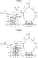
FIG. 5 is an explanatory diagram illustrating work of attaching the engine to the aircraft. -
FIG. 6 is an explanatory diagram illustrating work of attaching the engine to the aircraft. -
FIG. 7 is a partially cut-out side view illustrating a device for attaching an aircraft engine according to a second embodiment. -
FIG. 8 is a VII-VII cross-sectional view ofFIG. 6 illustrating the device for attaching the aircraft engine. -
FIG. 9 is a schematic diagram illustrating an operation state of the device for attaching the aircraft engine. -
FIG. 10 is a side view illustrating a device for attaching an aircraft engine according to a third embodiment. - The following describes preferred embodiments of the present disclosure in detail with reference to the drawings. The present disclosure is not limited to the embodiments, and in a case in which there are a plurality of embodiments, the embodiments may be combined with each other. Constituent elements in the embodiments include a constituent element that is easily conceivable by those skilled in the art, substantially the same constituent element, and what is called an equivalent.
-
FIG. 1 is a schematic diagram illustrating an attachment state of an engine with respect to an aircraft. - As illustrated in
FIG. 1 , anaircraft 100 includes a pair of left and rightmain planes 102 disposed on a front part of abody 101, a pair of left and righthorizontal tails 103 disposed on a rear part, and avertical tail 104. In theaircraft 100, for example, anaircraft engine 105 is attached to a lower part of each of themain planes 102. However, a mounting position of theaircraft engine 105 is not limited to the lower part of themain plane 102. Theaircraft engine 105 may be attached to thebody 101 in some cases. Anose landing gear 106 is disposed on the front part of theaircraft 100, and a pair of left and rightmain landing gears 107 are disposed on the rear part. - In the
aircraft 100, themain plane 102 is extended from a side part of thebody 101 along a horizontal direction. Note that themain plane 102 is extended from thebody 101 while being inclined toward an upper side in a vertical direction with a predetermined inclination angle with respect to the horizontal direction. Theaircraft engine 105 is attached to alower surface 102a of themain plane 102. Thus, thelower surface 102a of themain plane 102 to which theaircraft engine 105 is attached is extended in an inclination direction HD1 having an inclination angle α with respect to a horizontal direction HD. - The
aircraft engine 105 is conveyed to a lower side of an attachment position on thelower surface 102a of themain plane 102. Herein, theaircraft engine 105 is raised, and positioned at the attachment position on thelower surface 102a of themain plane 102. However, thelower surface 102a of themain plane 102 is inclined, so that it is difficult to position the engine at the attachment position on thelower surface 102a of themain plane 102 with high accuracy only by raising the engine toward an upper side in a vertical direction VD. That is, thelower surface 102a of themain plane 102 is extended along the inclination direction HD1 inclined by the inclination angle α with respect to the horizontal direction HD, so that theaircraft engine 105 needs to be obliquely raised along a movement direction VD1 orthogonal to the inclination direction HD1, that is, the movement direction VD1 that is inclined by an inclination angle β, which is equal to the inclination angle α, with respect to the vertical direction VD. Due to this, it is difficult to attach theaircraft engine 105 using a device that can raise the engine only in the vertical direction such as a crane or a lifter, which is typically used. -
FIG. 2 is a partially cut-out side view illustrating the device for attaching the aircraft engine according to a first embodiment,FIG. 3 is a III-III cross-sectional view ofFIG. 1 illustrating the device for attaching the aircraft engine, andFIG. 4 is a IV-IV cross-sectional view ofFIG. 1 illustrating the device for attaching the aircraft engine. - As illustrated in
FIG. 1 to FIG. 3 , adevice 10 for attaching the aircraft engine includes alinear movement device 11 and afirst swinging device 12. - The
aircraft engine 105 is supported by asupport frame 110. Thesupport frame 110 has a semi-cylindrical shape. That is, thesupport frame 110 includes abottom surface part 111 having a curved shape, and a pair ofend face parts end face part 112 is disposed on one side (left side inFIG. 2 ) of thebottom surface part 111, and theend face part 113 is disposed on the other side (right side inFIG. 2 ) of thesurface part 111. Thesupport frame 110 is disposed along the horizontal direction, and opens upward. Inside thesupport frame 110, theaircraft engine 105 is disposed along the horizontal direction. Theaircraft engine 105 is supported by thesupport frame 110 so that a rotation center axis O runs along the horizontal direction. - The
support frame 110 restrains theaircraft engine 105 with a plurality of (in the present embodiment, three)restraint members aircraft engine 105 is disposed inside thesupport frame 110, and anattachment part 105a is restrained by thesupport frame 110 with therestraint member 121. In theaircraft engine 105, oneend part 105b is restrained by thesupport frame 110 with therestraint member 122, and anotherend part 105c is restrained by thesupport frame 110 with therestraint member 123. - The
linear movement device 11 and thefirst swinging device 12 are mounted on a travelingcarrier 21. The travelingcarrier 21 has a plate shape along the horizontal direction. A plurality of (in the present embodiment, four) travelingwheels 22 are mounted on a lower surface part of the travelingcarrier 21. However, the number of the travelingwheels 22 is not limited to four. Each of the travelingwheels 22 can rotate about a center axis in the vertical direction with respect to the travelingcarrier 21, and can be steered toward a movement direction of the travelingcarrier 21. Although not illustrated, the travelingcarrier 21 includes a steering device that can steer each of the travelingwheels 22, and a drive device that can drive and rotate the traveling wheel. A driving operation of the travelingcarrier 21 can be performed when an operator rides thereon and operates a steering wheel, an accelerator pedal, and a brake pedal. However, the driving operation of the travelingcarrier 21 can be performed by remote control without the operator riding thereon. Alternatively, the travelingcarrier 21 may be configured to travel by being pulled by a vehicle. - The
linear movement device 11 is disposed on the travelingcarrier 21, and supports thesupport frame 110 to freely move along a movement direction orthogonal to the rotation center axis O. Thefirst swinging device 12 supports thesupport frame 110 to freely swing about a first center axis O1 parallel with the rotation center axis O. Specifically, thefirst swinging device 12 is disposed on the travelingcarrier 21, thefirst swinging device 12 supports thelinear movement device 11, and thelinear movement device 11 supports thesupport frame 110. - That is, a pair of
support members carrier 21 in a direction of the first center axis O1. Thesupport members support member 31 is fixed along a direction orthogonal to an axis direction of the first center axis O1 on one side in the axis direction of the first center axis O1 on the upper surface of the travelingcarrier 21. Thesupport member 32 is fixed along a direction orthogonal to the axis direction of the first center axis O1 on the other side in the axis direction of the first center axis O1 on the upper surface of the travelingcarrier 21. Thesupport member 31 and thesupport member 32 are opposed to each other in parallel with a gap longer than a length of thesupport frame 110 in the axis direction of the first center axis O1. - The
first swinging device 12 includes a pair of first swingingmembers first drive devices member 33 is disposed on thesupport member 32 side of thesupport member 31. Thefirst drive device 35 is disposed on a side opposite to thesupport member 32 of thesupport member 31. Thefirst drive device 35 is fixed to thesupport member 31, and anoutput shaft 35a positioned at the first center axis O1 passes through thesupport member 31 to be coupled to the first swingingmember 33. Thus, the first swingingmember 33 is supported by thesupport member 31 to freely swing (freely rotate) about the first center axis O1, and can be swung (rotated) by thefirst drive device 35. - The first swinging
member 34 is disposed on thesupport member 31 side of thesupport member 32. Thefirst drive device 36 is disposed on a side opposite to thesupport member 31 of thesupport member 32. Thefirst drive device 36 is fixed to thesupport member 32, and anoutput shaft 36a positioned at the first center axis O1 passes through thesupport member 32 to be coupled to the first swingingmember 34. Thus, the first swingingmember 34 is supported by thesupport member 32 to freely swing (freely rotate) about the first center axis O1, and can be swung (rotated) by thefirst drive device 36. - The pair of first swinging
members members members first swinging device 12, but only one of them may be disposed. - The
linear movement device 11 includesguide rails devices guide rail 41 includes a pair of parallel rail parts, and is fixed to an outer surface of theend face part 112 of thesupport frame 110. On the other hand, a guide recessed part (not illustrated) is disposed on a side surface on thesupport frame 110 side of the first swingingmember 33. Theguide rail 41 of thesupport frame 110 is fitted into the guide recessed part of the first swingingmember 33 to be able to linearly move. Thedrive device 43 is, for example, a pair of air cylinders (or hydraulic cylinders and the like), and fixed to both sides of the first swingingmember 33. A front end portion of adrive rod 43a of thedrive device 43 is coupled to acoupling part 112a fixed to theend face part 112 of thesupport frame 110. - The
guide rail 42 includes a pair of parallel rail parts, and is fixed to an outer surface of theend face part 113 of thesupport frame 110. On the other hand, a guide recessed part (not illustrated) is disposed on a side surface on thesupport frame 110 side of the first swingingmember 34. Theguide rail 42 of thesupport frame 110 is fitted into the guide recessed part of the first swingingmember 34 to be able to linearly move. Thedrive device 44 is, for example, a pair of air cylinders (or hydraulic cylinders and the like), and fixed to both sides of the first swingingmember 34. A front end portion of adrive rod 44a of thedrive device 44 is coupled to acoupling part 113a fixed to theend face part 113 of thesupport frame 110. - The guide rails 41 and 42 are disposed on the
support frame 110, and the guide recessed parts are disposed on the first swingingmembers support frame 110, and the guide rails 41 and 42 may be disposed on the first swingingmembers - In the
first swinging device 12, when thefirst drive devices output shafts members support frame 110, which is coupled to the first swingingmembers aircraft engine 105 supported by thesupport frame 110 can be swung, and a circumferential position (attachment angle) of theattachment part 105a on theaircraft engine 105 can be adjusted. - In the
linear movement device 11, when thedrive devices drive rods support frame 110 moves along the guide rails 41 and 42 via thecoupling parts support frame 110 is rotated by thefirst swinging device 12, and the guide rails 41 and 42 are inclined with respect to the vertical direction, thesupport frame 110 rises along a direction inclined with respect to the vertical direction. Thus, theaircraft engine 105 supported by thesupport frame 110 can be raised along the direction inclined with respect to the vertical direction. -
FIG. 5 and FIG. 6 are explanatory diagrams illustrating work of attaching the engine to the aircraft. - A method for attaching the engine according to the first embodiment includes a step of moving the
support frame 110 supporting theaircraft engine 105 along the horizontal direction to a lower side of an engine attachment position, a step of swinging thesupport frame 110 about the first center axis O1 parallel with the rotation center axis O of theaircraft engine 105 to move theaircraft engine 105 to have a predetermined inclination angle, and a step of moving thesupport frame 110 toward an upper side in the vertical direction along the inclination angle to be positioned at the engine attachment position. - As illustrated in
FIG. 1 , in theaircraft 100, theaircraft engine 105 is attached to thelower surface 102a of themain plane 102. Regular maintenance is required for theaircraft engine 105. When maintenance is performed on theaircraft engine 105, theaircraft 100 is conveyed to a maintenance site. Theaircraft engine 105 is then detached from themain plane 102, and attached to themain plane 102 again after the maintenance is performed. - As illustrated in
FIG. 5 , anattachment member 131 is fixed to thelower surface 102a of themain plane 102. Thelower surface 102a of themain plane 102 is inclined, so that theattachment member 131 fixed to thelower surface 102a is also inclined. Accordingly, theaircraft engine 105 to be attached to theattachment member 131 needs to be obliquely raised along the movement direction VD1 that is inclined by the inclination angle β with respect to the vertical direction VD. Thus, at the time of attaching theaircraft engine 105 to themain plane 102 with theattachment member 131, theaircraft engine 105 needs to be inclined corresponding to the inclination angle of theattachment member 131 and raised toward the upper side in the vertical direction to be positioned at the attachment position. - As illustrated in
FIG. 2 , theaircraft engine 105 is supported by thesupport frame 110, and thesupport frame 110 is supported by thedevice 10 for attaching the aircraft engine. First, as illustrated inFIG. 5 , the travelingcarrier 21 is moved, and theaircraft engine 105 supported by thesupport frame 110 is moved to the lower side of the attachment position, that is, the lower side of theattachment member 131 fixed to themain plane 102, and stopped. - As illustrated in
FIG. 6 , by operating the first swinging device 12 (refer toFIG. 2 ), thesupport frame 110 is swung by the inclination angle β about the first center axis O1. In theaircraft engine 105 supported by thesupport frame 110, a rising direction of theattachment part 105a matches a fitting direction with respect to theattachment member 131 at a position where theattachment part 105a is opposed to theattachment member 131. In this state, by operating the linear movement device 11 (refer toFIG. 2 ), thesupport frame 110 is raised toward the upper side in the movement direction VD1 that is inclined by the inclination angle β with respect to the vertical direction VD while maintaining the inclination angle β of thesupport frame 110. Accordingly, in theaircraft engine 105 supported by thesupport frame 110, theattachment part 105a is properly fitted into theattachment member 131 of themain plane 102, and positioned at a proper position. - Subsequently, the
attachment part 105a of theaircraft engine 105 is fastened to theattachment member 131, and support for theaircraft engine 105 by thesupport frame 110 is released. For theaircraft engine 105, a nacelle or the like enclosing theaircraft engine 105 is disposed on the lower part of themain plane 102, but is not illustrated herein. - Herein, described is work of attaching the
aircraft engine 105 to themain plane 102 by thedevice 10 for attaching the aircraft engine according to the present embodiment, but thedevice 10 for attaching the aircraft engine can be applied to work of detaching theaircraft engine 105 from themain plane 102. -
FIG. 7 is a partially cut-out side view illustrating the device for attaching the aircraft engine according to a second embodiment,FIG. 8 is a VII-VII cross-sectional view ofFIG. 6 illustrating the device for attaching the aircraft engine, andFIG. 9 is a schematic diagram illustrating an operation state of the device for attaching the aircraft engine. A member having the same function as that in the first embodiment described above is denoted by the same reference numeral, and detailed description thereof will not be repeated. - As illustrated in
FIG. 7 andFIG. 8 , adevice 10A for attaching the aircraft engine includes thelinear movement device 11, thefirst swinging device 12, and asecond swinging device 13. Thelinear movement device 11 and thefirst swinging device 12 are substantially the same as those in the first embodiment. - The
second swinging device 13 is disposed on the travelingcarrier 21, and supports thesupport frame 110 to freely swing about a second center axis O2 that is orthogonal to the first center axis O1 and runs along the horizontal direction. Specifically, thesecond swinging device 13 is disposed on the travelingcarrier 21, thesecond swinging device 13 supports thefirst swinging device 12, thefirst swinging device 12 supports thelinear movement device 11, and thelinear movement device 11 supports thesupport frame 110. Positions of the first center axis O1 and the second center axis O2 in the vertical direction may be the same, or may be shifted from each other. - That is, the pair of
support members carrier 21 in a direction of the second center axis O2. Thesupport members support member 31 is fixed along a direction orthogonal to an axis direction of the second center axis O2 on an upper surface of the travelingcarrier 21 on one side in the axis direction of the second center axis O2. Thesupport member 32 is fixed along a direction orthogonal to the axis direction of the second center axis O2 on an upper surface of the travelingcarrier 21 on the other side in the axis direction of the second center axis O2. Thesupport member 31 and thesupport member 32 are opposed to each other in parallel with a gap longer than a length of thesupport frame 110 in the axis direction of the second center axis O2. - The
second swinging device 13 includes a second swingingmember 51, and a pair ofsecond drive devices member 51 has a rectangular frame shape, and is disposed along the vertical direction between thesupport member 31 and thesupport member 32. The second swingingmember 51 includesfirst members support member 31 and thesupport member 32, andsecond members first members second drive device 52 is disposed on a side opposite to thesupport member 32 of thesupport member 31. Thesecond drive device 53 is disposed on a side opposite to thesupport member 31 of thesupport member 32. Thesecond drive device 52 is fixed to thesupport member 31, and an output shaft 52a positioned at the second center axis O2 passes through thesupport member 31 to be coupled to thefirst member 51a of the second swingingmember 51. Thesecond drive device 53 is fixed to thesupport member 32, and an output shaft 53a positioned at the second center axis O2 passes through thesupport member 32 to be coupled to thefirst member 51b of the second swingingmember 51. - Thus, the second swinging
member 51 is supported by thesupport members second drive devices second drive devices second swinging device 13, but only one of them may be disposed. - The
first swinging device 12 includes the pair of first swingingmembers first drive devices member 33 is disposed on thefirst member 51b side of thefirst member 51a of the second swingingmember 51. Thefirst drive device 35 is disposed on a side opposite to thefirst member 51b of thefirst member 51a. Thefirst drive device 35 is fixed to thefirst member 51a, and theoutput shaft 35a positioned at the first center axis O1 passes through thefirst member 51a to be coupled to the first swingingmember 33. Thus, the first swingingmember 33 is supported by thefirst member 51a to freely swing (freely rotate) about the first center axis O1, and can be swung (rotated) by thefirst drive device 35. - The first swinging
member 34 is disposed on thefirst member 51a side of thefirst member 51b of the second swingingmember 51. Thefirst drive device 36 is disposed on a side opposite to thefirst member 51a of thefirst member 51b. Thefirst drive device 36 is fixed to thefirst member 51b, and theoutput shaft 36a positioned at the first center axis O1 passes through thefirst member 51b to be coupled to the first swingingmember 34. Thus, the first swingingmember 34 is supported by thefirst member 51b to freely swing (freely rotate) about the first center axis O1, and can be swung (rotated) by thefirst drive device 36. - The
linear movement device 11 includes the guide rails 41 and 42, and thedrive devices - In the
second swinging device 13, when thesecond drive devices member 51 rotates about the second center axis O2. Accordingly, thesupport frame 110, which is supported by the second swingingmember 51 via thefirst swinging device 12 and thelinear movement device 11, rotates about the second center axis O2. Thus, theaircraft engine 105 supported by thesupport frame 110 can be swung, and an angle of theattachment part 105a of theaircraft engine 105 with respect to the axis direction (direction of a rotation center axis) can be adjusted. - As illustrated in
FIG. 9 , in theaircraft 100, thelower surface 102a of themain plane 102 may be inclined, in a front and rear direction, toward the upper side in the vertical direction with a predetermined inclination angle with respect to the horizontal direction. Thus, at the time of attaching theaircraft engine 105 to themain plane 102, theaircraft engine 105 needs to be inclined with respect to the horizontal direction (vertical direction) in the front and rear of a direction of the rotation center axis O (first center axis O1). - That is, the
aircraft engine 105 is supported by thesupport frame 110, and thesupport frame 110 is supported by thedevice 10A for attaching the aircraft engine. First, the travelingcarrier 21 is moved, and theaircraft engine 105 supported by thesupport frame 110 is moved to the lower side of the attachment position, that is, the lower side of theattachment member 131 fixed to themain plane 102, and stopped. - By operating the second swinging device 13 (refer to
FIG. 8 ), thesupport frame 110 is swung by a predetermined inclination angle about the second center axis O2. In theaircraft engine 105 supported by thesupport frame 110, a rising direction of theattachment part 105a matches a fitting direction with respect to theattachment member 131 at a position where theattachment part 105a is opposed to theattachment member 131. In this state, by operating the linear movement device 11 (refer toFIG. 7 ), thesupport frame 110 is raised while maintaining the inclination angle of thesupport frame 110. Accordingly, in theaircraft engine 105 supported by thesupport frame 110, theattachment part 105a is properly fitted into theattachment member 131 of themain plane 102, and positioned at a proper position. - Subsequently, the
attachment part 105a of theaircraft engine 105 is fastened to theattachment member 131, and support for theaircraft engine 105 by thesupport frame 110 is released. Herein, described is work of attaching theaircraft engine 105 to themain plane 102 by thedevice 10A for attaching the aircraft engine according to the present embodiment, but thedevice 10A for attaching the aircraft engine can be applied to work of detaching theaircraft engine 105 from themain plane 102. -
FIG. 10 is a side view illustrating the device for attaching the aircraft engine according to a third embodiment. A member having the same function as that in the first embodiment described above is denoted by the same reference numeral, and detailed description thereof will not be repeated. - As illustrated in
FIG. 10 , adevice 10B for attaching the aircraft engine includes thelinear movement device 11, thefirst swinging device 12, and asecond swinging device 13A. Thelinear movement device 11 and thefirst swinging device 12 are substantially the same as those in the first embodiment. - The
second swinging device 13A is disposed on the travelingcarrier 21, and supports thesupport frame 110 to freely swing about the second center axis O2 that is orthogonal to the first center axis O1 and runs along the horizontal direction. Specifically, the four travelingwheels 22 are mounted on the lower surface part of the travelingcarrier 21. The two travelingwheels 22 on one side (left side inFIG. 10 ) of the first center axis O1 are mounted on the lower surface of the travelingcarrier 21 via ahydraulic cylinder 61 constituting thesecond swinging device 13A. Thesecond swinging device 13A supports thesupport frame 110 to freely swing by performing extension driving (or contraction driving) for thehydraulic cylinder 61 to incline the travelingcarrier 21. In this case, the second center axis O2 becomes a grounding position of the travelingwheel 22 on the other side (right side inFIG. 10 ) of the first center axis O1. The two travelingwheels 22 on the other side (right side inFIG. 10 ) of the first center axis O1 may also be mounted on the lower surface of the travelingcarrier 21 via a hydraulic cylinder constituting thesecond swinging device 13A. - Behavior of the
device 10B for attaching the aircraft engine is the same as that of thedevice 10A for attaching the aircraft engine in the second embodiment, so that description thereof will not be repeated. - The device for attaching the aircraft engine according to a first aspect includes the
linear movement device 11 that supports thesupport frame 110 supporting theaircraft engine 105 along the horizontal direction to freely move in the movement direction orthogonal to the rotation center axis O of theaircraft engine 105, and thefirst swinging device 12 that supports thesupport frame 110 to freely swing about the first center axis O1 parallel with the rotation center axis O. - With the device for attaching the aircraft engine according to the first aspect, the attachment angle of the
aircraft engine 105 can be adjusted by thefirst swinging device 12 by swinging thesupport frame 110 supporting theaircraft engine 105 even if the attachment angle of theaircraft engine 105 with respect to theaircraft 100 is inclined in a right and left direction with respect to the vertical direction, and workability in work of attaching/detaching the aircraft engine can be improved. - The device for attaching the aircraft engine according to a second aspect is the device for attaching the aircraft engine according to the first aspect further including the traveling
carrier 21. Additionally, thefirst swinging device 12 is disposed on the travelingcarrier 21, thefirst swinging device 12 supports thelinear movement device 11, and thelinear movement device 11 supports thesupport frame 110. Due to this, by causing the travelingcarrier 21 to travel, thelinear movement device 11, thefirst swinging device 12, and thesupport frame 110 can be moved to desired positions. - The device for attaching the aircraft engine according to a third aspect is the device for attaching the aircraft engine according to the second aspect, and additionally, the pair of
support members carrier 21, the pair of first swingingmembers first swinging device 12 are supported by the pair ofsupport members linear movement device 11 supports thesupport frame 110 to freely move with respect to the pair of first swingingmembers linear movement device 11 and thefirst swinging device 12 can be efficiently mounted on the travelingcarrier 21. - The device for attaching the aircraft engine according to a fourth aspect is the device for attaching the aircraft engine according to the second aspect or the third aspect, and additionally, the traveling
carrier 21 includes at least three travelingwheels 22 that can be steered. Due to this, the position of theaircraft engine 105 with respect to the engine attachment position can be easily adjusted. - The device for attaching the aircraft engine according to a fifth aspect is the device for attaching the aircraft engine according to any one of the first aspect to the fourth aspect, and further includes the
second swinging devices support frame 110 to freely swing about the second center axis O2 that is orthogonal to the first center axis O1 and runs along the horizontal direction. Due to this, the attachment angle of theaircraft engine 105 can be adjusted by thefirst swinging device 12 and thesecond swinging devices support frame 110 supporting theaircraft engine 105 even if the attachment angle of theaircraft engine 105 with respect to theaircraft 100 is inclined in the front and rear direction and the right and left direction with respect to the vertical direction. - The device for attaching the aircraft engine according to a sixth aspect is the device for attaching the aircraft engine according to the fifth aspect further including the traveling
carrier 21. Additionally, thesecond swinging device 13 is disposed on the travelingcarrier 21, thesecond swinging device 13 supports thefirst swinging device 12, thefirst swinging device 12 supports thelinear movement device 11, and thelinear movement device 11 supports thesupport frame 110. Due to this, by causing the travelingcarrier 21 to travel, thelinear movement device 11, thefirst swinging device 12, thesecond swinging device 13, and thesupport frame 110 can be moved to desired positions. - The device for attaching the aircraft engine according to a seventh aspect is the device for attaching the aircraft engine according to the fifth aspect or the sixth aspect, and additionally, the pair of
support members carrier 21, the second swingingmember 51 constituting thesecond swinging device 13 is supported by the pair ofsupport members members first swinging device 12 are supported by the second swingingmember 51 to freely swing, and thelinear movement device 11 supports thesupport frame 110 to freely move with respect to the pair of first swingingmembers linear movement device 11, thefirst swinging device 12, and thesecond swinging device 13 can be efficiently mounted on the travelingcarrier 21. - The device for attaching the aircraft engine according to an eighth aspect is the device for attaching the aircraft engine according to the seventh aspect, and additionally, the
second swinging device 13A supports thesupport frame 110 to freely swing by inclining the travelingcarrier 21. Due to this, the structure can be simplified without modifying thelinear movement device 11 or thefirst swinging device 12. - The method for attaching the aircraft engine according to a ninth aspect includes a step of moving the
support frame 110 supporting theaircraft engine 105 along the horizontal direction to a lower side of an engine attachment position, a step of swinging thesupport frame 110 about the first center axis O1 parallel with the rotation center axis O of theaircraft engine 105 to move theaircraft engine 105 to have a predetermined inclination angle, and a step of moving thesupport frame 110 toward an upper side in the vertical direction along the inclination angle to be positioned at the engine attachment position. Due to this, the attachment angle of theaircraft engine 105 can be adjusted even if the attachment angle of theaircraft engine 105 with respect to theaircraft 100 is inclined with respect to the vertical direction, and workability in work of attaching/detaching the aircraft engine can be improved. - In the embodiment described above, the
support frame 110 is assumed to have a semi-cylindrical shape, but the shape is not limited thereto. The shape may be any shape so long as it supports theaircraft engine 105. - In the embodiment described above, the second swinging device is assumed to be the
hydraulic cylinder 61, but the first swinging device may be a fluid pressure cylinder such as thehydraulic cylinder 61. Each of the first swinging device and the second swinging device is not limited to the fluid pressure cylinder, but may be a screw device and the like. -
- 10, 10A, 10B DEVICE FOR ATTACHING AIRCRAFT ENGINE
- 11 LINEAR MOVEMENT DEVICE
- 12 FIRST SWINGING DEVICE
- 13, 13A SECOND SWINGING DEVICE
- 21 TRAVELING CARRIER
- 22 TRAVELING WHEEL
- 31, 32 SUPPORT MEMBER
- 33, 34 FIRST SWINGING MEMBER
- 35, 36 FIRST DRIVE DEVICE
- 41, 42 GUIDE RAIL
- 43, 44 DRIVE DEVICE
- 51 SECOND SWINGING MEMBER
- 52, 53 SECOND DRIVE DEVICE
- 61 HYDRAULIC CYLINDER
- 100 AIRCRAFT
- 101 BODY
- 102 MAIN PLANE
- 103 HORIZONTAL TAIL
- 104 VERTICAL TAIL
- 105 AIRCRAFT ENGINE
- 110 SUPPORT FRAME
Claims (9)
- A device for attaching an aircraft engine, the device comprising:a linear movement device configured to support a support frame for supporting an aircraft engine along a horizontal direction to freely move along a movement direction orthogonal to a rotation center axis of the aircraft engine; anda first swinging device configured to support the support frame to freely swing about a first center axis parallel with the rotation center axis.
- The device for attaching the aircraft engine according to claim 1, the device further comprising:a traveling carrier, whereinthe first swinging device is disposed on the traveling carrier, the first swinging device supports the linear movement device, and the linear movement device supports the support frame.
- The device for attaching the aircraft engine according to claim 2, wherein a pair of support members are disposed on one side and another side in a direction of the first center axis of the traveling carrier, a pair of first swinging members constituting the first swinging device are supported by the pair of support members to freely swing, and the linear movement device supports the support frame to freely move with respect to the pair of first swinging members.
- The device for attaching the aircraft engine according to claim 2 or 3, wherein the traveling carrier includes at least three wheels that is able to be steered.
- The device for attaching the aircraft engine according to claim 1, the device further comprising:
a second swinging device configured to support the support frame to freely swing about a second center axis that is orthogonal to the first center axis and runs along the horizontal direction. - The device for attaching the aircraft engine according to claim 5, the device further comprising:a traveling carrier, whereinthe second swinging device is disposed on the traveling carrier, the second swinging device supports the first swinging device, the first swinging device supports the linear movement device, and the linear movement device supports the support frame.
- The device for attaching the aircraft engine according to claim 6, wherein a pair of support members are disposed on one side and another side in a direction of the second center axis of the traveling carrier, a second swinging member constituting the second swinging device is supported by the pair of support members to freely swing, a pair of first swinging members constituting the first swinging device are supported by the second swinging member to freely swing, and the linear movement device supports the support frame to freely move with respect to the pair of first swinging members.
- The device for attaching the aircraft engine according to claim 6 or 7, wherein the second swinging device supports the support frame to freely swing by inclining the traveling carrier.
- A method for attaching an aircraft engine, the method comprising the steps of:moving a support frame for supporting the aircraft engine along a horizontal direction to a lower side of an engine attachment position;swinging the support frame about a first center axis parallel with a rotation center axis of the aircraft engine to move the aircraft engine to have a predetermined inclination angle; andmoving the support frame toward an upper side in a vertical direction along the inclination angle to be positioned at the engine attachment position.
Applications Claiming Priority (2)
| Application Number | Priority Date | Filing Date | Title |
|---|---|---|---|
| JP2022130079A JP2024027348A (en) | 2022-08-17 | 2022-08-17 | Aircraft engine mounting device and method |
| PCT/JP2023/024869 WO2024038696A1 (en) | 2022-08-17 | 2023-07-05 | Device and method for attaching aircraft engine |
Publications (2)
| Publication Number | Publication Date |
|---|---|
| EP4552981A1 true EP4552981A1 (en) | 2025-05-14 |
| EP4552981A4 EP4552981A4 (en) | 2025-10-01 |
Family
ID=89941424
Family Applications (1)
| Application Number | Title | Priority Date | Filing Date |
|---|---|---|---|
| EP23854733.5A Pending EP4552981A4 (en) | 2022-08-17 | 2023-07-05 | DEVICE AND METHOD FOR MOUNTING AN AIRCRAFT ENGINE |
Country Status (5)
| Country | Link |
|---|---|
| US (1) | US20260035104A1 (en) |
| EP (1) | EP4552981A4 (en) |
| JP (1) | JP2024027348A (en) |
| CN (1) | CN119630587A (en) |
| WO (1) | WO2024038696A1 (en) |
Family Cites Families (6)
| Publication number | Priority date | Publication date | Assignee | Title |
|---|---|---|---|---|
| FR2449057A1 (en) * | 1979-02-19 | 1980-09-12 | Sovam | Trolley with scissor lift - is used to position load and pivotal about horizontal and vertical axes |
| DE19612626A1 (en) * | 1996-03-29 | 1997-10-02 | Hydro Geraetebau Gmbh & Co Kg | Appliance for positioning and transporting aeroplane power plants |
| US6546616B2 (en) * | 2000-12-15 | 2003-04-15 | Bell Helicopter Textron Inc. | Six-axis alignment and installation tool |
| US20120110816A1 (en) * | 2010-11-08 | 2012-05-10 | The Boeing Company | Engine Loading System |
| JP6450076B2 (en) | 2014-02-24 | 2019-01-09 | 三菱航空機株式会社 | Aircraft, aircraft engine pylon, and method of attaching engine to aircraft body |
| US11560298B2 (en) * | 2021-01-05 | 2023-01-24 | The Boeing Company | Engine installation systems and related methods |
-
2022
- 2022-08-17 JP JP2022130079A patent/JP2024027348A/en active Pending
-
2023
- 2023-07-05 US US19/103,390 patent/US20260035104A1/en active Pending
- 2023-07-05 WO PCT/JP2023/024869 patent/WO2024038696A1/en not_active Ceased
- 2023-07-05 EP EP23854733.5A patent/EP4552981A4/en active Pending
- 2023-07-05 CN CN202380059911.9A patent/CN119630587A/en active Pending
Also Published As
| Publication number | Publication date |
|---|---|
| WO2024038696A1 (en) | 2024-02-22 |
| JP2024027348A (en) | 2024-03-01 |
| US20260035104A1 (en) | 2026-02-05 |
| EP4552981A4 (en) | 2025-10-01 |
| CN119630587A (en) | 2025-03-14 |
Similar Documents
| Publication | Publication Date | Title |
|---|---|---|
| JP5951469B2 (en) | Chassis assembly equipment for automobile assembly line | |
| US20080179167A1 (en) | Hanger system | |
| CN105966549B (en) | A kind of screw shaft of ship mounting device | |
| CN202768014U (en) | Lining trolley for emergency parking strip | |
| CN109162205B (en) | Arch rib folding section mounting structure and mounting method | |
| CN208648629U (en) | A kind of liftable suspender | |
| CN101967988A (en) | Quickly-installed manipulator of attached type tunnel arch | |
| CN107443348A (en) | Lift various dimensions adjust motor mounts car | |
| US20260035104A1 (en) | Device and method for attaching aircraft engine | |
| CN102745337A (en) | Large aircraft trailing edge flap mandrel assembly vehicle and its installation method | |
| CN118207806A (en) | Structure is assembled to high altitude steel construction vestibule | |
| EP2789487B1 (en) | Engine supporting structure for working vehicle | |
| CN210413397U (en) | Assembly system of variable pitch speed reducer of wind generating set | |
| CN103303483A (en) | Rotating mechanism for mounting and maintaining aero-engine | |
| CN208233167U (en) | A kind of new-energy automobile Universal, modular sole | |
| CN217872791U (en) | Up-down passing structure for assembling large-diameter tunnel arc-shaped parts | |
| CN111422248A (en) | Subway rail laying vehicle with automatic control automobile body levelness function | |
| CN215658880U (en) | A car chassis tightening device | |
| CN201851133U (en) | Attached type quick mounting manipulator for tunnel arches | |
| CN104315249A (en) | Industrial pipeline mounting method | |
| CN104401409B (en) | lifting cab and tunnel boring machine | |
| CN103128700A (en) | Automobile main reducer assembly separated-installed machine | |
| CN206229935U (en) | A kind of Novel steel forming mill | |
| CN223701249U (en) | A tension release machine suitable for use in the production of precast concrete piles/poles | |
| CN115355024B (en) | An integrated transport and safety machine for lining transportation and installation |
Legal Events
| Date | Code | Title | Description |
|---|---|---|---|
| STAA | Information on the status of an ep patent application or granted ep patent |
Free format text: STATUS: THE INTERNATIONAL PUBLICATION HAS BEEN MADE |
|
| PUAI | Public reference made under article 153(3) epc to a published international application that has entered the european phase |
Free format text: ORIGINAL CODE: 0009012 |
|
| STAA | Information on the status of an ep patent application or granted ep patent |
Free format text: STATUS: REQUEST FOR EXAMINATION WAS MADE |
|
| 17P | Request for examination filed |
Effective date: 20250207 |
|
| AK | Designated contracting states |
Kind code of ref document: A1 Designated state(s): AL AT BE BG CH CY CZ DE DK EE ES FI FR GB GR HR HU IE IS IT LI LT LU LV MC ME MK MT NL NO PL PT RO RS SE SI SK SM TR |
|
| A4 | Supplementary search report drawn up and despatched |
Effective date: 20250903 |
|
| RIC1 | Information provided on ipc code assigned before grant |
Ipc: B64F 5/10 20170101AFI20250828BHEP Ipc: B64F 5/50 20170101ALI20250828BHEP Ipc: B62B 3/00 20060101ALI20250828BHEP Ipc: B62B 3/10 20060101ALI20250828BHEP Ipc: B62B 5/00 20060101ALI20250828BHEP |
|
| DAV | Request for validation of the european patent (deleted) | ||
| DAX | Request for extension of the european patent (deleted) |