EP4552877A1 - Vehicle - Google Patents
Vehicle Download PDFInfo
- Publication number
- EP4552877A1 EP4552877A1 EP23833571.5A EP23833571A EP4552877A1 EP 4552877 A1 EP4552877 A1 EP 4552877A1 EP 23833571 A EP23833571 A EP 23833571A EP 4552877 A1 EP4552877 A1 EP 4552877A1
- Authority
- EP
- European Patent Office
- Prior art keywords
- axle
- unit
- vehicle
- electric wire
- wire harness
- Prior art date
- Legal status (The legal status is an assumption and is not a legal conclusion. Google has not performed a legal analysis and makes no representation as to the accuracy of the status listed.)
- Granted
Links
Images



Classifications
-
- B—PERFORMING OPERATIONS; TRANSPORTING
- B60—VEHICLES IN GENERAL
- B60R—VEHICLES, VEHICLE FITTINGS, OR VEHICLE PARTS, NOT OTHERWISE PROVIDED FOR
- B60R16/00—Electric or fluid circuits specially adapted for vehicles and not otherwise provided for; Arrangement of elements of electric or fluid circuits specially adapted for vehicles and not otherwise provided for
- B60R16/02—Electric or fluid circuits specially adapted for vehicles and not otherwise provided for; Arrangement of elements of electric or fluid circuits specially adapted for vehicles and not otherwise provided for electric constitutive elements
- B60R16/0207—Wire harnesses
- B60R16/0215—Protecting, fastening and routing means therefor
-
- B—PERFORMING OPERATIONS; TRANSPORTING
- B60—VEHICLES IN GENERAL
- B60R—VEHICLES, VEHICLE FITTINGS, OR VEHICLE PARTS, NOT OTHERWISE PROVIDED FOR
- B60R16/00—Electric or fluid circuits specially adapted for vehicles and not otherwise provided for; Arrangement of elements of electric or fluid circuits specially adapted for vehicles and not otherwise provided for
- B60R16/02—Electric or fluid circuits specially adapted for vehicles and not otherwise provided for; Arrangement of elements of electric or fluid circuits specially adapted for vehicles and not otherwise provided for electric constitutive elements
- B60R16/03—Electric or fluid circuits specially adapted for vehicles and not otherwise provided for; Arrangement of elements of electric or fluid circuits specially adapted for vehicles and not otherwise provided for electric constitutive elements for supply of electrical power to vehicle subsystems or for
-
- B—PERFORMING OPERATIONS; TRANSPORTING
- B60—VEHICLES IN GENERAL
- B60K—ARRANGEMENT OR MOUNTING OF PROPULSION UNITS OR OF TRANSMISSIONS IN VEHICLES; ARRANGEMENT OR MOUNTING OF PLURAL DIVERSE PRIME-MOVERS IN VEHICLES; AUXILIARY DRIVES FOR VEHICLES; INSTRUMENTATION OR DASHBOARDS FOR VEHICLES; ARRANGEMENTS IN CONNECTION WITH COOLING, AIR INTAKE, GAS EXHAUST OR FUEL SUPPLY OF PROPULSION UNITS IN VEHICLES
- B60K1/00—Arrangement or mounting of electrical propulsion units
-
- B—PERFORMING OPERATIONS; TRANSPORTING
- B60—VEHICLES IN GENERAL
- B60R—VEHICLES, VEHICLE FITTINGS, OR VEHICLE PARTS, NOT OTHERWISE PROVIDED FOR
- B60R16/00—Electric or fluid circuits specially adapted for vehicles and not otherwise provided for; Arrangement of elements of electric or fluid circuits specially adapted for vehicles and not otherwise provided for
- B60R16/02—Electric or fluid circuits specially adapted for vehicles and not otherwise provided for; Arrangement of elements of electric or fluid circuits specially adapted for vehicles and not otherwise provided for electric constitutive elements
- B60R16/023—Electric or fluid circuits specially adapted for vehicles and not otherwise provided for; Arrangement of elements of electric or fluid circuits specially adapted for vehicles and not otherwise provided for electric constitutive elements for transmission of signals between vehicle parts or subsystems
- B60R16/027—Electric or fluid circuits specially adapted for vehicles and not otherwise provided for; Arrangement of elements of electric or fluid circuits specially adapted for vehicles and not otherwise provided for electric constitutive elements for transmission of signals between vehicle parts or subsystems between relatively movable parts of the vehicle, e.g. between steering wheel and column
-
- H—ELECTRICITY
- H02—GENERATION; CONVERSION OR DISTRIBUTION OF ELECTRIC POWER
- H02K—DYNAMO-ELECTRIC MACHINES
- H02K11/00—Structural association of dynamo-electric machines with electric components or with devices for shielding, monitoring or protection
- H02K11/30—Structural association with control circuits or drive circuits
- H02K11/33—Drive circuits, e.g. power electronics
-
- H—ELECTRICITY
- H02—GENERATION; CONVERSION OR DISTRIBUTION OF ELECTRIC POWER
- H02K—DYNAMO-ELECTRIC MACHINES
- H02K5/00—Casings; Enclosures; Supports
- H02K5/04—Casings or enclosures characterised by the shape, form or construction thereof
- H02K5/22—Auxiliary parts of casings not covered by groups H02K5/06-H02K5/20, e.g. shaped to form connection boxes or terminal boxes
- H02K5/225—Terminal boxes or connection arrangements
-
- B—PERFORMING OPERATIONS; TRANSPORTING
- B60—VEHICLES IN GENERAL
- B60K—ARRANGEMENT OR MOUNTING OF PROPULSION UNITS OR OF TRANSMISSIONS IN VEHICLES; ARRANGEMENT OR MOUNTING OF PLURAL DIVERSE PRIME-MOVERS IN VEHICLES; AUXILIARY DRIVES FOR VEHICLES; INSTRUMENTATION OR DASHBOARDS FOR VEHICLES; ARRANGEMENTS IN CONNECTION WITH COOLING, AIR INTAKE, GAS EXHAUST OR FUEL SUPPLY OF PROPULSION UNITS IN VEHICLES
- B60K1/00—Arrangement or mounting of electrical propulsion units
- B60K2001/001—Arrangement or mounting of electrical propulsion units one motor mounted on a propulsion axle for rotating right and left wheels of this axle
-
- B—PERFORMING OPERATIONS; TRANSPORTING
- B60—VEHICLES IN GENERAL
- B60Y—INDEXING SCHEME RELATING TO ASPECTS CROSS-CUTTING VEHICLE TECHNOLOGY
- B60Y2200/00—Type of vehicle
- B60Y2200/10—Road Vehicles
- B60Y2200/14—Trucks; Load vehicles, Busses
Definitions
- the present invention relates to a vehicle.
- Patent Document 1 discloses a vehicle in which a vehicle body-side device and a vehicle wheel-side device are connected by a wire harness.
- Patent Document 1 WO2021/ 166138
- the present invention has been made in view of such a technical problem, and an object thereof is to improve the durability of an electric wire that connects units mounted on a vehicle.
- a vehicle includes a first unit on which a rotary electric machine is mounted, a second unit on which an inverter is mounted, an electric wire that electrically connects the first unit and the second unit, and a vehicle wheel that is dynamically connected downstream of the first unit via an axle, in which the electric wire has a portion routed along the axle.
- an object is to improve the durability of the electric wire that connects the units mounted on the vehicle.
- a vehicle V according to the present embodiment is an electric vehicle using a motor as a drive source. As shown in FIGS. 1 to 4 , the vehicle V includes a frame 1, an axle 2, vehicle wheels 3, a plurality of leaf springs 4, an electric unit 5 as a first unit, and a control unit 6 as a second unit.
- the frame 1 includes a pair of side members 1a extending in a front-rear direction of the vehicle V at an interval, and a plurality of cross members 1b each extending in a width direction of the vehicle V and each having both ends respectively connected to the pair of side members 1a.
- Each side member 1a and each cross member 1b are made of, for example, a steel material or an aluminum material.
- the axle 2 includes a right axle 2a and a left axle 2b.
- the vehicle wheels 3 are attached to end portions of the right axle 2a and the left axle 2b, respectively.
- the axle 2 dynamically connects the electric unit 5 and the vehicle wheels 3 located downstream of a power transmission path.
- the axle 2 is suspended from the frame 1 via the plurality of stacked leaf springs 4. That is, the vehicle V has a rigid axle type suspension structure. Further, the axle 2 is connected to the cross members 1b via torque rods 7 as rods extending in a direction intersecting the axle 2. Both ends of each torque rod 7 are swingably supported by brackets respectively attached to the axle 2 and the cross member 1b.
- the electric unit 5 is attached onto the axle 2.
- the electric unit 5 includes, in a case, a rotary electric machine M and a differential gear (not shown) that distributes an output of the rotary electric machine M to the right axle 2a and the left axle 2b.
- the rotary electric machine M functions as the drive source of the vehicle V.
- the rotary electric machine M is implemented by, for example, a three-phase AC permanent magnet synchronous motor.
- the rotary electric machine M is driven by electric power supplied from a battery (not shown) provided in a vehicle body via the control unit 6. Rotational power generated by the rotary electric machine M is transmitted to the vehicle wheels 3 via the differential gear (not shown), the right axle 2a, and the left axle 2b.
- the electric unit 5 has a regeneration function of receiving the rotational power from the vehicle wheels 3 and generating electric power for charging the battery during deceleration or braking of the vehicle V.
- An inverter device 6a having an inverter circuit and a converter circuit is mounted in the control unit 6.
- the control unit 6 is attached to a lower portion of the vehicle body, for example, in the vicinity of the cross member 1b.
- the electric unit 5 and the control unit 6 are electrically connected by a wire harness 8 (electric wire).
- the vehicle V since the vehicle V has the rigid axle type suspension structure, for example, when the vehicle V travels on a rough road or the like, the axle 2 vigorously swings. At this time, since the electric unit 5 is attached onto the axle 2, the electric unit 5 also vigorously swings. When the electric unit 5 vigorously swings, the wire harness 8, which connects the control unit 6 provided in the vehicle body and the electric unit 5 attached onto the axle 2, vigorously swings, and the durability of the wire harness 8 and connector portions of the wire harness 8 may decrease.
- FIG. 4 is an enlarged view of a portion in which the wire harness 8 is routed shown in FIG. 2 .
- the wire harness 8 includes a first wiring portion 8a routed along the right axle 2a, a second wiring portion 8c routed along the torque rod 7, a third wiring portion 8e routed along the cross member 1b, a first bent portion 8b connecting the first wiring portion 8a and the second wiring portion 8c, and a second bent portion 8d connecting the second wiring portion 8c and the third wiring portion 8e.
- connection portion 9 The first wiring portion 8a and the first bent portion 8b are electrically connected by one connection portion 9 attached to the right axle 2a.
- the first bent portion 8b and the second wiring portion 8c, and the second wiring portion 8c and the second bent portion 8d are electrically connected by connection portions 9 attached to the torque rod 7.
- the second bent portion 8d and the third wiring portion 8e are electrically connected by one connection portion 9 attached to the cross member 1b.
- Each connection portion 9 is a member that electrically connects adjacent wires to each other, and is implemented by a connector, a terminal block, or the like.
- the first bent portion 8b is a portion that absorbs a tensile force or a compression force acting on the connection portions with the first wiring portion 8a and the second wiring portion 8c when the axle 2 and the torque rod 7 are relatively displaced.
- the first bent portion 8b is formed by bending the electric wire.
- the first bent portion 8b is formed to bend the electric wire in a direction away from the vehicle wheel 3.
- the second bent portion 8d is a portion that absorbs a tensile force or a compression force acting on the connection portions with the second wiring portion 8c and the third wiring portion 8e when the torque rod 7 and the frame 1 (cross member 1b) are relatively displaced.
- the second bent portion 8d is formed by bending the electric wire.
- the second bent portion 8d is formed to bend the electric wire in the direction away from the vehicle wheel 3.
- the wire harness 8 is routed along the axle 2, the torque rod 7, and the cross member 1b, and is supported by the connection portions 9 attached to the axle 2, the torque rod 7, and the cross member 1b. Accordingly, when the vehicle V vigorously vibrates, the wire harness 8 can be prevented from vigorously swinging.
- the wire harness 8 is routed along the axle 2, the torque rod 7, and the cross member 1b by using the connection portions 9 attached to the axle 2, the torque rod 7, and the cross member 1b has been described as an example, but the present invention is not limited thereto, for example, the wire harness 8 may be fixed to outer peripheral surfaces of the axle 2, the torque rod 7, and the cross member 1b by other fixing means such as binding bands.
- the electric unit 5 and the control unit 6 may be connected by one wire harness 8, and the connection portions 9 may be provided. Also in this case, by providing portions corresponding to the first bent portion 8b and the second bent portion 8d, it is possible to absorb the tensile force or the compression force caused by the relative displacement among the axle 2, the torque rod 7, and the cross member 1b.
- the wire harness 8 is routed along the torque rod 7 as an example, but when there is a member (for example, a lateral rod, an upper ring, or a lower link) that connects the axle 2 and the frame 1, the wire harness 8 may be routed along the member or routed to pass through the interior of the member.
- a member for example, a lateral rod, an upper ring, or a lower link
- the wire harness 8 may be routed to pass through the interior of the axle 2 or the torque rod 7.
- an electric wire may be routed inside the axle 2 or the torque rod 7, and as shown in FIG. 5 , bus bars B may be routed inside the torque rod 7 instead of the electric wire.
- a resin R is filled in the torque rod 7, thereby preventing the bus bars B from rattling in the torque rod 7. Further, the resin R can ensure insulation between the bus bars B or between the bus bars B and the torque rod 7. The same structure can be adopted for the routing of the wire harness 8 in the axle 2.
- the suspension structure using the leaf springs 4 has been described as an example, but the present invention is also applicable to a suspension structure using a coil spring and a shock absorber.
- the wire harness 8 (electric wire) is not extended in a straight line from the electric unit 5 (first unit) toward the control unit 6 (second unit), but the wire harness 8 (electric wire) is provided to extend from the electric unit 5 (first unit) toward the vehicle wheel 3 in a detoured manner.
- the wire harness 8 (electric wire) is routed along the axle 2, it is possible to restrain the swing of the wire harness 8 (electric wire). Accordingly, the durability of the wire harness 8 (electric wire) connecting the electric unit 5 (first unit) and the control unit 6 (second unit) can be improved.
- the wire harness 8 (electric wire) is routed along an outer surface of the axle 2, the bending can be reduced by attaching the connection portions 9 to the axle 2.
- the wire harness 8 (electric wire) is located inside the axle 2, it is possible to further reduce the influence of the swing of the wire harness 8 (electric wire).
- the vehicle V includes the torque rods 7 (rod) that extend in the direction intersecting the axle 2, and the wire harness 8 (electric wire) has the portion (second wiring portion 8c) routed along the torque rod 7 (rod).
- the wire harness 8 (electric wire) is routed along the torque rod 7 (rod), it is possible to restrain the swing of the wire harness 8 (electric wire).
- the wire harness 8 (electric wire) is routed along an outer surface of the torque rod 7 (rod), the bending can be reduced by attaching the connection portions 9 to the torque rod 7 (rod).
- the wire harness 8 (electric wire) is located inside the torque rod 7 (rod), it is possible to further reduce the influence of the swing of the wire harness 8 (electric wire).
- the wire harness 8 (electric wire) has the portion passing through the interior of the torque rod 7 (rod).
- the wire harness 8 (electric wire) has the bent portion (first bent portion 8b) that is bent between the portion (first wiring portion 8a) routed along the axle 2 and the portion (second wiring portion 8c) routed along the torque rod 7 (rod).
- the portion of the wire harness 8 (electric wire) connecting the axle 2 and the torque rod 7 (rod) is locally bent, and thus the bent portion can be set to a necessary minimum size, and the connection from the axle 2 to the torque rod 7 (rod), which extends in the intersecting direction, can be smoothly performed by the bending.
- the tensile force or the compression force caused by the relative displacement between the axle 2 and the torque rod 7 can be restrained from acting on the wire harness 8 (electric wire).
- the bent portion (first bent portion 8b) is bent in the direction away from the vehicle wheel 3.
Landscapes
- Engineering & Computer Science (AREA)
- Mechanical Engineering (AREA)
- Power Engineering (AREA)
- Chemical & Material Sciences (AREA)
- Combustion & Propulsion (AREA)
- Transportation (AREA)
- Microelectronics & Electronic Packaging (AREA)
- Arrangement Or Mounting Of Propulsion Units For Vehicles (AREA)
Abstract
Description
- The present invention relates to a vehicle.
-
Patent Document 1 discloses a vehicle in which a vehicle body-side device and a vehicle wheel-side device are connected by a wire harness. - Patent Document 1:
WO2021/ 166138 - In the vehicle described in
Patent Document 1, when the wire harness between the vehicle body-side device and the vehicle wheel-side device is connected at the shortest distance, the wire harness passes through the air. When the vehicle body-side device and the vehicle wheel-side device swing with the swing of a vehicle body, the wire harness also swings and expands or contracts, and thus the durability of the wire harness may be impacted. - The present invention has been made in view of such a technical problem, and an object thereof is to improve the durability of an electric wire that connects units mounted on a vehicle.
- According to one aspect of the present invention, a vehicle includes a first unit on which a rotary electric machine is mounted, a second unit on which an inverter is mounted, an electric wire that electrically connects the first unit and the second unit, and a vehicle wheel that is dynamically connected downstream of the first unit via an axle, in which the electric wire has a portion routed along the axle.
- According to this aspect, an object is to improve the durability of the electric wire that connects the units mounted on the vehicle.
-
- [
FIG. 1] FIG. 1 is a perspective view showing an electric wire portion connecting a first unit and a second unit of a vehicle according to an embodiment of the present invention. - [
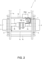
FIG. 2] FIG. 2 is a top view showing the electric wire portion connecting the first unit and the second unit of the vehicle according to the embodiment of the present invention. - [
FIG. 3] FIG. 3 shows side views each showing an attachment position of a torque rod according to the embodiment of the present invention. - [
FIG. 4] FIG. 4 is an enlarged view of the electric wire portion shown inFIG. 2 . - [
FIG. 5] FIG. 5 is a diagram showing a modification of the vehicle according to the embodiment of the present invention. - Hereinafter, an embodiment of the present invention will be described with reference to the accompanying drawings.
- A vehicle V according to the present embodiment is an electric vehicle using a motor as a drive source. As shown in
FIGS. 1 to 4 , the vehicle V includes aframe 1, anaxle 2,vehicle wheels 3, a plurality ofleaf springs 4, anelectric unit 5 as a first unit, and acontrol unit 6 as a second unit. - As shown in
FIGS. 1 and2 , theframe 1 includes a pair ofside members 1a extending in a front-rear direction of the vehicle V at an interval, and a plurality ofcross members 1b each extending in a width direction of the vehicle V and each having both ends respectively connected to the pair ofside members 1a. Eachside member 1a and eachcross member 1b are made of, for example, a steel material or an aluminum material. - The
axle 2 includes aright axle 2a and aleft axle 2b. Thevehicle wheels 3 are attached to end portions of theright axle 2a and theleft axle 2b, respectively. Theaxle 2 dynamically connects theelectric unit 5 and thevehicle wheels 3 located downstream of a power transmission path. - The
axle 2 is suspended from theframe 1 via the plurality of stackedleaf springs 4. That is, the vehicle V has a rigid axle type suspension structure. Further, theaxle 2 is connected to thecross members 1b viatorque rods 7 as rods extending in a direction intersecting theaxle 2. Both ends of eachtorque rod 7 are swingably supported by brackets respectively attached to theaxle 2 and thecross member 1b. - The
electric unit 5 is attached onto theaxle 2. Theelectric unit 5 includes, in a case, a rotary electric machine M and a differential gear (not shown) that distributes an output of the rotary electric machine M to theright axle 2a and theleft axle 2b. - The rotary electric machine M functions as the drive source of the vehicle V. The rotary electric machine M is implemented by, for example, a three-phase AC permanent magnet synchronous motor. The rotary electric machine M is driven by electric power supplied from a battery (not shown) provided in a vehicle body via the
control unit 6. Rotational power generated by the rotary electric machine M is transmitted to thevehicle wheels 3 via the differential gear (not shown), theright axle 2a, and theleft axle 2b. - Further, the
electric unit 5 has a regeneration function of receiving the rotational power from thevehicle wheels 3 and generating electric power for charging the battery during deceleration or braking of the vehicle V. - An
inverter device 6a having an inverter circuit and a converter circuit is mounted in thecontrol unit 6. In the vehicle V, thecontrol unit 6 is attached to a lower portion of the vehicle body, for example, in the vicinity of thecross member 1b. Theelectric unit 5 and thecontrol unit 6 are electrically connected by a wire harness 8 (electric wire). - As described above, since the vehicle V has the rigid axle type suspension structure, for example, when the vehicle V travels on a rough road or the like, the
axle 2 vigorously swings. At this time, since theelectric unit 5 is attached onto theaxle 2, theelectric unit 5 also vigorously swings. When theelectric unit 5 vigorously swings, thewire harness 8, which connects thecontrol unit 6 provided in the vehicle body and theelectric unit 5 attached onto theaxle 2, vigorously swings, and the durability of thewire harness 8 and connector portions of thewire harness 8 may decrease. - Therefore, in the vehicle V according to the present embodiment, in order to prevent the
wire harness 8 from vigorously swinging, thewire harness 8 is routed along theaxle 2, thetorque rod 7, and thecross member 1b. Hereinafter, a routing method of thewire harness 8 will be specifically described with reference toFIG. 4. FIG. 4 is an enlarged view of a portion in which thewire harness 8 is routed shown inFIG. 2 . - As shown in
FIG. 4 , thewire harness 8 includes afirst wiring portion 8a routed along theright axle 2a, asecond wiring portion 8c routed along thetorque rod 7, athird wiring portion 8e routed along thecross member 1b, afirst bent portion 8b connecting thefirst wiring portion 8a and thesecond wiring portion 8c, and asecond bent portion 8d connecting thesecond wiring portion 8c and thethird wiring portion 8e. - The
first wiring portion 8a and thefirst bent portion 8b are electrically connected by oneconnection portion 9 attached to theright axle 2a. Thefirst bent portion 8b and thesecond wiring portion 8c, and thesecond wiring portion 8c and thesecond bent portion 8d are electrically connected byconnection portions 9 attached to thetorque rod 7. Thesecond bent portion 8d and thethird wiring portion 8e are electrically connected by oneconnection portion 9 attached to thecross member 1b. Eachconnection portion 9 is a member that electrically connects adjacent wires to each other, and is implemented by a connector, a terminal block, or the like. - The
first bent portion 8b is a portion that absorbs a tensile force or a compression force acting on the connection portions with thefirst wiring portion 8a and thesecond wiring portion 8c when theaxle 2 and thetorque rod 7 are relatively displaced. Thefirst bent portion 8b is formed by bending the electric wire. Preferably, thefirst bent portion 8b is formed to bend the electric wire in a direction away from thevehicle wheel 3. By forming thefirst bent portion 8b to be bent in the direction away from thevehicle wheel 3 in this manner, for example, when thefirst bent portion 8b is bent, it is possible to prevent thefirst bent portion 8b from coming into contact with thevehicle wheel 3 or a rotatable element rotating together with thevehicle wheel 3 such as a brake (not shown). - The
second bent portion 8d is a portion that absorbs a tensile force or a compression force acting on the connection portions with thesecond wiring portion 8c and thethird wiring portion 8e when thetorque rod 7 and the frame 1 (cross member 1b) are relatively displaced. Thesecond bent portion 8d is formed by bending the electric wire. Preferably, thesecond bent portion 8d is formed to bend the electric wire in the direction away from thevehicle wheel 3. By forming thesecond bent portion 8d to be bent in the direction away from thevehicle wheel 3 in this manner, for example, when thesecond bent portion 8d is bent, it is possible to prevent thesecond bent portion 8d from coming into contact with thevehicle wheel 3 or the rotatable element rotating together with thevehicle wheel 3 such as a brake (not shown). - In this way, in the vehicle V according to the present embodiment, the
wire harness 8 is routed along theaxle 2, thetorque rod 7, and thecross member 1b, and is supported by theconnection portions 9 attached to theaxle 2, thetorque rod 7, and thecross member 1b. Accordingly, when the vehicle V vigorously vibrates, thewire harness 8 can be prevented from vigorously swinging. - According to the above embodiment, the case in which the
wire harness 8 is routed along theaxle 2, thetorque rod 7, and thecross member 1b by using theconnection portions 9 attached to theaxle 2, thetorque rod 7, and thecross member 1b has been described as an example, but the present invention is not limited thereto, for example, thewire harness 8 may be fixed to outer peripheral surfaces of theaxle 2, thetorque rod 7, and thecross member 1b by other fixing means such as binding bands. In this case, theelectric unit 5 and thecontrol unit 6 may be connected by onewire harness 8, and theconnection portions 9 may be provided. Also in this case, by providing portions corresponding to the firstbent portion 8b and the secondbent portion 8d, it is possible to absorb the tensile force or the compression force caused by the relative displacement among theaxle 2, thetorque rod 7, and thecross member 1b. - Further, according to the above embodiment, the case in which the
wire harness 8 is routed along thetorque rod 7 has been described as an example, but when there is a member (for example, a lateral rod, an upper ring, or a lower link) that connects theaxle 2 and theframe 1, thewire harness 8 may be routed along the member or routed to pass through the interior of the member. - Further, the
wire harness 8 may be routed to pass through the interior of theaxle 2 or thetorque rod 7. In this case, an electric wire may be routed inside theaxle 2 or thetorque rod 7, and as shown inFIG. 5 , bus bars B may be routed inside thetorque rod 7 instead of the electric wire. In the case in which the bus bars B are routed, a resin R is filled in thetorque rod 7, thereby preventing the bus bars B from rattling in thetorque rod 7. Further, the resin R can ensure insulation between the bus bars B or between the bus bars B and thetorque rod 7. The same structure can be adopted for the routing of thewire harness 8 in theaxle 2. - In addition, according to the above embodiment, the suspension structure using the
leaf springs 4 has been described as an example, but the present invention is also applicable to a suspension structure using a coil spring and a shock absorber. - The configurations, functions, and effects of the embodiment of the present invention configured as described above will be collectively described.
- (1) The vehicle V includes the electric unit 5 (first unit) on which the rotary electric machine M is mounted, the control unit 6 (second unit) on which the
inverter device 6a (inverter) is mounted, the wire harness 8 (electric wire) that electrically connects the electric unit 5 (first unit) and the control unit 6 (second unit), and thevehicle wheels 3 that are dynamically connected downstream of the electric unit 5 (first unit) via theaxle 2, in which the wire harness 8 (electric wire) has the portion (first wiring portion 8a) routed along theaxle 2. - According to this configuration, the wire harness 8 (electric wire) is not extended in a straight line from the electric unit 5 (first unit) toward the control unit 6 (second unit), but the wire harness 8 (electric wire) is provided to extend from the electric unit 5 (first unit) toward the
vehicle wheel 3 in a detoured manner. At this time, since the wire harness 8 (electric wire) is routed along theaxle 2, it is possible to restrain the swing of the wire harness 8 (electric wire). Accordingly, the durability of the wire harness 8 (electric wire) connecting the electric unit 5 (first unit) and the control unit 6 (second unit) can be improved. - When the wire harness 8 (electric wire) is routed along an outer surface of the
axle 2, the bending can be reduced by attaching theconnection portions 9 to theaxle 2. On the other hand, when the wire harness 8 (electric wire) is located inside theaxle 2, it is possible to further reduce the influence of the swing of the wire harness 8 (electric wire). - (2) The vehicle V includes the torque rods 7 (rod) that extend in the direction intersecting the
axle 2, and the wire harness 8 (electric wire) has the portion (second wiring portion 8c) routed along the torque rod 7 (rod). - According to this configuration, since the wire harness 8 (electric wire) is routed along the torque rod 7 (rod), it is possible to restrain the swing of the wire harness 8 (electric wire). When the wire harness 8 (electric wire) is routed along an outer surface of the torque rod 7 (rod), the bending can be reduced by attaching the
connection portions 9 to the torque rod 7 (rod). On the other hand, when the wire harness 8 (electric wire) is located inside the torque rod 7 (rod), it is possible to further reduce the influence of the swing of the wire harness 8 (electric wire). - (3) In the vehicle V, the wire harness 8 (electric wire) has the portion passing through the interior of the torque rod 7 (rod).
- According to this configuration, it is possible to further reduce the influence of the swing of the wire harness 8 (electric wire).
- (4) In the vehicle V, the wire harness 8 (electric wire) has the bent portion (first
bent portion 8b) that is bent between the portion (first wiring portion 8a) routed along theaxle 2 and the portion (second wiring portion 8c) routed along the torque rod 7 (rod). - According to this configuration, the portion of the wire harness 8 (electric wire) connecting the
axle 2 and the torque rod 7 (rod) is locally bent, and thus the bent portion can be set to a necessary minimum size, and the connection from theaxle 2 to the torque rod 7 (rod), which extends in the intersecting direction, can be smoothly performed by the bending. In addition, the tensile force or the compression force caused by the relative displacement between theaxle 2 and thetorque rod 7 can be restrained from acting on the wire harness 8 (electric wire). - (5) In the vehicle V, the bent portion (first
bent portion 8b) is bent in the direction away from thevehicle wheel 3. - Although the embodiment of the present invention has been described above, the above embodiment merely exemplifies application examples of the present invention and does not intend to limit the technical scope of the present invention to the specific configurations of the above embodiment.
-
- 1 frame
- 1a side member
- 1b cross member
- 2 axle
- 3 vehicle wheel
- 5 electric unit (first unit)
- 6 control unit (second unit)
- 6a inverter device (inverter)
- 7 torque rod (rod)
- 8 wire harness (electric wire)
- 8a first wiring portion
- 8b first bent portion
- 8c second wiring portion
- 8d second bent portion
- 8e third wiring portion
- 9 connection portion M rotary electric machine
Claims (5)
- A vehicle comprising:a first unit on which a rotary electric machine is mounted;a second unit on which an inverter is mounted;an electric wire that electrically connects the first unit and the second unit; anda vehicle wheel that is dynamically connected downstream of the first unit via an axle, whereinthe electric wire has a portion routed along the axle.
- The vehicle according to claim 1, further comprising:a rod that extends in a direction intersecting the axle, whereinthe electric wire has a portion routed along the rod.
- The vehicle according to claim 2, wherein
the electric wire has a portion passing through the interior of the rod. - The vehicle according to claim 2 or 3, wherein
the electric wire has a bent portion bent between the portion routed along the axle and the portion routed along the rod. - The vehicle according to claim 4, wherein
the bent portion is bent in a direction away from the vehicle wheel.
Applications Claiming Priority (2)
| Application Number | Priority Date | Filing Date | Title |
|---|---|---|---|
| JP2022108526 | 2022-07-05 | ||
| PCT/JP2023/017895 WO2024009606A1 (en) | 2022-07-05 | 2023-05-12 | Vehicle |
Publications (3)
| Publication Number | Publication Date |
|---|---|
| EP4552877A1 true EP4552877A1 (en) | 2025-05-14 |
| EP4552877A4 EP4552877A4 (en) | 2025-10-29 |
| EP4552877B1 EP4552877B1 (en) | 2026-04-15 |
Family
ID=89453094
Family Applications (1)
| Application Number | Title | Priority Date | Filing Date |
|---|---|---|---|
| EP23833571.5A Active EP4552877B1 (en) | 2022-07-05 | 2023-05-12 | Vehicle |
Country Status (5)
| Country | Link |
|---|---|
| US (1) | US20250388182A1 (en) |
| EP (1) | EP4552877B1 (en) |
| JP (1) | JP7825050B2 (en) |
| CN (1) | CN119497675A (en) |
| WO (1) | WO2024009606A1 (en) |
Family Cites Families (12)
| Publication number | Priority date | Publication date | Assignee | Title |
|---|---|---|---|---|
| JP2005075319A (en) | 2003-09-04 | 2005-03-24 | Nissan Motor Co Ltd | Wiring structure for power supply to axle side electrical equipment |
| JP3951138B2 (en) | 2004-02-26 | 2007-08-01 | 三菱自動車工業株式会社 | Hybrid vehicle power unit and hybrid vehicle |
| JP4985721B2 (en) | 2009-07-17 | 2012-07-25 | 日産自動車株式会社 | Motor room structure |
| JP4826670B2 (en) * | 2009-11-06 | 2011-11-30 | 株式会社豊田自動織機 | Towing tractor |
| JP2012183903A (en) * | 2011-03-04 | 2012-09-27 | Suzuki Motor Corp | Routing structure of high-voltage cable in vehicle |
| JP2013159224A (en) * | 2012-02-06 | 2013-08-19 | Nissan Motor Co Ltd | Wire harness routing structure of power source integration type wheel |
| WO2017114422A1 (en) * | 2015-12-31 | 2017-07-06 | Byd Company Limited | Vehicle and electric drive axle assembly for vehicle |
| JP6918459B2 (en) * | 2016-04-06 | 2021-08-11 | Ntn株式会社 | Wiring structure of in-wheel motor power line and in-wheel motor drive |
| US11548383B2 (en) * | 2019-11-12 | 2023-01-10 | Dana Automotive Systems Group, Llc | Electric drive axle in a vehicle |
| CN117341602A (en) | 2020-02-20 | 2024-01-05 | 住友电装株式会社 | Wiring harness and wiring harness layout structure |
| JP7456315B2 (en) * | 2020-07-13 | 2024-03-27 | 住友電装株式会社 | Wheel side equipment and undercarriage wiring equipment |
| NL2026916B1 (en) * | 2020-11-17 | 2022-07-01 | Daf Trucks Nv | Rear axle with integrated electric motor |
-
2023
- 2023-05-12 US US18/879,049 patent/US20250388182A1/en active Pending
- 2023-05-12 CN CN202380050940.9A patent/CN119497675A/en active Pending
- 2023-05-12 WO PCT/JP2023/017895 patent/WO2024009606A1/en not_active Ceased
- 2023-05-12 JP JP2024531936A patent/JP7825050B2/en active Active
- 2023-05-12 EP EP23833571.5A patent/EP4552877B1/en active Active
Also Published As
| Publication number | Publication date |
|---|---|
| WO2024009606A1 (en) | 2024-01-11 |
| US20250388182A1 (en) | 2025-12-25 |
| JP7825050B2 (en) | 2026-03-05 |
| EP4552877A4 (en) | 2025-10-29 |
| JPWO2024009606A1 (en) | 2024-01-11 |
| EP4552877B1 (en) | 2026-04-15 |
| CN119497675A (en) | 2025-02-21 |
Similar Documents
| Publication | Publication Date | Title |
|---|---|---|
| CN103201139B (en) | The cable arrangement structure of vehicle | |
| JP5589772B2 (en) | Electric parts mounting structure for electric vehicles | |
| EP4092880B1 (en) | ELECTRIC VEHICLE WITH AN ARRANGEMENT CONSISTING OF A DRIVE UNIT AND A POWER SUPPLY UNIT | |
| CN102673492B (en) | The wire structures of the high-tension cable in vehicle | |
| JP2008001241A (en) | Wire wiring structure | |
| JP5900012B2 (en) | Powertrain structure for electric vehicles | |
| JP2025147005A (en) | Undercarriage wiring module and wiring structure for undercarriage wiring module | |
| JP2025134962A (en) | Wire harness and wiring structure for wire harness | |
| EP4552877B1 (en) | Vehicle | |
| JP2006027310A (en) | Support structure for in-wheel motor for vehicle | |
| US12552336B2 (en) | Undercarriage wiring module and routing structure of undercarriage wiring module | |
| JP2019111837A (en) | Loading structure of power control unit | |
| JP2013159188A (en) | Wire harness routing structure of steering wheel | |
| JP5396907B2 (en) | In-vehicle motor cable routing structure | |
| JP2005075319A (en) | Wiring structure for power supply to axle side electrical equipment | |
| JP2007014090A (en) | High-voltage harness wiring structure for electric vehicles | |
| CN115835971A (en) | Wheel-side device and chassis wiring device | |
| JP7272133B2 (en) | Vehicle cable mounting structure | |
| JP7798687B2 (en) | Stabilizer unit | |
| EP4574487B1 (en) | Battery electric vehicle | |
| JP2024021325A (en) | In-wheel motor wiring structure | |
| JP2022139717A (en) | in-wheel motor vehicle | |
| CN121311388A (en) | Wiring harness installation structure | |
| CN118510684A (en) | Wiring module for traveling system | |
| JP4407645B2 (en) | Rigid suspension system for motorized vehicles |
Legal Events
| Date | Code | Title | Description |
|---|---|---|---|
| STAA | Information on the status of an ep patent application or granted ep patent |
Free format text: STATUS: THE INTERNATIONAL PUBLICATION HAS BEEN MADE |
|
| PUAI | Public reference made under article 153(3) epc to a published international application that has entered the european phase |
Free format text: ORIGINAL CODE: 0009012 |
|
| STAA | Information on the status of an ep patent application or granted ep patent |
Free format text: STATUS: REQUEST FOR EXAMINATION WAS MADE |
|
| 17P | Request for examination filed |
Effective date: 20241219 |
|
| AK | Designated contracting states |
Kind code of ref document: A1 Designated state(s): AL AT BE BG CH CY CZ DE DK EE ES FI FR GB GR HR HU IE IS IT LI LT LU LV MC ME MK MT NL NO PL PT RO RS SE SI SK SM TR |
|
| DAV | Request for validation of the european patent (deleted) | ||
| DAX | Request for extension of the european patent (deleted) | ||
| A4 | Supplementary search report drawn up and despatched |
Effective date: 20250929 |
|
| RIC1 | Information provided on ipc code assigned before grant |
Ipc: B60K 1/00 20060101AFI20250923BHEP Ipc: B60K 6/40 20071001ALI20250923BHEP Ipc: B60K 17/12 20060101ALI20250923BHEP Ipc: B60R 16/02 20060101ALI20250923BHEP |
|
| GRAP | Despatch of communication of intention to grant a patent |
Free format text: ORIGINAL CODE: EPIDOSNIGR1 |
|
| STAA | Information on the status of an ep patent application or granted ep patent |
Free format text: STATUS: GRANT OF PATENT IS INTENDED |
|
| GRAS | Grant fee paid |
Free format text: ORIGINAL CODE: EPIDOSNIGR3 |
|
| GRAA | (expected) grant |
Free format text: ORIGINAL CODE: 0009210 |
|
| STAA | Information on the status of an ep patent application or granted ep patent |
Free format text: STATUS: THE PATENT HAS BEEN GRANTED |
|
| INTG | Intention to grant announced |
Effective date: 20260220 |
|
| AK | Designated contracting states |
Kind code of ref document: B1 Designated state(s): AL AT BE BG CH CY CZ DE DK EE ES FI FR GB GR HR HU IE IS IT LI LT LU LV MC ME MK MT NL NO PL PT RO RS SE SI SK SM TR |
|
| REG | Reference to a national code |
Ref country code: CH Ref legal event code: F10 Free format text: ST27 STATUS EVENT CODE: U-0-0-F10-F00 (AS PROVIDED BY THE NATIONAL OFFICE) Effective date: 20260415 |
|
| REG | Reference to a national code |
Ref country code: DE Ref legal event code: R096 Ref document number: 602023015478 Country of ref document: DE |