EP4552623A1 - Shunt for fibrous encapsulation in glaucoma patients - Google Patents
Shunt for fibrous encapsulation in glaucoma patients Download PDFInfo
- Publication number
- EP4552623A1 EP4552623A1 EP23835776.8A EP23835776A EP4552623A1 EP 4552623 A1 EP4552623 A1 EP 4552623A1 EP 23835776 A EP23835776 A EP 23835776A EP 4552623 A1 EP4552623 A1 EP 4552623A1
- Authority
- EP
- European Patent Office
- Prior art keywords
- shunt
- main body
- bleb
- support member
- fibrous encapsulation
- Prior art date
- Legal status (The legal status is an assumption and is not a legal conclusion. Google has not performed a legal analysis and makes no representation as to the accuracy of the status listed.)
- Pending
Links
Images



Classifications
-
- A—HUMAN NECESSITIES
- A61—MEDICAL OR VETERINARY SCIENCE; HYGIENE
- A61F—FILTERS IMPLANTABLE INTO BLOOD VESSELS; PROSTHESES; DEVICES PROVIDING PATENCY TO, OR PREVENTING COLLAPSING OF, TUBULAR STRUCTURES OF THE BODY, e.g. STENTS; ORTHOPAEDIC, NURSING OR CONTRACEPTIVE DEVICES; FOMENTATION; TREATMENT OR PROTECTION OF EYES OR EARS; BANDAGES, DRESSINGS OR ABSORBENT PADS; FIRST-AID KITS
- A61F9/00—Methods or devices for treatment of the eyes; Devices for putting in contact-lenses; Devices to correct squinting; Apparatus to guide the blind; Protective devices for the eyes, carried on the body or in the hand
- A61F9/007—Methods or devices for eye surgery
- A61F9/00781—Apparatus for modifying intraocular pressure, e.g. for glaucoma treatment
-
- A—HUMAN NECESSITIES
- A61—MEDICAL OR VETERINARY SCIENCE; HYGIENE
- A61F—FILTERS IMPLANTABLE INTO BLOOD VESSELS; PROSTHESES; DEVICES PROVIDING PATENCY TO, OR PREVENTING COLLAPSING OF, TUBULAR STRUCTURES OF THE BODY, e.g. STENTS; ORTHOPAEDIC, NURSING OR CONTRACEPTIVE DEVICES; FOMENTATION; TREATMENT OR PROTECTION OF EYES OR EARS; BANDAGES, DRESSINGS OR ABSORBENT PADS; FIRST-AID KITS
- A61F9/00—Methods or devices for treatment of the eyes; Devices for putting in contact-lenses; Devices to correct squinting; Apparatus to guide the blind; Protective devices for the eyes, carried on the body or in the hand
- A61F9/0008—Introducing ophthalmic products into the ocular cavity or retaining products therein
- A61F9/0017—Introducing ophthalmic products into the ocular cavity or retaining products therein implantable in, or in contact with, the eye, e.g. ocular inserts
Definitions
- the present disclosure relates to a shunt for fibrous encapsulation of glaucoma patients. More particularly, the present disclosure relates to a shunt which is mounted in a fibrous encapsulation formed at a surgical site after a glaucoma surgery, such as trabeculectomy and glaucoma drainage device implantation, and drains aqueous humor within the fibrous encapsulation.
- a glaucoma surgery such as trabeculectomy and glaucoma drainage device implantation
- Glaucoma is an eye disease in which the circulation of aqueous humor is abnormal, causing an increase in an amount of the aqueous humor in the eye and an increase in intraocular pressure.
- the optic nerve is compressed and the blood flow to the eye decreases, causing degeneration of the optic nerve and retina. This may result in vision loss or visual field defects and may be accompanied by severe pain.
- glaucoma can be managed through pharmacological treatment and surgical treatment.
- the pharmacological treatment is performed using drugs which suppress the production of aqueous humor or increase the drainage of aqueous humor.
- the pharmacological treatment is generally performed first, and the purpose of pharmacological treatment is to slow the progression of vision loss due to glaucoma.
- the pharmacological treatment has the disadvantage of being difficult to sufficiently alleviate the increase in intraocular pressure caused by glaucoma as glaucoma progresses, and a high incidence of side effects to the drug (conjunctivitis, uveitis, hypersensitivity of the skin around the eye, or the like).
- the surgical treatment as a method of increasing aqueous humor drainage involves a surgery to divert aqueous humor, which is not drained from an anterior chamber of the eye, to subconjunctival or subtenon to thereby allow the aqueous humor to be absorbed through a route other than the eyeball.
- the surgical treatment includes trabeculectomy, glaucoma drainage device implantation, or the like.
- the trabeculectomy is a surgery to drain aqueous humor by creating an aqueous humor bypass without implantation of a device.
- the glaucoma drainage device implantation is a surgery to drain an aqueous humor of an anterior chamber 110 by implanting a glaucoma drainage device 150 including an aqueous humor bypass.
- a side of the glaucoma drainage device 150 may be located in the anterior chamber 110.
- the side of the glaucoma drainage device 150 may be in the form of a tube.
- Aqueous humor in the anterior chamber 110 may flow into the side of the glaucoma drainage device 150.
- a direction in which the aqueous humor of the anterior chamber 110 flows into the glaucoma drainage device 150 may be referred to as a first direction F1.
- Another side of the glaucoma drainage device 150 may be located outside a sclera 120.
- the aqueous humor within the glaucoma drainage device 150 may be drained to the other side of the glaucoma drainage device 150.
- a direction in which the aqueous humor within the glaucoma drainage device 150 is drained to a space between the sclera 120 and a conjunctiva 130 may be referred to as a second direction F2.
- a bleb may be formed around the glaucoma drainage device 150 after several weeks.
- the bleb around the glaucoma drainage device 150 may be referred to as a first bleb 140.
- the aqueous humor widely spread by the first bleb 140 may be absorbed into subconjunctival or subtenon and reabsorbed into the blood flow.
- Fibrosis of the first bleb 140 may progress over time.
- An encapsulation of the fibrosed first bleb 140 may be referred to as a fibrous encapsulation.
- the causes of fibrosis of the first bleb 140 include a reaction to surgical stimulation, a preservative of antiglaucoma eye drops used before and after surgery, an inflammatory factor inherent in aqueous humor of a glaucoma patient, a reaction to stimulation according to the flow of aqueous humor, or the like.
- the fibrosed first bleb 140 impedes the flow of the aqueous humor, the aqueous humor within the first bleb 140 cannot escape, which may cause the first bleb 140 to swell. This is a main cause of increased intraocular pressure.
- methods such as using drugs which delay the fibrosis of the first bleb 140 during or after surgery, surgically removing an already fibrosed part, or implanting the glaucoma drainage device 150 into another part of the anterior chamber 110, are implemented.
- the method of delaying the fibrosis of the first bleb 140 using the drugs has a problem of causing side effects (conjunctival ulcer, cataract, or the like) to the drugs themselves.
- the method of implanting the glaucoma drainage device 150 into another part of the anterior chamber 110 is a method of performing an additional surgery on an eyeball 100 which has already experienced an inflammatory reaction, and thus there is a problem that there is a high risk of inflammation or infection.
- the implantation of the glaucoma drainage device 150 is performed under general anesthesia for a long time, a physical burden on the patient may increase, and the time and financial burden of the surgery may increase.
- An object of Korean patent application publication No. 10-2007-0035529 entitled 'Ophthalmic implant, method of manufacturing the same, and method of using the same' (hereinafter, 'patent document 1'), Korean patent application publication No. 10-2020-0118291 entitled 'Shunt stent for eyeball drainage' (hereinafter, 'patent document 2'), and Korean patent application publication No. 10-2022-0000690 entitled 'Glaucoma drainage device with adjustable tube diameter' (hereinafter, 'patent document 3') is to divert the aqueous humor of the anterior chamber 110 to subconjunctival and drain the aqueous humor.
- the devices of the patent documents 1 to 3 are mounted on the eyeball 100, they are formed in a shape suitable for mounting on the spherical eyeball 100.
- the devices of the patent documents 1 to 3 are mounted between the inside of the spherical eyeball 100 and the subconjunctival.
- the first bleb 140 is formed in a convex shape protruding from the sclera 120, and has a feature in that a height protruding from the sclera 120 decreases and the curvature decreases as the aqueous humor within the first bleb 140 is drained.
- the shape of the first bleb 140 is formed in an identical or similar shape regardless of a type of the glaucoma drainage device 150 mounted in the eyeball 100.
- the eyeball 100 and the first bleb 140 are different from each other in the shape and the feature, a device suitable for mounting in the first bleb 140 is required.
- An object of the present disclosure is to address the above-described and other problems.
- Another object of the present disclosure is to minimally invasively drain aqueous humor within a bleb.
- Another object of the present disclosure is to provide a shunt for preventing conjunctival thinning.
- Another object of the present disclosure is to provide a shunt for smoothly draining aqueous humor.
- Another object of the present disclosure is to provide a shunt which can be mounted in plural.
- a shunt comprising a main body penetrating a fibrous encapsulation of a bleb formed between a sclera and a conjunctiva and a flow path penetrating the main body and draining an aqueous humor within the bleb to an outside of the bleb.
- the shunt may further comprise a first support member connected to a front of the main body and positioned outside the fibrous encapsulation, and a second support member connected to a rear of the main body and positioned inside the fibrous encapsulation.
- the main body may include a lower surface facing the sclera, and the flow path may penetrate the main body from the front to the rear.
- a shunt which can minimally invasively drain aqueous humor within a bleb.
- a shunt which prevents conjunctival thinning.
- a shunt which smoothly drains aqueous humor.
- a shunt which that can be mounted in a fibrous encapsulation in plural.
- a singular expression can include a plural expression as long as it does not have an apparently different meaning in context.
- a specific order of processes may be performed differently from the order described. For example, two consecutively described processes may be performed substantially at the same time, or performed in the order opposite to the described order.
- the following embodiments when layers, areas, components, or the like are connected, the following embodiments include both the case where layers, areas, and components are directly connected, and the case where layers, areas, and components are indirectly connected to other layers, areas, and components intervening between them.
- FIG. 2 illustrates that a shunt 200 according to an embodiment of the present disclosure is mounted in the first bleb 140 of FIG. 1 .
- FIG. 3 is a perspective view illustrating the shunt 200 of FIG. 2 .
- the first bleb 140 may be formed around a glaucoma drainage device 150.
- the first bleb 140 may include aqueous humor drained from an anterior chamber 110 or the glaucoma drainage device 150.
- the first bleb 140 may be formed in a convex shape protruding from a sclera 120.
- the first bleb 140 may include a first fibrous encapsulation 141 surrounding the first bleb 140.
- the first fibrous encapsulation 141 may be formed as an encapsulation of the first bleb 140 is fibrosed.
- the first bleb 140 may include a first internal space 142 formed between the first fibrous encapsulation 141 and the sclera 120.
- the aqueous humor may be filled in the first internal space 142.
- the first bleb 140 may convexly protrude on the sclera 120.
- the first internal space 142 may be formed between the sclera 120 and the first fibrous encapsulation 141.
- the shunt 200 may extend from an end 201 to another end 202.
- the end 201 of the shunt 200 may be a front end of the shunt 200.
- the other end 202 of the shunt 200 may be a rear end of the shunt 200.
- a longitudinal direction of the shunt 200 may be parallel to a direction from the end 201 to the other end 202.
- the longitudinal direction of the shunt 200 may be a front-rear direction.
- the end 201 of the shunt 200 may be directed toward the outside of the first bleb 140.
- the end 201 of the shunt 200 may be positioned outside the first fibrous encapsulation 141.
- the other end 202 of the shunt 200 may be directed toward the inside of the first bleb 140.
- the other end 202 of the shunt 200 may be positioned inside the first fibrous encapsulation 141.
- the other end of the shunt 200 may be positioned in the first internal space 142.
- the shunt 200 may include a main body 210.
- the main body 210 may extend in the longitudinal direction of the shunt 200.
- the main body 210 may be formed in a rectangular parallelepiped shape.
- the main body 210 may be arranged to penetrate the first fibrous encapsulation 141.
- a lower surface (lower side in FIG. 3 ) of the main body 210 may be arranged to face the sclera 120.
- the main body 210 may be formed longer than a thickness of the first fibrous encapsulation 141. Hence, a side of the main body 210 may be located outside the first fibrous encapsulation 141, and another side of the main body 210 may be located inside the first fibrous encapsulation 141. A width of the main body 210 may be greater than a height of the main body 210.
- the shunt 200 may include a first support member 220.
- the first support member 220 may be connected to the side of the main body 210.
- the first support member 220 may be located outside the first bleb 140.
- the first support member 220 may be located outside the first fibrous encapsulation 141.
- the first support members 220 may be respectively formed on opposite sides of the main body 210 facing each other in a width direction of the main body 210.
- the first support members 220 may extend in the width direction of the main body 210 on the opposite sides of the main body 210.
- the first support members 220 may extend in a width direction of the first bleb 140 on the opposite sides of the main body 210.
- the first support members 220 may be caught on an outer surface of the first fibrous encapsulation 141 to prevent the shunt 200 from falling into the inside of the first fibrous encapsulation 141.
- the front of the main body 210 may be supported on the outer surface of the first fibrous encapsulation 141 by the first support members 220.
- the first support member 220 may be located between the first fibrous encapsulation 141 and the conjunctiva 130. The first support member 220 may be in contact with the outer surface of the first fibrous encapsulation 141. The first support member 220 may be in contact with the conjunctiva 130.
- the shunt 200 may include a second support member 230.
- the second support member 230 may be connected to the other side of the main body 210.
- the second support member 230 may be located inside the first bleb 140.
- the second support member 230 may be located inside the first fibrous encapsulation 141.
- the second support members 230 may be respectively formed on opposite sides of the main body 210 facing each other in the width direction of the main body 210.
- the second support members 230 may extend on the opposite sides of the main body 210 in the width direction of the main body 210.
- the second support members 230 may extend on the opposite sides of the main body 210 in the width direction of the first bleb 140.
- the second support members 230 may be caught on an inner surface of the first fibrous encapsulation 141 to prevent the shunt 200 from falling into the outside of the first fibrous encapsulation 141.
- the rear of the main body 210 may be supported on the inner surface of the first fibrous encapsulation 141 by the second support members 230.
- a height HS of the shunt 200 may be less than a height of the glaucoma drainage device 150.
- the height of the main body 210, a height of the first support member 220, and a height of the second support member 230 may be the same as the height HS of the shunt 200.
- the shunt 200 may include a flow path 240 formed in the main body 210.
- the flow path 240 may be formed by penetrating the main body 210 in the longitudinal direction.
- the flow path 240 may be formed by penetrating the main body 210 in the front-rear direction.
- the flow path 240 may be formed as a rectangular hole.
- the flow path 240 may be formed as an oval hole.
- the flow path 240 may be formed as a semi-oval hole.
- the flow path 240 may be formed sufficiently wide so that the aqueous humor within the first bleb 140 can be drained to the outside of the first bleb 140 through the flow path 240.
- a width of the flow path 240 may greater than a height of the flow path 240.
- the width of the flow path 240 may be formed sufficiently long within a range where the center of the flow path 240 is not pressed by an external force acting on the shunt 200.
- the external force acting on the shunt 200 may include a force of surrounding tissue of the shunt 200, a force blinking the eyeball 100, or the like.
- the inside of the first bleb 140 and the outside of the first bleb 140 may be connected by the flow path 240.
- the aqueous humor of the first internal space 142 can be drained to the outside of the first bleb 140.
- the first internal space 142 may be connected to a space formed between the first bleb 140 and the conjunctiva 130 by the flow path 240. Because the aqueous humor of the first internal space 142 is in a high pressure state, the aqueous humor may be drained to a low pressure side through the flow path 240.
- the aqueous humor of the first internal space 142 may be drained to the space formed between the first bleb 140 and the conjunctiva 130.
- the shunt 200 may include an installation groove 250 formed by being surrounded by the main body 210, the first support member 220, and the second support member 230. Both sides of the installation groove 250 may be open in a height direction (up-down direction) of the shunt 200.
- the installation groove 250 may be formed so that the opposite side of the flow path 240 is open in a width direction of the shunt 200.
- the first fibrous encapsulation 141 may be accommodated in the installation groove 250. Hence, the first support member 220 located outside the first fibrous encapsulation 141 may not enter the first internal space 142. As a result, the second support member 230 located inside the first fibrous encapsulation 141 may not fall out of the first bleb 140.
- Edges of the shunt 200 may be rounded. The rounding can minimize damage to the conjunctiva 130 caused by the edges of the shunt 200. If the conjunctiva 130 is damaged, fine tissues within the conjunctiva 130 may be stimulated, thereby promoting ulceration or fibrosis.
- Edges of the flow path 240 may be rounded. The rounding can improve an impact strength or a fracture resistance around the flow path 240.
- the shunt 200 may be formed by including a silicone material.
- the main body 210, the first support member 220, and the second support member 230 may be formed by including a silicone material.
- the flexibility of the shunt 200 can be improved, and a foreign body sensation caused by the shunt 200 when the eyeball 100 or the eyelid moves can be reduced.
- the risk of the eyeball 100 being damaged by the shunt 200 can be reduced.
- the shunt 200 is easy to be installed and removed, the shunt 200 can be installed and removed with minimum procedures in a short period of time.
- the shunt 200 may be formed by including a sterilized silicone material.
- the shunt 200 may be formed by including a medical grade implantable silicone material that can be implanted into the human body.
- the shunt 200 may be formed by including MED-4830 manufactured by Nusil Technology LLC.
- FIG. 4 is a plan view of the shunt 200 of FIG. 3 .
- a thickness of the first support member 220 is a length of the first support member 220 and may be referred to as a first thickness t1.
- a thickness of the second support member 230 is a length of the second support member 230 and may be referred to as a second thickness t2.
- the first thickness t1 may be less than the second thickness t2. Hene, the foreign body sensation caused by the first support member 220 located outside the first bleb 140 can be reduced.
- the second thickness t2 may be thicker than the first thickness t1.
- the second support member 230 located inside the first bleb 140 may have a difficulty falling out of the first fibrous encapsulation 141. If the second thickness t2 is too thin, the second support member 230 may easily fold toward the other end 202 of the main body 210. Therefore, the second support member 230 may fold and fall out of the first bleb 140 due to a pressure inside the first bleb 140 or the external force applied to the shunt 200.
- the second support member 230 may sufficiently extend from the main body 210.
- the first thickness t1 may be similar to the second thickness t2. Hene, it can be difficult for the first support member 220 to enter the inside of the first fibrous encapsulation 141.
- the shape of the first support member 220 and the shape of the second support member 230 are similar, and thus the inside and the outside of the shunt 200 may be changed and used.
- FIG. 5 is a plan view illustrating a shunt 1200 according to another embodiment of the present disclosure.
- a front surface of a main body 1210 may get closer to a rear surface of the main body 1210 as it goes away from the center of the main body 1210.
- the front surface of the main body 1210 may be formed in a curved shape.
- a front surface of the first support member 1220 may get closer to a rear surface of the first support member 1220 as it goes away from the main body 1210.
- the front surface of the first support member 1220 may be formed in a curved shape and may be continuously formed by being connected to the front surface of the main body 1210.
- the front surface of the main body 1210 and the front surface of the first support member 1220 may be formed in a curved shape which convexly protrudes as they go to the center of the shunt 1200.
- a front surface of the shunt 1200 may be formed in a convex shape.
- FIG. 6 is a front view illustrating a shunt 2200 according to another embodiment of the present disclosure.
- An upper surface of a first support member 2220 may get closer to the sclera 120 (see FIG. 2 ) as it goes away from a main body 2210.
- the upper surface of the first support member 2220 may be formed in a curved surface and connected to an upper surface of the main body 2210.
- a connection part between the upper surface of the first support member 2220 and the upper surface of the main body 2210 may be rounded.
- An upper surface of a front of the main body 2210 may get closer to the sclera 120 as it goes away from the center of the main body 2210 in a width direction.
- the upper surface of the main body 2210 may be formed in a curved surface and may be continuously formed by being connected to the upper surface of the first support member 2220.
- the upper surface of the front of the main body 2210 and the upper surface of the first support member 2220 are positioned close to the conjunctiva 130 (see FIG. 2 ), damage to the conjunctiva 130 (see FIG. 2 ) can be minimized by the shapes of the main body 2210 and the first support member 2220. In addition, a foreign body sensation caused by the main body 2210 and the first support member 2220 can be reduced.
- a second support member (not shown, see '230' of FIG. 3 ) may be formed in the same or similar manner as the first support member 2220.
- the upper surface of the main body 2210 may be entirely formed in the same or similar manner as the upper surface of the front of the main body 2210.
- An upper surface of the second support member may be continuously formed by being connected to an upper surface of a rear of the main body 2210.
- the second support member may be positioned close to an inner surface of the first bleb 140 (see FIG. 2 ), and the main body 2210 may penetrate the first bleb 140. Therefore, damage to the first bleb 140 can be minimized by the shape of the second support member and the main body 2210.
- the aqueous humor of the first internal space 142 may be drained to the outside of the first bleb 140 as illustrated in FIG. 7 .
- the aqueous humor of the first internal space 142 may be drained to a subconjunctival space 160 through the shunt 200.
- a direction in which the aqueous humor of the first internal space 142 is drained to the outside of the first bleb 140 (e.g., the subconjunctival space 160) through the shunt 200 may be referred to as a third direction F3.
- the aqueous humor of the anterior chamber 110 may move through the first direction F1, the second direction F2, and the third direction F3.
- a pressure increase caused by the aqueous humor can be alleviated, and thus a pressure of the first bleb 140 and a pressure (intraocular pressure) of the eyeball 100 (see FIG. 1 ) can be reduced.
- the shunt 200 When the shunt 200 is mounted in the first bleb 140, the shunt 200 may be mounted as close as possible to a connection part between the first bleb 140 and the sclera 120. Hence, the foreign body sensation and damage to the conjunctiva 130 caused by the shunt 200 can be minimized.
- the upper surface of the shunt 200 when the shunt 200 is mounted in the first bleb 140, the upper surface of the shunt 200 may be mounted lower than an upper surface of the glaucoma drainage device 150. Hence, the foreign body sensation and damage to the conjunctiva 130 caused by the shunt 200 can be minimized.
- a height of the first internal space 142 in FIG. 2 may be referred to as a first height H1, and a height of the first internal space 142 in FIG. 7 may be referred to as a second height H2.
- the second height H2 may be lower than the first height H1.
- a new bleb which is a second bleb 170, may be formed outside the shunt 200, as illustrated in FIG. 8 .
- the aqueous humor drained to the outside of the first bleb 140 may be widely spread by the second bleb 170 and absorbed into the blood flow.
- the second bleb 170 may be fibrosed and may not smoothly absorb the aqueous humor.
- the shunt 200 may be additionally mounted in the first bleb 140 or the second bleb 170 to drain the aqueous humor within the first bleb 140 or the second bleb 170.
- the additionally mounted shunt 200 may be mounted at a different location from the previously mounted shunt 200.
- FIG. 9 illustrates that an additional shunt 200' is mounted in the second bleb 170 of FIG. 8 .
- the additional shunt 200' may be mounted in the second bleb 170.
- the additional shunt 200' may be mounted in a second fibrous encapsulation 171 of the second bleb 170.
- the aqueous humor in the second bleb 170 may be drained to the outside of the second bleb 170 by the additional shunt 200'.
- the aqueous humor in a second internal space 172 may be drained to the space between the conjunctiva 130 and the sclera 120 by the additional shunt 200'.
- a direction in which the aqueous humor in the second bleb 170 is drained to the outside of the second bleb 170 by the additional shunt 200' may be referred to as a fourth direction F4.
- the fourth direction F4 may be a direction parallel to the third direction F3.
- the aqueous humor in the anterior chamber 110 may move through the first direction F1, the second direction F2, the third direction F3, and the fourth direction F4.
- a new bleb which is a third bleb 180, may be formed outside the additional shunt 200'.
- the aqueous humor drained from the second bleb 170 to the third bleb 180 may be widely spread by the third bleb 180 and absorbed into the blood flow.
- the third bleb 180 may be fibrosed.
- a third fibrous encapsulation 181 may be formed, and the aqueous humor may accumulate in a third internal space 182.
- FIG. 10 illustrates that an additional shunt 200" is mounted in the first bleb 140 of FIG. 8 .
- the additional shunt 200" may be mounted in the first bleb 140.
- the shunt 200 and the additional shunt 200" may be arranged such that the glaucoma drainage device 150 are located between the shunt 200 and the additional shunt 200".
- the shunt 200 and the additional shunt 200" may be positioned along the perimeter of the cornea. For example, if the shunt 200 is mounted at the 9 o'clock direction of the first bleb 140 (left side in FIG. 10 ), the additional shunt 200" may be mounted at the 3 o'clock direction of the first bleb 140 (right side in FIG. 10 ).
- the additional shunt 200" may be mounted at the 6 o'clock direction of the first bleb 140 (lower side in FIG. 10 ).
- the aqueous humor in the first bleb 140 may be drained to the outside of the first bleb 140 by the additional shunt 200".
- the aqueous humor in the first internal space 142 may be drained to the space between the conjunctiva 130 and the sclera 120 by the additional shunt 200".
- a direction in which the aqueous humor in the first bleb 140 is drained to the outside of the first bleb 140 by the additional shunt 200" may be referred to as a fifth direction F5.
- the fifth direction F5 may form an angle with respect to the third direction F3.
- the fifth direction F5 may be the opposite direction to the third direction F3.
- the aqueous humor in the anterior chamber 110 may move through the first direction F1, the second direction F2, and the third direction F3 or may move through the first direction F1, the second direction F2, and the fifth direction F5.
- a new bleb which is a third bleb 180', may be formed outside the additional shunt 200".
- the aqueous humor drained from the first bleb 140 to the third bleb 180' may be widely spread by the third bleb 180' and absorbed into the blood flow.
- the blebs 140, 170 and 180 may indicate at least one of the first bleb 140, the second bleb 170, and the third bleb 180.
- the plurality of shunts 200 may be mounted in the blebs 140, 170 and 180 which are fibrosed and have a high internal pressure.
- a surgical method of installing the shunt 200 according to an embodiment of the present disclosure to the first bleb 140 formed around the glaucoma drainage device 150 is described below with reference to FIG. 2 .
- the shunt 200 can also be applied to a bleb formed by trabeculectomy, in addition to the blebs 140, 170 and 180 formed by the glaucoma drainage device 150.
- a surgical site may be prepared through a general anesthesia process and sterilization process.
- the surgical site may be exposed using drugs or stay sutures to secure a surgical view.
- a site where the shunt 200 is to be installed may be determined depending on a location of the glaucoma drainage device 150 of a patient. If the glaucoma drainage device 150 is installed on a lateral side of the eyeball 100, an upward site or a downward site of the first bleb 140 may be determined as the site where the shunt 200 is to be installed. The site where the shunt 200 is to be installed may be determined as a site as close to the sclera 120 as possible.
- the conjunctiva 130 may be incised to expose the first bleb 140.
- the conjunctiva 130 at the site where the shunt 200 is installed may be held with conjunctival forceps and may be bluntly dissected with Stevens or Westcott tenotomy scissors to expose a part of the first bleb 140.
- the conjunctiva 130 may be incised while avoiding blood vessels of the conjunctiva 130. However, if it is difficult to avoid the blood vessels of the conjunctiva 130, the conjunctiva 130 may be incised after a hemostatic treatment, such as cauterization, and hemostatic treatment can be applied to any bleeding that occurs during the incision.
- a part of the first fibrous encapsulation 141 of the exposed first bleb 140 may be incised or excised to provide a space for installing the shunt 200.
- a part of the exposed first fibrous encapsulation 141 may be incised or excised using a blade or a special punch to provide a space for installing the shunt 200.
- the first fibrous encapsulation 141 may be incised longer than a widthwise length of the shunt 200.
- the shunt 200 may be mounted in an incision site of the first fibrous encapsulation 141.
- the shunt 200 may be implanted into the incision site of the first fibrous encapsulation 141 using forceps and mounted in the first fibrous encapsulation 141.
- the second support member 230 may be made to enter the first internal space 142 inside the first bleb 140.
- the incision site of the first fibrous encapsulation 141 may be sutured using a suture after the shunt 200 is mounted.
- the shunt 200 After the shunt 200 is installed, it may be confirmed that the aqueous humor in the first bleb 140 is drained to the outside of the first bleb 140 through the shunt 200, and the conjunctiva 130 may be sutured using the suture.
- the surgery to install the shunt 200 in the first fibrous encapsulation 141 is performed minimally invasively, the physical and financial burden on the patient for the surgery can be reduced, and the patient's recovery speed can be accelerated.
- the damage to the first bleb 140 is minimized, the possibility of conjunctival ulceration can be reduced.
Landscapes
- Health & Medical Sciences (AREA)
- Ophthalmology & Optometry (AREA)
- Life Sciences & Earth Sciences (AREA)
- Animal Behavior & Ethology (AREA)
- Engineering & Computer Science (AREA)
- Biomedical Technology (AREA)
- Heart & Thoracic Surgery (AREA)
- Vascular Medicine (AREA)
- Veterinary Medicine (AREA)
- Public Health (AREA)
- General Health & Medical Sciences (AREA)
- Surgery (AREA)
- Nuclear Medicine, Radiotherapy & Molecular Imaging (AREA)
- External Artificial Organs (AREA)
- Prostheses (AREA)
- Pharmaceuticals Containing Other Organic And Inorganic Compounds (AREA)
Abstract
Description
- The present disclosure relates to a shunt for fibrous encapsulation of glaucoma patients. More particularly, the present disclosure relates to a shunt which is mounted in a fibrous encapsulation formed at a surgical site after a glaucoma surgery, such as trabeculectomy and glaucoma drainage device implantation, and drains aqueous humor within the fibrous encapsulation.
- Glaucoma is an eye disease in which the circulation of aqueous humor is abnormal, causing an increase in an amount of the aqueous humor in the eye and an increase in intraocular pressure. When the intraocular pressure increases due to glaucoma, the optic nerve is compressed and the blood flow to the eye decreases, causing degeneration of the optic nerve and retina. This may result in vision loss or visual field defects and may be accompanied by severe pain.
- Because an increase in progressive intraocular pressure due to aqueous humor drainage disorder causes irreversible vision loss, attempts are needed to maintain the intraocular pressure at normal levels. To this end, glaucoma can be managed through pharmacological treatment and surgical treatment.
- The pharmacological treatment is performed using drugs which suppress the production of aqueous humor or increase the drainage of aqueous humor. When treating glaucoma, the pharmacological treatment is generally performed first, and the purpose of pharmacological treatment is to slow the progression of vision loss due to glaucoma. However, the pharmacological treatment has the disadvantage of being difficult to sufficiently alleviate the increase in intraocular pressure caused by glaucoma as glaucoma progresses, and a high incidence of side effects to the drug (conjunctivitis, uveitis, hypersensitivity of the skin around the eye, or the like).
- Among various glaucoma surgeries, the surgical treatment as a method of increasing aqueous humor drainage involves a surgery to divert aqueous humor, which is not drained from an anterior chamber of the eye, to subconjunctival or subtenon to thereby allow the aqueous humor to be absorbed through a route other than the eyeball. The surgical treatment includes trabeculectomy, glaucoma drainage device implantation, or the like.
- The trabeculectomy is a surgery to drain aqueous humor by creating an aqueous humor bypass without implantation of a device.
- As illustrated in
FIG. 1 , the glaucoma drainage device implantation is a surgery to drain an aqueous humor of ananterior chamber 110 by implanting aglaucoma drainage device 150 including an aqueous humor bypass. - A side of the
glaucoma drainage device 150 may be located in theanterior chamber 110. The side of theglaucoma drainage device 150 may be in the form of a tube. Aqueous humor in theanterior chamber 110 may flow into the side of theglaucoma drainage device 150. A direction in which the aqueous humor of theanterior chamber 110 flows into theglaucoma drainage device 150 may be referred to as a first direction F1. - Another side of the
glaucoma drainage device 150 may be located outside asclera 120. The aqueous humor within theglaucoma drainage device 150 may be drained to the other side of theglaucoma drainage device 150. A direction in which the aqueous humor within theglaucoma drainage device 150 is drained to a space between thesclera 120 and aconjunctiva 130 may be referred to as a second direction F2. - After the
glaucoma drainage device 150 is implanted, a bleb may be formed around theglaucoma drainage device 150 after several weeks. The bleb around theglaucoma drainage device 150 may be referred to as afirst bleb 140. The aqueous humor widely spread by thefirst bleb 140 may be absorbed into subconjunctival or subtenon and reabsorbed into the blood flow. - Fibrosis of the
first bleb 140 may progress over time. An encapsulation of the fibrosedfirst bleb 140 may be referred to as a fibrous encapsulation. The causes of fibrosis of thefirst bleb 140 include a reaction to surgical stimulation, a preservative of antiglaucoma eye drops used before and after surgery, an inflammatory factor inherent in aqueous humor of a glaucoma patient, a reaction to stimulation according to the flow of aqueous humor, or the like. - Because the fibrosed
first bleb 140 impedes the flow of the aqueous humor, the aqueous humor within thefirst bleb 140 cannot escape, which may cause thefirst bleb 140 to swell. This is a main cause of increased intraocular pressure. To deal with this, methods, such as using drugs which delay the fibrosis of thefirst bleb 140 during or after surgery, surgically removing an already fibrosed part, or implanting theglaucoma drainage device 150 into another part of theanterior chamber 110, are implemented. - The method of delaying the fibrosis of the
first bleb 140 using the drugs has a problem of causing side effects (conjunctival ulcer, cataract, or the like) to the drugs themselves. - Because a surgery to remove a fibrous tissue of the fibrosed
first bleb 140 is highly invasive, there are problems, such as slow patient recovery and a high possibility of other complications due to postoperative infection or weakened conjunctiva. In addition, when the fibrous tissue of thefirst bleb 140 is removed, there is a possibility that faster fibrosis may occur due to the biological characteristics, so symptoms after the surgery may worsen. - The method of implanting the
glaucoma drainage device 150 into another part of theanterior chamber 110 is a method of performing an additional surgery on aneyeball 100 which has already experienced an inflammatory reaction, and thus there is a problem that there is a high risk of inflammation or infection. In addition, because the implantation of theglaucoma drainage device 150 is performed under general anesthesia for a long time, a physical burden on the patient may increase, and the time and financial burden of the surgery may increase. - Accordingly, there is a need for a device which can safely and effectively drain the aqueous humor within the
first bleb 140 using a minimally invasive method. - An object of
Korean patent application publication No. 10-2007-0035529 Korean patent application publication No. 10-2020-0118291 Korean patent application publication No. 10-2022-0000690 anterior chamber 110 to subconjunctival and drain the aqueous humor. - Because the devices of the patent documents 1 to 3 are mounted on the
eyeball 100, they are formed in a shape suitable for mounting on thespherical eyeball 100. The devices of the patent documents 1 to 3 are mounted between the inside of thespherical eyeball 100 and the subconjunctival. - Unlike the shape of the
eyeball 100, thefirst bleb 140 is formed in a convex shape protruding from thesclera 120, and has a feature in that a height protruding from thesclera 120 decreases and the curvature decreases as the aqueous humor within thefirst bleb 140 is drained. The shape of thefirst bleb 140 is formed in an identical or similar shape regardless of a type of theglaucoma drainage device 150 mounted in theeyeball 100. - As described above, because the
eyeball 100 and thefirst bleb 140 are different from each other in the shape and the feature, a device suitable for mounting in thefirst bleb 140 is required. - An object of the present disclosure is to address the above-described and other problems.
- Another object of the present disclosure is to minimally invasively drain aqueous humor within a bleb.
- Another object of the present disclosure is to provide a shunt for preventing conjunctival thinning.
- Another object of the present disclosure is to provide a shunt for smoothly draining aqueous humor.
- Another object of the present disclosure is to provide a shunt which can be mounted in plural.
- There may be provided a shunt comprising a main body penetrating a fibrous encapsulation of a bleb formed between a sclera and a conjunctiva and a flow path penetrating the main body and draining an aqueous humor within the bleb to an outside of the bleb.
- The shunt may further comprise a first support member connected to a front of the main body and positioned outside the fibrous encapsulation, and a second support member connected to a rear of the main body and positioned inside the fibrous encapsulation. The main body may include a lower surface facing the sclera, and the flow path may penetrate the main body from the front to the rear.
- Effects of a shunt for fibrous encapsulation of glaucoma patients according to an embodiment of the present disclosure are described as follows.
- According to at least one of embodiments of the present disclosure, there may be provided a shunt which can minimally invasively drain aqueous humor within a bleb.
- According to at least one of embodiments of the present disclosure, there may be provided a shunt which prevents conjunctival thinning.
- According to at least one of embodiments of the present disclosure, there may be provided a shunt which smoothly drains aqueous humor.
- According to at least one of embodiments of the present disclosure, there may be provided a shunt which that can be mounted in a fibrous encapsulation in plural.
- Additional scope of applicability of the present disclosure will become apparent from the detailed description given blow. However, it should be understood that the detailed description and specific examples such as embodiments of the present disclosure are given merely by way of example, since various changes and modifications within the spirit and scope of the present disclosure will become apparent to those skilled in the art from the detailed description.
-
-
FIG. 1 illustrates aneyeball 100 in which afirst bleb 140 is formed around aglaucoma drainage device 150. -
FIG. 2 illustrates that ashunt 200 according to an embodiment of the present disclosure is mounted in thefirst bleb 140 ofFIG. 1 . -
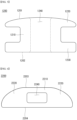
FIG. 3 is a perspective view illustrating theshunt 200 ofFIG. 2 . -
FIG. 4 is a plan view of theshunt 200 ofFIG. 3 . -
FIG. 5 is a plan view illustrating ashunt 1200 according to another embodiment of the present disclosure. -
FIG. 6 is a front view illustrating ashunt 2200 according to another embodiment of the present disclosure. -
FIG. 7 illustrates that aqueous humor within afirst bleb 140 ofFIG. 2 is drained through ashunt 200. -
FIG. 8 illustrates that asecond bleb 170 is formed due to aqueous humor drained through theshunt 200 ofFIG. 7 . -
FIG. 9 illustrates that an additional shunt 200' is mounted in thesecond bleb 170 ofFIG. 8 . -
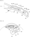
FIG. 10 illustrates that anadditional shunt 200" is mounted in thefirst bleb 140 ofFIG. 8 . - Reference will now be made in detail to embodiments of the disclosure, examples of which are illustrated in the accompanying drawings. Wherever possible, the same reference numbers will be used throughout the drawings to refer to the same or like parts. In general, a suffix such as "module" and "unit" may be used to refer to elements or components. Use of such a suffix herein is merely intended to facilitate description of the present disclosure, and the suffix itself is not intended to give any special meaning or function. The accompanying drawings are used to help easily understand various technical features and it should be understood that embodiments presented herein are not limited by the accompanying drawings. As such, the present disclosure should be construed to extend to any alterations, equivalents and substitutes in addition to those which are particularly set out in the accompanying drawings.
- The terms including an ordinal number such as first, second, or the like may be used to describe various components, but the components are not limited by such terms. The terms are used only for the purpose of distinguishing one component from other components.
- When any component is described as "being connected" or "being coupled" to other component, this should be understood to mean that another component may exist between them, although any component may be directly connected or coupled to the other component. In contrast, when any component is described as "being directly connected" or "being directly coupled" to other component, this should be understood to mean that no component exists between them.
- A singular expression can include a plural expression as long as it does not have an apparently different meaning in context.
- In the present disclosure, terms "include" and "have" should be understood to be intended to designate that illustrated features, numbers, steps, operations, components, parts or combinations thereof are present and not to preclude the existence of one or more different features, numbers, steps, operations, components, parts or combinations thereof, or the possibility of the addition thereof.
- In the drawings, sizes of the components may be exaggerated or reduced for convenience of explanation. For example, the size and the thickness of each component illustrated in the drawings are arbitrarily illustrated for convenience of explanation, and thus the present disclosure is not limited thereto unless specified as such.
- If any embodiment is implementable differently, a specific order of processes may be performed differently from the order described. For example, two consecutively described processes may be performed substantially at the same time, or performed in the order opposite to the described order.
- In the following embodiments, when layers, areas, components, or the like are connected, the following embodiments include both the case where layers, areas, and components are directly connected, and the case where layers, areas, and components are indirectly connected to other layers, areas, and components intervening between them.
-
FIG. 2 illustrates that ashunt 200 according to an embodiment of the present disclosure is mounted in thefirst bleb 140 ofFIG. 1 .FIG. 3 is a perspective view illustrating theshunt 200 ofFIG. 2 . - The
first bleb 140 may be formed around aglaucoma drainage device 150. Thefirst bleb 140 may include aqueous humor drained from ananterior chamber 110 or theglaucoma drainage device 150. Thefirst bleb 140 may be formed in a convex shape protruding from asclera 120. - The
first bleb 140 may include a firstfibrous encapsulation 141 surrounding thefirst bleb 140. The firstfibrous encapsulation 141 may be formed as an encapsulation of thefirst bleb 140 is fibrosed. - The
first bleb 140 may include a firstinternal space 142 formed between the firstfibrous encapsulation 141 and thesclera 120. The aqueous humor may be filled in the firstinternal space 142. - Depending on a location of the
glaucoma drainage device 150 or conditions of a patient, thefirst bleb 140 may convexly protrude on thesclera 120. The firstinternal space 142 may be formed between thesclera 120 and the firstfibrous encapsulation 141. - The
shunt 200 may extend from anend 201 to anotherend 202. For example, theend 201 of theshunt 200 may be a front end of theshunt 200. For example, theother end 202 of theshunt 200 may be a rear end of theshunt 200. A longitudinal direction of theshunt 200 may be parallel to a direction from theend 201 to theother end 202. For example, the longitudinal direction of theshunt 200 may be a front-rear direction. - The
end 201 of theshunt 200 may be directed toward the outside of thefirst bleb 140. Theend 201 of theshunt 200 may be positioned outside the firstfibrous encapsulation 141. Theother end 202 of theshunt 200 may be directed toward the inside of thefirst bleb 140. Theother end 202 of theshunt 200 may be positioned inside the firstfibrous encapsulation 141. The other end of theshunt 200 may be positioned in the firstinternal space 142. - The
shunt 200 may include amain body 210. Themain body 210 may extend in the longitudinal direction of theshunt 200. Themain body 210 may be formed in a rectangular parallelepiped shape. Themain body 210 may be arranged to penetrate the firstfibrous encapsulation 141. A lower surface (lower side inFIG. 3 ) of themain body 210 may be arranged to face thesclera 120. - The
main body 210 may be formed longer than a thickness of the firstfibrous encapsulation 141. Hence, a side of themain body 210 may be located outside the firstfibrous encapsulation 141, and another side of themain body 210 may be located inside the firstfibrous encapsulation 141. A width of themain body 210 may be greater than a height of themain body 210. - The
shunt 200 may include afirst support member 220. Thefirst support member 220 may be connected to the side of themain body 210. Thefirst support member 220 may be located outside thefirst bleb 140. Thefirst support member 220 may be located outside the firstfibrous encapsulation 141. - The
first support members 220 may be respectively formed on opposite sides of themain body 210 facing each other in a width direction of themain body 210. Thefirst support members 220 may extend in the width direction of themain body 210 on the opposite sides of themain body 210. Thefirst support members 220 may extend in a width direction of thefirst bleb 140 on the opposite sides of themain body 210. Thefirst support members 220 may be caught on an outer surface of the firstfibrous encapsulation 141 to prevent theshunt 200 from falling into the inside of the firstfibrous encapsulation 141. The front of themain body 210 may be supported on the outer surface of the firstfibrous encapsulation 141 by thefirst support members 220. - The
first support member 220 may be located between the firstfibrous encapsulation 141 and theconjunctiva 130. Thefirst support member 220 may be in contact with the outer surface of the firstfibrous encapsulation 141. Thefirst support member 220 may be in contact with theconjunctiva 130. - The
shunt 200 may include asecond support member 230. Thesecond support member 230 may be connected to the other side of themain body 210. Thesecond support member 230 may be located inside thefirst bleb 140. Thesecond support member 230 may be located inside the firstfibrous encapsulation 141. - The
second support members 230 may be respectively formed on opposite sides of themain body 210 facing each other in the width direction of themain body 210. Thesecond support members 230 may extend on the opposite sides of themain body 210 in the width direction of themain body 210. Thesecond support members 230 may extend on the opposite sides of themain body 210 in the width direction of thefirst bleb 140. Thesecond support members 230 may be caught on an inner surface of the firstfibrous encapsulation 141 to prevent theshunt 200 from falling into the outside of the firstfibrous encapsulation 141. The rear of themain body 210 may be supported on the inner surface of the firstfibrous encapsulation 141 by thesecond support members 230. - The
second support member 230 may be in contact with the inner surface of the firstfibrous encapsulation 141. Thesecond support member 230 may extend in a direction parallel to the direction in which thefirst support member 220 extends. - A height HS of the
shunt 200 may be less than a height of theglaucoma drainage device 150. In case that the top of theshunt 200 is formed flat, the height of themain body 210, a height of thefirst support member 220, and a height of thesecond support member 230 may be the same as the height HS of theshunt 200. - The
shunt 200 may include aflow path 240 formed in themain body 210. Theflow path 240 may be formed by penetrating themain body 210 in the longitudinal direction. For example, theflow path 240 may be formed by penetrating themain body 210 in the front-rear direction. For example, theflow path 240 may be formed as a rectangular hole. For example, theflow path 240 may be formed as an oval hole. For example, theflow path 240 may be formed as a semi-oval hole. Theflow path 240 may be formed sufficiently wide so that the aqueous humor within thefirst bleb 140 can be drained to the outside of thefirst bleb 140 through theflow path 240. - A width of the
flow path 240 may greater than a height of theflow path 240. The width of theflow path 240 may be formed sufficiently long within a range where the center of theflow path 240 is not pressed by an external force acting on theshunt 200. The external force acting on theshunt 200 may include a force of surrounding tissue of theshunt 200, a force blinking theeyeball 100, or the like. Through the shape of theflow path 240, the height of theflow path 240 can be minimized and a cross-sectional area of theflow path 240 can increase. As a result, the height of themain body 210 in which theflow path 240 is formed can also be minimized, and the aqueous humor in thefirst bleb 140 can be smoothly drained through theflow path 240. - The inside of the
first bleb 140 and the outside of thefirst bleb 140 may be connected by theflow path 240. Hence, the aqueous humor of the firstinternal space 142 can be drained to the outside of thefirst bleb 140. For example, the firstinternal space 142 may be connected to a space formed between thefirst bleb 140 and theconjunctiva 130 by theflow path 240. Because the aqueous humor of the firstinternal space 142 is in a high pressure state, the aqueous humor may be drained to a low pressure side through theflow path 240. For example, the aqueous humor of the firstinternal space 142 may be drained to the space formed between thefirst bleb 140 and theconjunctiva 130. - The
shunt 200 may include aninstallation groove 250 formed by being surrounded by themain body 210, thefirst support member 220, and thesecond support member 230. Both sides of theinstallation groove 250 may be open in a height direction (up-down direction) of theshunt 200. Theinstallation groove 250 may be formed so that the opposite side of theflow path 240 is open in a width direction of theshunt 200. The firstfibrous encapsulation 141 may be accommodated in theinstallation groove 250. Hence, thefirst support member 220 located outside the firstfibrous encapsulation 141 may not enter the firstinternal space 142. As a result, thesecond support member 230 located inside the firstfibrous encapsulation 141 may not fall out of thefirst bleb 140. - Edges of the
shunt 200 may be rounded. The rounding can minimize damage to theconjunctiva 130 caused by the edges of theshunt 200. If theconjunctiva 130 is damaged, fine tissues within theconjunctiva 130 may be stimulated, thereby promoting ulceration or fibrosis. - Edges of the
flow path 240 may be rounded. The rounding can improve an impact strength or a fracture resistance around theflow path 240. - The
shunt 200 may be formed by including a silicone material. Themain body 210, thefirst support member 220, and thesecond support member 230 may be formed by including a silicone material. Hence, the flexibility of theshunt 200 can be improved, and a foreign body sensation caused by theshunt 200 when theeyeball 100 or the eyelid moves can be reduced. In addition, when an impact is applied to theeyeball 100 or the area around theeyeball 100, the risk of theeyeball 100 being damaged by theshunt 200 can be reduced. In addition, because theshunt 200 is easy to be installed and removed, theshunt 200 can be installed and removed with minimum procedures in a short period of time. - The
shunt 200 may be formed by including a sterilized silicone material. For example, theshunt 200 may be formed by including a medical grade implantable silicone material that can be implanted into the human body. For example, theshunt 200 may be formed by including MED-4830 manufactured by Nusil Technology LLC. As a result, the stability of theshunt 200 in the body can be improved, and a rejection reaction to theshunt 200 can be reduced. -
FIG. 4 is a plan view of theshunt 200 ofFIG. 3 . A thickness of thefirst support member 220 is a length of thefirst support member 220 and may be referred to as a first thickness t1. A thickness of thesecond support member 230 is a length of thesecond support member 230 and may be referred to as a second thickness t2. - The first thickness t1 may be less than the second thickness t2. Hene, the foreign body sensation caused by the
first support member 220 located outside thefirst bleb 140 can be reduced. - The second thickness t2 may be thicker than the first thickness t1. Hence, the
second support member 230 located inside thefirst bleb 140 may have a difficulty falling out of the firstfibrous encapsulation 141. If the second thickness t2 is too thin, thesecond support member 230 may easily fold toward theother end 202 of themain body 210. Therefore, thesecond support member 230 may fold and fall out of thefirst bleb 140 due to a pressure inside thefirst bleb 140 or the external force applied to theshunt 200. - To make it difficult for the
second support member 230 to fall out of the firstfibrous encapsulation 141, thesecond support member 230 may sufficiently extend from themain body 210. - In other embodiments, the first thickness t1 may be similar to the second thickness t2. Hene, it can be difficult for the
first support member 220 to enter the inside of the firstfibrous encapsulation 141. In addition, the shape of thefirst support member 220 and the shape of thesecond support member 230 are similar, and thus the inside and the outside of theshunt 200 may be changed and used. -
FIG. 5 is a plan view illustrating ashunt 1200 according to another embodiment of the present disclosure. - A front surface of a
main body 1210 may get closer to a rear surface of themain body 1210 as it goes away from the center of themain body 1210. For example, the front surface of themain body 1210 may be formed in a curved shape. - In addition, a front surface of the
first support member 1220 may get closer to a rear surface of thefirst support member 1220 as it goes away from themain body 1210. For example, the front surface of thefirst support member 1220 may be formed in a curved shape and may be continuously formed by being connected to the front surface of themain body 1210. - The front surface of the
main body 1210 and the front surface of thefirst support member 1220 may be formed in a curved shape which convexly protrudes as they go to the center of theshunt 1200. A front surface of theshunt 1200 may be formed in a convex shape. - As a result, a foreign body sensation caused by the front surface of the
shunt 1200 can be reduced. In addition, damage to the conjunctiva 130 (seeFIG. 2 ) caused by a front side of themain body 1210 and thefirst support member 1220 can be minimized. -
FIG. 6 is a front view illustrating ashunt 2200 according to another embodiment of the present disclosure. - An upper surface of a
first support member 2220 may get closer to the sclera 120 (seeFIG. 2 ) as it goes away from amain body 2210. For example, the upper surface of thefirst support member 2220 may be formed in a curved surface and connected to an upper surface of themain body 2210. A connection part between the upper surface of thefirst support member 2220 and the upper surface of themain body 2210 may be rounded. - An upper surface of a front of the
main body 2210 may get closer to thesclera 120 as it goes away from the center of themain body 2210 in a width direction. For example, the upper surface of themain body 2210 may be formed in a curved surface and may be continuously formed by being connected to the upper surface of thefirst support member 2220. - Because the upper surface of the front of the
main body 2210 and the upper surface of thefirst support member 2220 are positioned close to the conjunctiva 130 (seeFIG. 2 ), damage to the conjunctiva 130 (seeFIG. 2 ) can be minimized by the shapes of themain body 2210 and thefirst support member 2220. In addition, a foreign body sensation caused by themain body 2210 and thefirst support member 2220 can be reduced. - In addition, a second support member (not shown, see '230' of
FIG. 3 ) may be formed in the same or similar manner as thefirst support member 2220. The upper surface of themain body 2210 may be entirely formed in the same or similar manner as the upper surface of the front of themain body 2210. An upper surface of the second support member may be continuously formed by being connected to an upper surface of a rear of themain body 2210. - The second support member may be positioned close to an inner surface of the first bleb 140 (see
FIG. 2 ), and themain body 2210 may penetrate thefirst bleb 140. Therefore, damage to thefirst bleb 140 can be minimized by the shape of the second support member and themain body 2210. - When the
shunt 200 is mounted in thefirst bleb 140 as illustrated inFIG. 2 , the aqueous humor of the firstinternal space 142 may be drained to the outside of thefirst bleb 140 as illustrated inFIG. 7 . For example, the aqueous humor of the firstinternal space 142 may be drained to asubconjunctival space 160 through theshunt 200. A direction in which the aqueous humor of the firstinternal space 142 is drained to the outside of the first bleb 140 (e.g., the subconjunctival space 160) through theshunt 200 may be referred to as a third direction F3. The aqueous humor of theanterior chamber 110 may move through the first direction F1, the second direction F2, and the third direction F3. When the aqueous humor within thefirst bleb 140 is drained, a pressure increase caused by the aqueous humor can be alleviated, and thus a pressure of thefirst bleb 140 and a pressure (intraocular pressure) of the eyeball 100 (seeFIG. 1 ) can be reduced. - When the
shunt 200 is mounted in thefirst bleb 140, theshunt 200 may be mounted as close as possible to a connection part between thefirst bleb 140 and thesclera 120. Hence, the foreign body sensation and damage to theconjunctiva 130 caused by theshunt 200 can be minimized. In addition, when theshunt 200 is mounted in thefirst bleb 140, the upper surface of theshunt 200 may be mounted lower than an upper surface of theglaucoma drainage device 150. Hence, the foreign body sensation and damage to theconjunctiva 130 caused by theshunt 200 can be minimized. - A height of the first
internal space 142 inFIG. 2 may be referred to as a first height H1, and a height of the firstinternal space 142 inFIG. 7 may be referred to as a second height H2. The second height H2 may be lower than the first height H1. When the aqueous humor in thefirst bleb 140 is drained to the outside of thefirst bleb 140 by theshunt 200, the first height H1 may be lowered to become the second height H2. As a result, the pressure in thefirst bleb 140 can be reduced. - If the aqueous humor in the
first bleb 140 continues to flow in the third direction F3, a new bleb, which is asecond bleb 170, may be formed outside theshunt 200, as illustrated inFIG. 8 . The aqueous humor drained to the outside of thefirst bleb 140 may be widely spread by thesecond bleb 170 and absorbed into the blood flow. - As time passes, the
second bleb 170 may be fibrosed and may not smoothly absorb the aqueous humor. Theshunt 200 may be additionally mounted in thefirst bleb 140 or thesecond bleb 170 to drain the aqueous humor within thefirst bleb 140 or thesecond bleb 170. The additionally mountedshunt 200 may be mounted at a different location from the previously mountedshunt 200. -
FIG. 9 illustrates that an additional shunt 200' is mounted in thesecond bleb 170 ofFIG. 8 . The additional shunt 200' may be mounted in thesecond bleb 170. For example, the additional shunt 200' may be mounted in a secondfibrous encapsulation 171 of thesecond bleb 170. - The aqueous humor in the
second bleb 170 may be drained to the outside of thesecond bleb 170 by the additional shunt 200'. For example, the aqueous humor in a secondinternal space 172 may be drained to the space between theconjunctiva 130 and thesclera 120 by the additional shunt 200'. A direction in which the aqueous humor in thesecond bleb 170 is drained to the outside of thesecond bleb 170 by the additional shunt 200' may be referred to as a fourth direction F4. The fourth direction F4 may be a direction parallel to the third direction F3. The aqueous humor in theanterior chamber 110 may move through the first direction F1, the second direction F2, the third direction F3, and the fourth direction F4. - If the aqueous humor in the
second bleb 170 continues to flow in the fourth direction F4, a new bleb, which is athird bleb 180, may be formed outside the additional shunt 200'. The aqueous humor drained from thesecond bleb 170 to thethird bleb 180 may be widely spread by thethird bleb 180 and absorbed into the blood flow. As time passes, thethird bleb 180 may be fibrosed. Further, a thirdfibrous encapsulation 181 may be formed, and the aqueous humor may accumulate in a thirdinternal space 182. -
FIG. 10 illustrates that anadditional shunt 200" is mounted in thefirst bleb 140 ofFIG. 8 . Theadditional shunt 200" may be mounted in thefirst bleb 140. For example, theshunt 200 and theadditional shunt 200" may be arranged such that theglaucoma drainage device 150 are located between theshunt 200 and theadditional shunt 200". For example, theshunt 200 and theadditional shunt 200" may be positioned along the perimeter of the cornea. For example, if theshunt 200 is mounted at the 9 o'clock direction of the first bleb 140 (left side inFIG. 10 ), theadditional shunt 200" may be mounted at the 3 o'clock direction of the first bleb 140 (right side inFIG. 10 ). For example, if theshunt 200 is mounted at the 9 o'clock direction of the first bleb 140 (left side inFIG. 10 ), theadditional shunt 200" may be mounted at the 6 o'clock direction of the first bleb 140 (lower side inFIG. 10 ). - The aqueous humor in the
first bleb 140 may be drained to the outside of thefirst bleb 140 by theadditional shunt 200". For example, the aqueous humor in the firstinternal space 142 may be drained to the space between theconjunctiva 130 and thesclera 120 by theadditional shunt 200". - A direction in which the aqueous humor in the
first bleb 140 is drained to the outside of thefirst bleb 140 by theadditional shunt 200" may be referred to as a fifth direction F5. The fifth direction F5 may form an angle with respect to the third direction F3. For example, the fifth direction F5 may be the opposite direction to the third direction F3. The aqueous humor in theanterior chamber 110 may move through the first direction F1, the second direction F2, and the third direction F3 or may move through the first direction F1, the second direction F2, and the fifth direction F5. - If the aqueous humor in the
first bleb 140 continues to flow in the fifth direction F5, a new bleb, which is a third bleb 180', may be formed outside theadditional shunt 200". The aqueous humor drained from thefirst bleb 140 to the third bleb 180' may be widely spread by the third bleb 180' and absorbed into the blood flow. - The
blebs first bleb 140, thesecond bleb 170, and thethird bleb 180. The plurality ofshunts 200 may be mounted in theblebs - A surgical method of installing the
shunt 200 according to an embodiment of the present disclosure to thefirst bleb 140 formed around theglaucoma drainage device 150 is described below with reference toFIG. 2 . Theshunt 200 can also be applied to a bleb formed by trabeculectomy, in addition to theblebs glaucoma drainage device 150. - A surgical site may be prepared through a general anesthesia process and sterilization process. The surgical site may be exposed using drugs or stay sutures to secure a surgical view.
- After checking the extent of the fibrosed
first bleb 140, a site where theshunt 200 is to be installed may be determined depending on a location of theglaucoma drainage device 150 of a patient. If theglaucoma drainage device 150 is installed on a lateral side of theeyeball 100, an upward site or a downward site of thefirst bleb 140 may be determined as the site where theshunt 200 is to be installed. The site where theshunt 200 is to be installed may be determined as a site as close to thesclera 120 as possible. - The
conjunctiva 130 may be incised to expose thefirst bleb 140. For example, theconjunctiva 130 at the site where theshunt 200 is installed may be held with conjunctival forceps and may be bluntly dissected with Stevens or Westcott tenotomy scissors to expose a part of thefirst bleb 140. Theconjunctiva 130 may be incised while avoiding blood vessels of theconjunctiva 130. However, if it is difficult to avoid the blood vessels of theconjunctiva 130, theconjunctiva 130 may be incised after a hemostatic treatment, such as cauterization, and hemostatic treatment can be applied to any bleeding that occurs during the incision. - A part of the first
fibrous encapsulation 141 of the exposedfirst bleb 140 may be incised or excised to provide a space for installing theshunt 200. For example, a part of the exposed firstfibrous encapsulation 141 may be incised or excised using a blade or a special punch to provide a space for installing theshunt 200. In this instance, the firstfibrous encapsulation 141 may be incised longer than a widthwise length of theshunt 200. - The
shunt 200 may be mounted in an incision site of the firstfibrous encapsulation 141. For example, theshunt 200 may be implanted into the incision site of the firstfibrous encapsulation 141 using forceps and mounted in the firstfibrous encapsulation 141. In this instance, thesecond support member 230 may be made to enter the firstinternal space 142 inside thefirst bleb 140. - If a length of the incision site of the first
fibrous encapsulation 141 is excessively longer than a width of theshunt 200, the incision site of the firstfibrous encapsulation 141 may be sutured using a suture after theshunt 200 is mounted. - After the
shunt 200 is installed, it may be confirmed that the aqueous humor in thefirst bleb 140 is drained to the outside of thefirst bleb 140 through theshunt 200, and theconjunctiva 130 may be sutured using the suture. As described above, because the surgery to install theshunt 200 in the firstfibrous encapsulation 141 is performed minimally invasively, the physical and financial burden on the patient for the surgery can be reduced, and the patient's recovery speed can be accelerated. In addition, because the damage to thefirst bleb 140 is minimized, the possibility of conjunctival ulceration can be reduced. - Some embodiments or other embodiments of the present disclosure described above are not mutually exclusive or distinct from each other. Configurations or functions of some embodiments or other embodiments of the present disclosure described above can be used together or combined with each other.
- It is apparent to those skilled in the art that the present disclosure can be embodied in other specific forms without departing from the spirit and essential features of the present disclosure. Accordingly, the above detailed description should not be construed as limiting in all aspects and should be considered as illustrative. The scope of the present disclosure should be determined by rational interpretation of the appended claims, and all modifications within an equivalent scope of the present disclosure are included in the scope of the present disclosure.
Claims (20)
- A shunt comprising:a main body penetrating a fibrous encapsulation of a bleb formed between a sclera and a conjunctiva; anda flow path penetrating the main body, the flow path draining an aqueous humor within the bleb to an outside of the bleb.
- The shunt of claim 1, further comprising:a first support member connected to a front of the main body and positioned outside the fibrous encapsulation; anda second support member connected to a rear of the main body and positioned inside the fibrous encapsulation,wherein the main body includes a lower surface facing the sclera, andwherein the flow path penetrates the main body from the front to the rear.
- The shunt of claim 1, wherein a width of the main body is greater than a height of the main body.
- The shunt of claim 1, wherein a height of the main body is less than a height of a glaucoma drainage device located inside the bleb.
- The shunt of claim 1, wherein a width of the flow path is greater than a height of the flow path.
- The shunt of claim 2, wherein the front of the main body is supported on an outer surface of the fibrous encapsulation by the first support member, and
wherein the rear of the main body is supported on an inner surface of the fibrous encapsulation by the second support member. - The shunt of claim 2, wherein the first support member extends in a width direction of the main body, and
wherein the second support member extends in the width direction of the main body. - The shunt of claim 7, wherein the fibrous encapsulation is implanted between the first support member and the second support member.
- The shunt of claim 1, wherein the main body is located adjacent to a connection part between the bleb and the sclera.
- The shunt of claim 2, wherein, in a longitudinal direction of the main body, the first support member is thinner than the second support member.
- The shunt of claim 2, wherein, in a longitudinal direction of the main body, a thickness of the first support member is similar to a thickness of the second support member.
- The shunt of claim 2, wherein a front surface of the first support member includes a curved surface which gets closer to a rear surface of the first support member as it goes away from the main body.
- The shunt of claim 2, wherein an upper surface of the first support member and an upper surface of the second support member each include a curved surface which gets closer to the sclera as it goes away from the main body.
- The shunt of claim 13, wherein an upper surface of the main body includes a curved surface which gets closer to the sclera as it goes away from a center of the main body in a width direction, and
wherein the curved surface of the main body is formed continuously with the curved surface of the first support member and the curved surface of the second support member. - The shunt of claim 2, wherein the main body, the first support member, and the second support member each include a rounded edge.
- The shunt of claim 1, wherein the flow path includes a rounded edge.
- The shunt of claim 1, further comprising a first shunt and a second shunt respectively mounted at different locations of the fibrous encapsulation.
- The shunt of claim 17, wherein the first shunt and the second shunt are arranged such that a glaucoma drainage device inside the bleb is located between the first shunt and the second shunt.
- The shunt of claim 18, wherein the first shunt and the second shunt are arranged along a perimeter of a cornea.
- The shunt of claim 1, further comprising:a first shunt mounted in the fibrous encapsulation of the bleb; anda second shunt formed by the aqueous humor drained to the outside of the bleb, the second shunt being mounted in a fibrous encapsulation of a second bleb connected to the bleb.
Applications Claiming Priority (2)
| Application Number | Priority Date | Filing Date | Title |
|---|---|---|---|
| KR1020220082539A KR102828111B1 (en) | 2022-07-05 | 2022-07-05 | Shunt for fibrous encapsulation in glaucoma patients |
| PCT/KR2023/009331 WO2024010310A1 (en) | 2022-07-05 | 2023-07-03 | Shunt for fibrous encapsulation in glaucoma patients |
Publications (2)
| Publication Number | Publication Date |
|---|---|
| EP4552623A1 true EP4552623A1 (en) | 2025-05-14 |
| EP4552623A4 EP4552623A4 (en) | 2026-03-11 |
Family
ID=89453759
Family Applications (1)
| Application Number | Title | Priority Date | Filing Date |
|---|---|---|---|
| EP23835776.8A Pending EP4552623A4 (en) | 2022-07-05 | 2023-07-03 | SHUNT FOR FIBER CAPSULE IN GLAUCOMA PATIENTS |
Country Status (3)
| Country | Link |
|---|---|
| EP (1) | EP4552623A4 (en) |
| KR (1) | KR102828111B1 (en) |
| WO (1) | WO2024010310A1 (en) |
Family Cites Families (12)
| Publication number | Priority date | Publication date | Assignee | Title |
|---|---|---|---|---|
| US5300020A (en) * | 1991-05-31 | 1994-04-05 | Medflex Corporation | Surgically implantable device for glaucoma relief |
| JP4290915B2 (en) * | 2000-01-12 | 2009-07-08 | ベクトン・ディキンソン・アンド・カンパニー | System and method for reducing intraocular pressure |
| US20060200113A1 (en) * | 2002-03-07 | 2006-09-07 | David Haffner | Liquid jet for glaucoma treatment |
| KR20070035529A (en) | 2004-06-01 | 2007-03-30 | 벡톤 디킨슨 앤드 컴퍼니 | Ophthalmic implants and methods of manufacturing the same and methods of using the same |
| US9381112B1 (en) * | 2011-10-06 | 2016-07-05 | William Eric Sponsell | Bleb drainage device, ophthalmological product and methods |
| CA2936659A1 (en) * | 2014-01-14 | 2015-07-23 | University Of Utah Research Fundation | Schlemm's canal stent-sieve |
| KR101812246B1 (en) * | 2016-07-18 | 2018-01-30 | 인제대학교 산학협력단 | Glaucoma drainage device for intraocular pressure control |
| US20200229978A1 (en) * | 2017-08-11 | 2020-07-23 | University Of Florida Research Foundation, Incorporated | Enhanced drainage of failed glaucoma drainage device (gdd) |
| EP3706653A4 (en) * | 2017-11-08 | 2021-07-14 | Aquesys, Inc. | Manually adjustable intraocular flow regulation |
| CN109223302B (en) * | 2018-11-21 | 2020-12-25 | 中国人民解放军总医院 | Aqueous humor drainage device and manufacturing method thereof |
| KR20200118291A (en) | 2019-04-04 | 2020-10-15 | 타이완 파이버 옵틱스 인코포레이티드 | Shunt stent for eye drainage |
| KR102388341B1 (en) | 2020-06-26 | 2022-04-19 | 가톨릭대학교 산학협력단 | A drainage device for pipe capable controlling diameter |
-
2022
- 2022-07-05 KR KR1020220082539A patent/KR102828111B1/en active Active
-
2023
- 2023-07-03 WO PCT/KR2023/009331 patent/WO2024010310A1/en not_active Ceased
- 2023-07-03 EP EP23835776.8A patent/EP4552623A4/en active Pending
Also Published As
| Publication number | Publication date |
|---|---|
| KR20240005440A (en) | 2024-01-12 |
| KR102828111B1 (en) | 2025-07-01 |
| WO2024010310A1 (en) | 2024-01-11 |
| EP4552623A4 (en) | 2026-03-11 |
Similar Documents
| Publication | Publication Date | Title |
|---|---|---|
| US4787885A (en) | Hydrogel seton | |
| US11980574B2 (en) | Ocular device for treating glaucoma and related minimally invasive glaucoma surgery method | |
| US12514750B2 (en) | Method and apparatus for implant in the conventional aqueous humor outflow pathway of a mammalian eye | |
| US4634418A (en) | Hydrogel seton | |
| US9808374B2 (en) | Ocular drainage device and method of manufacturing thereof | |
| EP3666236B1 (en) | Glaucoma implant device | |
| RU2749066C2 (en) | Apparatus and method of extracting aqueous humour | |
| JP2002521145A (en) | Sutureless implantable devices and methods for treating glaucoma | |
| RU2721299C2 (en) | Interposition ophthalmic implant | |
| US20260076829A1 (en) | Shunt And Method For Treating Glaucoma | |
| US20250248846A1 (en) | Ophtalmological interposition implant with engagement protusion | |
| KR102828111B1 (en) | Shunt for fibrous encapsulation in glaucoma patients | |
| US20230079304A1 (en) | Slotted ocular lens | |
| KR102791995B1 (en) | Drainage device for intraocular pressure control with flow control unit | |
| RU2802556C1 (en) | Method of preventing scarring of a filtration cushion during anti-glaucomatous surgeries with ahmed valve type drainage implantation | |
| US20240081973A1 (en) | Method for positioning an interpositional ophthalmological implant using ab-interno approach | |
| US20250073070A1 (en) | An ocular implant for the treatment of glaucoma | |
| KR20260009516A (en) | Surgical method for insertion of implant device for eye disease | |
| EP3468513A1 (en) | Devices, systems, and methods for trabecular meshwork extension | |
| HK40010130B (en) | Drainage device for draining the aqueous humour of the eyeball | |
| HK40010130A (en) | Drainage device for draining the aqueous humour of the eyeball |
Legal Events
| Date | Code | Title | Description |
|---|---|---|---|
| STAA | Information on the status of an ep patent application or granted ep patent |
Free format text: STATUS: THE INTERNATIONAL PUBLICATION HAS BEEN MADE |
|
| PUAI | Public reference made under article 153(3) epc to a published international application that has entered the european phase |
Free format text: ORIGINAL CODE: 0009012 |
|
| STAA | Information on the status of an ep patent application or granted ep patent |
Free format text: STATUS: REQUEST FOR EXAMINATION WAS MADE |
|
| 17P | Request for examination filed |
Effective date: 20250124 |
|
| AK | Designated contracting states |
Kind code of ref document: A1 Designated state(s): AL AT BE BG CH CY CZ DE DK EE ES FI FR GB GR HR HU IE IS IT LI LT LU LV MC ME MK MT NL NO PL PT RO RS SE SI SK SM TR |
|
| DAV | Request for validation of the european patent (deleted) | ||
| DAX | Request for extension of the european patent (deleted) | ||
| A4 | Supplementary search report drawn up and despatched |
Effective date: 20260205 |
|
| RIC1 | Information provided on ipc code assigned before grant |
Ipc: A61F 9/007 20060101AFI20260130BHEP |