EP4552580A2 - Chirurgische führung mit zusammengesetzter ultraschallbildgebung - Google Patents
Chirurgische führung mit zusammengesetzter ultraschallbildgebung Download PDFInfo
- Publication number
- EP4552580A2 EP4552580A2 EP24211131.8A EP24211131A EP4552580A2 EP 4552580 A2 EP4552580 A2 EP 4552580A2 EP 24211131 A EP24211131 A EP 24211131A EP 4552580 A2 EP4552580 A2 EP 4552580A2
- Authority
- EP
- European Patent Office
- Prior art keywords
- ultrasound
- field
- image
- rendering
- neural
- Prior art date
- Legal status (The legal status is an assumption and is not a legal conclusion. Google has not performed a legal analysis and makes no representation as to the accuracy of the status listed.)
- Pending
Links
Images





Classifications
-
- A—HUMAN NECESSITIES
- A61—MEDICAL OR VETERINARY SCIENCE; HYGIENE
- A61B—DIAGNOSIS; SURGERY; IDENTIFICATION
- A61B34/00—Computer-aided surgery; Manipulators or robots specially adapted for use in surgery
- A61B34/20—Surgical navigation systems; Devices for tracking or guiding surgical instruments, e.g. for frameless stereotaxis
-
- A—HUMAN NECESSITIES
- A61—MEDICAL OR VETERINARY SCIENCE; HYGIENE
- A61B—DIAGNOSIS; SURGERY; IDENTIFICATION
- A61B8/00—Diagnosis using ultrasonic, sonic or infrasonic waves
- A61B8/42—Details of probe positioning or probe attachment to the patient
- A61B8/4245—Details of probe positioning or probe attachment to the patient involving determining the position of the probe, e.g. with respect to an external reference frame or to the patient
- A61B8/4254—Details of probe positioning or probe attachment to the patient involving determining the position of the probe, e.g. with respect to an external reference frame or to the patient using sensors mounted on the probe
-
- A—HUMAN NECESSITIES
- A61—MEDICAL OR VETERINARY SCIENCE; HYGIENE
- A61B—DIAGNOSIS; SURGERY; IDENTIFICATION
- A61B8/00—Diagnosis using ultrasonic, sonic or infrasonic waves
- A61B8/46—Ultrasonic, sonic or infrasonic diagnostic devices with special arrangements for interfacing with the operator or the patient
- A61B8/461—Displaying means of special interest
- A61B8/463—Displaying means of special interest characterised by displaying multiple images or images and diagnostic data on one display
-
- A—HUMAN NECESSITIES
- A61—MEDICAL OR VETERINARY SCIENCE; HYGIENE
- A61B—DIAGNOSIS; SURGERY; IDENTIFICATION
- A61B8/00—Diagnosis using ultrasonic, sonic or infrasonic waves
- A61B8/46—Ultrasonic, sonic or infrasonic diagnostic devices with special arrangements for interfacing with the operator or the patient
- A61B8/461—Displaying means of special interest
- A61B8/466—Displaying means of special interest adapted to display 3D data
-
- A—HUMAN NECESSITIES
- A61—MEDICAL OR VETERINARY SCIENCE; HYGIENE
- A61B—DIAGNOSIS; SURGERY; IDENTIFICATION
- A61B8/00—Diagnosis using ultrasonic, sonic or infrasonic waves
- A61B8/48—Diagnostic techniques
- A61B8/483—Diagnostic techniques involving the acquisition of a 3D volume of data
-
- A—HUMAN NECESSITIES
- A61—MEDICAL OR VETERINARY SCIENCE; HYGIENE
- A61B—DIAGNOSIS; SURGERY; IDENTIFICATION
- A61B8/00—Diagnosis using ultrasonic, sonic or infrasonic waves
- A61B8/52—Devices using data or image processing specially adapted for diagnosis using ultrasonic, sonic or infrasonic waves
- A61B8/5215—Devices using data or image processing specially adapted for diagnosis using ultrasonic, sonic or infrasonic waves involving processing of medical diagnostic data
-
- A—HUMAN NECESSITIES
- A61—MEDICAL OR VETERINARY SCIENCE; HYGIENE
- A61B—DIAGNOSIS; SURGERY; IDENTIFICATION
- A61B8/00—Diagnosis using ultrasonic, sonic or infrasonic waves
- A61B8/52—Devices using data or image processing specially adapted for diagnosis using ultrasonic, sonic or infrasonic waves
- A61B8/5215—Devices using data or image processing specially adapted for diagnosis using ultrasonic, sonic or infrasonic waves involving processing of medical diagnostic data
- A61B8/5238—Devices using data or image processing specially adapted for diagnosis using ultrasonic, sonic or infrasonic waves involving processing of medical diagnostic data for combining image data of patient, e.g. merging several images from different acquisition modes into one image
- A61B8/5246—Devices using data or image processing specially adapted for diagnosis using ultrasonic, sonic or infrasonic waves involving processing of medical diagnostic data for combining image data of patient, e.g. merging several images from different acquisition modes into one image combining images from the same or different imaging techniques, e.g. color Doppler and B-mode
- A61B8/5253—Devices using data or image processing specially adapted for diagnosis using ultrasonic, sonic or infrasonic waves involving processing of medical diagnostic data for combining image data of patient, e.g. merging several images from different acquisition modes into one image combining images from the same or different imaging techniques, e.g. color Doppler and B-mode combining overlapping images, e.g. spatial compounding
-
- A—HUMAN NECESSITIES
- A61—MEDICAL OR VETERINARY SCIENCE; HYGIENE
- A61B—DIAGNOSIS; SURGERY; IDENTIFICATION
- A61B8/00—Diagnosis using ultrasonic, sonic or infrasonic waves
- A61B8/52—Devices using data or image processing specially adapted for diagnosis using ultrasonic, sonic or infrasonic waves
- A61B8/5215—Devices using data or image processing specially adapted for diagnosis using ultrasonic, sonic or infrasonic waves involving processing of medical diagnostic data
- A61B8/5238—Devices using data or image processing specially adapted for diagnosis using ultrasonic, sonic or infrasonic waves involving processing of medical diagnostic data for combining image data of patient, e.g. merging several images from different acquisition modes into one image
- A61B8/5261—Devices using data or image processing specially adapted for diagnosis using ultrasonic, sonic or infrasonic waves involving processing of medical diagnostic data for combining image data of patient, e.g. merging several images from different acquisition modes into one image combining images from different diagnostic modalities, e.g. ultrasound and X-ray
-
- A—HUMAN NECESSITIES
- A61—MEDICAL OR VETERINARY SCIENCE; HYGIENE
- A61B—DIAGNOSIS; SURGERY; IDENTIFICATION
- A61B90/00—Instruments, implements or accessories specially adapted for surgery or diagnosis and not covered by any of the groups A61B1/00 - A61B50/00, e.g. for luxation treatment or for protecting wound edges
- A61B90/36—Image-producing devices or illumination devices not otherwise provided for
- A61B90/37—Surgical systems with images on a monitor during operation
-
- G—PHYSICS
- G01—MEASURING; TESTING
- G01S—RADIO DIRECTION-FINDING; RADIO NAVIGATION; DETERMINING DISTANCE OR VELOCITY BY USE OF RADIO WAVES; LOCATING OR PRESENCE-DETECTING BY USE OF THE REFLECTION OR RERADIATION OF RADIO WAVES; ANALOGOUS ARRANGEMENTS USING OTHER WAVES
- G01S15/00—Systems using the reflection or reradiation of acoustic waves, e.g. sonar systems
- G01S15/88—Sonar systems specially adapted for specific applications
- G01S15/89—Sonar systems specially adapted for specific applications for mapping or imaging
- G01S15/8906—Short-range imaging systems; Acoustic microscope systems using pulse-echo techniques
- G01S15/8934—Short-range imaging systems; Acoustic microscope systems using pulse-echo techniques using a dynamic transducer configuration
- G01S15/8936—Short-range imaging systems; Acoustic microscope systems using pulse-echo techniques using a dynamic transducer configuration using transducers mounted for mechanical movement in three dimensions
-
- G—PHYSICS
- G06—COMPUTING OR CALCULATING; COUNTING
- G06T—IMAGE DATA PROCESSING OR GENERATION, IN GENERAL
- G06T15/00—Three-dimensional [3D] image rendering
- G06T15/08—Volume rendering
-
- G—PHYSICS
- G06—COMPUTING OR CALCULATING; COUNTING
- G06T—IMAGE DATA PROCESSING OR GENERATION, IN GENERAL
- G06T7/00—Image analysis
- G06T7/10—Segmentation; Edge detection
-
- A—HUMAN NECESSITIES
- A61—MEDICAL OR VETERINARY SCIENCE; HYGIENE
- A61B—DIAGNOSIS; SURGERY; IDENTIFICATION
- A61B34/00—Computer-aided surgery; Manipulators or robots specially adapted for use in surgery
- A61B34/20—Surgical navigation systems; Devices for tracking or guiding surgical instruments, e.g. for frameless stereotaxis
- A61B2034/2046—Tracking techniques
- A61B2034/2063—Acoustic tracking systems, e.g. using ultrasound
-
- A—HUMAN NECESSITIES
- A61—MEDICAL OR VETERINARY SCIENCE; HYGIENE
- A61B—DIAGNOSIS; SURGERY; IDENTIFICATION
- A61B90/00—Instruments, implements or accessories specially adapted for surgery or diagnosis and not covered by any of the groups A61B1/00 - A61B50/00, e.g. for luxation treatment or for protecting wound edges
- A61B90/36—Image-producing devices or illumination devices not otherwise provided for
- A61B90/37—Surgical systems with images on a monitor during operation
- A61B2090/378—Surgical systems with images on a monitor during operation using ultrasound
-
- A—HUMAN NECESSITIES
- A61—MEDICAL OR VETERINARY SCIENCE; HYGIENE
- A61B—DIAGNOSIS; SURGERY; IDENTIFICATION
- A61B8/00—Diagnosis using ultrasonic, sonic or infrasonic waves
- A61B8/08—Clinical applications
-
- A—HUMAN NECESSITIES
- A61—MEDICAL OR VETERINARY SCIENCE; HYGIENE
- A61B—DIAGNOSIS; SURGERY; IDENTIFICATION
- A61B8/00—Diagnosis using ultrasonic, sonic or infrasonic waves
- A61B8/12—Diagnosis using ultrasonic, sonic or infrasonic waves in body cavities or body tracts, e.g. by using catheters
-
- A—HUMAN NECESSITIES
- A61—MEDICAL OR VETERINARY SCIENCE; HYGIENE
- A61B—DIAGNOSIS; SURGERY; IDENTIFICATION
- A61B8/00—Diagnosis using ultrasonic, sonic or infrasonic waves
- A61B8/42—Details of probe positioning or probe attachment to the patient
- A61B8/4272—Details of probe positioning or probe attachment to the patient involving the acoustic interface between the transducer and the tissue
- A61B8/429—Details of probe positioning or probe attachment to the patient involving the acoustic interface between the transducer and the tissue characterised by determining or monitoring the contact between the transducer and the tissue
-
- A—HUMAN NECESSITIES
- A61—MEDICAL OR VETERINARY SCIENCE; HYGIENE
- A61B—DIAGNOSIS; SURGERY; IDENTIFICATION
- A61B8/00—Diagnosis using ultrasonic, sonic or infrasonic waves
- A61B8/44—Constructional features of the ultrasonic, sonic or infrasonic diagnostic device
- A61B8/4427—Device being portable or laptop-like
-
- A—HUMAN NECESSITIES
- A61—MEDICAL OR VETERINARY SCIENCE; HYGIENE
- A61B—DIAGNOSIS; SURGERY; IDENTIFICATION
- A61B8/00—Diagnosis using ultrasonic, sonic or infrasonic waves
- A61B8/46—Ultrasonic, sonic or infrasonic diagnostic devices with special arrangements for interfacing with the operator or the patient
- A61B8/467—Ultrasonic, sonic or infrasonic diagnostic devices with special arrangements for interfacing with the operator or the patient characterised by special input means
- A61B8/468—Ultrasonic, sonic or infrasonic diagnostic devices with special arrangements for interfacing with the operator or the patient characterised by special input means allowing annotation or message recording
-
- G—PHYSICS
- G01—MEASURING; TESTING
- G01S—RADIO DIRECTION-FINDING; RADIO NAVIGATION; DETERMINING DISTANCE OR VELOCITY BY USE OF RADIO WAVES; LOCATING OR PRESENCE-DETECTING BY USE OF THE REFLECTION OR RERADIATION OF RADIO WAVES; ANALOGOUS ARRANGEMENTS USING OTHER WAVES
- G01S15/00—Systems using the reflection or reradiation of acoustic waves, e.g. sonar systems
- G01S15/88—Sonar systems specially adapted for specific applications
- G01S15/89—Sonar systems specially adapted for specific applications for mapping or imaging
- G01S15/8906—Short-range imaging systems; Acoustic microscope systems using pulse-echo techniques
- G01S15/8993—Three dimensional imaging systems
-
- G—PHYSICS
- G06—COMPUTING OR CALCULATING; COUNTING
- G06T—IMAGE DATA PROCESSING OR GENERATION, IN GENERAL
- G06T2207/00—Indexing scheme for image analysis or image enhancement
- G06T2207/10—Image acquisition modality
- G06T2207/10132—Ultrasound image
-
- G—PHYSICS
- G06—COMPUTING OR CALCULATING; COUNTING
- G06T—IMAGE DATA PROCESSING OR GENERATION, IN GENERAL
- G06T2207/00—Indexing scheme for image analysis or image enhancement
- G06T2207/20—Special algorithmic details
- G06T2207/20081—Training; Learning
-
- G—PHYSICS
- G06—COMPUTING OR CALCULATING; COUNTING
- G06T—IMAGE DATA PROCESSING OR GENERATION, IN GENERAL
- G06T2207/00—Indexing scheme for image analysis or image enhancement
- G06T2207/20—Special algorithmic details
- G06T2207/20084—Artificial neural networks [ANN]
-
- G—PHYSICS
- G06—COMPUTING OR CALCULATING; COUNTING
- G06T—IMAGE DATA PROCESSING OR GENERATION, IN GENERAL
- G06T2207/00—Indexing scheme for image analysis or image enhancement
- G06T2207/30—Subject of image; Context of image processing
- G06T2207/30004—Biomedical image processing
-
- G—PHYSICS
- G06—COMPUTING OR CALCULATING; COUNTING
- G06T—IMAGE DATA PROCESSING OR GENERATION, IN GENERAL
- G06T2210/00—Indexing scheme for image generation or computer graphics
- G06T2210/41—Medical
Definitions
- Three-dimensional (3D) ultrasound is beneficial for more complete visualization of the organs and internal structures (e.g., vessel trees in the liver), however the performance of the traditional approaches for compounding 2D ultrasound into 3D volumes do not scale well to real intra-operative imaging, resulting in artifacts in rendering and operator confusion for image guidance. Furthermore, since intraoperative ultrasound introduces volumetric deformations to the organs due to the required pressure from the ultrasound probe, it can be challenging to provide real-time synchronized views with pre-operative imaging and planning data.
- Deformable or non-rigid registration between imaging modalities is used in a variety of clinical applications.
- Manual segmentation of the prostate gland in both pre-operative computed tomography (CT) and ultrasound, slice by slice, may be used for registration, but this does not provide for real-time performance and is subject to segmentation variability.
- Deep learning-based approaches achieve real-time performance only for 2D ultrasound to 3D CT registration.
- segmented volume data is converted to surfaces (meshes), and deformation physics is simulated on the mesh data.
- a synthetic ultrasound image is generated from the meshes to produce a deformed ultrasound dataset for use in surgical simulators. This approach requires segmentation and deformation of the ultrasound data, which does not provide for image guidance from pre-operative imaging.
- a neural field uses both probe tracking and ultrasound imaging to compound the ultrasound data into three-dimensions with alignment of the component fields of view. Accurate compounding is provided, and the compounding may operate in real-time.
- modeling e.g., the neural field
- the 3D deformation field may be applied in rendering rather than to the pre-operative volume dataset. This 3D deformation may be used in real-time, allowing for synchronized 3D ultrasound and 3D pre-operative imaging.
- a method for surgical guidance with compounded ultrasound imaging by an ultrasound system.
- the ultrasound system scans tissue of a patient, resulting in two-dimensional (2D) representations. Positions of the 2D representations are tracked.
- the 2D representations are compounded by input of the positions and 2D representations to a neural field.
- the neural field trained with a joint optimization of poses and parameters of the neural field.
- the compounding provides a 3D representation of the patient.
- a first image is rendered from the 3D representation and displayed.
- a medical system for ultrasound compounding.
- An ultrasound probe tracker is configured to track an ultrasound probe during acquisition of ultrasound data.
- a memory is configured to store a machine-learned neural network formed as a neural field.
- An image processor is configured to compound the ultrasound data into a volume representation using the neural field.
- the ultrasound data as compounded has refined positional information from the ultrasound probe tracker.
- a display is configured to display an image from the volume representation.
- a method for surgical guidance with compounded ultrasound imaging by an ultrasound system.
- the ultrasound system scans tissue of a patient, resulting in 2D representations. Pressures corresponding to the 2D representations are tracked.
- a model generates a 3D deformation field from the pressures and the 2D representations. In real-time with the scanning, a pre-operative image is rendered using the 3D deformation field and displayed.
- the third aspect can be considered an application of the first aspect.
- the medical system of the second aspect may be implemented to carry out the methods or parts of the methods of the first and/or third aspect, e.g. as defined in the claims.
- surgical image guidance with neural 3D compounded ultrasound improves the anatomy field of view during interventional procedures compared to 2D ultrasound imaging.
- synchronized viewing of 3D compounded ultrasound and pre-operative (e.g., CT planning) data is provided in real-time, such as based on real-time deformable volume rendering.
- the approaches may be used together, such as the neural field for compounding providing the 3D deformation used to deform the pre-operative imaging to reflect the current state of the tissue during surgery.
- the approaches are described for laparoscopy in the liver.
- liver procedure guidance is provided with deformation-aware ultrasound compounding and visualization.
- the approaches or combination of approaches may be used in other interventions (e.g., open surgery or minimally invasive surgery) and/or for other organs (e.g., kidney).
- 3D tissue deformation is modeled during the intra-operative compounding of 2D ultrasound images.
- the resulting deformation field improves the alignment of the pre-operative image (e.g., CT volume data) to the ultrasound for real-time image guidance during surgical procedures.
- the model-based deformation from the ultrasound compounding algorithm is leveraged to produce a 3D deformation field, which may be applied directly during volume rendering from pre-operative data.
- Techniques for direct visualization of the deformation displacement and time-based visualization of tissue changes are provided.
- the continuously updated deformation field is applied to real-time volume and surface visualization.
- an end-to-end system enables rendering of deformed pre-operative datasets based on ultrasound captured during the procedures in real-time, allowing use during surgery.
- the architecture provides for a real-time system from ultrasound compounding to rendering of deformed data with 128x128x128 volume compounding update rate at 10Hz and rendering update rate at 60Hz.
- a neural field models the 3D scene.
- a coordinate-based neural network is used in structure reconstruction and/or visualization rather than explicitly rendering primitives.
- the weights in the neural network implicitly represent the voxel data.
- Ultrasound compounding and anatomical structure reconstruction is based on a neural field.
- the neural network is initialized from 2D ultrasound slices using a meta-learning technique.
- the neural network is trained based on input of poses (e.g., tracked orientation) to refine the physical probe tracking data jointly with the compounding of 2D ultrasound data into a 3D volume dataset. Joint optimization of the image poses and network weights is used to refine the neural field representation.
- Structure visualization may be based on neural signed distance fields from the neural field.
- the neural field may learn a 3D signed distance function directly from 2D labeling or segmentation of 2D ultrasound images rather than using 3D segmentation.
- the deformation field is learned during training.
- the neural field is trained to output the deformation field as well as or instead of 3D compounding the ultrasound data.
- the deformation field is learned directly during training, e.g., by incorporating differentiable deformable volume rendering.
- view optimization is based on differentiable direct volume rendering.
- Differentiable rendering models the explicit relationship between rendering parameters and resulting images in traditional image synthesis.
- Image-space derivatives are obtained with respect to the rendering parameters, which may be used in a variety of gradient-based optimization methods to solve inverse rendering problems or to compute the loss for training machine learning models directly in the space of rendered images.
- Figure 1 is directed to compounding for ultrasound imaging. Results from scanning a volume are compounded together based of field of view position during the scanning to form a volume representation.
- Figure 5 is directed to generating a deformation field so that a pre-operative volume dataset is rendered in a way reflecting, at least partially, the effect of pressure from the transducer on the organ of interest.
- a model is used to deform, such as the model used to compound.
- Figure 1 is a flow chart diagram of one implementation of a method for surgical guidance with compounded ultrasound imaging by an ultrasound system.
- a neural field compounds in response to input of ultrasound data and probe or field of view tracking information.
- the neural field By machine training the neural field with joint optimization of the parameters of the neural field and probe or field of view position, the neural field accurately refines the position information and fills in missing information.
- the neural field representing the 3D scene is trained during image acquisition.
- the network is initialized at the beginning of the first ultrasound probe sweep.
- the network may be pre-trained with procedure-specific and/or patient-specific data to speed up the training.
- the method of Figure 1 is performed by a medical system, such as the medical scanner, ultrasound system, or medical system of Figure 8 or another medical system.
- a medical system such as the medical scanner, ultrasound system, or medical system of Figure 8 or another medical system.
- an ultrasound scanner acquires ultrasound data using a probe (transducer).
- a sensor and/or image processor tracks the probe or field of view.
- the image processor compounds (e.g., aligns and assembles) the ultrasound data from scanning at different times.
- the image processor and/or a graphics processing unit render an image from the compounded ultrasound data.
- a display displays the image.
- Other devices may perform any of the acts of Figure 1 .
- the method is performed in the order shown (e.g., top to bottom or numerical), but other orders may be used.
- compounding in act 110 may occur interleaved with or between repetitions of acts 100 and 102. Acts 100 and 102 may be performed simultaneously.
- acts 120 and 130 are not performed, such as where the compounding generates a deformation field used on pre-operative data without rendering and display for ultrasound data.
- acts for configuring the scanning, scanning by another modality (e.g., CT or magnetic resonance (MR)) and/or use of output (e.g., measurement) are performed.
- an ultrasound system scans tissue of a patient.
- the patient is scanned.
- the scanning results in multiple 2D representations, such as images formatted in a display domain (e.g., scan converted) or detected ultrasound data formatted in a scan domain rather than the display domain.
- the 2D representations are acquired from memory or transfer over a computer network.
- the 2D representations represent any part of the patient, such as representing an organ, head, or torso of the patient.
- the 2D representations are from scanning a liver of the patient.
- Figure 2 illustrates an example.
- a probe 202 is positioned against an organ (e.g., liver) during surgery.
- a 2D scan is performed, resulting in a 2D image 210.
- Image 220 shows this image as a slab in a different orientation.
- Different 2D representations represent a field of view at different positions within the organ of interest.
- the transducer probe is translated, rocked, and/or rotated as a sequence of 2D representations are acquired.
- a volume of the organ is scanned, resulting in multiple 2D representations.
- the probe 202 is translated without rotation or with little rotation along the organ.
- the image 230 is acquired.
- a collection of such images from different probe positions and/or fields of view within the organ are aligned and assembled (i.e., compounded) to form a volume representation 240.
- Figure 2 shows intra-operative scanning or scanning during open surgery.
- the probe 202 is placed on the skin of the patient to scan internal organs, or the probe is scanned from within the body (e.g., transesophageal or intracardiac echocardiography).
- a matrix array is used to directly scan a volume of the patient with little or no intended movement of the probe.
- the scanning occurs while moving the transducer probe relative to the patient to scan the volume.
- the probe 202 is pressed against and may move along the tissue. This distorts or deforms the tissue, as well as adjacent tissues subjected to the pressure.
- the 2D representations resulting from the scanning are ultrasound data or information derived therefrom.
- different sample locations from scanning or pixel locations in imaging represent ultrasound intensity (e.g., B-mode information).
- Doppler e.g., velocity, variance, and/or power
- ultrasound echoes may be provided instead or as well.
- the ultrasound data is used to segment.
- the 2D representations are segmented to identify locations corresponding to anatomy or objects of interest.
- the locations or data are labeled, such as identifying vessels and/or tumors in the liver.
- the segmentation identifies a border and/or area corresponding to the object.
- the pixels or scan locations corresponding to the object are identified as the segmentation.
- the segmentation is performed using any process or function, such as intensity thresholding with low pass filtering.
- full width, half maximum (FWHM) or intensity thresholding with various standard deviations is used to segment.
- FWHM full width, half maximum
- a user e.g., radiologist
- image processor manually segments.
- a machine-learned model such as an encoder-decoder-based neural network, outputs the segmentation or segmentations in response to input of the 2D representation.
- An image-to-image, U-Net, or encoder-decoder network trained to output the segmentation in response to input of the spatial 2D representation may be applied.
- the machine-trained model (segmentor) generates values for features in hidden layers in response to input of the medical image and uses the values of the features to output the segmentation.
- act 102 the positions of the probe and/or field of view during the scanning is tracked.
- the positions of the 2D representations relative to each other and/or another reference are determined.
- the probe or field of view is tracked in 3D sp ace.
- the image processor compounds the 2D representations into a 3D representation.
- the 2D representations are aligned and assembled (e.g., stacked) to form the 3D representation.
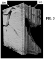
- Figure 3 shows an example of the 2D representations as aligned from the tracking data. Multiple slices or 2D representations 310 are stacked to form the 3D representation 300.
- the 3D representation may have gaps or irregularity due to the variance in speed of probe translation and/or pressure.
- the irregularity may result from or be made worse from inaccuracies in probe tracking.
- the image processor applies a neural field for compounding.
- the tracked positions from act 102 and the 2D representations from act 100 are input the neural field.
- the neural field is a neural network arranged or with an architecture that is coordinate based, such as a 128x128x128 voxel-based arrangement of the neural network.
- Different nodes e.g., weights or activation functions
- the network architecture may use any positional encoding or activation functions that allow the network to fit high frequency signals, e.g., sinusoidal (e.g., SIREN), multiresolution hash or another positional encoding.
- the coordinate domain may be discretized using irregular or hierarchical grids to handle the varying complexity of the volume data due to the sparse acquisition.
- Other neural networks or machine learning models may be used to refine the position and/or compound. For example, an encoder or transformer outputs position in response to input of the position and 2D representation or positions and 2D representations.
- the machine learning model arrangement (architecture) is defined. Any now known or later developed machine-learned model may be used. For example, an image-to-image network, U-Net, DenseNet, ResNet, or encoder-decoder network is used. Down sampling layers, convolutional layers, pooling layers, dropout layers, skip connections, up sampling layers, and/or other neural network layers may be used.
- the coordinate-based neural field is used in one implementation. Any architecture that receives image (spatial) information to output spatial (e.g., image) information may be used.
- the definition is by configuration or programming of the learning. The number of layers or units, type of learning, and other characteristics of the model are controlled by the programmer or user.
- the neural field is then trained to minimize the difference between the intensities in the training images and intensities produced by differentiable volume rendering with the attenuation, reflectance, scattering, etc. fields.
- a photometric loss function is used, but compounding can use a number of metrics to compare the training data images to the images synthesized from the neural fields, e.g., structural similarity index (SSIM).
- SSIM structural similarity index
- the neural field can be used instead of voxel data in the algorithms of the visualization system (e.g., used for rendering).
- the neural field compounds for that scan or surgery of the patient.
- the neural field may operate quickly to compound, allowing generation of the 3D representation in real-time.
- the neural field, neural network, machine-learned model, or another model is trained and used to output a deformation field.
- the scanning may deform tissue due to probe pressure.
- the 3D representation may be a field of values representing the magnitude and/or direction (e.g., vector) of deformation for each voxel.
- the deformation field is based on the scanning in real-time (e.g., with less than 0.1, 0.5, 1, or 3 seconds delay between scanning and generation of the deformation field) with the ultrasound scanning or imaging.
- the neural field or another model is trained or programmed using differentiable deformable volume rendering for calculating the loss.
- the model is trained to output the deformation field.
- the rendering uses differentiable rendering.
- the rendering is repeated in an optimization to maximize or minimize a characteristic of the rendered image.
- One or more variables for rendering are altered to result in the desired view from the 3D representation.
- the visualization system may use a differentiable renderer to compute optimized views for the segmented structures, e.g., when displaying the augmented guidance visuals on a separate display in the operating room.
- the differentiable renderer may operate on the segmented object surfaces, directly on the volume data, on selected objects in the scene, such as the liver vessel trees, and/or the entire 3D scene.
- the 3D representation includes or is a deformation field.
- the deformation field is applied to a volume dataset of another modality (e.g., pre-operative CT or MR).
- the rendering is from the other volume dataset as deformed.
- Figure 5 below is directed to this approach.
- Figure 5 shows a flow chart of one implementation of a method for surgical guidance with compounded ultrasound imaging by a medical system.
- Deformed pre-operative datasets are rendered based on ultrasound captured during a surgical procedure in real-time, which allows use during surgery.
- Real-time deformation is derived from modeling of ultrasound acquisition, and then the deformation is applied to the pre-operative dataset.
- 128x128x128 volume compounding provides the deformation in 3D, which is then applied to the pre-operative dataset for rendering or as part of rendering.
- the ultrasound compounded volume update may be provided at 10Hz during ultrasound acquisition with asynchronous visualization system updates provided at 60Hz, e.g., during user interaction.
- acts 530 and/or 540 are not performed, such as where the deformation field is used for measurement.
- acts for configuring the scanning, imaging by ultrasound and/or another use of the output are performed.
- the ultrasound system scans the tissue of the patient.
- the same or different scanning used in act 100 of Figure 1 is performed.
- the scan results 2D representations.
- the pressure from the probe on the tissue is tracked.
- the pressure may be assumed to be one-dimensional, such as directed along a normal from the face of the transducer or probe. Alternatively, the pressure in two or three-dimensions is tracked.
- the position of the probe or field of view is used as the pressure.
- the difference in position from placement against the tissue to when the tissue is deformed due to pressing after placement represents the pressure.
- the actual pressure is measured, such as with a strain gauge sensor. Any probe tracking where the measurement correlates with pressure may be used, such as tracking position or pressure sensing.
- the image processor In act 520, the image processor generates a 3D deformation field using a model.
- the model uses the pressures and 2D representations to generate the 3D deformation field.
- Any model may be used.
- a physics or bio-mechanical model is used to determine the deformation.
- the 2D representations and pressures are used to determine the deformation of the tissue at different sample locations (e.g., voxels).
- deformations in 2D are determined.
- Image processing or a machine-learned model determines deformation in 2D.
- the 2D deformations are then determined in 3D by compounding the ultrasound-based 2D representations.
- the image processor generates an approximate 3D deformation field from simplified 2D deformation by compounding a vector field in parallel to the compounding for ultrasound imaging. Both the 3D vector field and the 3D ultrasound representation are registered to the pre-operative planning using computational approaches, such as machine-learning-based approaches, and physical tracking approaches.
- a neural network such as a neural field, generates the 3D deformation field.
- a neural field is trained to generate a 3D deformation field from input of 2D representations and pressure or tracking.
- the same or different neural field may compound to form a 3D representation for ultrasound intensity and/or segmentation.
- the interface is configured to synchronize the data for rendering to visualize in real-time.
- Computational components e.g., image processor and graphics processing unit
- a graphics processing unit-based ultrasound compounding implementation may use backward projection directly into the GPU memory of a rendering service.
- the image processor and/or graphics processing unit renders a pre-operative image (image based on pre-operative dataset) in real-time with the scanning of act 500 using the 3D deformation field.
- the primary target is operative ultrasound for surgical guidance and/or pre-operative CT or other data deformed to match the ultrasound data or current tissue state.
- One or more images rendered from the pre-operative data reflects the current deformation as detected from the ultrasound data.
- the ultrasound data e.g., 3D representation
- the ultrasound data is deformed to a state corresponding to the pre-operative scan (i.e., transducer pressure is countered) by applying the inverse of the computed 3D deformation field for fusion with the planning (pre-operative) data.
- the 3D deformation is used as an indexing texture in the rendering pipeline of a graphics processing unit.
- the 3D deformation volume is used as an indexing texture to displace the voxels of the target volume (e.g., CT dataset or pre-operative data) while sampling.
- This deformation volume is updated in real-time based on the streaming data from 3D compounding, so the sampling is updated.
- the 3D deformation field is a separate volume used in indexing in the rendering pipeline to render from the pre-operative dataset.
- the resulting rendered image from the pre-operative dataset includes the deformation.
- the graphics processing unit computes data sampling locations from splines generated from the 3D deformation field. Parametric descriptions of the deformation field, such as splines or other curves, are computed.
- the parametric representation e.g., splines
- a 3D deformation volume may be computed from the parametric representation in a pre-processing step, such as computing in a compute shader of the graphics processing unit or pipeline. This deformation volume is then used during rendering to select sample locations in the pre-operative dataset to render an image from the pre-operative dataset.
- rendering-based application of the 3D deformation to render the pre-operative dataset may be used.
- the image processor deforms the pre-operative dataset (e.g., volume) prior to providing to the graphics processing unit.
- the 3D deformation field is applied to the pre-operative dataset.
- the graphics processing unit then renders from the deformed data set.
- the display displays the rendered pre-operative image.
- the displayed image includes at least a portion reflecting the deformation caused by the ultrasound probe.
- the rendered pre-operative image reflects, at least in part, the alteration or change in position of the tissue due to the probe pressure.
- the image may be of the image rendered from the pre-operative dataset alone.
- the pre-operative image is displayed with an ultrasound image.
- the images from different modalities may be synchronized. Since modelling deformation is used with rendering using the deformation, real-time imaging of the pre-operative dataset with deformation to account for probe pressure is provided.
- the ultrasound images are generated in real-time, allowing synchronizing the pre-operative image to the ultrasound image.
- the current state of the tissue deformation is reflected in both types of images to guide the surgeon for easy comparison.
- Various combinations of images may be displayed. For example, both operative ultrasound and pre-operative planning data are visualized together for surgical guidance.
- one volume image is overlaid over the other.
- the ultrasound image is rendered with different classification in the same scene as the pre-operative (e.g., CT) volume or composited with different opacity or shading. This allows quick comparison between the two at a glance.
- the magnitude of displacement from the 3D deformation is used as a metric for shading, thus giving a heatmap of amount of change at each voxel in the volume.
- the deformation can be applied to 3D volume, MPR, and/or segmentation mesh rendering. Changes in meshes from deformations can be animated to highlight the changes in structures in areas of interest. For example, liver vessels may change over time, and these changes can be highlighted using the deformation data.
- the images may be of segmented objects.
- the segmentations may be overlaid on an image of the region to highlight particular structure or displayed alone.
- Image 700 is an ultrasound Multiplanar Reformation (MPR) image from the ultrasound compounding volume depth-embedded in the 3D volume rendering of the ultrasound compounding volume.
- Image 710 contains a 3D volume rendering with embedded MPR of a pre-operative CT from the same patient as Image 700, with the ultrasound field of view indicated by an embedded box indicator at the white arrow.
- the pre-operative volume is deformed as part of rendering to match the deformation of tissue reflected in the image 710.
- Image 720 is a rendering of the pre-operative volume of a larger portion of the patient with or without deformation.
- the field of view of the ultrasound image 700 is visualized as an embedded box indicator at the arrow.
- a multi-planar reconstruction is displayed.
- the deformation is applied to render the planar reconstructions from the pre-operative data.
- the deformation is not applied to render from 3D representation (e.g., volume) of the pre-operative dataset.
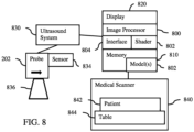
- Figure 8 shows one embodiment of a medical system for ultrasound compounding and/or deformation.
- the medical system includes the image processor 800, the memory 810, the display 820, the ultrasound system 830 and/or the medical scanner 840.
- the display 820, image processor 800, and/or memory 810 may be part of the medical scanner 840 (e.g., CT scanner), ultrasound system 830, computer, server, workstation, or another system for image processing medical images from a scan of a patient.
- a workstation or computer without the medical scanner 840 and/or ultrasound system 830 may be used as the medical system.
- a computer network is included for remote image generation of locally captured image data.
- the machine-learned models 802 are applied as standalone applications on the workstation or a local device or as a service deployed on network (cloud) architecture.
- the medical scanner 840 is not provided, such as where the pre-operative dataset was previously acquired and is stored in the memory 810.
- the ultrasound system 830 is a diagnostic medical ultrasound scanner.
- the ultrasound system 830 includes a probe 202 for scanning a field of view 836.
- An optional sensor 834 is provided on the probe 202 or for sensing the probe 202.
- the ultrasound system 830 may include a transmit beamformer, receive beamformer, B-mode detector, color flow or Doppler detector, filters, scan converter, and/or other components.
- the probe 202 is an ultrasound transducer with an array, such as a one-dimensional array, of transducer elements.
- the probe 202 is sized, shaped, and made of material for handheld or robotic use externally to the patient, such as for pressing against the skin of the patient to scan.
- the probe 202 is sized, shaped, and made of material for use in an orifice (e.g., trans-esophageal), for insertion into the patient (e.g., intra-operative probe or intracardiac catheter), or for intra-operative use.
- Other probes 202 may be used.
- the ultrasound system 830 uses the probe 202 to scan the field of view 836.
- a scan provides a 2D representation.
- the scanning is repeated to acquire multiple 2D representations.
- the field of view 836 shifts or moves to scan other planes in the tissue of the patient.
- the sensor 834 mounts to the probe 202 and/or is mounted to sense the probe 202.
- the sensor 834 may be a camera, electromagnetic sensor, accelerometer, strain gauge, pressure sensor, and/or another sensor to detect probe prose.
- the medical scanner 840 is the sensor, detecting the probe 202 or fiducials on the probe 202 while the probe 202 is within or adjacent to the patient.
- the image processor 800 compares (e.g., correlates with different shifts) 2D representations in a sequence to determine the change in position or pose.
- the sensor 834 is an ultrasound probe tracker configured to track the ultrasound probe 202 during acquisition of ultrasound data (e.g., during 2D scanning of a plane).
- the image processor 800 or another processor may operate with the sensor for tracking. Any image processing (e.g., fiducial recognition and position determination) is performed by the processor to track.
- the image processor 800 or another processor performs segmentation or other process on the ultrasound data.
- the ultrasound data is converted into a 2D field of signed distances for and object for each of the 2D representations.
- the medical scanner 840 is a diagnostic or therapeutic scanner (e.g., CT, x-ray, or MR scanner).
- the scanner 840 operates pursuant to one or more settings to scan a patient 842 resting on a bed or table 844.
- the settings control scanning including transmission, reception, reconstruction, and image processing.
- a scanning protocol is followed to generate data representing the patient 842.
- the patient 842 is imaged by the scanner 840 using the settings.
- the scanner 840 generates the pre-operative or other planning dataset, such as a volumetric representation of the patient 842 at a time prior to the scanning by the ultrasound system 830.
- the ultrasound data (e.g., 2D representations such as ultrasound images), segmentations (e.g., 2D signed distance fields), pre-operative data, compounded 3D representation, 3D deformation field, machine learned model 802, values of learned parameters, probe tracking data, rendered images, and/or other information are stored in a non-transitory computer readable memory, such as the memory 810.
- the memory 810 is configured to store the machine-learned neural network (e.g., model 802) formed as a neural field.
- the neural field was trained with joint optimization of probe pose and parameters of the neural field.
- Other models 802 may be stored, such as for different domains (e.g., liver verses kidney imaging).
- the memory 810 is an external storage device, RAM, ROM, database, and/or a local memory (e.g., solid state drive or hard drive). The same or different non-transitory computer readable media may be used for the instructions and other data.
- the memory 810 may be implemented using a database management system (DBMS) and residing on a memory, such as a hard disk, RAM, or removable media.
- DBMS database management system
- the memory 810 is internal to the processor 800 (e.g., cache).
- Non-transitory computer-readable storage media or memories such as a cache, buffer, RAM, removable media, hard drive, or other computer readable storage media (e.g., the memory 810).
- Non-transitory computer readable storage media include various types of volatile and nonvolatile storage media.
- the functions, acts or tasks illustrated in the figures or described herein are executed in response to one or more sets of instructions stored in or on computer readable storage media.
- the functions, acts or tasks are independent of the particular type of instructions set, storage media, processor or processing strategy and may be performed by software, hardware, integrated circuits, firmware, micro code, and the like, operating alone or in combination.
- the instructions are stored on a removable media device for reading by local or remote systems.
- the instructions are stored in a remote location for transfer through a computer network.
- the instructions are stored within a given computer, CPU, GPU, or system. Because some of the constituent system components and method steps depicted in the accompanying figures may be implemented in software, the actual connections between the system components (or the process steps) may differ depending upon the manner in which the present embodiments are programmed.
- the image processor 800 is a controller, control processor, general processor, micro-processor, tensor processor, digital signal processor, three-dimensional data processor, graphics processing unit, application specific integrated circuit, field programmable gate array, artificial intelligence processor, digital circuit, analog circuit, combinations thereof, or another now known or later developed device for processing image data.
- the image processor 800 is a single device, a plurality of devices, or a network of devices. For more than one device, parallel or sequential division of processing may be used. Different devices making up the image processor 800 may perform different functions.
- the image processor 800 is a control processor or other processor of the medical scanner 840 or ultrasound system 830.
- the image processor 800 operates pursuant to and is configured by stored instructions, hardware, and/or firmware to perform various acts described herein.
- the image processor 800 may include an interface 804.
- the interface 804 is configured to receive tracking data, ultrasound data, and/or pre-operative data at different rates and/or enforce synchronization.
- the interface 804 may be a standard or custom interface for receiving data and/or transmitting (e.g., outputting) data, such as images to the display 820 for visualization.
- the image processor 800 includes a shade compute (shader 802) rasterization (rasterizer), and/or parallel processors forming a rendering pipeline. Alternatively, other hardware components or just the processor is provided.
- the image processor 800 or another remote processor is configured to train machine learning architectures, such as model 802.
- the neural field is trained using training data.
- the neural field is trained using joint optimization to compound from probe tracking and images for a patient.
- the machine-learning model 802 is trained to generate the 3D representation, such as a compounding or 3D deformation field.
- the image processor 800 is configured to apply the machine-learned model(s) 802.
- the machine-learned models 802 may include a machine-learned network for 2D segmentation.
- the image processor 800 is configured to compound the ultrasound data into a volume representation using the neural field (model 802).
- the ultrasound data as compounded has refined positional information from the ultrasound probe tracker or sensor 834.
- the compounding forms the 3D representation or representations from ultrasound data (2D or 3D) from the ultrasound system 830 and tracking from the sensor 834.
- the 3D representation is ultrasound intensities, a segmented object in 3D, and/or a 3D deformation field.
- the model 802 used to compound ultrasound data also generates a 3D deformation field.
- the image processor 800 is configured to generate a 3D signed distance field or another segmentation of an object in response to input of 2D segmentations or 2D ultrasound data to the model 802.
- a different model (computational and/or machine-learned model 802) generates the 3D deformation field from the ultrasound scans.
- the image processor 800 is configured to generate an output, such as an image showing the segmentation.
- the image processor 800 using the shader 802 or another rendering component(s), renders one or more images.
- the images may be rendered from the 3D compounded ultrasound data.
- the images are rendered from pre-operative data.
- the rendered image from the pre-operative data may reflect tissue as deformed based on rendering using the 3D deformation field. Real-time imaging may be provided.
- the image processor 800 is configured to generate a visualization of the segmentation (contour). An image is rendered from a 3D segmentation.
- the display 820 is a CRT, LCD, projector, plasma, printer, tablet, smart phone or another now known or later developed display device for displaying the output, such as one or more rendered images from a volume representation.
- a sequence of images rendered during the surgery may be displayed to guide the surgeon.
- pre-operative images may be rendered in real-time with the ultrasound scanning based on a sequence of deformation fields generated from the ultrasound scanning (e.g., from the model 802 used to compound or another model 802).
- an ultrasound and/or pre-operative dataset image is rendered as a 3D segmentation using a signed distance field generated by the compounding model 802.
- FIG. 9 is a block diagram illustrating another example implementation of a system for visualization using modeling (e.g., a neural field) to compound and/or rendering at least one image using 3D deformation.
- Ultrasound B-mode 2D representations and probe poses 900 are provided to a processor for detection 910 at a low latency and to the compounding server 920 at the low latency.
- the detection 910 generates segmented or labeled 2D representations 912.
- the labeled representations 912 may be further processed, such as filtered or separated (e.g., different objects distinguished) 914.
- the compounding server 920 uses a neural field, neural fields, and/or other models to generate the 3D representations (e.g., ultrasound composite or compounded 3D representation 922, labeled or segmented 3D representation 926, and/or deformation field 3D representation 928.
- the server 920 may pass or also generate 2D ultrasound representations.
- the various representations are generated with the same or different latency.
- the visualization 630 is a graphics processing unit or other image generator for generating images from any one, combination, or all of the representations 922, 924, 926, and/or 928. The image generation may require different amounts of processing.
- FIG 10 shows an embodiment of an artificial neural network 1000, in accordance with one or more embodiments.
- artificial neural network are “neural network,” “artificial neural net,” or “neural net.”
- the artificial neural network 1000 may be used in part in, for example, the one or more machine learning based networks utilized for compounding or generating 3D deformation.
- the artificial neural network 1000 may be arranged or designed as a neural field for ultrasound 3D compounding and/or generating a deformation field.
- the artificial neural network 1000 includes nodes 1020-1032 and edges 1040-1042, wherein each edge 1040-1042 is a directed connection from a first node 1020-1032 to a second node 1020-1032.
- the first node 1020-1032 and the second node 1020-1032 are different nodes 1020-1032, it is also possible that the first node 1020-1032 and the second node 1020-1032 are identical.
- the edge 1040 is a directed connection from the node 1020 to the node 1023
- the edge 1041 is a directed connection from the node 1021 to the node 1023.
- An edge 1040-1042 from a first node 1020-1032 to a second node 1020-1032 is also denoted as "ingoing edge” for the second node 1020-1032 and as "outgoing edge” for the first node 1020-1032.
- the nodes 1020-1032 of the artificial neural network 1000 may be arranged in layers 1050-1053, wherein the layers may include an intrinsic order introduced by the edges 1040-1042 between the nodes 1020-1032.
- edges 1040-1042 may exist only between neighboring layers of nodes.
- the number of hidden layers 1051, 1052 may be chosen arbitrarily.
- the number of nodes 1020-1022 within the input layer 1050 usually relates to the number of input values of the neural network 1000
- the number of nodes 1031-1032 within the output layer 1053 usually relates to the number of output values of the neural network 1000.
- the number of layers and nodes corresponds to the coordinate system.
- Each node may be connected to adjacent nodes in any direction in a bi-directional edge.
- the input may be to all the nodes with output to all the nodes.
- the network architecture is an MLP with a small number of fully-connected layers, where the input to the network is a 3D position (mapped to a higher dimension using positional encoding), and the output of the network is a vector of parameters used by a volume renderer (attenuation, reflectance, scattering at the 3D position).
- w (m,n) i,j denotes the weight of the edge between the i-th node 1020-1032 of the m-th layer 1050-1053 and the j-th node 1020-1032 of the n-th layer 1050-1053. Furthermore, the abbreviation w (n) i,j is defined for the weight w (n,n+1) i,j .
- the input values are propagated through the neural network.
- the function f is a transfer function (another term is "activation function").
- transfer functions are step functions, sigmoid function (e.g., the logistic function, the generalized logistic function, the hyperbolic tangent, the Arctangent function, the error function, the smoothstep function) or rectifier functions.
- the transfer function is mainly used for normalization purposes.
- the values are propagated layer-wise or through adjacent nodes through the neural network 1000, wherein values of the input layer 1050 are given by the input of the neural network 1000, wherein values of the first hidden layer 1051 may be calculated based on the values of the input layer 1050 of the neural network 1000, wherein values of the second hidden layer 1052 may be calculated based in the values of the first hidden layer 1051, etc.
- training data includes training input data and training output data (denoted as t i ).
- training output data denoted as t i .
- the neural network 1000 is applied to the training input data to generate calculated output data.
- the training data and the calculated output data include a number of values, said number being equal with the number of nodes of the output layer.
- a comparison between the calculated output data and the training data is used to recursively adapt the weights within the neural network 1000 (backpropagation algorithm).
- Illustrative Embodiments for one set or type may be provided in or combined with other sets of types of Illustrative Embodiments.
- Illustrative Embodiment 1 A method for surgical guidance with compounded ultrasound imaging by an ultrasound system, the method comprising: scanning, by the ultrasound system, tissue of a patient, the scanning resulting in two-dimensional (2D) representations; tracking positions of the 2D representations; compounding the 2D representations by input of the positions and 2D representations to a neural field, the neural field trained with a joint optimization of poses and parameters of the neural field, the compounding providing a three-dimensional (3D) representation of the patient; rendering a first image from the 3D representation; and displaying the first image.
- 2D two-dimensional
- Illustrative Embodiment 2 The method of Illustrative Embodiment 1, wherein tracking comprises tracking with a camera, probe detection, or electromagnetic sensing.
- Illustrative Embodiment 3 The method of any of Illustrative Embodiments 1-2, wherein scanning comprises scanning while moving a transducer probe relative to the patient.
- Illustrative Embodiment 4 The method of any of Illustrative Embodiments 1-3, wherein the 2D representations comprise images of ultrasound intensity, wherein compounding comprises providing the 3D representation as voxels representing intensity distribution in three dimensions, and wherein rendering comprises rendering the first image as ultrasound intensities as a function of location in two dimensions.
- Illustrative Embodiment 5 The method of any of Illustrative Embodiments 1-4, wherein the 2D representations comprise 2D segmentations of an object, wherein compounding comprises providing, by the neural field, a signed distance field representing a 3D segmentation of the object as the 3D representation, and wherein rendering the first image comprises rendering the first image from the 3D segmentation of the object.
- Illustrative Embodiment 6 The method of any of Illustrative Embodiments 1-5, wherein compounding comprises compounding by the neural field, the neural field trained with a loss based on comparison of a rendering of an output with one of the 2D representations.
- Illustrative Embodiment 7 The method of any of Illustrative Embodiments 1-6, wherein compounding comprises compounding by the neural field, the neural field comprising a coordinate-based neural network.
- Illustrative Embodiment 8 The method of Illustrative Embodiment 7, wherein compounding comprises compounding where the coordinate-based neural network comprises sinusoidal, multiresolution hash or another positional encoding.
- Illustrative Embodiment 9 The method of any of Illustrative Embodiments 1-8, wherein rendering comprises sampling the neural field directly.
- Illustrative Embodiment 10 The method of any of Illustrative Embodiments 1-9, wherein rendering comprises view optimization with differentiable rendering.
- Illustrative Embodiment 11 The method of any of Illustrative Embodiments 1-10, wherein compounding comprises providing the 3D representation as a deformation field based on the scanning as real-time ultrasound, and wherein rendering comprises rendering a pre-operative image based on the deformation field.
- Illustrative Embodiment 12 The method of Illustrative Embodiment 11, wherein compounding comprises compounding with the neural field, the neural field trained using differentiable deformable volume rendering.
- a medical system for ultrasound compounding comprising: an ultrasound probe tracker configured to track an ultrasound probe during acquisition of ultrasound data; a memory configured to store a machine learning neural network formed as a neural field; an image processor configured to compound the ultrasound data into a volume representation using training of the neural field as a joint optimization of probe pose and parameters of the neural field, the ultrasound data as compounded having refined positional information from the ultrasound probe tracker; and a display configured to display an image from the volume representation.
- Illustrative Embodiment 14 The system of Illustrative Embodiment 13, wherein the volume representation comprises a deformation field, and wherein the image comprises a pre-operative image rendered using the deformation field.
- Illustrative Embodiment 15 The system of any of Illustrative Embodiments 13-14, wherein the ultrasound data comprises two-dimensional fields of signed distances for an object, wherein the volume representation comprises a signed distance field for the object, and wherein the image comprises a three-dimensional segmentation rendered using the signed distance field.
- Illustrative Embodiment 16 A method for surgical guidance with compounded ultrasound imaging by an ultrasound system, the method comprising: scanning, by the ultrasound system, tissue of a patient, the scanning resulting in two-dimensional (2D) representations; tracking pressures corresponding to the 2D representations; generating a three-dimensional (3D) deformation field by a model from the pressures and the 2D representations; rendering, in real-time with the scanning, a pre-operative image using the 3D deformation field; and displaying the pre-operative image.
- 2D two-dimensional
- Illustrative Embodiment 18 The method of any of Illustrative Embodiments 16-17, wherein rendering comprises using the deformation field as an indexing texture.
- Illustrative Embodiment 19 The method of any of Illustrative Embodiments 16-18, wherein rendering comprises computing data sampling locations from splines generated from the deformation field.
- Illustrative Embodiment 20 The method of any of Illustrative Embodiments 16-19, wherein rendering comprises deforming a pre-operative volume representation based on the deformation field in a compute shader and rendering from the deformed pre-operative volume representation.
- Illustrative Embodiment 21 The method of any of Illustrative Embodiments 16-20, wherein displaying comprises displaying the pre-operative image synchronized with an ultrasound image from the scanning.
Landscapes
- Health & Medical Sciences (AREA)
- Life Sciences & Earth Sciences (AREA)
- Engineering & Computer Science (AREA)
- Surgery (AREA)
- Physics & Mathematics (AREA)
- Nuclear Medicine, Radiotherapy & Molecular Imaging (AREA)
- Public Health (AREA)
- Molecular Biology (AREA)
- Medical Informatics (AREA)
- Heart & Thoracic Surgery (AREA)
- Animal Behavior & Ethology (AREA)
- General Health & Medical Sciences (AREA)
- Biomedical Technology (AREA)
- Veterinary Medicine (AREA)
- Pathology (AREA)
- Radiology & Medical Imaging (AREA)
- Biophysics (AREA)
- Computer Vision & Pattern Recognition (AREA)
- General Physics & Mathematics (AREA)
- Remote Sensing (AREA)
- Radar, Positioning & Navigation (AREA)
- Theoretical Computer Science (AREA)
- Computer Graphics (AREA)
- Robotics (AREA)
- Acoustics & Sound (AREA)
- General Engineering & Computer Science (AREA)
- Computer Networks & Wireless Communication (AREA)
- Gynecology & Obstetrics (AREA)
- Oral & Maxillofacial Surgery (AREA)
- Ultra Sonic Daignosis Equipment (AREA)
Applications Claiming Priority (2)
| Application Number | Priority Date | Filing Date | Title |
|---|---|---|---|
| US202363597445P | 2023-11-09 | 2023-11-09 | |
| US18/800,174 US20250152251A1 (en) | 2023-11-09 | 2024-08-12 | Surgical Guidance with Compounded Ultrasound Imaging |
Publications (2)
| Publication Number | Publication Date |
|---|---|
| EP4552580A2 true EP4552580A2 (de) | 2025-05-14 |
| EP4552580A3 EP4552580A3 (de) | 2025-07-23 |
Family
ID=93432315
Family Applications (1)
| Application Number | Title | Priority Date | Filing Date |
|---|---|---|---|
| EP24211131.8A Pending EP4552580A3 (de) | 2023-11-09 | 2024-11-06 | Chirurgische führung mit zusammengesetzter ultraschallbildgebung |
Country Status (3)
| Country | Link |
|---|---|
| US (1) | US20250152251A1 (de) |
| EP (1) | EP4552580A3 (de) |
| CN (1) | CN119970225A (de) |
Families Citing this family (1)
| Publication number | Priority date | Publication date | Assignee | Title |
|---|---|---|---|---|
| CN120788735B (zh) * | 2025-09-03 | 2025-11-21 | 浙江大学 | 基于深度学习的前列腺精准穿刺机器人路径规划方法 |
Family Cites Families (4)
| Publication number | Priority date | Publication date | Assignee | Title |
|---|---|---|---|---|
| GB0121984D0 (en) * | 2001-09-11 | 2001-10-31 | Isis Innovation | Method and apparatus for ultrasound examination |
| EP2807978A1 (de) * | 2013-05-28 | 2014-12-03 | Universität Bern | Verfahren und System zur 3D-Erfassung von Ultraschallbildern |
| US12207969B2 (en) * | 2019-11-21 | 2025-01-28 | Koninklijke Philips N.V. | Systems and methods for obtaining medical ultrasound images |
| US12295797B2 (en) * | 2022-02-03 | 2025-05-13 | Medtronic Navigation, Inc. | Systems, methods, and devices for providing an augmented display |
-
2024
- 2024-08-12 US US18/800,174 patent/US20250152251A1/en active Pending
- 2024-11-06 EP EP24211131.8A patent/EP4552580A3/de active Pending
- 2024-11-08 CN CN202411590004.XA patent/CN119970225A/zh active Pending
Also Published As
| Publication number | Publication date |
|---|---|
| US20250152251A1 (en) | 2025-05-15 |
| CN119970225A (zh) | 2025-05-13 |
| EP4552580A3 (de) | 2025-07-23 |
Similar Documents
| Publication | Publication Date | Title |
|---|---|---|
| US12042232B2 (en) | Left atrial appendage closure guidance in medical imaging | |
| US12285295B2 (en) | Ultrasound system with a neural network for producing images from undersampled ultrasound data | |
| CN110010249B (zh) | 基于视频叠加的增强现实手术导航方法、系统及电子设备 | |
| EP3003161B1 (de) | Verfahren zur 3d-erfassung von ultraschallbildern | |
| EP3155590B1 (de) | Verarbeitungsvorrichtung und -verfahren für medizinische bilder | |
| US20210065388A1 (en) | Registering a two-dimensional image with a three-dimensional image | |
| EP3561768B1 (de) | Visualisierung von lungenfissuren in der medizinischen bildgebung | |
| WO2015191414A2 (en) | Landmark detection with spatial and temporal constraints in medical imaging | |
| KR20090059048A (ko) | 3차원 이미지 및 표면 맵핑으로부터의 해부학적 모델링 방법 및 시스템 | |
| JP2008259696A (ja) | 三次元画像処理装置および方法並びにプログラム | |
| US10891776B2 (en) | Imaging system and method | |
| Weng et al. | Three-dimensional surface reconstruction using optical flow for medical imaging | |
| CN101292266A (zh) | 超声成像系统和方法 | |
| CN106030657B (zh) | 医学4d成像中的运动自适应可视化 | |
| EP4552580A2 (de) | Chirurgische führung mit zusammengesetzter ultraschallbildgebung | |
| US9224240B2 (en) | Depth-based information layering in medical diagnostic ultrasound | |
| Gerats et al. | Dynamic depth-supervised NeRF for multi-view RGB-D operating room images | |
| Savochkina | First trimester gaze and visual-assisted probe motion guidance for obstetric ultrasound scanning | |
| Gerats et al. | Dynamic Depth-Supervised NeRF for Multi-view RGB-D Operating Room | |
| Øye et al. | Illustrative couinaud segmentation for ultrasound liver examinations | |
| Yoshinaga et al. | Development of augmented reality body-mark system to support echography | |
| Lai et al. | Designs and Implementation of Three Dimensional Nuchal Translucency | |
| XIANHE | Digitally reconstructed wall radiographs | |
| Erstellt von Yeganeh | Sensorless US compounding |
Legal Events
| Date | Code | Title | Description |
|---|---|---|---|
| PUAI | Public reference made under article 153(3) epc to a published international application that has entered the european phase |
Free format text: ORIGINAL CODE: 0009012 |
|
| STAA | Information on the status of an ep patent application or granted ep patent |
Free format text: STATUS: REQUEST FOR EXAMINATION WAS MADE |
|
| 17P | Request for examination filed |
Effective date: 20241106 |
|
| AK | Designated contracting states |
Kind code of ref document: A2 Designated state(s): AL AT BE BG CH CY CZ DE DK EE ES FI FR GB GR HR HU IE IS IT LI LT LU LV MC ME MK MT NL NO PL PT RO RS SE SI SK SM TR |
|
| PUAL | Search report despatched |
Free format text: ORIGINAL CODE: 0009013 |
|
| AK | Designated contracting states |
Kind code of ref document: A3 Designated state(s): AL AT BE BG CH CY CZ DE DK EE ES FI FR GB GR HR HU IE IS IT LI LT LU LV MC ME MK MT NL NO PL PT RO RS SE SI SK SM TR |
|
| RIC1 | Information provided on ipc code assigned before grant |
Ipc: A61B 8/00 20060101AFI20250613BHEP Ipc: G01S 15/89 20060101ALI20250613BHEP Ipc: A61B 34/20 20160101ALI20250613BHEP Ipc: A61B 90/00 20160101ALI20250613BHEP |