EP4552516A1 - Inhalation device, control method, and program - Google Patents
Inhalation device, control method, and program Download PDFInfo
- Publication number
- EP4552516A1 EP4552516A1 EP22950229.9A EP22950229A EP4552516A1 EP 4552516 A1 EP4552516 A1 EP 4552516A1 EP 22950229 A EP22950229 A EP 22950229A EP 4552516 A1 EP4552516 A1 EP 4552516A1
- Authority
- EP
- European Patent Office
- Prior art keywords
- inhalation
- period
- heating
- time
- mode
- Prior art date
- Legal status (The legal status is an assumption and is not a legal conclusion. Google has not performed a legal analysis and makes no representation as to the accuracy of the status listed.)
- Pending
Links
Images




Classifications
-
- A—HUMAN NECESSITIES
- A24—TOBACCO; CIGARS; CIGARETTES; SIMULATED SMOKING DEVICES; SMOKERS' REQUISITES
- A24F—SMOKERS' REQUISITES; MATCH BOXES; SIMULATED SMOKING DEVICES
- A24F40/00—Electrically operated smoking devices; Component parts thereof; Manufacture thereof; Maintenance or testing thereof; Charging means specially adapted therefor
- A24F40/50—Control or monitoring
-
- A—HUMAN NECESSITIES
- A24—TOBACCO; CIGARS; CIGARETTES; SIMULATED SMOKING DEVICES; SMOKERS' REQUISITES
- A24F—SMOKERS' REQUISITES; MATCH BOXES; SIMULATED SMOKING DEVICES
- A24F40/00—Electrically operated smoking devices; Component parts thereof; Manufacture thereof; Maintenance or testing thereof; Charging means specially adapted therefor
- A24F40/50—Control or monitoring
- A24F40/57—Temperature control
-
- A—HUMAN NECESSITIES
- A24—TOBACCO; CIGARS; CIGARETTES; SIMULATED SMOKING DEVICES; SMOKERS' REQUISITES
- A24F—SMOKERS' REQUISITES; MATCH BOXES; SIMULATED SMOKING DEVICES
- A24F40/00—Electrically operated smoking devices; Component parts thereof; Manufacture thereof; Maintenance or testing thereof; Charging means specially adapted therefor
- A24F40/40—Constructional details, e.g. connection of cartridges and battery parts
-
- A—HUMAN NECESSITIES
- A24—TOBACCO; CIGARS; CIGARETTES; SIMULATED SMOKING DEVICES; SMOKERS' REQUISITES
- A24F—SMOKERS' REQUISITES; MATCH BOXES; SIMULATED SMOKING DEVICES
- A24F40/00—Electrically operated smoking devices; Component parts thereof; Manufacture thereof; Maintenance or testing thereof; Charging means specially adapted therefor
- A24F40/40—Constructional details, e.g. connection of cartridges and battery parts
- A24F40/46—Shape or structure of electric heating means
-
- A—HUMAN NECESSITIES
- A24—TOBACCO; CIGARS; CIGARETTES; SIMULATED SMOKING DEVICES; SMOKERS' REQUISITES
- A24F—SMOKERS' REQUISITES; MATCH BOXES; SIMULATED SMOKING DEVICES
- A24F40/00—Electrically operated smoking devices; Component parts thereof; Manufacture thereof; Maintenance or testing thereof; Charging means specially adapted therefor
- A24F40/20—Devices using solid inhalable precursors
Definitions
- the present invention relates to an inhalation device, a control method, and a program.
- an inhalation device that generates aerosol to which a flavor component is applied and allows a user to inhale the generated aerosol.
- Such an inhalation device typically generates aerosol by heating a substrate containing an aerosol source with a heating portion (also referred to as a "heating element"), which is an electrical resistance heater or an induction heater, and delivers the aerosol to the user.
- a heating portion also referred to as a "heating element”
- a heating portion also referred to as a "heating element”
- a control profile also referred to as a "heating profile” or a "target temperature profile
- Patent Literature 1 Japanese Patent Application Laid-Open Publication No. 2015-524260A
- the heating profile is designed to optimize a flavor experienced by the user on the premise that standard inhalation is performed
- the standard inhalation as the premise in the heating profile is not necessarily performed to the inhalation device.
- an inhalation mode of the inhalation device may not only individually differ for each user, but also vary depending on the feeling at the time of inhalation or the like even for the same user.
- an event may occur that the heating by the heating portion is stopped while the sufficient aerosol source remains in the substrate, or the heating by the heating portion is unnecessarily continued while the aerosol source in the substrate is depleting.
- the occurrence of such an event is not preferable from the viewpoint of improving user satisfaction with respect to the inhalation device (in other words, the commerciality of the inhalation device).
- the present invention provides an inhalation device, a control method, and a program that are capable of providing a high-quality smoking experience to a user by appropriately consuming a substrate containing an aerosol source even when inhalation in an inhalation mode different from standard inhalation as the premise in a heating profile is performed.
- a first invention relates to an inhalation device that includes:
- a second invention relates to a control method of executing, by a computer that controls an inhalation device including a heating portion configured to generate an aerosol by heating a substrate containing an aerosol source and allowing a user to inhale the aerosol generated by the heating portion, a process comprising:
- a third invention relates to a program for causing a computer, which controls an inhalation device including a heating portion configured to generate aerosol by heating a substrate containing an aerosol source and allowing a user to inhale the aerosol generated by the heating portion, to execute a process comprising:
- an inhalation device, a control method, and a program that are capable of providing a high-quality smoking experience to a user by appropriately consuming a substrate containing an aerosol source even when inhalation in an inhalation mode different from standard inhalation as the premise in a heating profile is performed.
- the inhalation device is a device that generates a substance to be inhaled by a user and allows the user to inhale the generated substance.
- the substance generated by the inhalation device according to the present embodiment is aerosol, but the substance is not limited to the aerosol, and may be a gas.
- FIG. 1 is a schematic diagram schematically showing the inhalation device according to the present embodiment.
- a stick-type substrate 150 having a flavor generating substrate such as a filler containing an aerosol source and a flavor source which are inhalation component sources is inserted.
- the stick-type substrate 150 inserted into the inhalation device 100 generates aerosol containing a flavor component by being heated from an outer periphery thereof.
- the aerosol source can use, for example, a polyhydric alcohol such as glycerin and propylene glycol or a liquid such as water, but the aerosol source is not limited to the liquid, and may be a solid.
- the flavor source is a constituent element for applying the flavor component to the generated aerosol, and contains, for example, a tobacco-based flavor component or a non-tobacco-based flavor component.
- the tobacco-based flavor component can include tobacco granules obtained by forming a tobacco raw material into granules, and a shredded tobacco.
- the non-tobacco-based flavor component can include a plant other than tobacco (for example, mint, Kampo herbal medicine, or herb) and a perfume such as menthol.
- the tobacco-based flavor component or the non-tobacco-based flavor component may be contained in the aerosol source.
- the aerosol source may contain a drug.
- the inhalation device 100 includes a power supply portion 111, a sensor portion 112, a notification portion 113, a storage portion 114, a communication portion 115, a control unit 116, a heating portion 121, a holding portion 140, and a heat insulation portion 144.
- the power supply portion 111 stores electric power.
- the power supply portion 111 feeds the electric power to each constituent element of the inhalation device 100 based on control by the control unit 116.
- the power supply portion 111 may be implemented by, for example, a rechargeable battery such as a lithium ion secondary battery.
- the sensor portion 112 acquires various types of information related to the inhalation device 100.
- the sensor portion 112 is implemented by a pressure sensor such as a condenser microphone, a flow rate sensor, a temperature sensor, a voltage sensor, or the like, and acquires a value associated with inhalation by the user.
- the sensor portion 112 may include a pressure sensor (hereinafter, also referred to as a "puff sensor”) that detects a pressure in the inhalation device 100.
- a pressure sensor hereinafter, also referred to as a "puff sensor”
- the control unit 116 can detect inhalation to the inhalation device 100 based on a detection value of the puff sensor.
- the sensor portion 112 may include a flow rate sensor that detects a flow rate generated by the inhalation to the inhalation device 100 (hereinafter, also simply referred to as the "flow rate"). Further, as another example, the sensor portion 112 may include a temperature sensor (hereinafter, also referred to as a "puff thermistor”) that detects a temperature of the heating portion 121 (or a predetermined portion near the heating portion 121). As another example, the sensor portion 112 may include a voltage sensor that detects a potential difference (hereinafter, also referred to as a "voltage”) applied to a heating resistor constituting the heating portion 121.
- a potential difference hereinafter, also referred to as a "voltage
- the sensor portion 112 may further include an input device such as an operation button or an operation switch that receives input of information from the user, and may acquire the information input from the user.
- an input device such as an operation button or an operation switch that receives input of information from the user, and may acquire the information input from the user.
- the notification portion 113 notifies the user of information.
- the notification portion 113 may implemented by, for example, a light emitting device that emits light, a display device that displays an image, a sound output device that outputs a sound, a vibration device that vibrates, or the like.
- a light emitting device for example, a light emitting diode (LED) can be adopted.
- a display device for example, a liquid crystal display or an organic electro luminescence diode (OELD) display can be adopted.
- the sound output device for example, a speaker capable of converting an electric signal representing a sound into a physical sound (that is, vibration of air) can be adopted.
- a vibrator including an eccentric weight and a motor for rotating the eccentric weight can be adopted.
- the storage portion 114 stores various types of information (for example, various data and various programs) for an operation of the inhalation device 100.
- the storage portion 114 may be implemented by, for example, a nonvolatile storage medium such as a flash memory.
- Examples of the information stored in the storage portion 114 can include a heating profile.
- the heating profile refers to information that defines a time-series transition of a target temperature which is a target value of the temperature of the heating portion 121 (hereinafter, also simply referred to as the "target temperature").
- target temperature An example of the heating profile will be described later with reference to FIG. 2 .
- the communication portion 115 is a communication interface that can perform communication in accordance with any wired or wireless communication standard.
- wireless communication for example, Wi-Fi (registered trademark), Bluetooth (registered trademark), or near field communication (NFC) may be adopted as the communication standard.
- NFC near field communication
- communication may be performed by an external connection terminal such as a universal serial bus (USB) and a data communication cable.
- USB universal serial bus
- the control unit 116 functions as an arithmetic processing device and a control device, and controls overall operations in the inhalation device 100 according to various programs. Since an example of the control performed by the control unit 116 will be described later, the description thereof is omitted here.
- the control unit 116 is implemented by, for example, an electronic circuit such as a central processing unit (CPU) or a microprocessor.
- the holding portion 140 has an internal space 141, and holds the stick-type substrate 150 while accommodating a part of the stick-type substrate 150 in the internal space 141.
- the holding portion 140 has an opening 142 through which the internal space 141 communicates with the outside, and holds the stick-type substrate 150 inserted into the internal space 141 from the opening 142.
- the holding portion 140 is a cylindrical body having the opening 142 and a bottom portion 143 as a bottom surface, and defines the columnar internal space 141.
- the holding portion 140 also has a function of defining a flow path of air supplied to the stick-type substrate 150.
- An air inlet hole which is an inlet of the air to the flow path, is disposed, for example, in the bottom portion 143.
- an air outlet hole which is an outlet of the air from the flow path, is the opening 142.
- the stick-type substrate 150 includes a substrate portion 151 and an inhalation port portion 152.
- the substrate portion 151 includes, for example, the aerosol source.
- the inhalation port portion 152 protrudes from the opening 142.
- the air flows into the internal space 141 from the air inlet hole (not shown), and reaches the mouth of the user together with the aerosol generated from the substrate portion 151.
- the heating portion 121 heats the aerosol source to atomize the aerosol source to generate the aerosol.
- the heating portion 121 is formed in a film shape, and is disposed to cover an outer periphery of the holding portion 140.
- the heating portion 121 generates heat when being supplied with the electric power from the power supply portion 111.
- the substrate portion 151 of the stick-type substrate 150 is heated from an outer periphery, and the aerosol is generated.
- the supply of the electric power from the power supply portion 111 to the heating portion 121 may be started when the sensor portion 112 detects that the user starts the inhalation and/or that predetermined information is input. Then, the supply of the electric power from the power supply portion 111 to the heating portion 121 may be stopped when the sensor portion 112 detects that the user finishes the inhalation and/or that predetermined information is input. As described above, the supply of the electric power from the power supply portion 111 to the heating portion 121 may be controlled by the control unit 116.
- the heat insulation portion 144 prevents heat transfer from the heating portion 121 to other constituent elements.
- the heat insulation portion 144 is made of a vacuum heat insulation material or an aerogel heat insulation material.
- the heating portion 121 may be formed in a blade shape and disposed to protrude from the bottom portion 143 of the holding portion 140 into the internal space 141.
- the blade-shaped heating portion 121 is inserted into the substrate portion 151 of the stick-type substrate 150, and heats the substrate portion 151 of the stick-type substrate 150 from the inside.
- the heating portion 121 may be disposed to cover the bottom portion 143 of the holding portion 140.
- the heating portion 121 may be implemented by a combination of two or more of a first heating portion covering the outer periphery of the holding portion 140, a blade-shaped second heating portion, and a third heating portion covering the bottom portion 143 of the holding portion 140.
- the holding portion 140 may include an opening and closing mechanism such as a hinge that opens and closes a part of an outer shell forming the internal space 141.
- the holding portion 140 may open and close the outer shell to sandwich and hold the stick-type substrate 150 inserted into the internal space 141.
- the heating portion 121 may be provided at a sandwiching and holding place in the holding portion 140 and heat the stick-type substrate 150 while pressing the stick-type substrate 150.
- a method for atomizing the aerosol source is not limited to heating by the heating portion 121, and may be induction heating, for example.
- the inhalation device 100 may include a plurality of types of aerosol sources. A plurality of types of aerosol generated from the plurality of types of aerosol sources may be mixed to cause a chemical reaction, thereby generating another type of aerosol.
- the heating profile which is information defining the time-series transition of the target temperature, can be, for example, information defining a time length and the target temperature of each time section included in a plurality of time sections consecutive along a time axis. Further, in the heating profile, the target temperature of the time section may be defined without determining the time length of the time section, and the time section may be ended when the target temperature is reached.
- FIG. 2 is a diagram showing an example of the heating profile according to the present embodiment.
- the vertical axis in FIG. 2 represents the target temperature [°C].
- the vertical axis in FIG. 2 represents a time [sec], and more specifically represents an elapsed time from the start of a control based on the heating profile.
- the heating profile according to the present embodiment defines the time length and the target temperature of each time section among a first time section S1, a second time section S2, a third time section S3, a fourth time section S4, a fifth time section S5, and a sixth time section S6 consecutive along the time axis.
- time sections that is, the first time section S1, the second time section S2, the third time section S3, the fourth time section S4, the fifth time section S5, and the sixth time section S6 are provided in this order from the front in time series. Then, with the end of the sixth time section S6 as the last time section, the heating by the heating portion 121 (in other words, the supply of the electric power to the heating portion 121) is stopped. Accordingly, as indicated by the dash-dotted line in FIG. 2 , the temperature of the heating portion 121 gradually decreases after the sixth time section S6 ends.
- the first time section S1 is a time section in which the time length is tm1 [sec] and the target temperature is T1 [°C].
- the second time section S2 is a time section in which the time length is tm2 [sec] and the target temperature is T1 [°C].
- the third time section S3 is a time section in which the time length is tm3 [sec] and the target temperature is T2 [°C] (where T2 ⁇ T1).
- the fourth time section S4 is a time section in which the time length is tm4 [sec] and the target temperature is T2 [°C].
- the fourth time section S4 is the longest time section. In other words, tm4 is longer than any one of tm1 to tm3 described above and tm5 and tm6 to be described below.
- the fifth time section S5 is a time section in which the time length is tm5 [sec] and the target temperature is T3 [°C] (where T3 > T2 and T3 ⁇ T1).
- the sixth time section S6 is a time section in which the time length is tm6 [sec] and the target temperature is T3 [°C]. As described above, the sixth time section S6 is the last time section and is a time section immediately before the stop of the heating by the heating portion 121.
- the time sections included in the heating profile can be roughly divided into three types of sections, that is, a heating section, a cooling section, and a temperature maintenance section.
- the heating section is a time section in which the heating portion 121 is heated (in other words, the temperature of the heating portion 121 increases).
- the heating section is a time section in which the target temperature is assumed to be higher than the temperature of the heating portion 121 at the start (for example, the target temperature of the previous time section).
- the first time section S1 and the fifth time section S5 are the heating section.
- the first time section S1 is also referred to as a "first heating section S1”
- the fifth time section S5 is also referred to as a "second heating section S5".
- the cooling section is a time section in which the heating portion 121 is cooled (in other words, the temperature of the heating portion 121 decreases).
- the cooling section is a time section in which the target temperature is assumed to be lower than the temperature of the heating portion 121 at the start (for example, the target temperature of the previous time section).
- the third time section S3 is the heating section.
- the third time section S3 is also referred to as a "cooling section S3".
- the temperature maintenance section is a time section in which the control unit 116 controls the heating portion 121 to maintain the temperature thereof at a constant temperature.
- the temperature maintenance section is a time section in which the target temperature is assumed to be approximately equal to the temperature of the heating portion 121 at the start (for example, the target temperature of the previous time section).
- the second time section S2, the fourth time section S4, and the sixth time section S6 are the temperature maintenance section.
- the second time section S2 is also referred to as a "first temperature maintenance section S2”
- the fourth time section S4 is also referred to as a "second temperature maintenance section S4"
- the sixth time section S6 is also referred to as a "third temperature maintenance section S6".
- the temperature of the heating portion 121 is controlled to be maintained at the constant temperature in the temperature maintenance section, in practice, the temperature of the heating portion 121 may vary. Examples of factors that cause the temperature of the heating portion 121 to vary in the temperature maintenance section include a decrease in the temperature of the heating portion 121 due to the inhalation by the user, and hunting in a proportional-integral-differential (PID) controller.
- PID proportional-integral-differential
- the heating profile according to the present embodiment includes the first heating section S1 provided first, the cooling section S3 provided after the first heating section S1 and having the target temperature lower than that of the first heating section S1, the third temperature maintenance section S6 provided after the cooling section S3 and having the target temperature higher than that of the cooling section S3, and the second temperature maintenance section S4 as a low-temperature section having the target temperature lower than that of the third temperature maintenance section S6.
- the first heating section S1, the first temperature maintenance section S2, the cooling section S3, the second temperature maintenance section S4, the second heating section S5, and the third temperature maintenance section S6 are provided in this order from the front in time series.
- the target temperature of the heating portion 121 is set to T1 [°C] in the first heating section S1 and the first temperature maintenance section S2, is set to T2 [°C] (T2 ⁇ T1) in the cooling section S3 and the second temperature maintenance section S4, and is set to T3 [°C] (T2 ⁇ T3 ⁇ T1) in the second heating section S5 and the third temperature maintenance section S6.
- a period in which a sufficient amount of aerosol is assumed to be generated is also referred to as an "inhalation-enabled period (or a puff-enabled period)".
- a period from the start of the heating to the start of the inhalation-enabled period is also referred to as a "pre-heating period”.
- the heating performed in the pre-heating period is also referred to as "pre-heating”.
- the first heating section S1 is the pre-heating period.
- the first temperature maintenance section S2, the cooling section S3, the second temperature maintenance section S4, the second heating section S5, and the third temperature maintenance section S6 are the inhalation-enabled period.
- the notification portion 113 of the inhalation device 100 notifies the user of a timing at which the inhalation-enabled period starts and a timing at which the inhalation-enabled period ends. That is, the notification portion 113 notifies the user at a timing when the first temperature maintenance section S2 starts (in other words, a timing when the first heating section S1 ends) and a timing when the third temperature maintenance section S6 ends. In this way, by notifying the user of the timing at which the inhalation-enabled period starts and the timing at which the inhalation-enabled period ends, the user can perform the inhalation to the inhalation device 100 in the inhalation-enabled period with reference to the notification.
- a mode of the notification performed at the timing when the inhalation-enabled period starts (that is, the timing when the first temperature maintenance section S2 starts) and a mode of the notification performed at the timing when the inhalation-enabled period ends (that is, the timing when the third temperature maintenance section S6 ends) may be different from each other.
- a mode of the notification performed at the timing when the inhalation-enabled period starts (that is, the timing when the first temperature maintenance section S2 starts)
- a mode of the notification performed at the timing when the inhalation-enabled period ends (that is, the timing when the third temperature maintenance section S6 ends) may be different from each other.
- the control unit 116 of the inhalation device 100 controls an operation of the heating portion 121 based on the heating profile. Accordingly, the aerosol is generated as planned by the heating profile.
- the heating profile is typically designed to optimize a flavor experienced by the user when the user inhales the aerosol generated from the stick-type substrate 150. Therefore, by controlling the operation of the heating portion 121 based on the heating profile, it is possible to optimize the flavor experienced by the user.
- the control unit 116 starts the control of the heating portion 121 in a control mode defined by the heating profile.
- the generation request for the aerosol can be, for example, an operation of instructing the start of heating.
- the operation of instructing the start of heating can be pressing a predetermined operation button provided in the inhalation device 100.
- the operation of instructing the start of heating may be an inhalation operation to the inhalation device 100 or reception of predetermined information from another device such as a smartphone.
- the control unit 116 can detect the generation request for the aerosol based on, for example, information acquired by the sensor portion 112 or the communication portion 115.
- the control unit 116 controls the operation of the heating portion 121 based on a difference between the target temperature corresponding to an elapsed time from the start of the control based on the heating profile and an actual temperature of the heating portion 121 (hereinafter, also referred to as the "actual temperature"). More specifically, at this time, the control unit 116 controls the temperature of the heating portion 121 such that a time-series transition of the actual temperature of the heating portion 121 is the same as the time-series transition of the target temperature defined in the heating profile.
- the temperature control of the heating portion 121 can be achieved by, for example, a known feedback control.
- the control unit 116 supplies the electric power from the power supply portion 111 to the heating portion 121 in a pulse form by pulse width modulation (PWM) or pulse frequency modulation (PFM).
- PWM pulse width modulation
- PFM pulse frequency modulation
- the control unit 116 can control the temperature of the heating portion 121 by adjusting a duty ratio of an electric power pulse.
- the control unit 116 may control the electric power supplied to the heating portion 121, for example, the duty ratio based on the difference between the actual temperature and the target temperature and the like. Further, the feedback control may be the PID control, for example. Alternatively, the control unit 116 may perform a simple ON-OFF control. For example, the control unit 116 may execute the heating by the heating portion 121 until the actual temperature reaches the target temperature, stop the heating by the heating portion 121 when the actual temperature reaches the target temperature, and execute the heating by the heating portion 121 again when the actual temperature becomes lower than the target temperature.
- the temperature of the heating portion 121 can be acquired (in other words, quantified), for example, by measuring or estimating an electrical resistance value of the heating resistor constituting the heating portion 121. This is because the electrical resistance value of the heating resistor changes according to the temperature.
- the electrical resistance value of the heating resistor can be estimated (that is, acquired), for example, by measuring a voltage reduction amount in the heating resistor.
- the voltage reduction amount in the heating resistor can be measured (that is, acquired) by the voltage sensor that measures the potential difference applied to the heating resistor.
- the temperature of the heating portion 121 may be measured by the temperature sensor (the puff thermistor) provided near the heating portion 121.
- control unit 116 stops the heating by the heating portion 121 at a timing when a predetermined time has elapsed from the start of the control based on the heating profile.
- a timing at which the heating by the heating portion 121 is stopped is, for example, a timing at which the last time section (the third temperature maintenance section S6 in the example according to the present embodiment) in the heating profile ends.
- the heating by the heating portion 121 is typically stopped at a timing at which it is assumed that at least one of the aerosol source and the flavor component of the stick-type substrate 150 decreases and the sufficient amount of aerosol to which an appropriate amount of the flavor component is applied cannot be delivered to the user.
- the heating profile is designed such that the last time section ends at a timing at which it is assumed that the aerosol source or the flavor component of the stick-type substrate 150 decreases to the extent that the sufficient amount of aerosol to which the appropriate amount of the flavor component is applied cannot be delivered to the user on the premise that standard inhalation is performed.
- the aerosol source and the flavor component of the stick-type substrate 150 are also reduced by performing the inhalation to the inhalation device 100. Therefore, even before the predetermined time elapses from the start of the control based on the heating profile, when the inhalation is performed a predetermined number of times (for example, 15 times) from the start of the control based on the heating profile, the control unit 116 may stop the heating by the heating portion 121 at that time.
- the number of times of inhalations which is a condition for stopping the heating by the heating portion 121, is also referred to as "the number of times of executable inhalation".
- control unit 116 may stop the heating by the heating portion 121 at a timing when the predetermined operation button provided in the inhalation device 100 is pressed. In this way, the user can stop the heating by the heating portion 121 at a desired timing.
- the heating profile is designed to optimize the flavor experienced by the user on the premise that the standard inhalation is performed.
- the standard inhalation as the premise in the heating profile is not necessarily performed to the inhalation device 100.
- an inhalation mode to the inhalation device 100 may not only individually differ for each user, but also vary depending on the feeling at the time of inhalation or the like even for the same user.
- an event may occur that the heating by the heating portion 121 is stopped while the sufficient aerosol source and flavor component remains in the stick-type substrate 150, or that the heating by the heating portion 121 is unnecessarily continued while the aerosol source or the flavor component of the stick-type substrate 150 is depleting to the extent that the sufficient amount of aerosol to which the appropriate amount of the flavor component is applied cannot be delivered to the user (in other words, a high-quality smoking experience cannot be provided to the user).
- the occurrence of such an event is not preferable from the viewpoint of improving user satisfaction with respect to the inhalation device 100 (in other words, the commerciality of the inhalation device 100).
- the control unit 116 acquires information indicating the inhalation mode to the inhalation device 100 in a first period in which the heating portion 121 is controlled in the control mode defined by the heating profile (hereinafter, also simply referred to as the "inhalation mode in the first period").
- the inhalation mode in the first period may be, for example, an inhalation time in the first period, an inhalation amount in the first period, or an inhalation intensity in the first period.
- the inhalation mode in the first period may be a combination of two or more of the inhalation time in the first period, the inhalation amount in the first period, or the inhalation intensity in the first period (for example, a combination of the inhalation time and the inhalation intensity).
- the inhalation time in the first period As specific examples of the inhalation time in the first period, the inhalation amount in the first period, and the inhalation intensity in the first period, an inhalation time in an acquisition target period, an inhalation amount in the acquisition target period, and an inhalation intensity in the acquisition target period will be described later.
- the control unit 116 changes the control mode for the heating portion 121 in a second period, which is a period after the first period, from the control mode defined by the heating profile to a control mode based on the acquired inhalation mode in the first period. Accordingly, even when the inhalation mode in the first period is different from the standard inhalation, in the subsequent second period, the heating portion 121 can be appropriately controlled in consideration of the inhalation mode in the first period (that is, the inhalation actually performed in the first period). Therefore, it is possible to appropriately consume the stick-type substrate 150 to provide the high-quality smoking experience to the user.
- the control unit 116 will be described in more detail.
- control unit 116 acquires, based on a detection result of the sensor portion 112 during a predetermined acquisition target period in which the heating portion 121 is controlled in the control mode defined by the heating profile, information indicating the inhalation mode in the predetermined acquisition target period.
- the acquisition target period can be, for example, a period from a time point when the control of the heating portion 121 is started in the control mode defined by the heating profile (that is, a time point when the control based on the heating profile is started) to a time point when a predetermined time elapses. Accordingly, it is possible to secure a certain period as the acquisition target period.
- the acquisition target period can also be referred to as a period from a time point when the generation request for the aerosol is received to a time point when a predetermined time elapses.
- a first acquisition target period A1 and a second acquisition target period A2 are provided as the acquisition target period.
- the first acquisition target period A1 is a period from the time point when the control based on the heating profile is started (that is, when the elapsed time is 0) to a first timing ti1 at which a first predetermined time Tm1 preset by a manufacturer or the like of the inhalation device 100 has elapsed.
- the first predetermined time Tm1 is set to be shorter than half of a period (that is, tm1 + tm2 + tm3 + tm4 + tm5 + tm6) from the time point when the control based on the heating profile is started to a time point when the heating by the heating portion 121 is stopped.
- the first predetermined time Tm1 is required to satisfy, for example, (tm1 + tm2 + tm3) ⁇ Tm1 ⁇ (tm1 + tm2 + tm3 + tm4 - ⁇ ta). Accordingly, the first timing ti1 is set to a timing in the second temperature maintenance section S4. ⁇ ta will be described later.
- the second acquisition target period A2 is a period from the time point when the control based on the heating profile is started (that is, when the elapsed time is 0) to a second timing ti2 at which a second predetermined time Tm2 (where Tm2 > Tm1) preset by the manufacturer or the like of the inhalation device 100 has elapsed.
- the second predetermined time Tm2 is required to satisfy (tm1 + tm2 + tm3 + tm6 + tm5) ⁇ Tm2 ⁇ (tm1 + tm2 + tm3 + tm4 + tm5 + tm6 - ⁇ tc).
- the second timing ti2 is set to a timing in the third temperature maintenance section S6. ⁇ tc will be described later.
- the first acquisition target period A1 is set as a period from the time point when the control based on the heating profile is started to a time point when the first predetermined time Tm1 elapses, but the first acquisition target period A1 is not limited thereto.
- the first acquisition target period A1 may be set to a period from the time point when the control based on the heating profile is started (that is, the control of the heating portion 121 is started in the control mode defined by the heating profile) to a time point when the inhalation is performed a first predetermined number of times (for example, 5 times). Also in this way, it is possible to secure a certain period as the first acquisition target period A1.
- the second acquisition target period A2 may be set to a period from the time point when the control based on the heating profile is started to a time point when the inhalation is performed a second predetermined number of times (for example, 10 times) larger than the first predetermined number of times. In such a case, it is assumed that the first predetermined number of times and the second predetermined number of times are larger than 0 and less than the number of times of executable inhalation described above.
- a starting time point of the first acquisition target period A1 is set to the time point when the control based on the heating profile is started, but the starting time point is not limited thereto, and may be a time point when the inhalation-enabled period starts (for example, a timing at which the first temperature maintenance section S2 starts). Also in this way, it is possible to secure a certain period as the first acquisition target period A1.
- a starting time point of the second acquisition target period A2 is not limited to the time point when the control based on the heating profile is started, and may be, for example, the time point when the inhalation-enabled period starts.
- the inhalation time in the acquisition target period can be, for example, a maximum value of an inhalation time by one inhalation in the acquisition target period, or an accumulated value of inhalation times by a plurality of inhalations in the acquisition target period. Accordingly, the inhalation time in the acquisition target period acquired by the control unit 116 can be set to represent the inhalation mode in the acquisition target period.
- FIG. 3 is a diagram showing an example of the inhalation performed to the inhalation device according to the present embodiment.
- the horizontal axis in FIG. 3 represents a period.
- (a) of FIG. 3 shows the presence or absence (ON/OFF) of the heating in each period indicated by the horizontal axis in FIG. 3.
- (b) of FIG. 3 shows the presence or absence (ON/OFF) of the inhalation in each period indicated by the horizontal axis in FIG. 3 .
- (c) of FIG. 3 shows the flow rate in each period indicated by the horizontal axis in FIG. 3 .
- the example shown in FIG. 3 is an example of a case in which two inhalations, that is, a first inhalation Pf1 and a second inhalation Pf2 are performed in an acquisition target period AX (for example, the first acquisition target period A1) from the time point when the generation request for the aerosol is received to a time point when a predetermined time (for example, the first predetermined time Tm1) elapses.
- acquisition target period AX for example, the first acquisition target period A1
- a predetermined time for example, the first predetermined time Tm1
- the first inhalation Pf1 is performed from a period t11 to a period t12 after the period t11, and an inhalation time thereof is tm10.
- the inhalation time refers to a length (that is, a time) of a period from a time point when the inhalation is started (the period t11 in the case of the first inhalation Pf1) to a time point when the inhalation is completed (the period t12 in the case of the first inhalation Pf1).
- the second inhalation Pf2 is performed from a period t21 after the period t12 to a period t22 after the period t21, and an inhalation time thereof is tm20 (where tm20 > tm10).
- the control unit 116 determines that the inhalation to the inhalation device 100 is started.
- the "time point when the inhalation is started" can be set to, for example, a time point when the control unit 116 determines that the inhalation to the inhalation device 100 is started.
- the control unit 116 determines that the inhalation to the inhalation device 100 is completed.
- the "time point when the inhalation is completed" can be set to, for example, a time point when the control unit 116 determines that the inhalation to the inhalation device 100 is completed. That is, the control unit 116 can acquire the inhalation time based on a detection result of the puff sensor.
- the control unit 116 may determine that the inhalation to the inhalation device 100 is started. Further, when the detection value detected by the flow rate sensor is changed from the state in which the detection value is equal to or larger than the threshold value to the state in which the detection value is less than the threshold value, the control unit 116 may determine that the inhalation to the inhalation device 100 is completed. That is, the control unit 116 may acquire the inhalation time based on a detection result of the flow rate sensor.
- the maximum value of the inhalation time by one inhalation in the acquisition target period AX is tm20. Therefore, when the control unit 116 acquires the maximum value of the inhalation time by one inhalation in the acquisition target period as the inhalation time in the acquisition target period, the control unit 116 may acquire tm20 as the inhalation time in the acquisition target period AX.
- the accumulated value of the inhalation times by a plurality of inhalations in the acquisition target period AX is tm10 + tm20. Therefore, when the control unit 116 acquires the accumulated value of the inhalation times by the plurality of inhalations in the acquisition target period as the inhalation time in the acquisition target period, the control unit 116 may acquire tm10 + tm20 as the inhalation time in the acquisition target period AX. That is, the control unit 116 may acquire the accumulated value of the inhalation times by all the inhalations in the acquisition target period as the inhalation time in the acquisition target period.
- the control unit 116 may acquire, based on the detection result of the flow rate sensor, a length of a period in which the flow rate is equal to or larger than a threshold value in the acquisition target period as the inhalation time in the acquisition target period. Also in this way, the inhalation time in the acquisition target period acquired by the control unit 116 can be set to represent the inhalation mode in the acquisition target period.
- a length of a period in which the flow rate per unit time is equal to or larger than a predetermined threshold value ThX in the inhalation time tm10 of the first inhalation Pf1 is set to tm11. Further, a length of a period in which the flow rate per unit time is equal to or larger than the threshold value ThX in the inhalation time tm20 of the second inhalation Pf2 is set to tm21 (where tm21 > tm11).
- the control unit 116 acquires the length of the period in which the flow rate is equal to or larger than the threshold value in the acquisition target period as the inhalation time in the acquisition target period, the control unit 116 may acquire tm11 + tm21 as the inhalation time in the acquisition target period AX.
- the threshold value ThX is preset in the control unit 116 by, for example, the manufacturer or the like of the inhalation device 100.
- the control unit 116 acquires the inhalation amount in the acquisition target period to be described below
- the sensor portion 112 may include, for example, the flow rate sensor described above. Then, the control unit 116 acquires the inhalation amount in the acquisition target period to be described below based on the detection result of the flow rate sensor.
- the inhalation amount in the acquisition target period can be set to, for example, a maximum value of a flow rate generated by one inhalation in the acquisition target period, an accumulated value of flow rates generated by a plurality of inhalations in the acquisition target period, or a maximum value of a flow rate per unit time in the acquisition target period. Accordingly, the inhalation amount in the acquisition target period acquired by the control unit 116 can be set to represent the inhalation mode in the acquisition target period.
- a flow rate generated by the first inhalation Pf1 more specifically, an accumulated value of flow rates in respective periods during the first inhalation Pf1 is Fw10.
- a flow rate generated by the second inhalation Pf2 more specifically, an accumulated value of flow rates in respective periods during the second inhalation Pf2 is Fw20 (where Fw20 > Fw10). It is assumed that the maximum value of the flow rate per unit time in the acquisition target period AX is Fw21 in a period t23 during the second inhalation Pf2.
- the maximum value of the flow rate generated by one inhalation in the acquisition target period AX is Fw20. Therefore, when the control unit 116 acquires the maximum value of the flow rate generated by one inhalation in the acquisition target period as the inhalation amount in the acquisition target period, the control unit 116 may acquire Fw20 as the inhalation amount in the acquisition target period AX.
- the accumulated value of the flow rates generated by the plurality of inhalations in the acquisition target period AX is Fw10 + Fw20. Therefore, when the control unit 116 acquires the accumulated value of the flow rates generated by the plurality of inhalations in the acquisition target period as the inhalation amount in the acquisition target period, the control unit 116 may acquire Fw10 + Fw20 as the inhalation amount in the acquisition target period AX. That is, the control unit 116 may acquire the accumulated value of the flow rates by all the inhalations in the acquisition target period as the inhalation amount in the acquisition target period.
- the maximum value of the flow rate per unit time in the acquisition target period AX is Fw21. Therefore, when the control unit 116 acquires the maximum value of the flow rate per unit time in the acquisition target period as the inhalation amount in the acquisition target period, the control unit 116 may acquire Fw21 as the inhalation amount in the acquisition target period AX.
- control unit 116 may acquire the inhalation amount in the acquisition target period based on the inhalation time in the acquisition target period and FwX which is a standard inhalation amount per unit time.
- FwX a standard inhalation amount per unit time.
- the accumulated value (an estimated value) of the flow rates generated by the plurality of inhalations in the acquisition target period AX can be represented as Fw10' + Fw20'. Therefore, when the control unit 116 acquires the accumulated value of the flow rates generated by the plurality of inhalations in the acquisition target period as the inhalation amount in the acquisition target period, the control unit 116 may acquire Fw10' + Fw20' as the inhalation amount in the acquisition target period AX. In this way, even when the sensor portion 112 does not include the flow rate sensor, it is possible to acquire the inhalation amount in the acquisition target period. That is, the acquisition of the inhalation amount in the acquisition target period can be achieved by a simpler configuration.
- the inhalation intensity in the acquisition target period that can be acquired by the control unit 116 will be described.
- the inhalation intensity can be set to, for example, an evaluation value representing the intensity (in other words, the "depth") of the inhalation performed to the inhalation device 100.
- the control unit 116 determines that as the temperature of the heating portion 121 decreases steeply, the flow rate increases and the inhalation intensity increases.
- a change amount of the electrical resistance value of the heating resistor may be used as the inhalation intensity. Also in such a case, the control unit 116 determines that when the electrical resistance value of the heating resistor changes to indicate that the temperature of the heating portion 121 decreases steeply, the flow rate increases and the inhalation intensity increases.
- the control unit 116 determines that as the pressure in the inhalation device 100 increases steeply, the flow rate increases and the inhalation intensity increases.
- the control unit 116 determines that as the flow rate increases, the inhalation intensity increases.
- the control unit 116 acquires, based on a detection result of the puff thermistor, the change amount of the temperature of the heating portion 121 (or the predetermined place near the heating portion 121) per unit time as the inhalation intensity per unit time. Then, the control unit 116 acquires a maximum value of the acquired inhalation intensity (here, for example, the change amount of the temperature of the heating portion 121) per unit time or an accumulated value of the acquired inhalation intensity per unit time as the inhalation intensity in the acquisition target period.
- the control unit 116 may acquire, based on a detection result of the voltage sensor, the change amount of the electrical resistance value of the heating resistor per unit time as the inhalation intensity per unit time. Then, the control unit 116 may acquire a maximum value of the acquired inhalation intensity (here, the change amount of the electrical resistance value of the heating resistor) per unit time or an accumulated value of the acquired inhalation intensity per unit time as the inhalation intensity in the acquisition target period.
- the control unit 116 may acquire, based on the detection result of the puff sensor, the change amount of the pressure in the inhalation device 100 per unit time as the inhalation intensity per unit time. Then, the control unit 116 may acquire a maximum value of the acquired inhalation intensity (here, the change amount of the pressure in the inhalation device 100) per unit time or an accumulated value of the acquired inhalation intensity per unit time as the inhalation intensity in the acquisition target period.
- the control unit 116 may acquire the inhalation intensity for each inhalation performed during the acquisition target period, and acquire a maximum value of the acquired inhalation intensity for each inhalation as the inhalation intensity in the acquisition target period. Further, the control unit 116 may acquire an accumulated value of inhalation intensities acquired by performing the inhalation a predetermined number of times in the acquisition target period as the inhalation intensity in the acquisition target period. In addition, at the time of acquiring the inhalation intensity for each inhalation, the control unit 116 may acquire, as the inhalation intensity of the inhalation, a value calculated by multiplying the maximum value of the inhalation intensity for the inhalation by the inhalation time of the inhalation.
- control unit 116 may acquire, for example, the maximum value of the flow rate per unit time in the acquisition target period described above as the inhalation intensity in the acquisition target period.
- Which one of the inhalation time, the inhalation amount, or the inhalation intensity in the acquisition target period the control unit 116 acquires can be appropriately determined by the manufacturer or the like of the inhalation device 100.
- the control unit 116 acquires the inhalation time in the acquisition target period which one of the values described above is acquired as the inhalation time in the acquisition target period can also be appropriately determined by the manufacturer or the like of the inhalation device 100.
- the control unit 116 acquires the inhalation amount in the acquisition target period which one of the values described above is acquired as the inhalation amount in the acquisition target period can also be appropriately determined by the manufacturer or the like of the inhalation device 100.
- control unit 116 acquires the inhalation intensity in the acquisition target period
- which one of the values described above is acquired as the inhalation intensity in the acquisition target period can also be appropriately determined by the manufacturer or the like of the inhalation device 100.
- FIG. 4 is a diagram (first example thereof) showing the variation of the control mode in a case in which the inhalation time, the inhalation amount, or the inhalation intensity in the first acquisition target period is equal to or larger than a first predetermined value.
- the vertical axis in FIG. 4 represents the target temperature [°C].
- the vertical axis in FIG. 4 represents the time [sec].
- the control unit 116 changes (that is, shortens) the time length of the second temperature maintenance section S4 (that is, the fourth time section S4) from initial tm4 [sec] to tm4a [sec] shorter than tm4 [sec].
- the first predetermined value Th1 and the constant value ⁇ ta are preset in the control unit 116 by, for example, the manufacturer or the like of the inhalation device 100.
- the inhalation time, the inhalation amount, or the inhalation intensity in the first acquisition target period A1 is equal to or larger than the first predetermined value Th1
- the consumption amount of the aerosol source and the flavor component in the first acquisition target period A1 is larger than that assumed at the time of designing the heating profile. Therefore, in this case, it is considered that the aerosol source or the flavor component contained in the stick-type substrate 150 decreases at a faster rate than that assumed at the time of designing the heating profile.
- the control unit 116 shortens the second temperature maintenance section S4 to set the timing at which the heating by the heating portion 121 is stopped earlier by a corresponding amount. Accordingly, it is possible to avoid the occurrence of an event that the heating by the heating portion 121 is unnecessarily continued while the aerosol source or flavor component contained in the stick-type substrate 150 is depleting. Further, it is also possible to restrain waste of the electric power of the power supply portion 111 by restraining the unnecessary heating by the heating portion 121.
- FIG. 5 is a diagram (first example thereof) showing the variation of the control mode in a case in which the inhalation time, the inhalation amount, or the inhalation intensity in the first acquisition target period is less than a second predetermined value.
- the vertical axis in FIG. 5 represents the target temperature [°C].
- the vertical axis in FIG. 5 represents the time [sec].
- the control unit 116 changes (that is, extends) the time length of the second temperature maintenance section S4 from initial tm4 [sec] to tm4b [sec] longer than tm4 [sec].
- the second predetermined value Th2 and the constant value ⁇ tb are preset in the control unit 116 by, for example, the manufacturer or the like of the inhalation device 100.
- An absolute value of the constant value ⁇ tb may be equal to an absolute value of the constant value ⁇ ta described above.
- the inhalation time, the inhalation amount, or the inhalation intensity in the first acquisition target period A1 is less than the second predetermined value Th2
- the consumption amount of the aerosol source and the flavor component in the first acquisition target period A1 is smaller than that assumed at the time of designing the heating profile. Therefore, in this case, it is considered that the aerosol source or the flavor component contained in the stick-type substrate 150 remains in the stick-type substrate 150 for a longer time than that assumed at the time of designing the heating profile.
- the control unit 116 extends the second temperature maintenance section S4 to extend a period during which the heating by the heating portion 121 is continued (in other words, a period during which the aerosol is generated) by a corresponding amount. Accordingly, it is possible to avoid the occurrence of the event that the heating by the heating portion 121 is stopped while the sufficient aerosol source and flavor component remain in the stick-type substrate 150.
- the control unit 116 keeps the time length of the second temperature maintenance section S4 (that is, the fourth time section S4) to initial tm4 [sec]. Accordingly, when it is considered that the consumption amount of the aerosol source and the flavor component in the first acquisition target period A1 is not significantly different from that assumed at the time of designing the heating profile, it is possible to continuously generate the aerosol as planned by the heating profile.
- FIG. 6 is a diagram showing the variation of the control mode in a case in which the inhalation time, the inhalation amount, or the inhalation intensity in the second acquisition target period is equal to or larger than a third predetermined value.
- the vertical axis in FIG. 6 represents the target temperature [°C].
- the vertical axis in FIG. 6 represents the time [sec].
- the control unit 116 changes (that is, shortens) the time length of the third temperature maintenance section S6 (that is, the sixth time section S6) from initial tm6 [sec] to tm6a [sec] shorter than tm6 [sec].
- the third predetermined value Th3 and the constant value ⁇ tc are preset in the control unit 116 by, for example, the manufacturer or the like of the inhalation device 100.
- the constant value ⁇ tc may be equal to the constant value ⁇ ta described above.
- the inhalation time, the inhalation amount, or the inhalation intensity in the second acquisition target period A2 is equal to or larger than the third predetermined value Th3, it is considered that the consumption amount of the aerosol source and the flavor component in the second acquisition target period A2 is larger than that assumed at the time of designing the heating profile. Therefore, in this case, it is considered that the aerosol source or the flavor component contained in the stick-type substrate 150 decreases at a faster rate than that assumed at the time of designing the heating profile.
- the control unit 116 shortens the third temperature maintenance section S6 to set the timing at which the heating by the heating portion 121 is stopped earlier by a corresponding amount. Accordingly, it is possible to avoid the occurrence of the event that the heating by the heating portion 121 is unnecessarily continued while the aerosol source or flavor component contained in the stick-type substrate 150 is depleting. Further, it is also possible to restrain waste of the electric power of the power supply portion 111 by restraining the unnecessary heating by the heating portion 121.
- FIG. 7 is a diagram showing a variation of the control mode in a case in which the inhalation time, the inhalation amount, or the inhalation intensity in the second acquisition target period is less than a fourth predetermined value.
- the vertical axis in FIG. 7 represents the target temperature [°C].
- the vertical axis in FIG. 7 represents the time [sec].
- the control unit 116 changes (that is, extends) the time length of the third temperature maintenance section S6 from initial tm6 [sec] to tm6b [sec] longer than tm6 [sec].
- the fourth predetermined value Th4 and the constant value ⁇ td are preset in the control unit 116 by, for example, the manufacturer or the like of the inhalation device 100.
- the constant value ⁇ td may be equal to the constant value ⁇ tb described above.
- the inhalation time, the inhalation amount, or the inhalation intensity in the second acquisition target period A2 is less than the fourth predetermined value Th4
- the consumption amount of the aerosol source and the flavor component in the second acquisition target period A2 is smaller than that assumed at the time of designing the heating profile. Therefore, in this case, it is considered that the aerosol source or the flavor component contained in the stick-type substrate 150 remains in the stick-type substrate 150 for a longer time than that assumed at the time of designing the heating profile.
- the control unit 116 extends the third temperature maintenance section S6 to extend the period during which the heating by the heating portion 121 is continued (in other words, the period during which the aerosol is generated) by a corresponding amount. Accordingly, it is possible to avoid the occurrence of the event that the heating by the heating portion 121 is stopped while the sufficient aerosol source and flavor component remain in the stick-type substrate 150.
- the control unit 116 keeps the time length of the third temperature maintenance section S6 (that is, the sixth time section S6) to initial tm6 [sec]. Accordingly, when it is considered that the consumption amount of the aerosol source and the flavor component in the second acquisition target period A2 is not significantly different from that assumed at the time of designing the heating profile, it is possible to continuously generate the aerosol as planned by the heating profile.
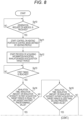
- FIG. 8 is a flowchart showing the example of the process executed by the control unit of the inhalation device according to the present embodiment.
- a program that causes the control unit 116 to execute the series of processes shown in FIG. 8 is stored in the storage portion 114 in advance, for example.
- the control unit 116 waits until the generation request for the aerosol is received (step Sp10: No loop), and starts the control of the heating portion 121 in the control mode defined by the heating profile (step Sp11) when the generation request for the aerosol is received (step Sp10: Yes).
- the control unit 116 starts a process of acquiring information indicating the inhalation mode (that is, the inhalation time, the inhalation amount, or the inhalation intensity described above) in the first acquisition target period A1 and the second acquisition target period A2 (hereinafter, also referred to as an "inhalation mode acquisition process") (step Sp12).
- step Sp12 is executed (that is, the inhalation mode acquisition process is started) as the control based on the heating profile is started. Further, when the first acquisition target period A1 and the second acquisition target period A2 are started from the start of the inhalation-enabled period, step Sp12 is executed (that is, the inhalation mode acquisition process is started) as the inhalation-enabled period is started.
- the inhalation mode acquisition process is a process related to at least one of the inhalation time as described in ⁇ 4-2. Inhalation Time in Acquisition Target Period>, the inhalation amount as described in ⁇ 4-3. Inhalation Amount in Acquisition Target Period>, or the inhalation intensity as described in ⁇ 4-4. Inhalation Intensity in Acquisition Target Period>. These parameters to be acquired by the inhalation mode acquisition process are preset by the manufacturer or the like of the inhalation device 100.
- control unit 116 monitors the presence or absence of the inhalation to the inhalation device 100, and each time the inhalation to the inhalation device 100 is detected, the control unit 116 acquires the inhalation time by the inhalation, the flow rate generated by the inhalation, or the inhalation intensity of the inhalation.
- the control unit 116 compares the maximum value acquired by the inhalation performed so far in the acquisition target period with a value acquired by the current inhalation, and keeps the larger value in the storage portion 114 in advance.
- the control unit 116 when the accumulated value of the inhalation time, the flow rate, or the inhalation intensity by the plurality of inhalations is acquired as the inhalation time, the flow rate, or the inhalation intensity in the acquisition target period, the control unit 116 accumulates a value acquired by the current inhalation to the accumulated value acquired by the inhalation performed so far in the acquisition target period, and keeps an accumulated result in the storage portion 114 in advance. Accordingly, the storage portion 114 can store the inhalation time, the inhalation amount, or the inhalation intensity in the first acquisition target period A1 and the second acquisition target period A2.
- the control unit 116 may store a history of the inhalation time, the flow rate, or the inhalation intensity by the respective inhalations performed to the inhalation device 100 in the storage portion 114 in advance, and may acquire the inhalation time, the flow rate, or the inhalation intensity in the acquisition target period with reference to the history when determining that the first timing ti1 or the second timing ti2 is reached (see steps Sp13 and Sp18).
- control unit 116 waits for the first timing ti1 while executing the inhalation mode acquisition process (step Sp13: No loop), and determines whether the inhalation time, the inhalation amount, or the inhalation intensity in the first acquisition target period A1 is equal to or larger than the first predetermined value Th1 (step Sp14) when the first timing ti1 is reached (step Sp13: Yes).
- step Sp14 when determining that the inhalation time, the inhalation amount, or the inhalation intensity in the first acquisition target period A1 is equal to or larger than the first predetermined value Th1 (step Sp14: Yes), the control unit 116 shortens the second temperature maintenance section S4 (step Sp15), and proceeds to the process in step Sp18.
- control unit 116 determines whether the inhalation time, the inhalation amount, or the inhalation intensity in the first acquisition target period A1 is less than the second predetermined value Th2 (Step Sp16).
- step Sp16 when determining that the inhalation time, the inhalation amount, or the inhalation intensity in the first acquisition target period A1 is less than the second predetermined value Th2 (step Sp16: Yes), the control unit 116 extends the second temperature maintenance section S4 (step Sp17), and proceeds to the process in step Sp18.
- step Sp16 When determining that the inhalation time, the inhalation amount, or the inhalation intensity in the first acquisition target period A1 is not less than the second predetermined value Th2 (step Sp16: No), the control unit 116 proceeds to the process in step Sp18 as it is. In this case, the time length of the second temperature maintenance section S4 is kept at initial tm4 [sec].
- control unit 116 waits for the second timing ti2 while continuously executing the inhalation mode acquisition process (step Sp18: No loop), and ends the inhalation mode acquisition process started in step Sp12 and determines whether the inhalation time, the inhalation amount, or the inhalation intensity in the second acquisition target period A2 is equal to or larger than the third predetermined value Th3 (step Sp19) when the second timing ti2 is reached (step Sp18: Yes).
- step Sp19: Yes when determining that the inhalation time, the inhalation amount, or the inhalation intensity in the second acquisition target period A2 is equal to or larger than the third predetermined value Th3 (step Sp19: Yes), the control unit 116 shortens the third temperature maintenance section S6 (step Sp20) and ends the series of processes shown in FIG. 8 .
- control unit 116 determines whether the inhalation time, the inhalation amount, or the inhalation intensity in the second acquisition target period A2 is less than the fourth predetermined value Th4 (Step Sp21).
- control unit 116 extends the third temperature maintenance section S6 (step Sp22) and ends the series of processes shown in FIG. 8 .
- step Sp21: No When determining that the inhalation time, the inhalation amount, or the inhalation intensity in the second acquisition target period A2 is not less than the fourth predetermined value Th4 (step Sp21: No), the control unit 116 ends the series of processes shown in FIG. 8 as it is. In this case, the time length of the third temperature maintenance section S6 is kept at initial tm6 [sec].
- control unit 116 acquires, based on the detection result of the sensor portion 112 during the first acquisition target period A1 in which the heating portion 121 is controlled in the control mode defined by the heating profile, information indicating the inhalation mode in the first acquisition target period A1. Then, the control unit 116 changes the control mode for the heating portion 121 in a period after the first acquisition target period A1 from the control mode defined by the heating profile to a control mode based on the inhalation mode in the first acquisition target period A1.
- the control unit 116 sets the time length of the second temperature maintenance section S4 to be shorter than tm4 [sec] defined by the heating profile. Accordingly, when it is considered that the consumption amount of the aerosol source and the flavor component in the first acquisition target period A1 is larger than that assumed at the time of designing the heating profile, the second temperature maintenance section S4 is shortened, and the timing at which the heating by the heating portion 121 is stopped can be set to be earlier than that in a case in which the timing is controlled as in the heating profile. Therefore, it is possible to avoid the occurrence of the event that the heating by the heating portion 121 is unnecessarily continued while the aerosol source or flavor component contained in the stick-type substrate 150 is depleting.
- the control unit 116 sets the time length of the third temperature maintenance section S6 to be shorter than tm6 [sec] defined by the heating profile. Accordingly, when it is considered that the consumption amount of the aerosol source and the flavor component in the second acquisition target period A2 is larger than that assumed at the time of designing the heating profile, the third temperature maintenance section S6 is shortened, and the timing at which the heating by the heating portion 121 is stopped can be set to be earlier than that in the case in which the timing is controlled as in the heating profile. Therefore, it is possible to avoid the occurrence of the event that the heating by the heating portion 121 is unnecessarily continued while the aerosol source or flavor component contained in the stick-type substrate 150 is depleting.
- the control unit 116 sets the time length of the second temperature maintenance section S4 to be longer than tm4 [sec] defined by the heating profile. Accordingly, when it is considered that the consumption amount of the aerosol source and the flavor component in the first acquisition target period A1 is smaller than that assumed at the time of designing the heating profile, the second temperature maintenance section S4 is extended, and the period during which the heating by the heating portion 121 is continued (in other words, the period during which the aerosol is generated) can be set to be longer than that in a case in which the period is controlled as in the heating profile. Therefore, it is possible to avoid the occurrence of the event that the heating by the heating portion 121 is stopped while the sufficient aerosol source and flavor component remain in the stick-type substrate 150.
- the control unit 116 sets the time length of the third temperature maintenance section S6 to be longer than tm6 [sec] defined by the heating profile. Accordingly, when it is considered that the consumption amount of the aerosol source and the flavor component in the second acquisition target period A2 is smaller than that assumed at the time of designing the heating profile, the third temperature maintenance section S6 is extended, and the period during which the heating by the heating portion 121 is continued (in other words, the period during which the aerosol is generated) can be set to be longer than that in the case in which the period is controlled as in the heating profile. Therefore, it is possible to avoid the occurrence of the event that the heating by the heating portion 121 is stopped while the sufficient aerosol source and flavor component remain in the stick-type substrate 150.
- the first acquisition target period A1 and the second acquisition target period A2 are provided as the acquisition target period, and the control unit 116 can change the time length of the second temperature maintenance section S4 based on the inhalation time, the inhalation amount, or the inhalation intensity in the first acquisition target period A1 and change the time length of the third temperature maintenance section S6 based on the inhalation time, the inhalation amount, or the inhalation intensity in the second acquisition target period A2, but the present invention is not limited thereto.
- the control unit 116 may change only the time length of the second temperature maintenance section S4 based on the inhalation time, the inhalation amount, or the inhalation intensity in the first acquisition target period A1.
- the control unit 116 may change only the time length of the third temperature maintenance section S6 based on the inhalation time, the inhalation amount, or the inhalation intensity in the first acquisition target period A1.
- only the first acquisition target period A1 may be provided as the acquisition target period, and the control unit 116 may change the time lengths of a second temperature maintenance section S2 and the third temperature maintenance section S6 based on the inhalation time, the inhalation amount, or the inhalation intensity in the first acquisition target period A1.
- only the second acquisition target period A2 may be provided as the acquisition target period, and the control unit 116 may change only the time length of the third temperature maintenance section S6 based on the inhalation time, the inhalation amount, or the inhalation intensity in the second acquisition target period A2.
- the control unit 116 By shortening the acquisition target period as much as possible, for example, by providing only the first acquisition target period A1, it is possible to reduce the burden on the control unit 116 required for the process of acquiring the information indicating the inhalation mode (that is, the inhalation time, the inhalation amount, or the inhalation intensity) in the acquisition target period.
- the information indicating the inhalation mode that is, the inhalation time, the inhalation amount, or the inhalation intensity
- the control unit 116 may execute the process of acquiring the information indicating the inhalation mode in the acquisition target period only in the first half of a period in which the control based on the heating profile is performed. Therefore, in the latter half of the period in which the control based on the heating profile is performed, the control unit 116 can be set not to execute the process of acquiring the information indicating the inhalation mode in the acquisition target period, and the burden related to the process on the control unit 116 can be reduced.
- the number of acquisition target periods may be three or more as in a case in which other acquisition target periods are further provided in addition to the first acquisition target period A1 and the second acquisition target period A2.
- control unit 116 changes the time length of the third temperature maintenance section S6, which is a time section immediately before the stop of the heating by the heating portion 121, according to the inhalation mode in the acquisition target period such as the second acquisition target period A2. Accordingly, until the third temperature maintenance section S6, which is a time section immediately before the stop of the heating by the heating portion 121, is reached, it is possible to generate the aerosol as planned by the heating profile regardless of the inhalation mode of the user (that is, even when the inhalation time, the inhalation amount, or the inhalation intensity in the acquisition target period such as the second acquisition target period A2 is equal to or larger than the predetermined value or is less than the predetermined value).
- a temperature maintenance section in which the temperature of the heating portion 121 is maintained substantially constant such as the second temperature maintenance section S4 and the third temperature maintenance section S6, is set as a time section whose time length is to be changed.
- a time section (for example, the second heating section S5) in which the temperature of the heating portion 121 changes, such as the heating section and the cooling section, may be set as the time section whose time length is to be changed.
- the temperature maintenance section in which the temperature of the heating portion 121 is maintained substantially constant such as the second temperature maintenance section S4 and the third temperature maintenance section S6, is set as the time section whose time length is to be changed, even when the time section is shortened, the event is unlikely to occur that the temperature of the heating portion 121 does not reach the target temperature, or that the temperature of the heating portion 121 rapidly changes. Therefore, by setting the temperature maintenance section as the time section whose time length is to be changed, even when the time length of the time section is changed, it is possible to restrain the occurrence of an event that the quality of the smoking experience of the user may decrease.
- the second temperature maintenance section S4 as the low-temperature section in which the target temperature is relatively low is set as the time section whose time length is to be changed.
- the electric power supplied to the heating portion 121 per unit time is smaller than that in a time section in which the target temperature is relatively high. Therefore, by setting the low-temperature section such as the second temperature maintenance section S4 as the time section whose time length is to be changed, it is possible to extend the time section while restraining an increase in the electric power consumed by the heating portion 121.
- the low-temperature section such as the second temperature maintenance section S4 is typically set to have a certain time length, and room for changing the time length is sufficiently secured, and thus the time length can be easily changed.
- the time length of the subsequent time section is changed based on the inhalation mode in the acquisition target period such as the first acquisition target period A1, but the present invention is not limited thereto.
- the control unit 116 may change the target temperature of the subsequent time section based on the inhalation mode in the acquisition target period such as the first acquisition target period A1.
- control unit 116 changes the target temperature of the subsequent time section based on the inhalation mode in the acquisition target period such as the first acquisition target period A1 will be specifically described.
- the control unit 116 changes the target temperature of the subsequent time section based on the inhalation mode in the acquisition target period such as the first acquisition target period A1.
- FIG. 9 is a diagram (second example thereof) showing the variation of the control mode in the case in which the inhalation time, the inhalation amount, or the inhalation intensity in the first acquisition target period is equal to or larger than the first predetermined value.
- FIG. 10 is a diagram (second example thereof) showing the variation of the control mode in the case in which the inhalation time, the inhalation amount, or the inhalation intensity in the first acquisition target period is less than the second predetermined value.
- the vertical axis in each of FIGS. 9 and 10 represents the target temperature [°C].
- the vertical axis in each of FIGS. 9 and 10 represents the time [sec]. In the examples shown in FIGS. 9 and 10 , it is assumed that only the first acquisition target period A1 is provided as the acquisition target period.
- the control unit 116 changes (that is, increases) the target temperature of the third temperature maintenance section S6 (that is, the sixth time section S6) from initial T3 [°C] to T3a [°C] higher than T3 [°C].
- the constant value ⁇ Ta is preset in the control unit 116 by, for example, the manufacturer or the like of the inhalation device 100.
- the aerosol generated when the stick-type substrate 150 is heated and the flavor component applied to the aerosol depend on a heating temperature and the amounts of the aerosol source and the flavor component remaining in the stick-type substrate 150 at the time of heating. More specifically, the aerosol generated when the stick-type substrate 150 is heated and the flavor component applied to the aerosol increase as the heating temperature becomes higher, and increase as the amounts of the aerosol source and the flavor component remaining in the stick-type substrate 150 at the time of heating increase.
- the inhalation time, the inhalation amount, or the inhalation intensity in the first acquisition target period A1 is equal to or larger than the first predetermined value Th1
- the amounts of the aerosol source and the flavor component remaining in the stick-type substrate 150 are smaller than those assumed at the time of designing the heating profile. Therefore, in such a case, even when the heating is performed at the target temperature defined by the heating profile, there is a possibility that the aerosol or the flavor component applied to the aerosol is insufficient, and the high-quality smoking experience cannot be provided to the user.
- the control unit 116 sets the target temperature of the third temperature maintenance section S6 to be higher than the target temperature defined by the heating profile. Accordingly, it is possible to increase the aerosol generated in the third temperature maintenance section S6 and the flavor component applied to the aerosol as compared with a case in which the control is performed as in the heating profile. Therefore, it is also possible to provide the high-quality smoking experience to the user in the third temperature maintenance section S6.
- the control unit 116 changes (that is, decreases) the target temperature of the third temperature maintenance section S6 (that is, the sixth time section S6) from initial T3 [°C] to T3b [°C] lower than T3 [°C].
- the constant value ⁇ Tb is preset in the control unit 116 by, for example, the manufacturer or the like of the inhalation device 100.
- the inhalation time, the inhalation amount, or the inhalation intensity in the first acquisition target period A1 is less than the second predetermined value Th2
- the amounts of the aerosol source and the flavor component remaining in the stick-type substrate 150 are larger than those assumed at the time of designing the heating profile. Therefore, in such a case, when the heating is performed at the target temperature defined by the heating profile, there is a possibility that the aerosol or the flavor component applied to the aerosol is excessive, and the high-quality smoking experience cannot be provided to the user.
- the control unit 116 sets the target temperature of the third temperature maintenance section S6 to be lower than the target temperature defined by the heating profile. Accordingly, it is possible to decrease the aerosol generated in the third temperature maintenance section S6 and the flavor component applied to the aerosol as compared with the case in which the control is performed as in the heating profile. Therefore, it is also possible to provide the high-quality smoking experience to the user in the third temperature maintenance section S6.
- control unit 116 may change the target temperature of the subsequent time section based on the inhalation mode in the acquisition target period such as the first acquisition target period A1.
- control unit 116 may change both the time length and the target temperature of the subsequent time section based on the inhalation mode in the acquisition target period such as the first acquisition target period A1.
- the control unit 116 may shorten the time length of the third temperature maintenance section S6 to tm6a [sec] described above and increase the target temperature of the third temperature maintenance section S6 to T3a [°C] described above.
- control unit 116 may extend the time length of the third temperature maintenance section S6 to tm6b [sec] described above and decrease the target temperature of the third temperature maintenance section S6 to T3b [°C] described above.
- control unit 116 changes both the time length and the target temperature of the subsequent time section based on the inhalation mode in the acquisition target period such as the first acquisition target period A1, it is possible to appropriately consume the stick-type substrate 150 containing the aerosol source and provide the high-quality smoking experience to the user.
- the inhalation device 100 may have a plurality of heating profiles.
- a "menthol type” substrate in which menthol is contained in the flavor component and a "regular type” substrate in which no menthol is contained in the flavor component as the stick-type substrate 150 it is considered to provide a heating profile for the menthol type substrate and a heating profile for the regular type substrate.
- control unit 116 can determine, for example, the type of the stick-type substrate 150 (that is, the menthol type or the regular type). As an example, the control unit 116 can receive information indicating the type of the stick-type substrate 150 from the user via the input device of the sensor portion 112, and determine the type of the stick-type substrate 150 based on the received information.
- the sensor portion 112 may detect a predetermined physical quantity (for example, transmittance or reflectance of light, the electrical resistance value, or the like) of the stick-type substrate 150 that differs depending on the type. Then, the control unit 116 may determine the type of the stick-type substrate 150 based on the physical quantity detected by the sensor portion 112.
- a predetermined physical quantity for example, transmittance or reflectance of light, the electrical resistance value, or the like
- the control unit 116 selects the heating profile used for the current control of the heating portion 121 from the plurality of heating profiles of the inhalation device 100 based on a determination result of the type of the stick-type substrate 150, and controls the heating portion 121 based on the selected heating profile. For example, the control unit 116 selects the heating profile for the menthol type substrate when determining the type of the stick-type substrate 150 to the menthol type, and selects the heating profile for the regular type substrate when determining the type of the stick-type substrate 150 to the regular type.
- control unit 116 determines the type of the stick-type substrate 150 and selects the heating profile based on the determination result, and thus it is possible to control the heating portion 121 according to the appropriate heating profile corresponding to the type of the stick-type substrate 150. Therefore, it is possible to optimize the flavor experienced by the user and provide the high-quality smoking experience to the user regardless of the type of the stick-type substrate 150.
- the heating profile described in the present embodiment may be the heating profile selected by the control unit 116 based on the determination result of the type of the stick-type substrate 150.
- the acquisition target period may be different for each heating profile.
- the time section in which the time length or the target temperature is changed may be different for each heating profile.
- the change amount of the time length for example, ⁇ ta to ⁇ td described above
- the change amount of the target temperature for example, ⁇ Ta and ⁇ Tb described above
- control unit 116 uses the time length or the target temperature (that is, the control mode) defined by the heating profile as the basis, and then changes the time length or the target temperature based on the inhalation mode in the acquisition target period such as the first acquisition target period A1.
- the control unit 116 sets the time length of the second temperature maintenance section S4 to tm4a [sec] acquired by subtracting the constant value ⁇ ta [sec] from tm4 [sec] defined by the heating profile.
- the control unit 116 sets the time length of the second temperature maintenance section S4 to tm4a [sec] acquired by subtracting the constant value ⁇ ta [sec] from tm4 [sec] defined by the heating profile.
- the control unit 116 sets the target temperature of the third temperature maintenance section S6 to T3a [°C] acquired by adding the constant value ⁇ Ta [°C] to T3 [°C] defined by the heating profile.
- a method may be considered in which a plurality of heating profiles corresponding to inhalation modes different from each other are prepared in the inhalation device 100 in advance, and the control unit 116 appropriately selects the heating profile corresponding to the inhalation mode of the user.
- the plurality of heating profiles are required, and it is also necessary to increase the capacity of the storage portion 114 in order to store the plurality of heating profiles. Therefore, in such a case, the configuration of the inhalation device 100 may be complicated.
- the inhalation device 100 that is capable of providing the high-quality smoking experience to the user by appropriately consuming the stick-type substrate 150 containing the aerosol source even when the inhalation in an inhalation mode different from the standard inhalation as the premise in the heating profile is performed.
- a control method of the inhalation device 100 described in the above embodiment can be achieved by executing a program prepared in advance on a computer (a processor).
- the program is stored in a computer-readable storage medium and is executed by being read from the storage medium.
- the program may be provided in the form of being stored in a non-transitory storage medium such as a flash memory, and may be provided via a network such as the Internet.
- the computer that executes the program can be, for example, a member included in the inhalation device 100 (for example, the CPU of the inhalation device 100), the computer is not limited thereto, and may be a member included in another device (for example, a smartphone or a server device) capable of communicating with the inhalation device 100.
- the control mode for the heating portion in the second period after the first period in which the heating portion is controlled in the control mode defined by the heating profile can be changed to the control mode based on the inhalation mode in the first period. Accordingly, even when the inhalation mode in the first period is different from the standard inhalation as the premise in the heating profile, in the subsequent second period, the heating portion can be appropriately controlled in consideration of the inhalation actually performed in the first period. Therefore, it is possible to appropriately consume the substrate to provide the high-quality smoking experience to the user.
Landscapes
- Thermotherapy And Cooling Therapy Devices (AREA)
- Control Of Temperature (AREA)
Applications Claiming Priority (1)
| Application Number | Priority Date | Filing Date | Title |
|---|---|---|---|
| PCT/JP2022/026839 WO2024009435A1 (ja) | 2022-07-06 | 2022-07-06 | 吸引装置、制御方法、及びプログラム |
Publications (1)
| Publication Number | Publication Date |
|---|---|
| EP4552516A1 true EP4552516A1 (en) | 2025-05-14 |
Family
ID=89453050
Family Applications (1)
| Application Number | Title | Priority Date | Filing Date |
|---|---|---|---|
| EP22950229.9A Pending EP4552516A1 (en) | 2022-07-06 | 2022-07-06 | Inhalation device, control method, and program |
Country Status (6)
| Country | Link |
|---|---|
| US (1) | US20250160431A1 (https=) |
| EP (1) | EP4552516A1 (https=) |
| JP (1) | JPWO2024009435A1 (https=) |
| KR (1) | KR20250020628A (https=) |
| CN (1) | CN119451590A (https=) |
| WO (1) | WO2024009435A1 (https=) |
Family Cites Families (6)
| Publication number | Priority date | Publication date | Assignee | Title |
|---|---|---|---|---|
| TWI608805B (zh) | 2012-12-28 | 2017-12-21 | 菲利浦莫里斯製品股份有限公司 | 加熱型氣溶膠產生裝置及用於產生具有一致性質的氣溶膠之方法 |
| GB201709201D0 (en) * | 2017-06-09 | 2017-07-26 | Nicoventures Holdings Ltd | Electronic aerosol provision system |
| KR102306051B1 (ko) * | 2018-11-16 | 2021-09-28 | 주식회사 케이티앤지 | 에어로졸을 발생 장치 및 에어로졸을 발생 장치의 제어 방법 및 그 장치 |
| CN111053299A (zh) * | 2019-12-31 | 2020-04-24 | 深圳市辰昱科技有限公司 | 一种控制电子烟具的加热温度的方法、装置及电子烟具 |
| WO2022079751A1 (ja) * | 2020-10-12 | 2022-04-21 | 日本たばこ産業株式会社 | 吸引装置、制御方法、及びプログラム |
| CN112841755B (zh) * | 2021-03-09 | 2022-07-19 | 云南中烟工业有限责任公司 | 发热元件加热程序调控方法及提高烟气释放均匀性的方法 |
-
2022
- 2022-07-06 JP JP2024531826A patent/JPWO2024009435A1/ja active Pending
- 2022-07-06 WO PCT/JP2022/026839 patent/WO2024009435A1/ja not_active Ceased
- 2022-07-06 EP EP22950229.9A patent/EP4552516A1/en active Pending
- 2022-07-06 KR KR1020257000393A patent/KR20250020628A/ko active Pending
- 2022-07-06 CN CN202280097656.2A patent/CN119451590A/zh active Pending
-
2025
- 2025-01-03 US US19/008,641 patent/US20250160431A1/en active Pending
Also Published As
| Publication number | Publication date |
|---|---|
| KR20250020628A (ko) | 2025-02-11 |
| CN119451590A (zh) | 2025-02-14 |
| WO2024009435A1 (ja) | 2024-01-11 |
| JPWO2024009435A1 (https=) | 2024-01-11 |
| US20250160431A1 (en) | 2025-05-22 |
Similar Documents
| Publication | Publication Date | Title |
|---|---|---|
| US8511651B2 (en) | Heater unit humidification chamber monitor | |
| EP4353106A1 (en) | Inhalation device, base material, and control method | |
| EP4316290A1 (en) | Inhalation device, control method, and program | |
| EP4552516A1 (en) | Inhalation device, control method, and program | |
| TW202224583A (zh) | 控制方法、吸嚐裝置、終端裝置及程式 | |
| JP7719951B2 (ja) | 情報処理装置、情報処理方法、及びプログラム | |
| EP4434373A1 (en) | Inhalation device | |
| US20250000172A1 (en) | Aerosol generation system, control method, and non-transitory computer readable medium | |
| US20240292905A1 (en) | Inhalation device | |
| EP4420545A1 (en) | System and method | |
| EP4434375A1 (en) | Inhalation device | |
| EP4434374A1 (en) | Suction device | |
| EP4666889A1 (en) | Aerosol generation system and control method | |
| EP4674295A1 (en) | Aerosol generation system, control method, and non-transitory storage medium | |
| EP4613138A1 (en) | Information processing device, inhalation system, and information presentation method | |
| JP7813379B2 (ja) | エアロゾル生成システム、制御方法及びプログラム | |
| EP4559336A1 (en) | Aerosol generation system, control method, and program | |
| EP4563024A1 (en) | Aerosol generation system, control method, and program | |
| EP4427615A1 (en) | Aerosol generation system, control method, and program | |
| EP4666888A1 (en) | Aerosol generation system, control method, and non-transitory recording medium | |
| EP4627952A1 (en) | Terminal device, information processing method, and program | |
| EP4523557A1 (en) | Aerosol generating system and control method | |
| EP4627949A1 (en) | Terminal device and control method | |
| EP4635339A1 (en) | Information processing device, information processing method, and program | |
| CN120322173A (zh) | 用于吸入装置的供电单元、控制方法和控制程序 |
Legal Events
| Date | Code | Title | Description |
|---|---|---|---|
| STAA | Information on the status of an ep patent application or granted ep patent |
Free format text: STATUS: THE INTERNATIONAL PUBLICATION HAS BEEN MADE |
|
| PUAI | Public reference made under article 153(3) epc to a published international application that has entered the european phase |
Free format text: ORIGINAL CODE: 0009012 |
|
| STAA | Information on the status of an ep patent application or granted ep patent |
Free format text: STATUS: REQUEST FOR EXAMINATION WAS MADE |
|
| 17P | Request for examination filed |
Effective date: 20250103 |
|
| AK | Designated contracting states |
Kind code of ref document: A1 Designated state(s): AL AT BE BG CH CY CZ DE DK EE ES FI FR GB GR HR HU IE IS IT LI LT LU LV MC MK MT NL NO PL PT RO RS SE SI SK SM TR |
|
| DAV | Request for validation of the european patent (deleted) | ||
| DAX | Request for extension of the european patent (deleted) |