EP4552467A1 - Machine de travail agricole - Google Patents
Machine de travail agricole Download PDFInfo
- Publication number
- EP4552467A1 EP4552467A1 EP24210476.8A EP24210476A EP4552467A1 EP 4552467 A1 EP4552467 A1 EP 4552467A1 EP 24210476 A EP24210476 A EP 24210476A EP 4552467 A1 EP4552467 A1 EP 4552467A1
- Authority
- EP
- European Patent Office
- Prior art keywords
- machine
- event
- software
- information
- read
- Prior art date
- Legal status (The legal status is an assumption and is not a legal conclusion. Google has not performed a legal analysis and makes no representation as to the accuracy of the status listed.)
- Pending
Links
Images
Classifications
-
- A—HUMAN NECESSITIES
- A01—AGRICULTURE; FORESTRY; ANIMAL HUSBANDRY; HUNTING; TRAPPING; FISHING
- A01D—HARVESTING; MOWING
- A01D41/00—Combines, i.e. harvesters or mowers combined with threshing devices
- A01D41/12—Details of combines
- A01D41/127—Control or measuring arrangements specially adapted for combines
-
- G—PHYSICS
- G07—CHECKING-DEVICES
- G07C—TIME OR ATTENDANCE REGISTERS; REGISTERING OR INDICATING THE WORKING OF MACHINES; GENERATING RANDOM NUMBERS; VOTING OR LOTTERY APPARATUS; ARRANGEMENTS, SYSTEMS OR APPARATUS FOR CHECKING NOT PROVIDED FOR ELSEWHERE
- G07C5/00—Registering or indicating the working of vehicles
- G07C5/08—Registering or indicating performance data other than driving, working, idle, or waiting time, with or without registering driving, working, idle or waiting time
Definitions
- the present invention relates to an agricultural working machine, preferably an agricultural working device.
- Agricultural machines are known for this type of work in agriculture, and a distinction can be made between self-propelled and non-self-propelled machines.
- self-propelled machines are harvesting machines such as combine harvesters, forage harvesters, or farm loaders.
- Non-self-propelled machines can take the form of agricultural implements that can be attached or coupled to a towing vehicle, for example, to a rear power lift.
- a implement can be, for example, a plough, a seed drill, or a sowing machine. Whether an implement is attached or coupled to a towing vehicle can depend on the size of the implement in question.
- This data can be generated by sensors, such as fuel tank levels, and/or by actuators, such as power consumption. Furthermore, this data can be set by the user, such as the machine's driving speed. In addition to these examples, other sources of data and information on machinery are conceivable.
- control units electronic control unit
- ECU electronic control unit
- One object of the present invention is to provide a work machine of the type described above so that the possibilities for data evaluation can be improved. This should apply in particular to "events.” In any case, this should be as simple, cost-effective, space-saving, energy-saving, flexible in use, and/or intuitive as possible. At the very least, an alternative to the known options should be provided.
- the present invention relates to an agricultural working machine of the type described above, preferably as an agricultural working device, with a main control unit, which can also be referred to as ECU and which is designed and configured to operate the agricultural working machine, i.e. to perform or have performed its intended function.
- a main control unit which can also be referred to as ECU and which is designed and configured to operate the agricultural working machine, i.e. to perform or have performed its intended function.
- the main control unit of the work machine always has the above-mentioned machine software as the actual or main operating software, which is supplemented by the service software to provide additional functions, as will be described in more detail below.
- Both software components can be loaded into a common non-volatile memory and/or into separate non-volatile memories of the main control unit, in particular its physical memory component.
- the memory can preferably store the loaded contents persistently, i.e., permanently.
- the software components can be operated on a common, in particular multi-core, processor or on separate processors.
- the ring buffer represents a circular buffer for the continuous storage of current data, whereby older content can always be overwritten by more recent content.
- the oldest data in the ring buffer can be deleted, all other data "moves" one location forward in the ring buffer, and the most recent data is stored in the first location.
- the ring buffer can also store multiple data records with different time priorities. In this case, the oldest data can be directly overwritten by the current data, eliminating the need to move the remaining data.
- the event memory or event memory software represents a data memory in which various events can be stored along with defined additional information related to them, which preferably also includes previous data, which can preferably originate from the ring buffer. Accordingly, an event can have an event data record associated with it, which contains information about the event itself, such as an error, preferably with an error description and/or an error code, as well as additional machine information that may be related to the event or even further or, if possible, all available machine information, in order to be able to take into account machine information when evaluating the result that normally has no connection to the event. This machine information can always be the same, i.e., event-independent, or defined for each event, i.e., event-dependent.
- the information stored in connection with an event can be used, particularly in the case of The event can be loaded from the ring buffer and stored in the event buffer in connection with the event.
- the machine software can capture, process, and/or generate machine information as part of operating the agricultural machine and its sensors and actuators, which can be accessed by the service software without changing this machine information.
- the service software can then access the ring buffer and/or the event buffer to store this information continuously or event-dependently.
- This machine information can be used internally by the machine software and/or the service software and/or transmitted to other internal components. Additionally or alternatively, data can be transmitted to external devices so that this information can be stored, evaluated, and/or displayed there. This can improve the possibilities for data evaluation.
- a further advantage is that such data and information can now also be made available externally so that they can be analyzed there and, in particular, later, i.e. with a time delay, which also enables a chronological representation of the events.
- Updating information or data as data packets can be done by shifting and/or overwriting previous data packets, as described above.
- the updating process can be continuous, cyclical, and/or event-driven, for example, when a predetermined limit value of a sensor is reached.
- the service software is further configured to read the current machine information from the machine software only if an expired cycle time is detected.
- the cycle time describes the regularity with which the ring buffer is updated, or with which the data packets are shifted within the ring buffer and the current packet is added.
- the cycle time can preferably be 10 seconds, although this may depend on the available storage space.
- the external request can be transmitted as information from an external device and processed or responded to by the service software.
- Such an external request can, for example, be created by a person operating or monitoring the agricultural work machine using a mobile device and sent to the agricultural work machine.
- the transmission can preferably be wireless.
- the external storage can, in particular, be a cloud or similar. This allows the stored information to be made available externally for processing, in particular for evaluation, storage, and/or display.
- the data in the event log can be stored chronologically to identify connections between events.
- the work machine has the display unit, wherein the machine software is designed and configured to transmit the read machine information from the event memory to the display unit, and wherein the display unit is designed and configured to display the read machine information from the event memory.
- the display unit can, in particular, be a component of a combined display and operating unit.
- the display unit is configured externally to the work machine, wherein the machine software is configured and configured to transmit the machine information read from the event memory to the display unit.
- the machine software is configured and configured to transmit the machine information read from the event memory to the display unit.
- an external query can be performed, as previously described, to provide the corresponding information to the external display unit.
- the machine information data can be transmitted externally, i.e., externally, to the work machine to be received and displayed there.
- the display unit can, in particular, be a mobile display unit such as a smartphone, a tablet, a laptop, or the like located in the vicinity of the work machine, wherein data transmission can occur via Bluetooth, Wi-Fi, or the like.
- the external display unit can also be a laptop or desktop computer located remotely from the work machine, and data transmission can occur via Wi-Fi and/or a wired connection.
- the current machine information and/or the event-relevant machine information include operating states, sensor values, machine status, machine configurations, and/or machine settings of the work machine and/or individual components of the work machine. This allows the corresponding information to be used as described above.
- the event-relevant machine information comprises past information from the ring buffer.
- This allows past information about the event, which can be buffered by the ring buffer for a sufficient length of time to allow for a look back in time to the event, to be recorded, stored, and taken into account for evaluating the cause of the event. This can, for example, facilitate or improve the determination of the cause in the event of an error.
- the past time period can be predetermined; this can be general, i.e., it can be valid for every event, or it can vary depending on the event. If necessary, several events can cover the same past time period, while the remaining events can be individual.
- the ring buffer can be accessed accordingly to retrieve the temporarily stored or temporally buffered machine information from it, either at the respective time scale or for the respective past period.
- the history that can be accessed in the ring buffer can be limited by its size or by the information contained therein.
- the event-relevant machine information includes absolute and/or relative time information. This allows additional Information about an absolute and/or relative time of the event is recorded, stored and taken into account to evaluate the cause of the event, which can, for example, facilitate or improve the determination of the cause of an error by allowing the occurrence of the error or certain information related to the error to be assigned to one another in time and/or absolutely.
- an event comprises an error and/or a warning of the work machine and/or individual components of the work machine. This can represent concrete implementation possibilities.
- the present invention further relates to a computer-readable (storage) medium on which the service software is stored as described above. This makes it possible to provide service software according to the invention.
- all available data and information of a work machine can be stored continuously and/or cyclically in order to make them persistent, i.e., permanently, available for future analysis.
- data and information can be stored continuously and/or cyclically.
- data and information can be specifically stored for an "event," which were preferably defined in advance as belonging to this event.
- the events can be displayed in chorological order. The display can be done either on a display unit on the work machine or, additionally or alternatively, via remote access.
- a ring buffer can be provided here.
- the ring buffer can enable remanent and/or persistent storage of operating states such as sensor values, machine status, machine configurations, machine settings, and the like. Additionally or alternatively, storage in a ring buffer of the working machine can be enabled. Additionally or alternatively, transfer to and storage on an external storage medium such as a cloud, database, USB stick, and the like can be performed. Additionally or alternatively, persistent storage of all data can be provided, i.e., a ring buffer can be provided within an external storage medium so that this information can be stored there permanently. This can include historical storage in chronological order with an absolute and/or relative time stamp. Additionally or alternatively, all or individual data from the ring buffer can be read out from the machine's area logic for subsequent analysis. Additionally or alternatively, all or individual data from the ring buffer can be displayed from the machine's area logic for analysis.
- event monitoring can be provided additionally or alternatively. This enables remanent storage, i.e., storage that can be restored even after the data has been deleted or after a system failure, of events such as errors, warnings, and the like that occur during machine operation. Additionally or alternatively, all operating states relevant to the aforementioned event can be saved, such as sensor values, machine status, machine configurations, machine settings, and the like. Additionally or alternatively, all saved operating states of the event can be summarized in an associated data packet and provided with an absolute and/or relative timestamp. Additionally or alternatively, transfer to and storage on an external storage medium such as a cloud, a database, a USB stick, and the like can be performed.
- an external storage medium such as a cloud, a database, a USB stick, and the like can be performed.
- persistent storage of the data packets can be performed, for example, historical storage in chronological order with an absolute and/or relative timestamp. Additionally or alternatively, all or individual data from the data packets can be read from the machine's area logic for subsequent analysis. Additionally or alternatively, all or individual data from the data packets can be displayed from the machine's area logic for analysis.
- a so-called quick check can also be performed. This involves a chronological presentation or display of the events that have occurred on a work machine. This can be done either on a display unit on the work machine or via remote access.
- the remanently stored operating states of the area logic can be made available for external analysis.
- the externally performed analysis of the remanently stored operating states can be displayed in the area logic and/or via the web interface.
- event-related data packets and/or the data packets from the ring buffer of the operating states can be transmitted to an external data storage device for remanent storage via a bus system, for example, CAN bus and/or Ethernet.
- the event-related data packets and/or the data packets from the ring buffer of the operating states can also be transmitted to an external data storage device for remanent storage via a wireless connection.
- data and information from a working machine can be made available for later and possibly external analysis outside of the working machine.
- the data and information from the past can be used to draw conclusions about the underlying cause of the event.
- Event-related and thus context-related data packages can be made available.
- a chronological representation of the events of a working machine can be enabled (quick check). The historical progression of the machine and component states can be tracked over the service life of the working machine and its components.
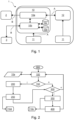
- a working machine 1 according to the invention according to the Figure 1 can be, for example, a non-self-propelled agricultural working machine 1 in the form of an attached or trailed working device 1 such as a plough, a seed drill or a sowing machine.
- the work machine 1 has a main control unit 10, on which, during operation, a machine software 10a, a service software 10b, a ring buffer 10c, and an event memory 10d run as software or as computer programs.
- the work machine 1 has several machine sensors/actuators 11, which are operated either directly by the machine software 10a or indirectly by the machine software 10a via a respective sub-control unit 12.
- wired data connections A are Form of wired data buses A is used, which can be implemented, for example, using a CAN bus A.
- An external display unit 2 is provided, which is implemented as a display/operating unit 2.
- a smartphone, a tablet, or a laptop for example, can be used to allow a person to accompany and monitor the work machine 1 during operation or, in the event of an event, in particular a fault, to carry out on-site analysis and troubleshooting.
- a wireless data connection B in the form of a wireless data bus B can be used, which can be implemented, for example, using WLAN or Bluetooth.
- the work machine 1 can also be connected to the Internet via a wireless data connection B, for example in the form of a mobile phone or WLAN connection, in order to be able to store data on an external storage device 3, such as in a cloud 3.
- a wireless data connection B for example in the form of a mobile phone or WLAN connection, in order to be able to store data on an external storage device 3, such as in a cloud 3.
- the main control unit 10 is designed and configured to process the computer programs of the machine software 10a, the service software 10b, the ring buffer 10c, and the event buffer 10d during operation.
- the machine software 10a can be used to operate the work machine 1.
- the service software 10b can be used to access machine information from the machine software 10a.
- the ring buffer 10c can be used to continuously or cyclically store current machine information from the machine software 10a.
- the event buffer 10d can be used to store event-relevant machine information from the machine software 10a.
- the service software 10b is configured to read current machine information from the machine software 10a, store the read current machine information from the machine software 10a in the ring buffer 10c, and update the ring buffer 10c, which can be done by overwriting the oldest data with the most recent data. To do this, the oldest data in the ring buffer is deleted, all remaining data packets are shifted one space forward in the ring buffer, and the most recent data is stored in the first space of the ring buffer.
- the service software 10b is further configured to read the current machine information from the machine software 10a only if an expired cycle time is detected.
- the cycle time describes the regularity with which the ring buffer is updated, or the packets are moved within the ring buffer and the current packet is added.
- the cycle time can be 10 seconds, meaning that the current machine information can be read from the machine software 10a every 10 seconds.
- the service software 10b is further configured to monitor an external query of the ring buffer 10c, which is made, for example, by a person via a mobile terminal as part of the monitoring of the work machine 1 via a wireless data connection A, in the case of an external query of the ring buffer 10c, to read out the current machine information of the machine software 10a from the ring buffer 10c and to send the read machine information of the ring buffer 10c to an external memory 3 via the wireless data connection A.
- the service software 10b is further configured to monitor the operation of the work machine 1 for events such as errors or error messages, the exceeding and/or falling below of predetermined limit values by predetermined parameters of the work machine or its components and the like, to read out the event-relevant machine information of the machine software 10a in the event of an event and to store the event-relevant machine information of the machine software 10a in the event memory 10d.
- events such as errors or error messages, the exceeding and/or falling below of predetermined limit values by predetermined parameters of the work machine or its components and the like, to read out the event-relevant machine information of the machine software 10a in the event of an event and to store the event-relevant machine information of the machine software 10a in the event memory 10d.
- the service software 10b is further configured to monitor an external query, as previously described, of the event memory 10d, to read the event-relevant machine information of the machine software 10a from the event memory 10d in the event of an external query, and to send the read machine information of the event memory 10d to an external memory 3.
- the service software 10b is further configured to monitor the display unit 2, to read the event-relevant machine information from the event memory 10d in the event of a query, and to transmit the read machine information from the event memory 10d to the machine software 10a.
- the machine software 10a is configured and set up to transmit the read machine information from the event memory 10d to the display unit 2, so that the read machine information from the event memory 10d can be displayed or represented by the display unit 2.
- the work machine 1 it is possible for the work machine 1 to have the display unit, wherein the machine software 10a is designed and configured to transmit the read-out machine information of the event memory 10d to the display unit, and wherein the display unit is designed and configured to display the read-out machine information of the event memory 10d.
- the current machine information and/or the event-relevant machine information include operating states, sensor values, machine status, machine configurations and/or machine settings of the work machine 1 and/or individual components of the work machine 1 such as its machine sensors/actuators 11.
- the event-relevant machine information comprise at least partially past information from the ring buffer 10c.
- the event-relevant machine information comprises absolute and/or relative time information, for example, a specific time and/or a relative time interval or a time period relative to a specific point in time, and the like.
- An event comprises an error and/or a warning from the work machine 1 and/or individual components of the work machine 1, such as its machine sensors/actuators 11.
- FIG. 1 a schematic flow diagram of a method according to the invention for storing data.
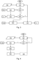
- Figure 3 shows a schematic flow diagram for sending data.
- Figure 4 shows a schematic flowchart for displaying data.
- a start 000 of the procedure ( Fig. 2 ) is followed by operation 100 of the working machine 1 by means of the machine software 10a. This is followed by monitoring 150 the operation of the working machine 1 for events such as, for example, an error message.
- events such as, for example, an error message.
- the event-relevant machine information from the machine software 10a is read out 200 and the event-relevant machine information from the machine software 10a is stored 250 in the event memory 10d.
- the cycle time is monitored 300 or queried. If the cycle time has expired, the current machine information from the machine software 10a is saved 350 in the ring buffer 10c, and the ring buffer 10c is updated 400, see. Figure 2 .
- a monitoring 450 of the external query of the ring buffer 10c If an external query of the ring buffer 10c occurs, a reading 500 of current machine information of the machine software 10a from the ring buffer 10c and a Sending 550 of the read machine information from the ring buffer 10c to an external memory 3.
- the external query of the event memory 10d is monitored 600. If an external query of the event memory 10d occurs, the event-relevant machine information is read 650 from the event memory 10d, and the read machine information of the event memory 10d is sent 700 to an external memory 3, see. Figure 3 .
- the Fig. 4 monitoring 750 of the external display unit 2. If an external query of the event memory 10d occurs, for example, by a request from a person using an external display/operating unit 2, the event-relevant machine information is read out 650 from the event memory 10d, the read-out machine information of the event memory 10d is transmitted 800 to machine software 10a, the read-out machine information of the event memory 10d is transmitted 850 to the external display unit 2, and the read-out machine information of the event memory 10d is displayed 900 by means of the display unit 2.
- an external query of the event memory 10d occurs, for example, by a request from a person using an external display/operating unit 2
- the event-relevant machine information is read out 650 from the event memory 10d
- the read-out machine information of the event memory 10d is transmitted 800 to machine software 10a
- the read-out machine information of the event memory 10d is transmitted 850 to the external display unit 2
- the read-out machine information of the event memory 10d is displayed 900 by means of the display unit 2.
Landscapes
- Physics & Mathematics (AREA)
- General Physics & Mathematics (AREA)
- Life Sciences & Earth Sciences (AREA)
- Environmental Sciences (AREA)
- Testing And Monitoring For Control Systems (AREA)
Applications Claiming Priority (1)
| Application Number | Priority Date | Filing Date | Title |
|---|---|---|---|
| DE102023131365.7A DE102023131365A1 (de) | 2023-11-10 | 2023-11-10 | Landwirtschaftliche Arbeitsmaschine |
Publications (1)
| Publication Number | Publication Date |
|---|---|
| EP4552467A1 true EP4552467A1 (fr) | 2025-05-14 |
Family
ID=93378935
Family Applications (1)
| Application Number | Title | Priority Date | Filing Date |
|---|---|---|---|
| EP24210476.8A Pending EP4552467A1 (fr) | 2023-11-10 | 2024-11-04 | Machine de travail agricole |
Country Status (2)
| Country | Link |
|---|---|
| EP (1) | EP4552467A1 (fr) |
| DE (1) | DE102023131365A1 (fr) |
Citations (5)
| Publication number | Priority date | Publication date | Assignee | Title |
|---|---|---|---|---|
| WO2009103387A1 (fr) * | 2008-02-22 | 2009-08-27 | Daimler Ag | Procédé d’enregistrement de données de diagnostic dans un véhicule automobile au moyen d’une mémoire en anneau volatile, suivi d’une réduction des données dans une mémoire non volatile |
| EP3208775A1 (fr) * | 2016-02-18 | 2017-08-23 | Deutsche Telekom AG | Enregistrement de données de fonctionnement dans un véhicule automobile |
| EP3626041A1 (fr) * | 2018-09-24 | 2020-03-25 | CLAAS Tractor S.A.S. | Système de travail agricole |
| US20210267117A1 (en) * | 2020-02-21 | 2021-09-02 | The Climate Corporation | Flagging operational differences in agricultural implements |
| EP4220530A1 (fr) * | 2022-01-27 | 2023-08-02 | CLAAS E-Systems GmbH | Procédé d'aide à la classification de données d'environnement d'une machine de travail agricole |
Family Cites Families (1)
| Publication number | Priority date | Publication date | Assignee | Title |
|---|---|---|---|---|
| DE102015200269A1 (de) * | 2015-01-12 | 2016-07-14 | Schaeffler Technologies AG & Co. KG | Verfahren und System für die Erfassung von Fahrzeugereignissen |
-
2023
- 2023-11-10 DE DE102023131365.7A patent/DE102023131365A1/de active Pending
-
2024
- 2024-11-04 EP EP24210476.8A patent/EP4552467A1/fr active Pending
Patent Citations (5)
| Publication number | Priority date | Publication date | Assignee | Title |
|---|---|---|---|---|
| WO2009103387A1 (fr) * | 2008-02-22 | 2009-08-27 | Daimler Ag | Procédé d’enregistrement de données de diagnostic dans un véhicule automobile au moyen d’une mémoire en anneau volatile, suivi d’une réduction des données dans une mémoire non volatile |
| EP3208775A1 (fr) * | 2016-02-18 | 2017-08-23 | Deutsche Telekom AG | Enregistrement de données de fonctionnement dans un véhicule automobile |
| EP3626041A1 (fr) * | 2018-09-24 | 2020-03-25 | CLAAS Tractor S.A.S. | Système de travail agricole |
| US20210267117A1 (en) * | 2020-02-21 | 2021-09-02 | The Climate Corporation | Flagging operational differences in agricultural implements |
| EP4220530A1 (fr) * | 2022-01-27 | 2023-08-02 | CLAAS E-Systems GmbH | Procédé d'aide à la classification de données d'environnement d'une machine de travail agricole |
Also Published As
| Publication number | Publication date |
|---|---|
| DE102023131365A1 (de) | 2025-05-15 |
Similar Documents
| Publication | Publication Date | Title |
|---|---|---|
| EP1506533B1 (fr) | Procede de transmission de donnees de vehicule | |
| EP2702846B1 (fr) | Dispositif de télémétrie | |
| DE102008010628A1 (de) | Verfahren zum Erfassen von Diagnosedaten in einem Kraftfahrzeug mittels eines flüchtigen Ringspeichers und anschließender Datenreduktion in einen nichtflüchtigen Speicher | |
| DE102010061490A1 (de) | Vorrichtung zum Informieren einer Zielvorrichtung über Fehlfunktionen, die bei der Kommunikation mit einer Quellvorrichtung auftreten, sowie System, in dem eine solche Vorrichtung eingebunden ist | |
| EP3516519B1 (fr) | Chien de garde destiné à la surveillance d'un processeur | |
| EP4552467A1 (fr) | Machine de travail agricole | |
| DE102008038501A1 (de) | Verfahren zum Bestimmen einer statischen Datenstruktur eines Feldgerätes | |
| DE102015223968B4 (de) | Elektronische Radeinheit für ein Fahrzeugrad, elektronische Einrichtung für ein Fahrzeug, sowie Betriebsverfahren hierfür | |
| EP2877902B1 (fr) | Procédé pour le maintien en état de l'aptitude au fonctionnement d'un appareil de champ | |
| EP2073136B1 (fr) | Système et procédé destinés à la production de données d'évaluation | |
| EP1119801B1 (fr) | Procede d'exploitation d'un systeme d'automatisation | |
| DE102009027168B4 (de) | Verfahren zum Ermitteln einer übermittelten Telegramm-Datenlänge | |
| EP3522557B1 (fr) | Procédé d'échange télémétrique de données entre au moins un engin de travail agricole et un calculateur pilote ainsi qu'engin de travail agricole correspondant | |
| DE102004060007A1 (de) | Datenbussystem für Kraftfahrzeuge und Diagnoseverfahren | |
| EP1870787B1 (fr) | Méthode de surveillance d'un programme cyclique de commande | |
| DE102009047974B4 (de) | Verfahren zur Programmierung eines Steuergeräts | |
| DE112016006217T5 (de) | Programmierbare Anzeigevorrichtung | |
| EP2498155B1 (fr) | Procédé de reconnaissance de modifications d'interfaces software et d'adaptation automatique de ces interfaces dans un programme d'automatisation | |
| WO2016112902A1 (fr) | Procédé et système pour la détection d'événements de véhicule | |
| DE102006016016B4 (de) | Fehlerdiagnosesystem und Verfahren zur Analyse und Anzeige von Fehlern zumindest eines Steuergeräts in einem Fahrzeug | |
| EP1117023A2 (fr) | Dispositif de diagnostic de fautes pendant le fonctionnement d'un véhicule automobile | |
| DE102023124394A1 (de) | Verfahren zum Aufbau einer Menüseite auf einem Host mit einem Display | |
| DE112021000872T5 (de) | Steuersystem | |
| DE202018000385U1 (de) | Vorrichtung zur Bereitstellung von Maschinendaten | |
| DE112022007190T5 (de) | Steuervorrichtung, Steuerverfahren und Programm |
Legal Events
| Date | Code | Title | Description |
|---|---|---|---|
| PUAI | Public reference made under article 153(3) epc to a published international application that has entered the european phase |
Free format text: ORIGINAL CODE: 0009012 |
|
| STAA | Information on the status of an ep patent application or granted ep patent |
Free format text: STATUS: THE APPLICATION HAS BEEN PUBLISHED |
|
| AK | Designated contracting states |
Kind code of ref document: A1 Designated state(s): AL AT BE BG CH CY CZ DE DK EE ES FI FR GB GR HR HU IE IS IT LI LT LU LV MC ME MK MT NL NO PL PT RO RS SE SI SK SM TR |
|
| STAA | Information on the status of an ep patent application or granted ep patent |
Free format text: STATUS: REQUEST FOR EXAMINATION WAS MADE |
|
| 17P | Request for examination filed |
Effective date: 20251114 |