EP4550523A1 - Power battery heat exchanger, power battery system and electric vehicle - Google Patents
Power battery heat exchanger, power battery system and electric vehicle Download PDFInfo
- Publication number
- EP4550523A1 EP4550523A1 EP23830369.7A EP23830369A EP4550523A1 EP 4550523 A1 EP4550523 A1 EP 4550523A1 EP 23830369 A EP23830369 A EP 23830369A EP 4550523 A1 EP4550523 A1 EP 4550523A1
- Authority
- EP
- European Patent Office
- Prior art keywords
- collecting tube
- power battery
- harmonica
- tubes
- heat exchanger
- Prior art date
- Legal status (The legal status is an assumption and is not a legal conclusion. Google has not performed a legal analysis and makes no representation as to the accuracy of the status listed.)
- Pending
Links
Images



Classifications
-
- B—PERFORMING OPERATIONS; TRANSPORTING
- B60—VEHICLES IN GENERAL
- B60L—PROPULSION OF ELECTRICALLY-PROPELLED VEHICLES; SUPPLYING ELECTRIC POWER FOR AUXILIARY EQUIPMENT OF ELECTRICALLY-PROPELLED VEHICLES; ELECTRODYNAMIC BRAKE SYSTEMS FOR VEHICLES IN GENERAL; MAGNETIC SUSPENSION OR LEVITATION FOR VEHICLES; MONITORING OPERATING VARIABLES OF ELECTRICALLY-PROPELLED VEHICLES; ELECTRIC SAFETY DEVICES FOR ELECTRICALLY-PROPELLED VEHICLES
- B60L58/00—Methods or circuit arrangements for monitoring or controlling batteries or fuel cells, specially adapted for electric vehicles
- B60L58/10—Methods or circuit arrangements for monitoring or controlling batteries or fuel cells, specially adapted for electric vehicles for monitoring or controlling batteries
- B60L58/24—Methods or circuit arrangements for monitoring or controlling batteries or fuel cells, specially adapted for electric vehicles for monitoring or controlling batteries for controlling the temperature of batteries
- B60L58/26—Methods or circuit arrangements for monitoring or controlling batteries or fuel cells, specially adapted for electric vehicles for monitoring or controlling batteries for controlling the temperature of batteries by cooling
-
- H—ELECTRICITY
- H01—ELECTRIC ELEMENTS
- H01M—PROCESSES OR MEANS, e.g. BATTERIES, FOR THE DIRECT CONVERSION OF CHEMICAL ENERGY INTO ELECTRICAL ENERGY
- H01M10/00—Secondary cells; Manufacture thereof
- H01M10/60—Heating or cooling; Temperature control
- H01M10/61—Types of temperature control
- H01M10/613—Cooling or keeping cold
-
- H—ELECTRICITY
- H01—ELECTRIC ELEMENTS
- H01M—PROCESSES OR MEANS, e.g. BATTERIES, FOR THE DIRECT CONVERSION OF CHEMICAL ENERGY INTO ELECTRICAL ENERGY
- H01M10/00—Secondary cells; Manufacture thereof
- H01M10/60—Heating or cooling; Temperature control
- H01M10/61—Types of temperature control
- H01M10/615—Heating or keeping warm
-
- H—ELECTRICITY
- H01—ELECTRIC ELEMENTS
- H01M—PROCESSES OR MEANS, e.g. BATTERIES, FOR THE DIRECT CONVERSION OF CHEMICAL ENERGY INTO ELECTRICAL ENERGY
- H01M10/00—Secondary cells; Manufacture thereof
- H01M10/60—Heating or cooling; Temperature control
- H01M10/61—Types of temperature control
- H01M10/617—Types of temperature control for achieving uniformity or desired distribution of temperature
-
- H—ELECTRICITY
- H01—ELECTRIC ELEMENTS
- H01M—PROCESSES OR MEANS, e.g. BATTERIES, FOR THE DIRECT CONVERSION OF CHEMICAL ENERGY INTO ELECTRICAL ENERGY
- H01M10/00—Secondary cells; Manufacture thereof
- H01M10/60—Heating or cooling; Temperature control
- H01M10/62—Heating or cooling; Temperature control specially adapted for specific applications
- H01M10/625—Vehicles
-
- H—ELECTRICITY
- H01—ELECTRIC ELEMENTS
- H01M—PROCESSES OR MEANS, e.g. BATTERIES, FOR THE DIRECT CONVERSION OF CHEMICAL ENERGY INTO ELECTRICAL ENERGY
- H01M10/00—Secondary cells; Manufacture thereof
- H01M10/60—Heating or cooling; Temperature control
- H01M10/65—Means for temperature control structurally associated with the cells
- H01M10/655—Solid structures for heat exchange or heat conduction
- H01M10/6554—Rods or plates
-
- H—ELECTRICITY
- H01—ELECTRIC ELEMENTS
- H01M—PROCESSES OR MEANS, e.g. BATTERIES, FOR THE DIRECT CONVERSION OF CHEMICAL ENERGY INTO ELECTRICAL ENERGY
- H01M10/00—Secondary cells; Manufacture thereof
- H01M10/60—Heating or cooling; Temperature control
- H01M10/65—Means for temperature control structurally associated with the cells
- H01M10/655—Solid structures for heat exchange or heat conduction
- H01M10/6556—Solid parts with flow channel passages or pipes for heat exchange
-
- H—ELECTRICITY
- H01—ELECTRIC ELEMENTS
- H01M—PROCESSES OR MEANS, e.g. BATTERIES, FOR THE DIRECT CONVERSION OF CHEMICAL ENERGY INTO ELECTRICAL ENERGY
- H01M10/00—Secondary cells; Manufacture thereof
- H01M10/60—Heating or cooling; Temperature control
- H01M10/65—Means for temperature control structurally associated with the cells
- H01M10/656—Means for temperature control structurally associated with the cells characterised by the type of heat-exchange fluid
- H01M10/6567—Liquids
-
- H—ELECTRICITY
- H01—ELECTRIC ELEMENTS
- H01M—PROCESSES OR MEANS, e.g. BATTERIES, FOR THE DIRECT CONVERSION OF CHEMICAL ENERGY INTO ELECTRICAL ENERGY
- H01M10/00—Secondary cells; Manufacture thereof
- H01M10/60—Heating or cooling; Temperature control
- H01M10/65—Means for temperature control structurally associated with the cells
- H01M10/656—Means for temperature control structurally associated with the cells characterised by the type of heat-exchange fluid
- H01M10/6567—Liquids
- H01M10/6568—Liquids characterised by flow circuits, e.g. loops, located externally to the cells or cell casings
-
- H—ELECTRICITY
- H01—ELECTRIC ELEMENTS
- H01M—PROCESSES OR MEANS, e.g. BATTERIES, FOR THE DIRECT CONVERSION OF CHEMICAL ENERGY INTO ELECTRICAL ENERGY
- H01M10/00—Secondary cells; Manufacture thereof
- H01M10/60—Heating or cooling; Temperature control
- H01M10/66—Heat-exchange relationships between the cells and other systems, e.g. central heating systems or fuel cells
- H01M10/663—Heat-exchange relationships between the cells and other systems, e.g. central heating systems or fuel cells the system being an air-conditioner or an engine
-
- H—ELECTRICITY
- H01—ELECTRIC ELEMENTS
- H01M—PROCESSES OR MEANS, e.g. BATTERIES, FOR THE DIRECT CONVERSION OF CHEMICAL ENERGY INTO ELECTRICAL ENERGY
- H01M2220/00—Batteries for particular applications
- H01M2220/20—Batteries in motive systems, e.g. vehicle, ship, plane
-
- Y—GENERAL TAGGING OF NEW TECHNOLOGICAL DEVELOPMENTS; GENERAL TAGGING OF CROSS-SECTIONAL TECHNOLOGIES SPANNING OVER SEVERAL SECTIONS OF THE IPC; TECHNICAL SUBJECTS COVERED BY FORMER USPC CROSS-REFERENCE ART COLLECTIONS [XRACs] AND DIGESTS
- Y02—TECHNOLOGIES OR APPLICATIONS FOR MITIGATION OR ADAPTATION AGAINST CLIMATE CHANGE
- Y02E—REDUCTION OF GREENHOUSE GAS [GHG] EMISSIONS, RELATED TO ENERGY GENERATION, TRANSMISSION OR DISTRIBUTION
- Y02E60/00—Enabling technologies; Technologies with a potential or indirect contribution to GHG emissions mitigation
- Y02E60/10—Energy storage using batteries
Definitions
- the present disclosure relates to the field of power battery technologies, and specifically, to a power battery heat exchanger, a power battery system, and an electric vehicle.
- a collecting tube assembly of a heat exchanger for direct cooling of a power battery is usually formed by a number of round tubes and three-channel tubes.
- the collecting tube assembly generally does not heat or cool a battery system, causing heat or cold loss and reducing heat exchange efficiency of the heat exchanger.
- An objective of the present disclosure is to provide a power battery heat exchanger, a power battery system, and an electric vehicle.
- the power battery heat exchanger arranges a first collecting tube and a second collecting tube as a first collecting tube assembly. In this way, a quantity of lines of the first collecting tube assembly is reduced, which has high space utilization, reduces ineffective heat exchange, improves heat exchange efficiency of the heat exchanger, and reduces material costs.
- a power battery heat exchanger includes:
- the first direction is perpendicular to the second direction.
- At least two outermost harmonica tubes are in communication with the first collecting tube.
- a quantity of harmonica tubes is an even number, and a quantity of harmonica tubes connected to the first collecting tube is equal to a quantity of harmonica tubes connected to the second collecting tube.
- the quantity of harmonica tubes is eight, in the second direction, four innermost harmonica tubes are respectively in communication with the second collecting tube, and other four harmonica tubes are respectively in communication with the first collecting tube.
- the quantity of harmonica tubes is eight, in the second direction, two outermost harmonica tubes and two innermost harmonica tubes are respectively in communication with the first collecting tube, and other four harmonica tubes are respectively in communication with the second collecting tube.
- the second collecting tube assembly includes a third collecting tube and a fourth collecting tube;
- the third collecting tube is in communication with second ends of four adjacently arranged harmonica tubes; and the fourth collecting tube is in communication with second ends of other four adjacently arranged harmonica tubes.
- the power battery heat exchanger further includes a vapor chamber arranged on a side of the number of harmonica tubes, and the number of harmonica tubes are fixedly connected to the vapor chamber.
- the first collecting tube is provided with a number of first strip holes extending in a length direction of the first collecting tube, and the harmonica tube is fixedly connected to the first strip hole, to cause a number of flow channels of the harmonica tube to be in communication with the first collecting tube; and/or the second collecting tube is provided with a number of second strip holes extending in a length direction of the second collecting tube, and the harmonica tube is fixedly connected to the second strip hole, to cause the number of flow channels of the harmonica tube to be in communication with the second collecting tube.
- the connector includes a liquid inlet in communication with the inlet and a liquid outlet in communication with the outlet, the liquid inlet is in communication with the first collecting tube through a first connection tube, and the liquid outlet is in communication with the second collecting tube through a second connection tube.
- a power battery system is further provided and includes a power battery.
- the power battery system further includes the foregoing power battery heat exchanger.
- the power battery heat exchanger is arranged on a surface of the power battery and is configured to heat and/or cool the power battery.
- an electric vehicle is further provided.
- the electric vehicle includes the foregoing power battery system.
- the first collecting tube assembly is arranged as the first collecting tube and the second collecting tube, and the first collecting tube and the second collecting tube are respectively in communication with the inlet and the outlet of the connector.
- a refrigerant entering through the inlet directly enters some harmonica tubes after passing through the first collecting tube, is combined by the second collecting tube assembly and flows into remaining harmonica tubes, and finally passes through the second collecting tube and flows out through the outlet of the connector to form a circuit.
- the number of harmonica tubes exchange heat for the power battery through the vapor chamber, to heat or cool the power battery.
- the first collecting tube assembly includes only the first collecting tube and the second collecting tube. In this way, a quantity of lines of the first collecting tube assembly is reduced as a whole, space utilization is improved, ineffective heat exchange is reduced, heat exchange efficiency of the heat exchanger is improved, and material costs are reduced.
- orientation words such as “up, down, left, and right", generally refer to up, down, left, and right of the accompanying drawing; “inner and outer” refer to “inner and outer” with respect to an outline of a corresponding component; “X” refers to a first direction; and “Y” refers to a second direction.
- terms “first”, “second”, “third”, “fourth”, and the like used in the present disclosure are to distinguish one element from another element, and do not have order and importance.
- the same reference numerals in different accompanying drawings represent the same or similar elements. The foregoing definitions are merely used to explain and illustrate the present disclosure, and are not to be construed as a limitation on the present disclosure.
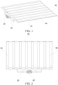
- FIG. 1 and FIG. 2 a heat exchanger for direct cooling of a power battery is shown in FIG. 1 and FIG. 2 .
- the heat exchanger is mainly formed by welding a harmonica tube 10, a collecting tube assembly 20, a tail end collecting tube 30, a connector 40, and a vapor chamber 50.
- the connector 40 is connected to an air conditioning system of a whole vehicle.
- the connector 40, the collecting tube assembly 20, the tail end collecting tube 30, and the harmonica tube 10 are welded together to form the heat exchanger with a flow channel inside.
- the vapor chamber 50 is welded and fixed to the harmonica tube 10.
- the heat exchanger is connected to the whole vehicle through a two-hole connector, and the harmonica tube is used as a component that exchanges heat with a battery in the entire heat exchanger.
- the harmonica tube covers the power battery. Therefore, a connection between the connector and the harmonica tube needs to be transitioned through a collecting tube assembly.
- the collecting tube assembly 20 of the heat exchanger is formed by nine round tubes and two three-channel tubes. In addition, the collecting tube assembly cannot be in direct contact with the battery, and cannot heat or cool a battery system, causing heat or cold loss and reducing heat exchange efficiency of the heat exchanger.
- a power battery heat exchanger 1000 includes a connector 400, a vapor chamber 500, a first collecting tube assembly 200 and a second collecting tube assembly 300 arranged spaced away in a first direction X, and a number of harmonica tubes 100 arranged between the first collecting tube assembly 200 and the second collecting tube assembly 300 and arranged at intervals in a second direction Y.
- the number of harmonica tubes 100 are connected to the vapor chamber 500.
- the first direction X is perpendicular to the second direction Y.
- the harmonica tube 100 includes a first end 101 and a second end 102 that are opposite to each other.
- the first collecting tube assembly 200 includes a first collecting tube 210 and a second collecting tube 220.
- the connector 400 includes an inlet 401 and an outlet 402.
- the inlet 401 of the connector 400 is respectively in communication with first ends 101 of some harmonica tubes 100 through the first collecting tube 210.
- the outlet 402 of the connector 400 is respectively in communication with first ends 101 of other harmonica tubes 100 through the second collecting tube 220.
- Second ends 102 of the number of harmonica tubes 100 are in communication through the second collecting tube assembly 300.
- the first collecting tube 210 and the second collecting tube 220 are arranged as the first collecting tube assembly 200, and the first collecting tube 210 and the second collecting tube 220 are respectively in communication with the inlet 401 and the outlet 402 of the connector 400.
- a refrigerant entering through the inlet 401 directly enters some harmonica tubes 100 after passing through the first collecting tube 210, is combined by the second collecting tube assembly 300 and flows into remaining harmonica tubes 100, and finally passes through the second collecting tube 220 and flows out through the outlet 402 of the connector 400 to form a circuit.
- the number of harmonica tubes 100 exchange heat for the power battery 600 through the vapor chamber 500, to heat or cool the power battery 600.
- the first collecting tube assembly 200 includes only the first collecting tube 210 and the second collecting tube 220. In this way, a quantity of lines of the first collecting tube assembly 200 is reduced as a whole, which has high space utilization, avoids ineffective heat exchange, improves heat exchange efficiency of the power battery heat exchanger 1000, and reduces material costs.
- the inlet 401 and the outlet 402 of the connector 400 are configured for inflow and outflow of the refrigerant in the entire power battery heat exchanger 1000.
- the harmonica tube 100 has a number of flow channels 110 inside.
- the connector 400, the first collecting tube 210, the second collecting tube 220, the harmonica tube 100, and the second collecting tube assembly 300 are embedded and welded to each other, and channels in components are in communication with each other to form a channel for flow of the refrigerant in the power battery heat exchanger 1000.
- the vapor chamber 500 and the harmonica tube 100 are welded together.
- first direction X is perpendicular to the second direction Y.
- an extending direction of the number of harmonica tubes 100 is perpendicular to an extending direction of the first collecting tube 210, the second collecting tube 220, and the second collecting tube assembly 300, which facilitates flow uniformity of the refrigerant from the collecting tubes into the harmonica tubes 100.
- the first direction X and the second direction Y may alternatively be at an angle, but are not vertically arranged, which may also meet the foregoing communication requirement.
- the harmonica tube 100 may extend in the first direction X
- the first collecting tube 210 and the second collecting tube 220 extend in the second direction Y
- an angle between the first direction X and the second direction Y is 15°, 30°, 45°, 60°, 75°, 105°, 120°, 135°, 150°, 165°, or the like.
- the power battery 600 adopts a long-battery transverse arrangement solution.
- Two ends of the power battery 600 are respectively a battery positive pole 610 and a battery negative pole 620.
- the battery positive electrode 610 of the power battery 600 is arranged toward the battery negative electrode 620 in a direction consistent with the second direction Y of the power battery heat exchanger 1000.
- temperatures of the positive and negative poles at the two ends of the power battery 600 are higher than a temperature in the middle. Therefore, when the power battery 600 cools down, the cooling of the two ends of the power battery 600 needs to be considered first.
- At least two outermost harmonica tubes 100 are in communication with the first collecting tube 210.
- first ends 101 of at least leftmost and rightmost harmonica tubes 100 are in communication with the first collecting tube 210, to serve as a channel for the refrigerant to first enter, which has the best cooling effect.
- First ends 101 of other harmonica tubes 100 located at a middle position are in communication with the second collecting tube 220, and serve as a channel for the refrigerant to finally flow out.
- the cooling effect is slightly poorer than that of the two outermost harmonica tubes 100, to meet an actual use requirement of the power battery 600 and reduce a temperature difference of the power battery 600.
- the second ends 102 of the number of harmonica tubes 100 are in communication through the second collecting tube assembly 300. In this way, the number of harmonica tubes 100 are in communication to form flow of the refrigerant.
- a flow direction of the refrigerant in the harmonica tubes 100 of the power battery heat exchanger 1000 is redesigned.
- the foregoing power battery heat exchanger 1000 is connected to the air conditioning system.
- the refrigerant in the air conditioning system enters through the inlet 401 of the connector 400, flows to the first collecting tube 210, then is divided from the first collecting tube 210 to the left and right outermost harmonica tubes 100 or harmonica tubes 100 close to the outside, flows back through the second collecting tube assembly 300 and other harmonica tubes 100 to the second collecting tube 220, and then flows out through the outlet 402 of the connector 400 to the air conditioning system.
- the power battery heat exchanger 1000 is hardly connected and connected in parallel in the air conditioning system of the whole vehicle through the connector 400.
- an air conditioning controller controls the refrigerant to flow to the power battery heat exchanger 1000, which has an effect of reducing the temperature of the power battery 600.
- the refrigerant enters through the outlet 402 of the connector 400, flows through the second collecting tube 220 and a number of harmonica tubes 100 at the middle position, flows back through the second collecting tube assembly 300 and other harmonica tubes 100 on the outside to the first collecting tube 210, and then flows out through the inlet 401 of the connector 400 to the air conditioning system, so that heating of the power battery may be implemented.
- first collecting tube 210 and the second collecting tube 220 may both be aluminum tubes, or may be made of other metal materials, for example, copper or aluminum alloy materials.
- a quantity of harmonica tubes 100 is an even number, and a quantity of harmonica tubes 100 connected to the first collecting tube 210 is equal to a quantity of harmonica tubes 100 connected to the second collecting tube 220. It is equivalent to that, a flow rate of the refrigerant flowing into the harmonica tube 100 and a flow rate of the refrigerant flowing out of the harmonica tube 100 can be maintained to be substantially equal.
- the flow directions of the refrigerants in different harmonica tubes 100 are set according to the feature of the power battery 600 to adapt to different temperatures at the two ends of the power battery 600 and the middle portion of the power battery 600, the flow rates and pressure drops all over the power battery heat exchanger 1000 can be maintained to be uniform to some extent.
- the quantity of harmonica tubes 100 is eight.
- four innermost harmonica tubes 100 are respectively in communication with the second collecting tube 220, and other four harmonica tubes 100 are respectively in communication with the first collecting tube 210.
- the first ends 101 of two leftmost harmonica tubes 100 and two rightmost harmonica tubes 100 are respectively in communication with the first collecting tube 210, the first ends 101 of the four harmonica tubes 100 at the middle position are respectively in communication with the second collecting tube 220, and the second ends 102 of the eight harmonica tubes 100 are respectively in communication through the second collecting tube assembly 300.
- the refrigerant of the air conditioning system enters through the inlet 401 of the connector 400, and flows through the first collecting tube 210 to the four harmonica tubes 100 on the left side and the right side respectively.
- the refrigerant merges in the second collecting tube assembly 300 at second ends 102 of the four harmonica tubes 100, then flows into the second collecting tube 220 through the four harmonica tubes 100 that are in communication with the second collecting tube assembly 300 and that are located at the middle position, and flows back into the air conditioning system through the outlet 402 of the connector 400.
- the refrigerant first enters the two leftmost harmonica tubes 100 and the two rightmost harmonica tubes 100, and cools the two ends of the power battery 600 with a relatively high temperature, so that the power battery 600 can reach a suitable temperature range most quickly. Then, the four harmonica tubes 100 at the middle position cool the middle position of the battery, which can also meet a temperature requirement of the power battery 600. In a heating process, the flow direction is exactly opposite. To be specific, the refrigerant enters through the outlet 402 of the connector 400 and flows out through the inlet 401 of the connector 400, so that the heating of the battery can be implemented.
- the first collecting tube assembly 200 of the present disclosure Compared with the related art, in the first collecting tube assembly 200 of the present disclosure, a quantity of diverting tubes is simplified, and heat loss is avoided. Therefore, through the foregoing eight harmonica tubes 100 in combination with the vapor chamber 500, a heat dissipation requirement can be met.
- the quantity of harmonica tubes 100 is eight.
- two outermost harmonica tubes 100 and two innermost harmonica tubes 100 are respectively in communication with the first collecting tube 210, and other four harmonica tubes 100 are respectively in communication with the second collecting tube 220.
- first ends 101 of the leftmost and rightmost harmonica tubes 100 and two midmost harmonica tubes are respectively in communication with the first collecting tube 210, while first ends 101 of remaining four harmonica tubes 100 are respectively in communication with the second collecting tube 220, and second ends 102 of the eight harmonica tubes 100 are respectively in communication with the second collecting tube assembly 300.
- the refrigerant of the air conditioning system enters through the inlet 401 of the connector 400 and flows through the first collecting tube 210 to four harmonica tubes 100: the rightmost one, the leftmost one, and the midmost two.
- the refrigerant merges in the second collecting tube assembly 300 at second ends 102 of the four harmonica tubes 100, then flows into the second collecting tube 220 through two harmonica tubes 100 that are in communication with the second collecting tube assembly 300 and that are located between the leftmost harmonica tube 100 and the midmost harmonica tubes 100 and two harmonica tubes 100 that are located between the rightmost harmonica tube 100 and the midmost harmonica tubes 100, and flows back into the air conditioning system through the outlet 402 of the connector 400.
- the refrigerant first enters the leftmost harmonica tube 100, the rightmost harmonica tube 100, and the midmost harmonica tubes 100, and cools the two ends of the power battery 600 with a relatively high temperature and the midmost position that is less prone to heat dissipation. In this way, the power battery can reach a suitable temperature range most quickly. Then, the other four harmonica tubes 100 cool a position between the two ends and the middle portion of the battery, further meeting the temperature requirement of the power battery 600. In a heating process, the flow direction is exactly the opposite. To be specific, the refrigerant enters through the outlet 402 of the connector 400 and flows out through the inlet 401 of the connector 400, so that the heating of the battery can be implemented. Details are not described herein again.
- the second collecting tube assembly 300 may be constructed by using any appropriate structure, and may be formed by using a tube extending in the second direction Y and having two ends sealed.
- the tube includes, but is not limited to, an aluminum tube.
- the second collecting tube assembly 300 includes a third collecting tube 310 and a fourth collecting tube 320.
- the third collecting tube 310 is in communication with second ends 102 of four adjacently arranged harmonica tubes 100.
- the fourth collecting tube 320 is in communication with second ends 102 of other four adjacently arranged harmonica tubes 100. That is, the third collecting tube 310 is in communication with the second ends 102 of the left four harmonica tubes 100.
- the refrigerant flows from the two harmonica tubes 100 on the two sides into the third collecting tube 310, and the refrigerant in the third collecting tube 310 flows into the two middle harmonica tubes 100.
- the fourth collecting tube 320 is in communication with the second ends 102 of the right four harmonica tubes 100.
- the refrigerant flows from the two harmonica tubes 100 on the two sides into the fourth collecting tube 320, and the refrigerant in the fourth collecting tube 320 flows into the two middle harmonica tubes 100.
- the flow direction is exactly opposite.
- the eight harmonica tubes 100 are divided into a left group and a right group, to avoid affecting flow distribution of the refrigerant in each harmonica tube 100 as a result of merging when the refrigerant flows into the second collecting tube assembly 300, and further improve flow stability during cooling or heating.
- the second collecting tube assembly 300 may alternatively be a straight tube extending in the second direction. Two ends of the straight tube are sealed, and the second ends 102 of the number of harmonica tubes 100 are respectively connected to the straight tube at intervals. In this way, it is also possible that the refrigerant flows into some harmonica tubes 100, and flows out from other harmonica tubes 100. It should be noted that to achieve the foregoing effect of improving the stability of the internal flow rate, a block seal member may be arranged at a middle position of the straight tube, and the straight tube is divided into two sections. The left four harmonica tubes 100 are in communication with one of the sections, and the right four harmonica tubes 100 are in communication with other sections, which can also achieve the objective of stabilizing the flow rate.
- the first collecting tube 210 is provided with a number of first strip holes 211 extending in a length direction of the first collecting tube 210, and the harmonica tube 100 is fixedly connected to the first strip hole 211, to cause a number of flow channels 110 of the harmonica tube 100 to be in communication with the first collecting tube 210.
- the first collecting tube 210 is provided with a number of first strip holes 211 corresponding to a width of the harmonica tube 100.
- the harmonica tube 100 is embedded in the first strip hole 211 and is connected to the first strip hole 211 by welding.
- the second collecting tube 220 is provided with a number of second strip holes 221 extending in a length direction of the second collecting tube 220, and the harmonica tube 100 is fixedly connected to the second strip hole 221, to cause the number of flow channels 110 of the harmonica tube 100 to be in communication with the second collecting tube 220.
- the second collecting tube 220 is provided with a number of second strip holes 221 corresponding to the width of the harmonica tube 100.
- the harmonica tube 100 is embedded in the second strip hole 221 and is connected to the second strip hole 221 by welding.
- an end of the harmonica tube 100 is curved downward relative to a portion connecting the harmonica tube 100 to the vapor chamber 500, and is connected to the first collecting tube assembly 200, for wrapping the power battery 600 when connected to the power battery 600.
- the other end may be a straight section, that is, the straight section and the portion connected to the vapor chamber 500 may be in a same plane, that is, the other end is not curved and is directly connected to the second collecting tube assembly 300.
- the connector 400 may be configured in any appropriate manner. As shown in FIG. 7 and FIG. 8 , in some embodiments of the present disclosure, the connector 400 may include the inlet 401, the outlet 402, a liquid inlet 403 in communication with the inlet 401, and a liquid outlet 404 in communication with the outlet 402.
- the liquid inlet 403 is in communication with the first collecting tube 210 through a first connection tube 230
- the liquid outlet 404 is in communication with the second collecting tube 220 through a second connection tube 240.
- the connector 400 is connected to the lines of the air conditioning system through the inlet 401 and the outlet 402 of the connector 400.
- the connector may be connected to a refrigerating and heating line of a vehicle cab, definitely, or may be connected to other corresponding lines that can achieve refrigerating and heating, provided that heat exchange of the power battery 600 is implemented.
- the heat exchanger is mainly formed by welding the harmonica tube 10, the collecting tube assembly, the tail end collecting tube, the connector 40, and the vapor chamber 50.
- the connector 40 is connected to the air conditioning system of the whole vehicle.
- the connector 40, the collecting tube assembly, and the harmonica tube 10 are welded together to form a heat exchanger with a flow channel inside.
- the vapor chamber 50 is welded and fixed to the harmonica tube 10.
- the collecting tube assembly includes a total of 9 tubes: two connection tubes, two three-channel valves, four diverting tubes, a collecting tube 1, and two collecting tubes 2.
- the connector 40 is respectively connected to the two three-channel valves through the two connection tubes.
- the three-channel valve is further connected to the two collecting tubes 2 through a left diverting tube and a right diverting tube with a diverting function.
- the three-channel valve is connected to the collecting tube 1 through the two diverting tubes with left and right shunting functions.
- the inlet and the outlet are integrated into the connector 40.
- the collecting tube assembly may be formed by 9 round tubes.
- the collecting tube assembly serves as a transition assembly between the connector 40 and the harmonica tubes 10, and plays a role of distributing a flow rate of the connector 40 to the harmonica tubes 10.
- the refrigerant flows in from the inlet of the connector 40 and is divided into a left flow channel and a right flow channel, and each flow channel is further divided into two flow channels.
- the refrigerant flows into four flow channels to the harmonica tube 10.
- the flow channels flow to the tail end collecting tube, and then reversely flow from the other four harmonica tubes 10 back to the collecting tube 2 of the collecting tube assembly.
- the four flow channels merge into two flow channels, then merge into a flow channel, and flow out of the outlet of the connector.
- the quantity of lines of the collecting tube assembly in the heat exchanger is reduced from the original 9 to 4. In this way, the materials are reduced, and the production costs are reduced. In addition, since the original 9 lines on the collecting tube assembly are arranged outside the power battery 600, the effect of reducing the temperature of the battery cannot be achieved. Currently, the quantity of lines of the collecting tube assembly is reduced to 4, which can reduce ineffective heat exchange and improve the heat exchange efficiency of the heat exchanger.
- a power battery system 2000 is further provided and includes a power battery 600.
- the power battery system 2000 further includes the foregoing power battery heat exchanger 1000.
- the power battery heat exchanger 1000 is arranged on a surface of the power battery 600, and is configured to heat and/or cool the power battery 600.
- a heater of the power battery 600 that is, the harmonica tube 100 and the vapor chamber 500 may be arranged on an upper surface of the power battery 600, or may be arranged on a lower surface of the power battery 600, provided that cooling or heating of the power battery 600 can be implemented.
- the power battery heat exchanger 1000 is arranged on a surface of the power battery 600 may be understood as being directly or indirectly arranged on the surface of the power battery 600.
- the power battery heat exchanger 1000 may be attached to the surface of the power battery 600 or a thermally conductive adhesive may be arranged between the power battery heat exchanger 1000 and the power battery 600.
- the power battery heat exchanger 1000 is bonded to the surface of the power battery 600 through the thermally conductive adhesive.
- a direction of the two ends of the power battery 600 corresponds to the second direction of the power battery heat exchanger 1000.
- at least two outermost harmonica tubes 100 correspond to the two ends of the power battery 600, to improve a cooling capability at the two ends of the power battery 600 when cooling is required, and improve a heating capability at the middle position of the battery when heating is required.
- an electric vehicle 3000 is further provided.
- the electric vehicle 3000 includes the foregoing power battery system 2000. Therefore, the electric vehicle 3000 also has advantages of the foregoing power battery system 2000. Details are not described herein again.
Landscapes
- Engineering & Computer Science (AREA)
- Manufacturing & Machinery (AREA)
- Chemical & Material Sciences (AREA)
- Chemical Kinetics & Catalysis (AREA)
- Electrochemistry (AREA)
- General Chemical & Material Sciences (AREA)
- Life Sciences & Earth Sciences (AREA)
- Sustainable Development (AREA)
- Sustainable Energy (AREA)
- Power Engineering (AREA)
- Transportation (AREA)
- Mechanical Engineering (AREA)
- Arrangement Or Mounting Of Propulsion Units For Vehicles (AREA)
- Secondary Cells (AREA)
Abstract
Description
- The present disclosure claims priority to and benefits of
Chinese Patent Application No. 202210772688.X, filed on June 30, 2022 - The present disclosure relates to the field of power battery technologies, and specifically, to a power battery heat exchanger, a power battery system, and an electric vehicle.
- In the related art, a collecting tube assembly of a heat exchanger for direct cooling of a power battery is usually formed by a number of round tubes and three-channel tubes. In addition, the collecting tube assembly generally does not heat or cool a battery system, causing heat or cold loss and reducing heat exchange efficiency of the heat exchanger.
- An objective of the present disclosure is to provide a power battery heat exchanger, a power battery system, and an electric vehicle. The power battery heat exchanger arranges a first collecting tube and a second collecting tube as a first collecting tube assembly. In this way, a quantity of lines of the first collecting tube assembly is reduced, which has high space utilization, reduces ineffective heat exchange, improves heat exchange efficiency of the heat exchanger, and reduces material costs.
- To achieve the foregoing objective, according to a first aspect of the present disclosure, a power battery heat exchanger is provided and includes:
- a connector, the connector including an inlet and an outlet;
- a first collecting tube assembly and a second collecting tube assembly arranged spaced away in a first direction, the first collecting tube assembly including a first collecting tube and a second collecting tube; and
- a number of harmonica tubes, arranged between the first collecting tube assembly and the second collecting tube assembly and arranged at intervals in a second direction. The harmonica tube includes a first end and a second end that are opposite to each other. The inlet of the connector is respectively in communication with first ends of some harmonica tubes through the first collecting tube, and the outlet of the connector is respectively in communication with first ends of other harmonica tubes through the second collecting tube. Second ends of the number of harmonica tubes are in communication through the second collecting tube assembly.
- Optionally, the first direction is perpendicular to the second direction.
- Optionally, in the second direction, at least two outermost harmonica tubes are in communication with the first collecting tube.
- Optionally, a quantity of harmonica tubes is an even number, and a quantity of harmonica tubes connected to the first collecting tube is equal to a quantity of harmonica tubes connected to the second collecting tube.
- Optionally, the quantity of harmonica tubes is eight, in the second direction, four innermost harmonica tubes are respectively in communication with the second collecting tube, and other four harmonica tubes are respectively in communication with the first collecting tube.
- Optionally, the quantity of harmonica tubes is eight, in the second direction, two outermost harmonica tubes and two innermost harmonica tubes are respectively in communication with the first collecting tube, and other four harmonica tubes are respectively in communication with the second collecting tube.
- Optionally, the second collecting tube assembly includes a third collecting tube and a fourth collecting tube;
- the third collecting tube is in communication with second ends of four adjacently arranged harmonica tubes; and the fourth collecting tube is in communication with second ends of other four adjacently arranged harmonica tubes.
- Optionally, the power battery heat exchanger further includes a vapor chamber arranged on a side of the number of harmonica tubes, and the number of harmonica tubes are fixedly connected to the vapor chamber.
- Optionally, the first collecting tube is provided with a number of first strip holes extending in a length direction of the first collecting tube, and the harmonica tube is fixedly connected to the first strip hole, to cause a number of flow channels of the harmonica tube to be in communication with the first collecting tube; and/or
the second collecting tube is provided with a number of second strip holes extending in a length direction of the second collecting tube, and the harmonica tube is fixedly connected to the second strip hole, to cause the number of flow channels of the harmonica tube to be in communication with the second collecting tube. - Optionally, the connector includes a liquid inlet in communication with the inlet and a liquid outlet in communication with the outlet, the liquid inlet is in communication with the first collecting tube through a first connection tube, and the liquid outlet is in communication with the second collecting tube through a second connection tube.
- According to a second aspect of the present disclosure, a power battery system is further provided and includes a power battery. The power battery system further includes the foregoing power battery heat exchanger. The power battery heat exchanger is arranged on a surface of the power battery and is configured to heat and/or cool the power battery.
- According to a third aspect of the present disclosure, an electric vehicle is further provided. The electric vehicle includes the foregoing power battery system.
- Through the foregoing technical solutions, that is, the power battery heat exchanger of the present disclosure, the first collecting tube assembly is arranged as the first collecting tube and the second collecting tube, and the first collecting tube and the second collecting tube are respectively in communication with the inlet and the outlet of the connector. In this way, a refrigerant entering through the inlet directly enters some harmonica tubes after passing through the first collecting tube, is combined by the second collecting tube assembly and flows into remaining harmonica tubes, and finally passes through the second collecting tube and flows out through the outlet of the connector to form a circuit. The number of harmonica tubes exchange heat for the power battery through the vapor chamber, to heat or cool the power battery. In the power battery heat exchanger of the present disclosure, the first collecting tube assembly includes only the first collecting tube and the second collecting tube. In this way, a quantity of lines of the first collecting tube assembly is reduced as a whole, space utilization is improved, ineffective heat exchange is reduced, heat exchange efficiency of the heat exchanger is improved, and material costs are reduced.
- Other features and advantages of the present disclosure will be described in detail in following specific implementations.
- The accompanying drawings are used for providing a further understanding of the present disclosure and constitute a part of the specification, and are used for explaining the present disclosure together with the specific implementations below, but are not intended to limit the present disclosure. In the drawings:
-
FIG. 1 is a schematic diagram of a structure of a power battery heat exchanger in the related art; -
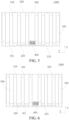
FIG. 2 is a schematic top view of the structure of the power battery heat exchanger in the related art; -
FIG. 3 is a schematic diagram of a structure of a power battery system according to an exemplary embodiment of the present disclosure, which shows mounting of a power battery heat exchanger and a power battery. -
FIG. 4 is an exploded view of the power battery system inFIG. 3 ; -
FIG. 5 is a schematic diagram of flow of a refrigerant in a power battery heat exchanger according to an exemplary embodiment of the present disclosure; -
FIG. 6 is a schematic diagram of flow of a refrigerant in a power battery heat exchanger according to another exemplary embodiment of the present disclosure; -
FIG. 7 is a schematic diagram of a partial structure of a connector of a power battery heat exchanger according to an exemplary embodiment of the present disclosure; -
FIG. 8 is a schematic diagram of a structure of a first collecting tube assembly in a power battery heat exchanger according to an exemplary embodiment of the present disclosure; -
FIG. 9 is a schematic diagram of a partial structure of a harmonica tube of a power battery heat exchanger according to an exemplary embodiment of the present disclosure; and -
FIG. 10 is a block diagram of a structure of an electric vehicle according to an exemplary embodiment of the present disclosure. - The following describes specific implementations of the present disclosure in detail with reference to the accompanying drawings. It should be understood that the specific implementations described herein are merely used to describe and explain the present disclosure, but are not intended to limit the present disclosure.
- In the present disclosure, unless otherwise stated, used orientation words such as "up, down, left, and right", generally refer to up, down, left, and right of the accompanying drawing; "inner and outer" refer to "inner and outer" with respect to an outline of a corresponding component; "X" refers to a first direction; and "Y" refers to a second direction. In addition, terms "first", "second", "third", "fourth", and the like used in the present disclosure are to distinguish one element from another element, and do not have order and importance. In addition, when the following descriptions are made with reference to the accompanying drawings, unless otherwise explained, the same reference numerals in different accompanying drawings represent the same or similar elements. The foregoing definitions are merely used to explain and illustrate the present disclosure, and are not to be construed as a limitation on the present disclosure.
- In the related art, a heat exchanger for direct cooling of a power battery is shown in
FIG. 1 and FIG. 2 . The heat exchanger is mainly formed by welding aharmonica tube 10, acollecting tube assembly 20, a tailend collecting tube 30, aconnector 40, and avapor chamber 50. Theconnector 40 is connected to an air conditioning system of a whole vehicle. Theconnector 40, thecollecting tube assembly 20, the tailend collecting tube 30, and theharmonica tube 10 are welded together to form the heat exchanger with a flow channel inside. Thevapor chamber 50 is welded and fixed to theharmonica tube 10. Currently, the heat exchanger is connected to the whole vehicle through a two-hole connector, and the harmonica tube is used as a component that exchanges heat with a battery in the entire heat exchanger. To maximize a capability of the heat exchanger, the harmonica tube covers the power battery. Therefore, a connection between the connector and the harmonica tube needs to be transitioned through a collecting tube assembly. The collectingtube assembly 20 of the heat exchanger is formed by nine round tubes and two three-channel tubes. In addition, the collecting tube assembly cannot be in direct contact with the battery, and cannot heat or cool a battery system, causing heat or cold loss and reducing heat exchange efficiency of the heat exchanger. - As shown in
FIG. 3 to FIG. 9 , to achieve the foregoing objectives, according to a first aspect of the present disclosure, a powerbattery heat exchanger 1000 is provided and includes aconnector 400, avapor chamber 500, a firstcollecting tube assembly 200 and a secondcollecting tube assembly 300 arranged spaced away in a first direction X, and a number ofharmonica tubes 100 arranged between the firstcollecting tube assembly 200 and the secondcollecting tube assembly 300 and arranged at intervals in a second direction Y. The number ofharmonica tubes 100 are connected to thevapor chamber 500. The first direction X is perpendicular to the second direction Y. Theharmonica tube 100 includes afirst end 101 and asecond end 102 that are opposite to each other. The firstcollecting tube assembly 200 includes afirst collecting tube 210 and asecond collecting tube 220. Theconnector 400 includes aninlet 401 and anoutlet 402. Theinlet 401 of theconnector 400 is respectively in communication withfirst ends 101 of someharmonica tubes 100 through thefirst collecting tube 210. Theoutlet 402 of theconnector 400 is respectively in communication withfirst ends 101 ofother harmonica tubes 100 through thesecond collecting tube 220. Second ends 102 of the number ofharmonica tubes 100 are in communication through the secondcollecting tube assembly 300. - Through the foregoing technical solutions, that is, the power
battery heat exchanger 1000 of the present disclosure, thefirst collecting tube 210 and thesecond collecting tube 220 are arranged as the firstcollecting tube assembly 200, and thefirst collecting tube 210 and thesecond collecting tube 220 are respectively in communication with theinlet 401 and theoutlet 402 of theconnector 400. In this way, a refrigerant entering through theinlet 401 directly enters someharmonica tubes 100 after passing through thefirst collecting tube 210, is combined by the secondcollecting tube assembly 300 and flows into remainingharmonica tubes 100, and finally passes through thesecond collecting tube 220 and flows out through theoutlet 402 of theconnector 400 to form a circuit. The number ofharmonica tubes 100 exchange heat for thepower battery 600 through thevapor chamber 500, to heat or cool thepower battery 600. In the powerbattery heat exchanger 1000 of the present disclosure, the firstcollecting tube assembly 200 includes only thefirst collecting tube 210 and thesecond collecting tube 220. In this way, a quantity of lines of the firstcollecting tube assembly 200 is reduced as a whole, which has high space utilization, avoids ineffective heat exchange, improves heat exchange efficiency of the powerbattery heat exchanger 1000, and reduces material costs. - It should be noted that the
inlet 401 and theoutlet 402 of theconnector 400 are configured for inflow and outflow of the refrigerant in the entire powerbattery heat exchanger 1000. Theharmonica tube 100 has a number offlow channels 110 inside. Theconnector 400, thefirst collecting tube 210, thesecond collecting tube 220, theharmonica tube 100, and the secondcollecting tube assembly 300 are embedded and welded to each other, and channels in components are in communication with each other to form a channel for flow of the refrigerant in the powerbattery heat exchanger 1000. To increase a heat exchange area of the entire powerbattery heat exchanger 1000, thevapor chamber 500 and theharmonica tube 100 are welded together. - It should be noted that the first direction X is perpendicular to the second direction Y. To be specific, an extending direction of the number of
harmonica tubes 100 is perpendicular to an extending direction of thefirst collecting tube 210, thesecond collecting tube 220, and the secondcollecting tube assembly 300, which facilitates flow uniformity of the refrigerant from the collecting tubes into theharmonica tubes 100. - In some embodiments, the first direction X and the second direction Y may alternatively be at an angle, but are not vertically arranged, which may also meet the foregoing communication requirement. For example, the
harmonica tube 100 may extend in the first direction X, thefirst collecting tube 210 and thesecond collecting tube 220 extend in the second direction Y, and an angle between the first direction X and the second direction Y is 15°, 30°, 45°, 60°, 75°, 105°, 120°, 135°, 150°, 165°, or the like. - As shown in
FIG. 3 , thepower battery 600 adopts a long-battery transverse arrangement solution. Two ends of thepower battery 600 are respectively a batterypositive pole 610 and a batterynegative pole 620. The batterypositive electrode 610 of thepower battery 600 is arranged toward the batterynegative electrode 620 in a direction consistent with the second direction Y of the powerbattery heat exchanger 1000. When thepower battery 600 is at a high temperature, temperatures of the positive and negative poles at the two ends of thepower battery 600 are higher than a temperature in the middle. Therefore, when thepower battery 600 cools down, the cooling of the two ends of thepower battery 600 needs to be considered first. - In some embodiments, in the second direction Y, at least two
outermost harmonica tubes 100 are in communication with thefirst collecting tube 210. As shown inFIG. 5 and FIG. 6 , first ends 101 of at least leftmost andrightmost harmonica tubes 100 are in communication with thefirst collecting tube 210, to serve as a channel for the refrigerant to first enter, which has the best cooling effect. First ends 101 ofother harmonica tubes 100 located at a middle position are in communication with thesecond collecting tube 220, and serve as a channel for the refrigerant to finally flow out. The cooling effect is slightly poorer than that of the twooutermost harmonica tubes 100, to meet an actual use requirement of thepower battery 600 and reduce a temperature difference of thepower battery 600. It should be noted that the second ends 102 of the number ofharmonica tubes 100 are in communication through the secondcollecting tube assembly 300. In this way, the number ofharmonica tubes 100 are in communication to form flow of the refrigerant. - According to the foregoing temperature feature of the
power battery 600 that the temperature at the two ends is relatively high and the temperature in the middle is relatively low, a flow direction of the refrigerant in theharmonica tubes 100 of the powerbattery heat exchanger 1000 is redesigned. The foregoing powerbattery heat exchanger 1000 is connected to the air conditioning system. In other words, the refrigerant in the air conditioning system enters through theinlet 401 of theconnector 400, flows to thefirst collecting tube 210, then is divided from thefirst collecting tube 210 to the left and rightoutermost harmonica tubes 100 orharmonica tubes 100 close to the outside, flows back through the secondcollecting tube assembly 300 andother harmonica tubes 100 to thesecond collecting tube 220, and then flows out through theoutlet 402 of theconnector 400 to the air conditioning system. The powerbattery heat exchanger 1000 is hardly connected and connected in parallel in the air conditioning system of the whole vehicle through theconnector 400. When the power battery system needs to reduce a temperature, an air conditioning controller controls the refrigerant to flow to the powerbattery heat exchanger 1000, which has an effect of reducing the temperature of thepower battery 600. - Similarly, when the temperature of the
power battery 600 is relatively low, and when heating is required, the refrigerant enters through theoutlet 402 of theconnector 400, flows through thesecond collecting tube 220 and a number ofharmonica tubes 100 at the middle position, flows back through the secondcollecting tube assembly 300 andother harmonica tubes 100 on the outside to thefirst collecting tube 210, and then flows out through theinlet 401 of theconnector 400 to the air conditioning system, so that heating of the power battery may be implemented. - It should be noted that the
first collecting tube 210 and thesecond collecting tube 220 may both be aluminum tubes, or may be made of other metal materials, for example, copper or aluminum alloy materials. - To further improve uniformity of cooling and heating of the power
battery heat exchanger 1000, as shown inFIG. 5 and FIG. 6 , in some embodiments of the present disclosure, a quantity ofharmonica tubes 100 is an even number, and a quantity ofharmonica tubes 100 connected to thefirst collecting tube 210 is equal to a quantity ofharmonica tubes 100 connected to thesecond collecting tube 220. It is equivalent to that, a flow rate of the refrigerant flowing into theharmonica tube 100 and a flow rate of the refrigerant flowing out of theharmonica tube 100 can be maintained to be substantially equal. In other words, in a case that the flow directions of the refrigerants indifferent harmonica tubes 100 are set according to the feature of thepower battery 600 to adapt to different temperatures at the two ends of thepower battery 600 and the middle portion of thepower battery 600, the flow rates and pressure drops all over the powerbattery heat exchanger 1000 can be maintained to be uniform to some extent. - As shown in
FIG. 5 , in some embodiments, the quantity ofharmonica tubes 100 is eight. In the second direction, fourinnermost harmonica tubes 100 are respectively in communication with thesecond collecting tube 220, and other fourharmonica tubes 100 are respectively in communication with thefirst collecting tube 210. The first ends 101 of twoleftmost harmonica tubes 100 and tworightmost harmonica tubes 100 are respectively in communication with thefirst collecting tube 210, the first ends 101 of the fourharmonica tubes 100 at the middle position are respectively in communication with thesecond collecting tube 220, and the second ends 102 of the eightharmonica tubes 100 are respectively in communication through the secondcollecting tube assembly 300. In a cooling process, the refrigerant of the air conditioning system enters through theinlet 401 of theconnector 400, and flows through thefirst collecting tube 210 to the fourharmonica tubes 100 on the left side and the right side respectively. The refrigerant merges in the secondcollecting tube assembly 300 at second ends 102 of the fourharmonica tubes 100, then flows into thesecond collecting tube 220 through the fourharmonica tubes 100 that are in communication with the secondcollecting tube assembly 300 and that are located at the middle position, and flows back into the air conditioning system through theoutlet 402 of theconnector 400. In a flow process, the refrigerant first enters the twoleftmost harmonica tubes 100 and the tworightmost harmonica tubes 100, and cools the two ends of thepower battery 600 with a relatively high temperature, so that thepower battery 600 can reach a suitable temperature range most quickly. Then, the fourharmonica tubes 100 at the middle position cool the middle position of the battery, which can also meet a temperature requirement of thepower battery 600. In a heating process, the flow direction is exactly opposite. To be specific, the refrigerant enters through theoutlet 402 of theconnector 400 and flows out through theinlet 401 of theconnector 400, so that the heating of the battery can be implemented. Compared with the related art, in the firstcollecting tube assembly 200 of the present disclosure, a quantity of diverting tubes is simplified, and heat loss is avoided. Therefore, through the foregoing eightharmonica tubes 100 in combination with thevapor chamber 500, a heat dissipation requirement can be met. - As shown in
FIG. 6 , in some other embodiments, the quantity ofharmonica tubes 100 is eight. In the second direction, twooutermost harmonica tubes 100 and twoinnermost harmonica tubes 100 are respectively in communication with thefirst collecting tube 210, and other fourharmonica tubes 100 are respectively in communication with thesecond collecting tube 220. In the second direction Y, first ends 101 of the leftmost andrightmost harmonica tubes 100 and two midmost harmonica tubes are respectively in communication with thefirst collecting tube 210, while first ends 101 of remaining fourharmonica tubes 100 are respectively in communication with thesecond collecting tube 220, and second ends 102 of the eightharmonica tubes 100 are respectively in communication with the secondcollecting tube assembly 300. In a cooling process, the refrigerant of the air conditioning system enters through theinlet 401 of theconnector 400 and flows through thefirst collecting tube 210 to four harmonica tubes 100: the rightmost one, the leftmost one, and the midmost two. The refrigerant merges in the secondcollecting tube assembly 300 at second ends 102 of the fourharmonica tubes 100, then flows into thesecond collecting tube 220 through twoharmonica tubes 100 that are in communication with the secondcollecting tube assembly 300 and that are located between theleftmost harmonica tube 100 and themidmost harmonica tubes 100 and twoharmonica tubes 100 that are located between therightmost harmonica tube 100 and themidmost harmonica tubes 100, and flows back into the air conditioning system through theoutlet 402 of theconnector 400. In a flow process, the refrigerant first enters theleftmost harmonica tube 100, therightmost harmonica tube 100, and themidmost harmonica tubes 100, and cools the two ends of thepower battery 600 with a relatively high temperature and the midmost position that is less prone to heat dissipation. In this way, the power battery can reach a suitable temperature range most quickly. Then, the other fourharmonica tubes 100 cool a position between the two ends and the middle portion of the battery, further meeting the temperature requirement of thepower battery 600. In a heating process, the flow direction is exactly the opposite. To be specific, the refrigerant enters through theoutlet 402 of theconnector 400 and flows out through theinlet 401 of theconnector 400, so that the heating of the battery can be implemented. Details are not described herein again. - The second
collecting tube assembly 300 may be constructed by using any appropriate structure, and may be formed by using a tube extending in the second direction Y and having two ends sealed. The tube includes, but is not limited to, an aluminum tube. As shown inFIG. 6 , in some embodiments of the present disclosure, the secondcollecting tube assembly 300 includes athird collecting tube 310 and afourth collecting tube 320. Thethird collecting tube 310 is in communication withsecond ends 102 of four adjacently arrangedharmonica tubes 100. Thefourth collecting tube 320 is in communication withsecond ends 102 of other four adjacently arrangedharmonica tubes 100. That is, thethird collecting tube 310 is in communication with the second ends 102 of the left fourharmonica tubes 100. During cooling, among the fourharmonica tubes 100, the refrigerant flows from the twoharmonica tubes 100 on the two sides into thethird collecting tube 310, and the refrigerant in thethird collecting tube 310 flows into the twomiddle harmonica tubes 100. In addition, thefourth collecting tube 320 is in communication with the second ends 102 of the right fourharmonica tubes 100. During cooling, among the fourharmonica tubes 100, the refrigerant flows from the twoharmonica tubes 100 on the two sides into thefourth collecting tube 320, and the refrigerant in thefourth collecting tube 320 flows into the twomiddle harmonica tubes 100. During heating, the flow direction is exactly opposite. It may also be understood that the eightharmonica tubes 100 are divided into a left group and a right group, to avoid affecting flow distribution of the refrigerant in eachharmonica tube 100 as a result of merging when the refrigerant flows into the secondcollecting tube assembly 300, and further improve flow stability during cooling or heating. - In some embodiments, the second
collecting tube assembly 300 may alternatively be a straight tube extending in the second direction. Two ends of the straight tube are sealed, and the second ends 102 of the number ofharmonica tubes 100 are respectively connected to the straight tube at intervals. In this way, it is also possible that the refrigerant flows into someharmonica tubes 100, and flows out fromother harmonica tubes 100. It should be noted that to achieve the foregoing effect of improving the stability of the internal flow rate, a block seal member may be arranged at a middle position of the straight tube, and the straight tube is divided into two sections. The left fourharmonica tubes 100 are in communication with one of the sections, and the right fourharmonica tubes 100 are in communication with other sections, which can also achieve the objective of stabilizing the flow rate. - To improve reliability of connection of the
first collecting tube 210 and thesecond collecting tube 220 to theharmonica tube 100, as shown inFIG. 8 andFIG. 9 , in some embodiments of the present disclosure, thefirst collecting tube 210 is provided with a number of first strip holes 211 extending in a length direction of thefirst collecting tube 210, and theharmonica tube 100 is fixedly connected to thefirst strip hole 211, to cause a number offlow channels 110 of theharmonica tube 100 to be in communication with thefirst collecting tube 210. Thefirst collecting tube 210 is provided with a number of first strip holes 211 corresponding to a width of theharmonica tube 100. Theharmonica tube 100 is embedded in thefirst strip hole 211 and is connected to thefirst strip hole 211 by welding. - In some embodiments, the
second collecting tube 220 is provided with a number of second strip holes 221 extending in a length direction of thesecond collecting tube 220, and theharmonica tube 100 is fixedly connected to thesecond strip hole 221, to cause the number offlow channels 110 of theharmonica tube 100 to be in communication with thesecond collecting tube 220. Thesecond collecting tube 220 is provided with a number of second strip holes 221 corresponding to the width of theharmonica tube 100. Theharmonica tube 100 is embedded in thesecond strip hole 221 and is connected to thesecond strip hole 221 by welding. - It should be noted that as shown in
FIG. 9 , an end of theharmonica tube 100 is curved downward relative to a portion connecting theharmonica tube 100 to thevapor chamber 500, and is connected to the firstcollecting tube assembly 200, for wrapping thepower battery 600 when connected to thepower battery 600. The other end may be a straight section, that is, the straight section and the portion connected to thevapor chamber 500 may be in a same plane, that is, the other end is not curved and is directly connected to the secondcollecting tube assembly 300. - The
connector 400 may be configured in any appropriate manner. As shown inFIG. 7 and FIG. 8 , in some embodiments of the present disclosure, theconnector 400 may include theinlet 401, theoutlet 402, a liquid inlet 403 in communication with theinlet 401, and aliquid outlet 404 in communication with theoutlet 402. The liquid inlet 403 is in communication with thefirst collecting tube 210 through afirst connection tube 230, and theliquid outlet 404 is in communication with thesecond collecting tube 220 through asecond connection tube 240. Theconnector 400 is connected to the lines of the air conditioning system through theinlet 401 and theoutlet 402 of theconnector 400. For example, the connector may be connected to a refrigerating and heating line of a vehicle cab, definitely, or may be connected to other corresponding lines that can achieve refrigerating and heating, provided that heat exchange of thepower battery 600 is implemented. - In the related art, as shown in
FIG. 1 and FIG. 2 , the heat exchanger is mainly formed by welding theharmonica tube 10, the collecting tube assembly, the tail end collecting tube, theconnector 40, and thevapor chamber 50. Theconnector 40 is connected to the air conditioning system of the whole vehicle. Theconnector 40, the collecting tube assembly, and theharmonica tube 10 are welded together to form a heat exchanger with a flow channel inside. Thevapor chamber 50 is welded and fixed to theharmonica tube 10. The collecting tube assembly includes a total of 9 tubes: two connection tubes, two three-channel valves, four diverting tubes, a collecting tube 1, and two collecting tubes 2. Theconnector 40 is respectively connected to the two three-channel valves through the two connection tubes. The three-channel valve is further connected to the two collecting tubes 2 through a left diverting tube and a right diverting tube with a diverting function. The three-channel valve is connected to the collecting tube 1 through the two diverting tubes with left and right shunting functions. As shown inFIG. 2 , the inlet and the outlet are integrated into theconnector 40. For example, the collecting tube assembly may be formed by 9 round tubes. The collecting tube assembly serves as a transition assembly between theconnector 40 and theharmonica tubes 10, and plays a role of distributing a flow rate of theconnector 40 to theharmonica tubes 10. As shown inFIG. 2 , the refrigerant flows in from the inlet of theconnector 40 and is divided into a left flow channel and a right flow channel, and each flow channel is further divided into two flow channels. Finally, in the collecting tube 1, the refrigerant flows into four flow channels to theharmonica tube 10. The flow channels flow to the tail end collecting tube, and then reversely flow from the other fourharmonica tubes 10 back to the collecting tube 2 of the collecting tube assembly. The four flow channels merge into two flow channels, then merge into a flow channel, and flow out of the outlet of the connector. - Compared with the solutions in the foregoing related art, according to the power
battery heat exchanger 1000 provided in the present disclosure, the quantity of lines of the collecting tube assembly in the heat exchanger is reduced from the original 9 to 4. In this way, the materials are reduced, and the production costs are reduced. In addition, since the original 9 lines on the collecting tube assembly are arranged outside thepower battery 600, the effect of reducing the temperature of the battery cannot be achieved. Currently, the quantity of lines of the collecting tube assembly is reduced to 4, which can reduce ineffective heat exchange and improve the heat exchange efficiency of the heat exchanger. - According to a second aspect of the present disclosure, a
power battery system 2000 is further provided and includes apower battery 600. Thepower battery system 2000 further includes the foregoing powerbattery heat exchanger 1000. The powerbattery heat exchanger 1000 is arranged on a surface of thepower battery 600, and is configured to heat and/or cool thepower battery 600. A heater of thepower battery 600, that is, theharmonica tube 100 and thevapor chamber 500 may be arranged on an upper surface of thepower battery 600, or may be arranged on a lower surface of thepower battery 600, provided that cooling or heating of thepower battery 600 can be implemented. In addition, that the powerbattery heat exchanger 1000 is arranged on a surface of thepower battery 600 may be understood as being directly or indirectly arranged on the surface of thepower battery 600. For example, the powerbattery heat exchanger 1000 may be attached to the surface of thepower battery 600 or a thermally conductive adhesive may be arranged between the powerbattery heat exchanger 1000 and thepower battery 600. The powerbattery heat exchanger 1000 is bonded to the surface of thepower battery 600 through the thermally conductive adhesive. - A direction of the two ends of the power battery 600 (that is, a direction of a battery
positive pole 610 of thepower battery 600 facing a battery negative pole 620) corresponds to the second direction of the powerbattery heat exchanger 1000. To be specific, in the second direction, at least twooutermost harmonica tubes 100 correspond to the two ends of thepower battery 600, to improve a cooling capability at the two ends of thepower battery 600 when cooling is required, and improve a heating capability at the middle position of the battery when heating is required. - As shown in
FIG. 10 , according to a third aspect of the present disclosure, anelectric vehicle 3000 is further provided. Theelectric vehicle 3000 includes the foregoingpower battery system 2000. Therefore, theelectric vehicle 3000 also has advantages of the foregoingpower battery system 2000. Details are not described herein again. - The optional implementations of the present disclosure are described in detail above with reference to the accompanying drawings. However, the present disclosure is not limited to the specific details in the foregoing implementations, a number of simple deformations may be made to the technical solution of the present disclosure within a range of the technical concept of the present disclosure, and these simple deformations fall within the protection scope of the present disclosure.
- In addition, it should be noted that, the specific technical features described in the above specific implementations may be combined in any suitable manner without contradiction. To avoid unnecessary repetition, various possible combinations are not further described in the present disclosure.
- In addition, the various implementations of the present disclosure may be combined arbitrarily as long as it does not deviate from the idea of the present disclosure, and the combination should also be regarded as the contents of the present disclosure.
Claims (12)
- A power battery heat exchanger (1000), comprising:a connector (400), the connector (400) comprising an inlet (401) and an outlet (402);a first collecting tube assembly (200) and a second collecting tube assembly (300) arranged spaced away in a first direction, the first collecting tube assembly (200) comprising a first collecting tube (210) and a second collecting tube (220); anda plurality of harmonica tubes (100), arranged between the first collecting tube assembly (200) and the second collecting tube assembly (300) and arranged at intervals in a second direction; the harmonica tube (100) comprising a first end (101) and a second end (102) that are opposite to each other; the inlet (401) of the connector (400) being respectively in communication with first ends (101) of some harmonica tubes (100) through the first collecting tube (210), and the outlet (402) of the connector (400) being respectively in communication with first ends (101) of other harmonica tubes (100) through the second collecting tube (220); and second ends (102) of the plurality of harmonica tubes (100) being in communication through the second collecting tube assembly (300).
- The power battery heat exchanger (1000) according to claim 1, wherein the first direction is perpendicular to the second direction.
- The power battery heat exchanger (1000) according to claim 1 or 2, wherein in the second direction, at least two outermost harmonica tubes (100) are in communication with the first collecting tube (210).
- The power battery heat exchanger (1000) according to any one of claims 1 to 3, wherein a quantity of harmonica tubes (100) is an even number, and a quantity of harmonica tubes (100) connected to the first collecting tube (210) is equal to a quantity of harmonica tubes (100) connected to the second collecting tube (220).
- The power battery heat exchanger (1000) according to any one of claims 1 to 4, wherein the quantity of harmonica tubes (100) is eight, in the second direction, four innermost harmonica tubes (100) are respectively in communication with the second collecting tube (220), and other four harmonica tubes (100) are respectively in communication with the first collecting tube (210).
- The power battery heat exchanger (1000) according to any one of claims 1 to 4, wherein the quantity of harmonica tubes (100) is eight, in the second direction, two outermost harmonica tubes (100) and two innermost harmonica tubes (100) are respectively in communication with the first collecting tube (210), and other four harmonica tubes (100) are respectively in communication with the second collecting tube (220).
- The power battery heat exchanger (1000) according to claim 6, wherein the second collecting tube assembly (300) comprises a third collecting tube (310) and a fourth collecting tube (320);
the third collecting tube (310) is in communication with second ends (102) of four adjacently arranged harmonica tubes (100); and the fourth collecting tube (320) is in communication with second ends (102) of other four adjacently arranged harmonica tubes (100). - The power battery heat exchanger (1000) according to any one of claims 1 to 7, the power battery heat exchanger (1000) further comprising a vapor chamber (500) arranged on a side of the plurality of harmonica tubes (100), the plurality of harmonica tubes (100) being fixedly connected to the vapor chamber (500).
- The power battery heat exchanger (1000) according to any one of claims 1 to 8, wherein the first collecting tube (210) is provided with a plurality of first strip holes (211) extending in a length direction of the first collecting tube (210), and the harmonica tube (100) is fixedly connected to the first strip hole (211), to cause a plurality of flow channels (110) of the harmonica tube (100) to be in communication with the first collecting tube (210); and/or
the second collecting tube (220) is provided with a plurality of second strip holes (221) extending in a length direction of the second collecting tube (220), and the harmonica tube (100) is fixedly connected to the second strip hole (221), to cause the plurality of flow channels (110) of the harmonica tube (100) to be in communication with the second collecting tube (220). - The power battery heat exchanger (1000) according to any one of claims 1 to 9, wherein the connector (400) comprises a liquid inlet (403) in communication with the inlet (401) and a liquid outlet (404) in communication with the outlet (402), the liquid inlet (403) is in communication with the first collecting tube (210) through a first connection tube (230), and the liquid outlet (404) is in communication with the second collecting tube (220) through a second connection tube (240).
- A power battery system (2000), comprising a power battery (600), further comprising the power battery heat exchanger (1000) according to any one of claims 1 to 10, the power battery heat exchanger (1000) being arranged on a surface of the power battery (600) and being configured to heat and/or cool the power battery (600).
- An electric vehicle (3000), comprising the power battery system (2000) according to claim 11.
Applications Claiming Priority (2)
| Application Number | Priority Date | Filing Date | Title |
|---|---|---|---|
| CN202210772688.XA CN117374481B (en) | 2022-06-30 | 2022-06-30 | Power battery heat exchanger, power battery system and electric vehicle |
| PCT/CN2023/103477 WO2024002198A1 (en) | 2022-06-30 | 2023-06-28 | Power battery heat exchanger, power battery system and electric vehicle |
Publications (2)
| Publication Number | Publication Date |
|---|---|
| EP4550523A1 true EP4550523A1 (en) | 2025-05-07 |
| EP4550523A4 EP4550523A4 (en) | 2026-04-29 |
Family
ID=89383145
Family Applications (1)
| Application Number | Title | Priority Date | Filing Date |
|---|---|---|---|
| EP23830369.7A Pending EP4550523A4 (en) | 2022-06-30 | 2023-06-28 | Electric battery heat exchanger, electric battery system and electric vehicle |
Country Status (6)
| Country | Link |
|---|---|
| US (1) | US20250132415A1 (en) |
| EP (1) | EP4550523A4 (en) |
| JP (1) | JP2025518931A (en) |
| KR (1) | KR20250018553A (en) |
| CN (1) | CN117374481B (en) |
| WO (1) | WO2024002198A1 (en) |
Families Citing this family (1)
| Publication number | Priority date | Publication date | Assignee | Title |
|---|---|---|---|---|
| DE102022134765A1 (en) * | 2022-12-23 | 2024-07-04 | Polytec Plastics Germany Gmbh & Co. Kg | Countercurrent tempering device, battery housing for use with a tempering device |
Family Cites Families (25)
| Publication number | Priority date | Publication date | Assignee | Title |
|---|---|---|---|---|
| JP2011181224A (en) * | 2010-02-26 | 2011-09-15 | Sanyo Electric Co Ltd | Battery cooling/heating structure and battery module |
| JP6167023B2 (en) * | 2013-11-22 | 2017-07-19 | 昭和電工株式会社 | Battery cooling structure |
| DE102014106954B4 (en) * | 2014-05-16 | 2024-12-24 | Valeo Klimasysteme Gmbh | Device for heating and cooling a battery pack and vehicle drive battery assembly |
| CN204809357U (en) * | 2015-07-27 | 2015-11-25 | 宁德时代新能源科技有限公司 | Hot management component of group battery |
| CN109728376B (en) * | 2017-10-30 | 2021-12-14 | 杭州三花研究院有限公司 | Board assembly and battery pack |
| JP7024391B2 (en) * | 2017-12-25 | 2022-02-24 | 三菱自動車工業株式会社 | Vehicle battery temperature control device structure |
| CN209119270U (en) * | 2018-09-19 | 2019-07-16 | 湖北雷迪特冷却系统股份有限公司 | A kind of mouth organ tubular type water-cooled plate connection structure |
| CN208939114U (en) * | 2018-10-29 | 2019-06-04 | 东风汽车集团有限公司 | A water-cooling plate for electric vehicle power battery and a battery pack containing the water-cooling plate |
| CN209675451U (en) * | 2019-03-27 | 2019-11-22 | 湖北雷迪特冷却系统股份有限公司 | A dry-wet separation battery liquid cold plate assembly |
| CN209357873U (en) * | 2019-03-29 | 2019-09-06 | 成都富临精工电子电器科技有限公司 | A kind of plate structure of cooling |
| CN110120566A (en) * | 2019-05-07 | 2019-08-13 | 奇瑞新能源汽车技术有限公司 | A kind of power battery cooling system for electronic vehicle and electric car |
| CN210489780U (en) * | 2019-07-29 | 2020-05-08 | 法雷奥汽车空调湖北有限公司动力总成热系统分公司 | Cooling plate with flow guide pipe |
| CN210576328U (en) * | 2019-09-24 | 2020-05-19 | 法雷奥汽车空调湖北有限公司动力总成热系统分公司 | Cooling plate cooled by cooling liquid |
| CN111430841B (en) * | 2020-04-04 | 2021-09-03 | 东风汽车集团有限公司 | Power battery cooling and heating system |
| CN113707969A (en) * | 2020-05-08 | 2021-11-26 | 恒大新能源技术(深圳)有限公司 | Liquid cooling plate, battery pack and flow control method |
| CN213026246U (en) * | 2020-07-28 | 2021-04-20 | 重庆宏美制冷设备有限公司 | Heat exchange liquid cooling plate structure |
| CN214666270U (en) * | 2020-08-26 | 2021-11-09 | 广东美的暖通设备有限公司 | Heat Exchangers, Electric Control Boxes and Air Conditioning Systems |
| CN212874592U (en) * | 2020-08-31 | 2021-04-02 | 湖北亿纬动力有限公司 | Heat exchange assembly and heat exchange device |
| CN212810398U (en) * | 2020-09-17 | 2021-03-26 | 重庆金康动力新能源有限公司 | Cooling device, battery system and vehicle |
| CN214280121U (en) * | 2021-02-04 | 2021-09-24 | 无锡明恒混合动力技术有限公司 | A harmonica tube heat exchange side plate for square battery module |
| CN113629313A (en) * | 2021-06-25 | 2021-11-09 | 东风汽车集团股份有限公司 | Liquid cooling device, power battery and vehicle |
| CN216671797U (en) * | 2021-12-30 | 2022-06-03 | 北京胜能能源科技有限公司 | Power battery module of integrated liquid cooling board subassembly |
| CN114335805A (en) * | 2021-12-30 | 2022-04-12 | 北京胜能能源科技有限公司 | A power battery module with integrated liquid cold plate assembly |
| CN217788542U (en) * | 2022-06-30 | 2022-11-11 | 比亚迪股份有限公司 | Heat exchanger of power battery, battery pack and vehicle |
| CN218241987U (en) * | 2022-09-01 | 2023-01-06 | 比亚迪股份有限公司 | Battery pack and vehicle |
-
2022
- 2022-06-30 CN CN202210772688.XA patent/CN117374481B/en active Active
-
2023
- 2023-06-28 EP EP23830369.7A patent/EP4550523A4/en active Pending
- 2023-06-28 KR KR1020257000068A patent/KR20250018553A/en active Pending
- 2023-06-28 JP JP2024572486A patent/JP2025518931A/en active Pending
- 2023-06-28 WO PCT/CN2023/103477 patent/WO2024002198A1/en not_active Ceased
-
2024
- 2024-12-20 US US18/990,314 patent/US20250132415A1/en active Pending
Also Published As
| Publication number | Publication date |
|---|---|
| CN117374481A (en) | 2024-01-09 |
| CN117374481B (en) | 2024-12-10 |
| KR20250018553A (en) | 2025-02-06 |
| US20250132415A1 (en) | 2025-04-24 |
| WO2024002198A1 (en) | 2024-01-04 |
| JP2025518931A (en) | 2025-06-19 |
| EP4550523A4 (en) | 2026-04-29 |
Similar Documents
| Publication | Publication Date | Title |
|---|---|---|
| CN111490311B (en) | Integrated heat exchange plate and vehicle battery thermal management system | |
| CN103066342B (en) | Battery cooling plate and cooling system | |
| US9920686B2 (en) | Water-cooled charge air cooler with integrated multi-stage cooling | |
| KR20190111773A (en) | Intercooler consisting of a liquid-cooled pre-cooler and an air-cooled main cooler | |
| EP4692682A1 (en) | All-in-one plate heat exchanger, temperature control apparatus comprising same, energy storage device, and vehicle | |
| US12442599B2 (en) | Heat exchanger with optimum baffle | |
| US11603790B2 (en) | Heat exchanger | |
| EP3872435B1 (en) | A heat exchanger | |
| CN117858438A (en) | Heat Exchanger | |
| KR20230042319A (en) | thermal management components | |
| CN211230611U (en) | Chip, chip assembly, core and multistage intercooler | |
| US20250132415A1 (en) | Power battery heat exchanger, power battery system and electric vehicle | |
| CN218270317U (en) | Plate heat exchanger and vehicle | |
| CN111121501B (en) | a heat exchange device | |
| CN114894010B (en) | Heat Exchanger | |
| CN211782979U (en) | Fin and heat exchanger | |
| CN221961078U (en) | Cold plate and cooling system | |
| JP7683025B2 (en) | Cooler including two substantially parallel flow chambers and three substantially parallel plates | |
| CN222012414U (en) | Microchannel heat exchanger and refrigerator | |
| EP4549867A1 (en) | Harmonica-shaped tube, harmonica-shaped tube type heat exchanger and vehicle | |
| US20240102745A1 (en) | Heat exchanger | |
| CN217994055U (en) | Runner integration assembly and vehicle having same | |
| US11561052B2 (en) | Heat exchanger and method of operating a heat exchanger | |
| JP2025514356A (en) | HEAT RADIATOR ASSEMBLY, BATTERY PACK, AND VEHICLE | |
| JP2018508734A (en) | Laminated plate heat exchanger |
Legal Events
| Date | Code | Title | Description |
|---|---|---|---|
| STAA | Information on the status of an ep patent application or granted ep patent |
Free format text: STATUS: THE INTERNATIONAL PUBLICATION HAS BEEN MADE |
|
| PUAI | Public reference made under article 153(3) epc to a published international application that has entered the european phase |
Free format text: ORIGINAL CODE: 0009012 |
|
| STAA | Information on the status of an ep patent application or granted ep patent |
Free format text: STATUS: REQUEST FOR EXAMINATION WAS MADE |
|
| 17P | Request for examination filed |
Effective date: 20250102 |
|
| AK | Designated contracting states |
Kind code of ref document: A1 Designated state(s): AL AT BE BG CH CY CZ DE DK EE ES FI FR GB GR HR HU IE IS IT LI LT LU LV MC ME MK MT NL NO PL PT RO RS SE SI SK SM TR |
|
| DAV | Request for validation of the european patent (deleted) | ||
| DAX | Request for extension of the european patent (deleted) | ||
| A4 | Supplementary search report drawn up and despatched |
Effective date: 20260326 |
|
| RIC1 | Information provided on ipc code assigned before grant |
Ipc: H01M 10/613 20140101AFI20260320BHEP Ipc: H01M 10/6556 20140101ALI20260320BHEP Ipc: H01M 10/6568 20140101ALI20260320BHEP Ipc: B60L 58/26 20190101ALI20260320BHEP Ipc: H01M 10/625 20140101ALI20260320BHEP Ipc: H01M 10/6567 20140101ALI20260320BHEP |