EP4550367A1 - Magnet, elektronische vorrichtung und ladevorrichtung - Google Patents
Magnet, elektronische vorrichtung und ladevorrichtung Download PDFInfo
- Publication number
- EP4550367A1 EP4550367A1 EP24841094.6A EP24841094A EP4550367A1 EP 4550367 A1 EP4550367 A1 EP 4550367A1 EP 24841094 A EP24841094 A EP 24841094A EP 4550367 A1 EP4550367 A1 EP 4550367A1
- Authority
- EP
- European Patent Office
- Prior art keywords
- magnet
- sub
- ring
- magnetic
- face
- Prior art date
- Legal status (The legal status is an assumption and is not a legal conclusion. Google has not performed a legal analysis and makes no representation as to the accuracy of the status listed.)
- Pending
Links
Images


Classifications
-
- H—ELECTRICITY
- H02—GENERATION; CONVERSION OR DISTRIBUTION OF ELECTRIC POWER
- H02J—ELECTRIC POWER NETWORKS; CIRCUIT ARRANGEMENTS OR SYSTEMS FOR SUPPLYING OR DISTRIBUTING ELECTRIC POWER; SYSTEMS FOR STORING ELECTRIC ENERGY
- H02J50/00—Circuit arrangements or systems for wireless supply or distribution of electric power
- H02J50/005—Mechanical details of housing or structure aiming to accommodate the power transfer means, e.g. mechanical integration of coils, antennas or transducers into emitting or receiving devices
-
- H—ELECTRICITY
- H02—GENERATION; CONVERSION OR DISTRIBUTION OF ELECTRIC POWER
- H02J—ELECTRIC POWER NETWORKS; CIRCUIT ARRANGEMENTS OR SYSTEMS FOR SUPPLYING OR DISTRIBUTING ELECTRIC POWER; SYSTEMS FOR STORING ELECTRIC ENERGY
- H02J50/00—Circuit arrangements or systems for wireless supply or distribution of electric power
- H02J50/90—Circuit arrangements or systems for wireless supply or distribution of electric power involving detection or optimisation of position, e.g. alignment
-
- H—ELECTRICITY
- H01—ELECTRIC ELEMENTS
- H01F—MAGNETS; INDUCTANCES; TRANSFORMERS; SELECTION OF MATERIALS FOR THEIR MAGNETIC PROPERTIES
- H01F7/00—Magnets
- H01F7/02—Permanent magnets [PM]
- H01F7/0205—Magnetic circuits with PM in general
- H01F7/021—Construction of PM
-
- H—ELECTRICITY
- H01—ELECTRIC ELEMENTS
- H01F—MAGNETS; INDUCTANCES; TRANSFORMERS; SELECTION OF MATERIALS FOR THEIR MAGNETIC PROPERTIES
- H01F7/00—Magnets
- H01F7/02—Permanent magnets [PM]
- H01F7/0205—Magnetic circuits with PM in general
- H01F7/0221—Mounting means for PM, supporting, coating, encapsulating PM
-
- H—ELECTRICITY
- H01—ELECTRIC ELEMENTS
- H01F—MAGNETS; INDUCTANCES; TRANSFORMERS; SELECTION OF MATERIALS FOR THEIR MAGNETIC PROPERTIES
- H01F7/00—Magnets
- H01F7/02—Permanent magnets [PM]
- H01F7/0231—Magnetic circuits with PM for power or force generation
-
- H—ELECTRICITY
- H02—GENERATION; CONVERSION OR DISTRIBUTION OF ELECTRIC POWER
- H02J—ELECTRIC POWER NETWORKS; CIRCUIT ARRANGEMENTS OR SYSTEMS FOR SUPPLYING OR DISTRIBUTING ELECTRIC POWER; SYSTEMS FOR STORING ELECTRIC ENERGY
- H02J50/00—Circuit arrangements or systems for wireless supply or distribution of electric power
- H02J50/10—Circuit arrangements or systems for wireless supply or distribution of electric power using inductive coupling
-
- H—ELECTRICITY
- H02—GENERATION; CONVERSION OR DISTRIBUTION OF ELECTRIC POWER
- H02J—ELECTRIC POWER NETWORKS; CIRCUIT ARRANGEMENTS OR SYSTEMS FOR SUPPLYING OR DISTRIBUTING ELECTRIC POWER; SYSTEMS FOR STORING ELECTRIC ENERGY
- H02J7/00—Circuit arrangements for charging or discharging batteries or for supplying loads from batteries
- H02J7/70—Circuit arrangements for charging or discharging batteries or for supplying loads from batteries characterised by the mechanical construction
Definitions
- This application relates to the field of terminal device hardware, and specifically, to a magnet, an electronic device, and a charging device.
- a magnet is a necessary component for implementing functions such as magnetic charging of the electronic device. How to control a volume of the magnet and reduce space occupied by the magnet on a premise of providing a sufficiently strong magnetic attraction force is a problem worth considering.
- This application provides a magnet.
- a direction of a magnetic line inside the magnet is inclined toward a plane on which the magnet is located.
- Magnetic lines at a side that is of the magnet and that is used to generate an interaction force with another magnet are denser.
- the magnet with a smaller volume can provide a stronger magnetic attraction force, and has smaller impact on magnetic sensitive components at a back and a side of the magnet.
- a magnet includes: a plurality of magnet units.
- the plurality of magnet units are arranged in a ring shape.
- the magnet unit includes a first magnet subunit and a second magnet subunit.
- the first magnet subunit and the second magnet subunit are relatively fastened.
- a first magnetic pole of the first magnet subunit is adjacent to a second magnetic pole of the second magnet subunit.
- the first magnetic pole and the second magnetic pole are opposite. Both the first magnetic pole and the second magnetic pole are disposed close to a same face of the magnet.
- a direction of a magnetic line inside the first magnet subunit is inclined toward a plane on which the magnet is located, and a direction of a magnetic line inside the second magnet subunit is inclined toward the plane on which the magnet is located.
- the direction of the magnetic line inside the first magnet subunit may also be understood as a magnetization direction inside the first magnet subunit
- the direction of the magnetic line inside the second magnet subunit may also be understood as a magnetization direction inside the second magnet subunit.
- direction of the magnetic line is inclined toward the plane on which the magnet is located should be understood as that the direction of the magnetic line is neither perpendicular to the plane on which the magnet is located nor parallel to the plane on which the magnet is located.
- Directions of magnetic lines inside the first magnet subunit and the second magnet subunit are obliquely disposed, and magnetic poles that are of the first magnet subunit and the second magnet subunit and that are close to each other are oppositely disposed. In this way, more magnetic lines may be aggregated at a side of a working face of the magnet.
- the magnet provided in this technical solution can generate a stronger interaction force with the another magnet. From another perspective, when generated interaction forces are equal, the magnet provided in this technical solution has a smaller volume, and occupies smaller space when the magnet is accommodated in an electronic device.
- the plurality of magnet units are included in the magnet in the ring shape.
- the plurality of magnet units may have different assembly manners. This technical solution helps improve scenario applicability of the magnet provided in this application.
- an included angle between the direction of the magnetic line inside the first magnet subunit and the plane on which the magnet is located is ⁇
- an included angle between the direction of the magnetic line inside the second magnet subunit and the plane on which the magnet is located is ⁇ . 30 ⁇ 90°, and 30 ⁇ 90°.
- the first magnet subunit and the second magnet subunit within a tilt angle range provided in this technical solution can generate stronger magnetic field strength at the side of the working face, and the magnetic lines are distributed more densely.
- ⁇ ⁇ .
- a tilt angle of the magnetic line inside the first magnet subunit is disposed to be the same as a tilt angle of the magnetic line inside the second magnet subunit. After a magnetic field generated by the first magnet subunit and a magnetic field generated by the second magnet subunit are superposed, magnetic lines around the magnet are sparser. When the magnet is installed in the electronic device, the magnet has smaller adverse impact on surrounding electronic components.
- the first magnet subunit includes a first contact face and a first exposed face that are oppositely disposed
- the second magnet subunit includes a second contact face and a second exposed face that are oppositely disposed, the first contact face and the second contact face are adjacently disposed, the first exposed face is disposed away from the second contact face, and the second exposed face is disposed away from the first contact face.
- a distance between the first contact face and the first exposed face is equal to a distance between the second contact face and the second exposed face.
- the magnet unit is of a non-mirror-symmetrical structure.
- the magnet unit includes a connection wall. Two connection walls of two adjacent magnet units in the plurality of magnet units are adjacent.
- the connection wall includes a first connection wall and a second connection wall that are oppositely disposed, and the first connection wall and the second connection wall are not mirror-symmetrical.
- the magnet unit includes a working face and a connection face that are oppositely disposed, and the working face and the connection face are not mirror-symmetrical.
- the magnet unit includes an exposed face and a contact face that are oppositely disposed, and the exposed face and the connection face are not mirror-symmetrical.
- the first connection wall of the magnet unit is coated with a first coating
- the second connection wall is coated with a second coating
- the first coating and the second coating are in different colors.
- the magnet unit of the non-mirror-symmetrical structure is disposed.
- an installation sequence of the magnet units can be quickly determined based on the shape, thereby helping improve assembly efficiency of the magnet units.
- the magnet unit includes the connection wall. Two connection walls of two adjacent magnet units in the plurality of magnet units are adjacent.
- the connection wall includes the first connection wall and the second connection wall that are oppositely disposed, and a first end of the first connection wall is provided with a first reverse angle.
- the first reverse angle may be a chamfer or a fillet.
- a second end of the first connection wall is provided with a second reverse angle, or a second end of the second connection wall is provided with a second reverse angle.
- the first end and the second end are two ends of the magnet unit that are oppositely disposed.
- the second reverse angle may be a chamfer or a fillet.
- the installation sequence of the magnet units is determined based on reverse angles of the magnet units.
- the reverse angles are easily identified through visual recognition or image recognition, thereby facilitating automatic assembly of the magnet units.
- the magnet unit includes the connection wall. Two connection walls of two adjacent magnet units in the plurality of magnet units are adjacent.
- the connection wall includes the first connection wall and the second connection wall that are oppositely disposed, and a plane on which the first connection wall is located intersects a plane on which the second connection wall is located.
- this technical solution may also be understood as that a tilt angle of the plane on which the first connection wall is located is different from a tilt angle of the plane on which the second connection wall is located.
- a magnet unit of another asymmetric structure is provided. Compared with a manner of providing a reverse angle, this technical solution helps simplify a processing process of the magnet unit and obtain a magnet unit structure of a non-mirror-symmetrical structure, thereby improving preparation efficiency of the magnet unit.
- a spacing is disposed between at least two adjacent magnet units in the plurality of magnet units.
- the magnet may include one or more spacings.
- the spacing is disposed between the magnet units, so that a connection line between an electronic component located inside a region enclosed by the magnet and an electronic component located outside the region enclosed by the magnet or the like may be accommodated at the spacing. Implementation of this technical solution helps accommodate the magnet in the electronic device with limited accommodation space, and helps apply the magnet to different electronic devices.
- the magnet further includes a spacing unit.
- the spacing unit is located between two adjacent magnet units, and a magnetic line direction of the spacing unit and a magnetic line direction of the magnet unit at a same side of the magnet are different.
- the spacing unit and the magnet unit are in a same shape.
- the spacing unit includes a first spacing subunit and a second spacing subunit.
- a shape of the first spacing subunit is the same as a shape of the first magnet subunit
- a shape of the second spacing subunit is the same as a shape of the second magnet subunit.
- a tilt degree of a magnetic line inside the first spacing subunit is the same as a tilt degree of the magnetic line inside the second magnet subunit
- a tilt degree of a magnetic line inside the second spacing subunit is the same as a tilt degree of the magnetic line inside the first magnet subunit.
- Spacing units with different magnetic line directions are disposed between two adjacent magnet units.
- the magnet is used to perform attraction or repulsion with another magnet, because directions of magnetic lines generated by the magnet unit and the spacing unit are different, types of interaction forces between the magnet unit and the spacing unit and the another magnet are different.
- Such magnet provided with different structural units can select a fitting angle between two magnets that interact with each other to some extent.
- the magnet further includes a backplane, the first magnetic pole and the second magnetic pole are disposed close to a connection face of the magnet, the backplane may be fastened to the connection face of the magnet, and the backplane may be made of a material whose magnetic permeability is greater than a preset threshold.
- connection face and the working face are two oppositely disposed faces of the magnet.
- the backplane may be made of a ferro-magnetic material or a soft magnetic material.
- the backplane made of the ferro-magnetic material or the soft magnetic material is connected to the connection face of the magnet. Because the magnet attracts the backplane, the backplane can relatively fasten the first magnet subunit and the second magnet subunit to some extent. Because the backplane is made of the ferro-magnetic material or the soft magnetic material, a magnetic line at a side of the connection face of the magnet is preferentially closed by using the backplane with a smaller magnetic resistance. Therefore, disposing the backplane also helps weaken an external magnetic field at the side of the connection face of the magnet to some extent, enhance a magnetic field of the working face, and increase a magnetic attraction force.
- a magnet is provided.
- the magnet is in a ring shape.
- the magnet includes a first sub-magnet and a second sub-magnet that are in a ring shape.
- the first sub-magnet is sleeved on an outer side of the second sub-magnet.
- the first sub-magnet and the second sub-magnet are relatively fastened.
- a first magnetic pole of the first sub-magnet is adjacent to a second magnetic pole of the second sub-magnet.
- the first magnetic pole and the second magnetic pole are opposite. Both the first magnetic pole and the second magnetic pole are disposed close to a same face of the magnet.
- a direction of a magnetic line inside the first sub-magnet is inclined toward a plane on which the magnet is located, and a direction of a magnetic line inside the second sub-magnet is inclined toward the plane on which the magnet is located.
- the direction of the magnetic line inside the first sub-magnet may also be understood as a magnetization direction inside the first sub-magnet
- the direction of the magnetic line inside the second sub-magnet may also be understood as a magnetization direction inside the second sub-magnet.
- direction of the magnetic line is inclined toward the plane on which the magnet is located should be understood as that the direction of the magnetic line is neither perpendicular to the plane on which the magnet is located nor parallel to the plane on which the magnet is located.
- an included angle between the direction of the magnetic line inside the first sub-magnet and the plane on which the magnet is located is ⁇
- an included angle between the direction of the magnetic line inside the second sub-magnet and the plane on which the magnet is located is ⁇ . 30 ⁇ 90°, and 30 ⁇ 90°.
- ⁇ ⁇ .
- a tilt angle of the magnetic line inside the first sub-magnet is disposed to be the same as a tilt angle of the magnetic line inside the second sub-magnet. After a magnetic field generated by the first sub-magnet and a magnetic field generated by the second sub-magnet are superposed, magnetic lines around the magnet are sparser. When the magnet is installed in the electronic device, the magnet has smaller adverse impact on surrounding electronic components.
- a width of the first sub-magnet is equal to a width of the second sub-magnet.
- a relationship between shapes of the first sub-magnet and the second sub-magnet is further limited, to further reduce distribution density of the magnetic lines around the magnet, and further reduce adverse impact of the magnet on the surrounding electronic components.
- the magnet includes at least one notch.
- the notch is disposed in the magnet in the ring shape, so that a connection line between an electronic component located inside a region enclosed by the magnet and an electronic component located outside the region enclosed by the magnet or the like may be accommodated at the spacing.
- the magnet includes a plurality of first magnetic portions and a plurality of second magnetic portions that are spaced apart, and a magnetic line direction of the first magnetic portion and a magnetic line direction of the second magnetic portion at a same side of the magnet are different.
- the magnet further includes a backplane, the first magnetic pole and the second magnetic pole are disposed close to a connection face of the magnet, the backplane may be fastened to the connection face of the magnet, and the backplane is made of a material whose magnetic permeability is greater than a preset threshold.
- connection face and the working face are two oppositely disposed faces of the magnet.
- the backplane may be made of a ferro-magnetic material or a soft magnetic material.
- the backplane made of the ferro-magnetic material or the soft magnetic material is connected to the connection face of the magnet.
- the backplane can relatively fasten the first sub-magnet and the second sub-magnet to some extent. Because the backplane is made of a material having specific magnetic permeability, a magnetic line at a side of the connection face of the magnet is preferentially closed by using the backplane with a smaller magnetic resistance. Therefore, disposing the backplane also helps enhance density of magnetic lines or strength of a magnetic field at the side of the connection face of the magnet to some extent.
- an electronic device including: a charging coil, a mainboard, and the magnet according to any one of the first aspect or the second aspect and the possible implementations of the first aspect or the second aspect.
- the charging coil is located in a region enclosed by the magnet, and the charging coil is electrically connected to the mainboard.
- a charging device including: a charging coil, a circuit board, and the magnet according to any one of the first aspect or the second aspect and the possible implementations of the first aspect or the second aspect.
- the charging coil is located in a region enclosed by the magnet, and the charging coil is electrically connected to the circuit board.
- the charging device further includes a cover and a housing.
- the cover covers the housing.
- the charging coil, the circuit board, and the magnet are accommodated in the housing.
- a magnetic bracket including the magnet according to any one of the first aspect or the second aspect and the possible implementations of the first aspect or the second aspect.
- a housing including the magnet according to any one of the first aspect or the second aspect and the possible implementations of the first aspect or the second aspect.
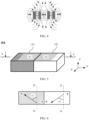
- FIG. 1 to FIG. 4 show several magnetic field distributions after combination of two strip magnets.
- FIG. 1 shows a magnetic line distribution when different polarities of the two strip magnets face each other.
- FIG. 2 shows a magnetic line distribution when same polarities of the two strip magnets face each other.
- FIG. 3 shows a magnetic line distribution when different polarities of the two strip magnets are parallel.
- FIG. 4 shows a magnetic line distribution when same polarities of the two strip magnets are parallel. It can be seen from the figures that the two magnets are surrounded by magnetic lines. When these magnets are used in an electronic device, magnetic fields around the magnets have adverse impact on normal operation of electronic components at various locations around the magnets. In addition, because the magnetic fields generated by the magnets are dispersed, magnetic lines in main working directions of the magnets are not sufficiently aggregated, and working performance of the magnets is limited.
- this application provides a first magnet 10.
- a direction of a magnetic line inside the magnet is inclined toward a normal direction of a plane on which the magnet is located. More magnetic lines may be aggregated in upper space or lower space of the plane on which the magnet is located. In a same case, an interaction force generated between the magnet and another magnet is greater.
- FIG. 5 is a diagram of a structure of a first magnet 10A.
- FIG. 6 is a diagram of an AA cross section of the first magnet 10A.
- FIG. 7 is a diagram of a magnetic line distribution around the first magnet 10A.
- the first magnet 10A includes a first sub-magnet 110 and a second sub-magnet 120, and the first sub-magnet 110 and the second sub-magnet 120 are adjacently disposed.
- a direction of a magnetic line inside the first sub-magnet 110 is inclined toward a normal direction (an OO direction in FIG. 6 ) of a plane on which the first magnet 10A is located.
- an included angle between the direction of the magnetic line inside the first sub-magnet 110 and the normal direction of the plane on which the first magnet 10A is located is ⁇ 1, where 0 ⁇ 1 ⁇ 90°.
- the foregoing description related to the direction of the magnetic line inside the first sub-magnet 110 may also be understood as that a magnetization direction on an AA cross section of the first sub-magnet 110 is at an acute angle to the plane on which the first magnet 10A is located, or the magnetization direction on the AA cross section of the first sub-magnet 110 is at an included angle of (90°- ⁇ 1) to the plane on which the first magnet 10A is located, where 0 ⁇ 1 ⁇ 90°.
- a direction of a magnetic line inside the second sub-magnet 120 is inclined toward the normal direction (the OO direction in FIG. 6 ) of the plane on which the first magnet 10A is located.
- an included angle between the direction of the magnetic line inside the second sub-magnet 120 and the normal direction of the plane on which the first magnet 10A is located is ⁇ 2, where 0 ⁇ 2 ⁇ 90°.
- a magnetization direction on an AA cross section of the second sub-magnet 120 is at an acute angle to the plane on which the first magnet 10 is located, or the magnetization direction on the AA cross section of the second sub-magnet 120 is at an included angle of (90°- ⁇ 2) to the plane on which the first magnet 10 is located, where 0 ⁇ 2 ⁇ 90°.
- magnetic lines around the first magnet 10A are mainly aggregated in upper space of an upper surface of the first magnet 10A, and the upper surface of the first magnet 10A may also be referred to as a working face of the first magnet 10A.
- N and S polarities in adjacent regions of the first sub-magnet 110 and the second sub-magnet 120 on the working face (or referred to as an attraction face or a repulsion face) of the first magnet 10A are opposite.
- an N or S polarity in an A1 region of the first sub-magnet 110 and an N or S polarity in an A2 region of the second sub-magnet 120 are opposite.
- magnetic poles of the first sub-magnet 110 and the second sub-magnet 120 that are opposite to each other are adjacently disposed, and are disposed close to a same face of the first magnet 10A.
- an upper left corner of the first sub-magnet 110 is represented as an N pole attribute, and a lower right corner of the first sub-magnet 110 is represented as an S pole attribute.
- an upper right corner of the second sub-magnet 120 is represented as an S pole attribute, and a lower left corner of the second sub-magnet 120 is represented as an N pole attribute.
- the included angle ⁇ 1 is equal to the included angle ⁇ 2.
- an included angle between the direction of the magnetic line inside the first sub-magnet 110 and the direction of the magnetic line inside the second sub-magnet 120 is 180°-( ⁇ 1+ ⁇ 2).
- the direction of the magnetic line inside the first sub-magnet 110 points to the working face
- the direction of the magnetic line inside the second sub-magnet 120 points to another face opposite to the working face.
- a shape and a size of the first sub-magnet 110 may be basically consistent with a shape and a size of the second sub-magnet 120.
- a width of the first sub-magnet 110 may be equal to a width of the second sub-magnet 120, that is, the first sub-magnet 110 and the second sub-magnet 120 have an equal size in a Y-axis direction in FIG. 5 .
- a height of the first sub-magnet 110 may be equal to a height of the second sub-magnet 120, that is, the first sub-magnet 110 and the second sub-magnet 120 have an equal size in a Z-axis direction in FIG. 5 .
- the shape and the size of the first sub-magnet 110 are basically consistent with the shape and the size of the second sub-magnet 120, superposition of magnetic lines generated by the first sub-magnet 110 and magnetic lines generated by the second sub-magnet 120 results in a sparser distribution of the magnetic lines around the first magnet 10A and a denser distribution of the magnetic lines in the upper space and/or the lower space of the first magnet 10A. In this way, when the working face of the first magnet 10A is used to interact with another magnet, an interaction force generated between the first magnet 10A and the another magnet is stronger, and the first magnet 10 has smaller adverse impact on normal running of surrounding electronic components.
- a direction of a magnetic line inside the first magnet 10A is changed, that is, a magnetization direction inside the first magnet 10A is changed, so that more magnetic lines can be aggregated in space corresponding to the working face of the first magnet 10A, the first magnet 10A having fewer materials and a smaller volume can generate a magnetic line distribution similar to that generated by a magnet having more materials and a larger volume, thereby reducing occupied space of the first magnet and reducing material costs of the first magnet.
- the first magnet may further have other different shapes.
- the first sub-magnet 110 and the second sub-magnet 120 included in the first magnet may also have different shapes.
- FIG. 8 and FIG. 9 are top views of first magnets of two different shapes as examples.
- a first magnet 10B may be in a truncated pyramid shape, a first sub-magnet 110 and a second sub-magnet 120 are also truncated pyramids, and the first sub-magnet 110 and the second sub-magnet 120 jointly form the first magnet 10B.
- the cross section shown in FIG. 6 may be considered as a BB cross section of an isosceles trapezoid in FIG. 8 .
- a left isosceles trapezoid is the first sub-magnet 110
- a right isosceles trapezoid is the second sub-magnet 120.
- the first sub-magnet 110 is connected to the second sub-magnet 120.
- a contact face between the first sub-magnet 110 and the second sub-magnet 120 may be referred to as a first contact face
- a contact face between the second sub-magnet 120 and the first sub-magnet 110 may be referred to as a second contact face.
- shapes and sizes of the first contact face and the second contact face are consistent.
- An outer surface of the first sub-magnet 110 adjacent to the first contact face may be referred to as a side wall of the first sub-magnet 110, another outer surface of the first sub-magnet 110 opposite to the first contact face may be referred to as a first exposed face of the first sub-magnet 110, and the first contact face and the first exposed face may be respectively considered as an upper bottom face and a lower bottom face of the first sub-magnet 110.
- an outer surface of the second sub-magnet 120 adjacent to the second contact face may be referred to as a side wall of the second sub-magnet 120
- another outer surface of the second sub-magnet 120 opposite to the second contact face may be referred to as a second exposed face of the second sub-magnet 120
- the second exposed face and the second contact face may be respectively considered as an upper bottom face and a lower bottom face of the second sub-magnet 120.
- two included angles between the first contact face of the first sub-magnet 110 and a plane on which the side wall is located are respectively equal to two included angles between the second contact face of the second sub-magnet 120 and a plane on which the side wall is located.
- the side wall of the first sub-magnet 110 and the side wall of the second sub-magnet 120 smoothly transit at a location at which the side wall of the first sub-magnet 110 and the side wall of the second sub-magnet 120 are connected.
- first exposed face, the first contact face, the second contact face, and the second exposed face of the first magnet 10B may be disposed in parallel.
- shapes of the first sub-magnet 110 and the second sub-magnet 120 may be basically consistent.
- a width of the first sub-magnet 110 may be equal to a width of the second sub-magnet 120.
- a distance between the first contact face and the first exposed face of the first sub-magnet 110 is equal to a distance between the second contact face and the second exposed face of the second sub-magnet 120.
- a first magnet 10C may be in an axisymmetrical sector ring shape, a first sub-magnet 110 and a second sub-magnet 120 are also axisymmetrical sector rings, and the first sub-magnet 110 and the second sub-magnet 120 jointly form the first magnet 10C.
- the cross section shown in FIG. 6 may be a CC cross section of a sector ring in FIG. 9 .
- a left sector ring may be considered as the first sub-magnet 110
- a right sector ring may be considered as the second sub-magnet 120.
- the first sub-magnet 110 is connected to the second sub-magnet 120.
- a contact face between the first sub-magnet 110 and the second sub-magnet 120 may be referred to as a first contact face
- a contact face between the second sub-magnet 120 and the first sub-magnet 110 may be referred to as a second contact face.
- shapes and sizes of the first contact face and the second contact face are consistent.
- the first sub-magnet 110 in the sector ring shape is located on an outer side of the second sub-magnet 120 in the sector ring shape.
- a cambered face of the first sub-magnet 110 close to the second sub-magnet 120 may be referred to as a first inner wall, and a cambered face of the first sub-magnet 110 away from the second sub-magnet 120 may be referred to as a first outer wall.
- a cambered face of the second sub-magnet 120 close to the first sub-magnet 110 may be referred to as a second outer wall, and a cambered face of the second sub-magnet 120 away from the first sub-magnet 110 may be referred to as a second inner wall. Shapes and sizes of the first inner wall and the second outer wall are equal.
- shapes of the first sub-magnet 110 and the second sub-magnet 120 may be basically consistent.
- a width of the first sub-magnet 110 is equal to a width of the second sub-magnet 120.
- a difference between an outer diameter and an inner diameter of a sector ring corresponding to the first sub-magnet 110 is equal to a difference between an outer diameter and an inner diameter of a sector ring corresponding to the second sub-magnet 120.
- the first magnet 10A in a cuboid shape shown in FIG. 5 , the first magnet 10B in a truncated pyramid shape shown in FIG. 8 , and the first magnet 10C in a sector ring shape shown in FIG. 9 are used as structural units for splicing, to obtain different spliced shapes.
- the first magnets 10A in a cuboid shape are used as structural units, and may be spliced into a first magnet group 200 in a strip shape or a second magnet group 310 in a polygon shape.
- the second magnet group 310 in the polygon shape shown in FIG. 11 may be in an approximately ring shape.
- a plurality of first magnets 10A may be spliced into an approximately non-closed ring shape.
- a notch may be disposed in the second magnet group 310 in the approximately ring shape shown in FIG. 11 .
- the non-closed ring may be in an axisymmetrical shape.
- a plurality of first magnets 10A may be inconsecutively axisymmetrically distributed to form a magnet group, and the magnet group may include an even quantity or an odd quantity of first magnets 10A.
- the first magnets 10B in a truncated pyramid shape are used as structural units, and may be spliced into a third magnet group 320 in a polygon shape.
- the third magnet group 320 in the polygon shape shown in FIG. 12 is in an approximately ring shape.
- a plurality of first magnets 10B may be spliced into an approximately non-closed ring shape.
- a notch may be disposed in the third magnet group 320 in the approximately ring shape shown in FIG. 12 .
- the non-closed ring may be in an axisymmetrical shape.
- a plurality of first magnets 10B may be inconsecutively axisymmetrically distributed to form a magnet group, and the magnet group may include an even quantity or an odd quantity of first magnets 10B.
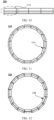
- first magnets 10C in a sector ring shape are used as structural units, and may be spliced into a fourth magnet group 330 in a ring shape.
- a plurality of first magnets 10C may be spliced into an approximately non-closed ring shape, that is, a fifth magnet group 331 shown in FIG. 14 .
- the fifth magnet group 331 may be axisymmetrical about a symmetry axis WW.
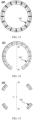
- the plurality of first magnets 10C may be inconsecutively axisymmetrically distributed to form a sixth magnet group 332 shown in FIG. 15 .
- the sixth magnet group 332 may include an even quantity or an odd quantity of first magnets 10C, and the plurality of first magnets 10C may be axisymmetrically distributed about the symmetry axis WW.
- the plurality of first magnets 10C may alternatively be centrosymmetrically distributed, for example, with respect to a symmetrical central point C in FIG. 15 .
- first magnets of a same type are combined by first magnets of a same type, distributions of magnetic lines at all locations on the ring are basically consistent.
- first magnets of a same shape but different properties are used as structural units, and may be combined to form rings with different magnetic line distribution statuses at different locations on a ring face.
- FIG. 16 and FIG. 17 provide two examples.
- Combined magnets in ring shapes in FIG. 16 and FIG. 17 include two structural units of a same shape but different properties: a first structural unit 21 and a second structural unit 22.
- the first structural unit 21 and the second structural unit 22 have a similar shape to the first magnet 10C in the sector ring shape.
- the first structural unit 21 includes a first structural subunit and a second structural subunit.
- the first structural subunit is located on an outer side of the second structural subunit, and both the first structural subunit and the second structural subunit are in an approximately sector ring shape.
- a shape of the first structural subunit and a direction of an internal magnetic line are consistent with the shape of the first sub-magnet 110 and the direction of the internal magnetic line in FIG. 9
- a shape of the second structural subunit and a method of an internal magnetic line are consistent with the shape of the second sub-magnet 120 and the direction of the internal magnetic line in FIG. 9 .
- the first structural subunit and the second structural subunit refer to related content in FIG. 9 .
- details are not described herein again.
- the second structural unit 22 includes a third structural subunit and a fourth structural subunit.
- the third structural subunit is located on an outer side of the fourth structural subunit, and both the third structural subunit and the fourth structural subunit are in an approximately sector ring shape.
- a shape of the third structural subunit is consistent with the shape of the first sub-magnet 110 in FIG. 9 , and a direction of a magnetic line inside the third structural subunit is consistent with the direction of the magnetic line inside the second sub-magnet 120 in FIG. 9 .
- a shape of the fourth structural subunit is consistent with the shape of the second sub-magnet 120 in FIG. 9 , and a direction of a magnetic line inside the fourth structural subunit is consistent with the direction of the magnetic line inside the first sub-magnet 110 in FIG. 9 .
- For related descriptions of the third structural subunit and the fourth structural subunit refer to related content in FIG. 9 . For brevity, details are not described herein again.
- the first structural unit 21 and the second structural unit 22 are alternately arranged to form a seventh magnet group 334.
- a combined magnet ring is assembled in an arrangement manner in which two first structural units 21 are spaced by two second structural units 22, to form an eighth magnet group 335.
- a direction of a magnetic line in upper space of a working face of the first structural unit 21 faces a first direction
- a magnetic direction in upper space of a working face of the second structural unit 22 is away from the first direction.
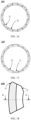
- FIG. 18 , FIG. 19 , and FIG. 22 are main views of some first magnets in non-mirror-symmetrical shapes as examples.
- a fillet or a chamfer is separately disposed on different portions of two sub-magnets of the first magnet 10C in a sector ring shape, and a splicing sequence of the first magnets 10C may be determined based on locations of reverse angles.
- FIG. 18 is a diagram of a first magnet 10D.
- a first reverse angle 31 may be disposed near a connection location between a first outer wall and a side wall of a first sub-magnet 110 located at a left side
- a second reverse angle 32 may be disposed near a connection location between a second inner wall and a side wall of a second sub-magnet 120 located at a right side.
- the first reverse angle 31 and the second reverse angle 32 may be located on a side wall at a same side of the first magnet 10D.
- FIG. 19 is a diagram of a first magnet 10E.
- a third reverse angle 33 may be disposed near a connection location between a first outer wall and a side wall of a first sub-magnet 110 located at a left side
- a fourth reverse angle 34 may be disposed near a connection location between a second inner wall and a side wall of a second sub-magnet 120 located at a right side.
- the third reverse angle 33 and the fourth reverse angle 34 may be located on side walls at different sides of the first magnet 10E.
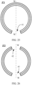
- FIG. 20 shows a ninth magnet group 340 that is in an approximately ring shape and that is formed by splicing and assembling the first magnets 10D in FIG. 18 .
- FIG. 21 shows a tenth magnet group 350 that is in an approximately ring shape and that is formed by splicing and assembling the first magnets 10E in FIG. 19 .
- a first sub-magnet ring located on an outer side of the ninth magnet group 340 and the tenth magnet group 350 is obtained by splicing first sub-magnets 110 located in the first magnets 10D or the first magnets 10E, and a second sub-magnet ring located on an inner side of the magnet groups is obtained by splicing second sub-magnets 120 located in the first magnets 10D or the first magnets 10E.
- two side walls of first magnets with different tilt angles may be disposed, so that an installation sequence of the first magnets can be determined based on different side walls.
- a connection line between midpoints of two side walls of a first magnet 10F is used as a reference line.
- An included angle formed between a first side wall of the first magnet 10F and the reference line is ⁇ 1.
- An included angle formed between a second side wall of the first magnet 10F and the reference line is ⁇ 2.
- the included angle ⁇ 1 and the included angle ⁇ 2 may respectively reflect a tilt degree of the first side wall and a tilt degree of the second side wall.
- a difference between the two included angles may be appropriately increased, to increase a difference between the tilt degree of the first side wall and the tilt degree of the second side wall, reduce a probability that an installation sequence of the first magnet 10F is reversed, and improve efficiency of splicing and assembling a plurality of first magnets 10F.
- the difference between the tilt degrees of the first side wall and the second side wall may alternatively be described by using another reference line or reference plane.
- a central plane determined by using a middle line of a lower bottom face on the first magnet 10F is used as a reference plane, and included angles between the first side wall and the reference plane and between the second side wall and the reference plane are separately observed, to determine the tilt degrees of the first side wall and the second side wall.
- the plurality of first magnets 10F are spliced in a manner in which two side walls with different tilt degrees of two adjacent magnets press against each other, to obtain an eleventh magnet group 360 in an approximately ring shape shown in FIG. 23 .
- first magnets may alternatively be of more other asymmetric structures.
- a working face and a connection face of the first magnet are two asymmetric faces
- a reverse angle is disposed at a joint between an exposed face and the working face of the first magnet
- a reverse angle is disposed at a joint between a contact face and the connection face of the first magnet
- a left side wall and a right side wall of the first magnet are coated with coatings in different colors. This is not limited in this application.
- first sub-magnets 110 in the first magnets 10F are connected to each other to form a first sub-magnet ring on an outer side of a combined magnet
- second sub-magnets 120 in the first magnets 10F are connected to each other to form a second sub-magnet ring on an inner side of the combined magnet.
- a first magnet 10G may be in a ring shape.
- a first sub-magnet 110 and a second sub-magnet 120 included in the first magnet 10G may also be in a ring shape.
- the first sub-magnet 110 is located on an outer side of the second sub-magnet 120, and an inner radius of the first sub-magnet 110 is equal to an outer radius of the second sub-magnet 120.
- shapes of the first sub-magnet 110 and the second sub-magnet 120 may be basically consistent.
- a width of the first sub-magnet 110 in the ring shape is equal to a width of the second sub-magnet 120 in the ring shape.
- the cross section shown in FIG. 6 may be a GG cross section of the first magnet in the ring shape in FIG. 24 in a direction of a diameter of a ring.
- the first magnet 10G in the ring shape may include a plurality of first magnetic portions and a plurality of second magnetic portions that are spaced apart, and directions of magnetic lines of the first magnetic portion and the second magnetic portion at one side of the first magnet 10G are opposite.
- a structure of the first magnetic portion may be similar to a structure of the first structural unit 21 shown in FIG. 16 or FIG. 17
- a structure of the second magnetic portion may be similar to a structure of the second structural unit 22 shown in FIG. 16 or FIG. 17 .
- details are not described herein again.
- Magnetic lines in different directions on a ring face of the magnet ring are alternately distributed.
- the first magnet 10G in the ring shape and another magnet in a ring shape are used for mutual repulsion or attraction, the first magnetic portion and the another magnet show an attraction force, the second magnetic portion and the same magnet show a repulsion force, and the combined magnet ring interacts with the another magnet, the two magnetic portions with opposite magnetic line directions can select an angle for interaction.
- One or more notches may be disposed in the first magnet 10G in the ring shape.
- a first notch 41 is disposed in the first magnet 10G in the ring shape.
- the following two axisymmetrically distributed notches may be disposed in the first magnet 10G in the ring shape: a second notch 42 and a third notch 43.
- the first magnet 10G in the ring shape may include two axisymmetrically distributed sector rings.
- the following three centrosymmetrically distributed notches may be disposed in the first magnet 10G in the ring shape: a fourth notch 44, a fifth notch 45, and a sixth notch 46.
- the first magnet 10G in the ring shape may include three centrosymmetrical sector rings.
- the first magnet 10G in the ring shape may be prepared according to an integrated molding process.
- One or more notches disposed in the first magnet 10G may be configured to connect an internal region enclosed by the first magnet 10G in the ring shape and an external region.
- the one or more notches may be configured to accommodate a line connecting an electronic component located in the internal region of the first magnet 10G and an electronic component outside the first magnet 10G or the like.
- a backplane 30 may be disposed in the foregoing first magnets of various types, and the backplane 30 may be configured to relatively fasten the first sub-magnet 110 and the second sub-magnet 120 in the first magnet.
- the backplane 30 may be disposed on a face with sparse magnetic lines of the first magnet.
- the face with sparse magnetic lines of the first magnet may be fastened to the backplane 30.
- locations of the first sub-magnet 110 and the second sub-magnet 120 that form the first magnet are also relatively fastened.
- a shape of the backplane 30 may be determined based on a shape of the first magnet.
- the first magnet is in a ring shape, or a plurality of first magnets may form a ring shape, a polygon shape, or the like.
- a width of the backplane 30 in the ring shape should be slightly greater than a width of the first magnet, so that a projection of the first magnet in the plane on which the backplane 30 is located can fall within a range of the backplane 30.
- the first magnet is the cuboid shown in FIG. 5
- the backplane may also be a cuboid plate structure.
- the backplane 30 may alternatively be made of a material whose magnetic permeability is greater than a preset threshold, for example, a ferro-magnetic material or a soft magnetic material.
- a magnetic line emitted by the first magnet may be preferentially closed by using the magnetically conductive backplane 30 with a smaller magnetic resistance, thereby helping weaken a magnetic field at one side of the backplane 30, enhancing a magnetic field of a working face, and helping increase an interaction force between the first magnet and another magnet.
- FIG. 29 to FIG. 34 are diagrams of structures and corresponding cross sections of several magnet ring pairs according to embodiments of this application.
- the magnet ring pair includes a first magnet ring and a second magnet ring that fit with each other. There may be a mutual attraction force between the first magnet ring and the second magnet ring, or there may be a mutual repulsion force between the first magnet ring and the second magnet ring. The following describes an example in which the two magnet rings are attracted to each other.
- a structure of at least one of the first magnet ring and the second magnet ring is similar to the structure of the first magnet in the ring shape or the magnet group in the ring shape formed by the plurality of first magnets in the foregoing embodiments, thereby helping enhance the interaction force between the two magnet rings.
- Structures of first magnet rings in FIG. 29 to FIG. 34 are basically similar. The following first describes the structures of the first magnet rings.
- the structure of the first magnet ring 500 is similar to that of the first magnet 10G in the ring shape in the foregoing embodiment.
- the first magnet ring 500 includes a first sub-magnet ring and a second sub-magnet ring.
- the first sub-magnet ring is located on an outer side of the second sub-magnet ring, and an inner wall of the first sub-magnet ring is in contact with an outer wall of the second sub-magnet ring.
- an inner diameter of the first sub-magnet ring is basically equal to an outer diameter of the second sub-magnet ring.
- a PP cross section of the first magnet ring 500 in a radial direction is shown in FIG. 30 .
- a rectangle at a left side corresponds to a cross section of the first sub-magnet ring
- a rectangle at a right side corresponds to a cross section of the second sub-magnet ring.
- Directions of arrows in the two rectangles may respectively indicate a direction of a magnetic line inside the first sub-magnet ring and a direction of a magnetic line inside the second sub-magnet ring.
- the direction of the magnetic line inside the first sub-magnet ring is inclined toward an axial direction of the first magnet ring 500.
- the direction of the magnetic line inside the first sub-magnet ring is inclined toward a normal direction of a plane on which the first magnet ring 500 is located.
- the direction of the magnetic line inside the second sub-magnet ring is inclined toward an axial direction of the first magnet ring 500.
- the direction of the magnetic line inside the second sub-magnet ring is inclined toward a normal direction of a plane on which the first magnet ring 500 is located.
- an included angle between the direction of the magnetic line inside the first sub-magnet ring and the axial direction of the first magnet ring 500 is ⁇ 1
- an included angle between the direction of the magnetic line inside the second sub-magnet ring and the axial direction of the first magnet ring 500 is ⁇ 2.
- a value range of ⁇ 1 is 0 ⁇ 1 ⁇ 90°
- a value range of ⁇ 2 is 0 ⁇ 2 ⁇ 90°.
- a value range of ⁇ 1 may be set to 0 ⁇ 1 ⁇ 60°, for example, 15°, 30°, 45°, or 60°.
- a value range of ⁇ 2 may be set to 0 ⁇ 2 ⁇ 60°, for example, 15°, 30°, 45°, or 60°.
- Magnetic poles at two sides of a contact face of the first sub-magnet ring and the second sub-magnet ring may be opposite, so that more magnetic lines can be distributed near a face of the first magnet ring 500 close to the second magnet ring 600.
- an S pole of the first sub-magnet ring may be adjacent to or in contact with an N pole of the second sub-magnet ring, or an N pole of the first sub-magnet ring may be adjacent to or in contact with an S pole of the second sub-magnet ring.
- Adjusting a relationship between the direction of the magnetic line inside the first sub-magnet ring and the direction of the magnetic line inside the second sub-magnet ring can further improve the distribution of the magnetic lines of the first magnet ring 500, and increase the interaction force between the first magnet ring 500 and the second magnet ring 600.
- ⁇ 1- ⁇ 2 ⁇
- a value range of ⁇ is -5° ⁇ 5°, for example, -5°, -3°, 0°, 3°, or 5°.
- a width of the first sub-magnet ring may be equal to a width of the second sub-magnet ring. In other words, widths of the two rectangles at the left side and the right side of the cross section of the first magnet ring 500 are equal.
- the width of the first sub-magnet ring is set to be equal to the width of the second sub-magnet ring, so that magnetic lines of the first sub-magnet ring and magnetic lines of the second sub-magnet ring that are located at an inner side and an outer side of the first magnet ring 500 can counteract each other as far as possible, and magnetic lines of the first sub-magnet ring located at a face of the first magnet ring 500 close to the second magnet ring 600 and the magnetic lines of the second sub-magnet ring can be superimposed. Therefore, an interaction force between the first magnet ring 500 and the second magnet ring 600 can be enhanced.
- a third sub-magnet ring may be further disposed between the first sub-magnet ring and the second sub-magnet ring.
- a direction of a magnetic line inside the third sub-magnet ring may be in the radial direction of the first magnet ring 500.
- the direction of the magnetic line inside the third sub-magnet ring may be perpendicular to the normal direction of the plane on which the first magnet ring 500 is located.
- An N pole in the third sub-magnet ring may be disposed close to an S pole of the first sub-magnet ring, and an S pole in the third sub-magnet ring may be disposed close to an N pole of the second sub-magnet ring.
- the first magnet ring 500 may further include a fourth sub-magnet ring and a fifth sub-magnet ring.
- the fourth sub-magnet ring may be located on an outer side of the fifth sub-magnet ring.
- An inner wall of the fourth sub-magnet ring is in contact with an outer wall of the fifth sub-magnet ring.
- An outer wall of the fourth sub-magnet ring is in contact with an inner wall of the second sub-magnet ring.
- the first magnet ring 500 may be considered as a concentric ring structure formed by sequentially nesting the first sub-magnet ring, the second sub-magnet ring, the fourth sub-magnet ring, and the fifth sub-magnet ring.
- a structure of the fourth sub-magnet ring is similar to a structure of the first sub-magnet ring, and a structure of the fifth sub-magnet ring is similar to a structure of the second sub-magnet ring.
- a structure of the fourth sub-magnet ring and the structure of the fifth sub-magnet ring refer to the descriptions related to the structure of the first sub-magnet ring and the structure of the second sub-magnet ring. For brevity, details are not described herein again.
- a structure of a coupled magnet ring interacting with the first magnet ring 500 may be determined based on a type of interaction between the two magnet rings. In some examples, there is a mutual attraction force between the first magnet ring 500 and the coupled magnet ring.
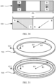
- FIG. 29 and FIG. 30 further show a structure of a second magnet ring 600 coupled to the first magnet ring 500 and a radial cross section thereof.
- the second magnet ring 600 may include a sixth sub-magnet ring 610 and a seventh sub-magnet ring 620.
- the sixth sub-magnet ring 610 is located at an outer side of the seventh sub-magnet ring 620, and the sixth sub-magnet ring 610 and the seventh sub-magnet ring 620 are spaced apart.
- an inner diameter of the sixth sub-magnet ring 610 is greater than an outer diameter of the seventh sub-magnet ring 620.
- a spacing region may be disposed between the sixth sub-magnet ring 610 and the seventh sub-magnet ring 620, and the spacing region may also be referred to as a magnetic-free region.
- both a direction of a magnetic line inside the sixth sub-magnet ring 610 located at the outer side and a direction of a magnetic line inside the seventh sub-magnet ring 620 located at the inner side are parallel to an axial direction of the second magnet ring 600.
- the direction of the magnetic line inside the sixth sub-magnet ring 610 is opposite to the direction of the magnetic line inside the seventh sub-magnet ring 620.
- an S pole of the sixth sub-magnet ring 610 is disposed close to an N pole of the first sub-magnet ring
- an N pole of the sixth sub-magnet ring 610 is disposed far away from the N pole of the first sub-magnet ring
- an N pole of the seventh sub-magnet ring 620 is disposed close to an S pole of the second sub-magnet ring
- an S pole of the seventh sub-magnet ring 620 is disposed far away from the S pole of the second sub-magnet ring.
- a shape of the first magnet ring 500 may match a shape of the second magnet ring 600.
- a distance R1 between a ring center O1 of the first magnet ring 500 and a central line of the cross section of the magnet ring and a distance R2 between a ring center O2 of the second magnet ring 600 and a central line of the cross section of the magnet ring should be basically equal.
- a difference ⁇ between R1 and R2 should be less than a preset threshold.
- a matching relationship between the shape of the first magnet ring 500 and the shape of the second magnet ring 600 may also be understood as that the two cross sections of the first magnet ring 500 and the second magnet ring 600 at a same location are axisymmetric about a same straight line. In other words, the center lines of the two cross sections overlap.
- D1 and D2 respectively indicate a width of the first magnet ring 500 and a width of the second magnet ring 600.
- D2 ⁇ D1. Because both the magnetic line inside the first sub-magnet ring and the magnetic line inside the second sub-magnet ring are obliquely disposed, the wider second magnet ring 600 helps enable more magnetic lines emitted by the first magnet ring 500 to enter the second magnet ring 600, and also helps enable more magnetic lines emitted by the second magnet ring 600 to enter the first magnet ring 500, thereby helping increase the interaction force between the first magnet ring 500 and the second magnet ring 600.
- the width of the second magnet ring 600 may be determined based on the included angle ⁇ 1 between the direction of the magnetic line inside the first sub-magnet ring and the axial direction of the first magnet ring 500 and the included angle ⁇ 2 between the direction of the magnetic line inside the second sub-magnet ring and the axial direction of the first magnet ring 500.
- the second magnet ring 600 may be provided with a larger magnet ring width, thereby helping enhance the interaction force between the two magnet rings.
- FIG. 31 and FIG. 32 are respectively a diagram of another structure of a third magnet ring 700 coupled to the first magnet ring 500 and a diagram of a radial cross section thereof.
- a direction of a magnetic line inside the third magnet ring 700 is a radial direction of the third magnet ring 700.
- the direction of the magnetic line inside the third magnet ring 700 is perpendicular to a normal direction of a plane on which the third magnet ring 700 is located.
- an S pole in the third magnet ring 700 may be disposed close to an N pole of the first sub-magnet ring, and an N pole in the third magnet ring 700 may be disposed close to an S pole of the second sub-magnet ring.
- the S pole in the third magnet ring 700 may be located on an outer side of the third magnet ring 700
- the N pole in the third magnet ring 700 may be located on an inner side of the third magnet ring 700.
- a shape of the first magnet ring 500 may match a shape of the third magnet ring 700.
- a distance R1 between a ring center O1 of the first magnet ring 500 and a central line of the cross section of the magnet ring and a distance R3 between a ring center O3 of the third magnet ring 700 and a central line of the cross section of the magnet ring should be basically equal.
- a difference ⁇ between R1 and R3 should be less than a preset threshold.
- a matching relationship between the shape of the first magnet ring 500 and the shape of the third magnet ring 700 may also be understood as that the two cross sections of the first magnet ring 500 and the third magnet ring 700 at a same location are axisymmetric about a same straight line. In other words, the center lines of the two cross sections overlap.
- FIG. 32 is a diagram of a radial QQ cross section of the third magnet ring 700.
- D1 and D3 respectively indicate a width of the first magnet ring 500 and a width of the third magnet ring 700. In some examples, D3 ⁇ D1. Because both the magnetic line inside the first sub-magnet ring and the magnetic line inside the second sub-magnet ring are obliquely disposed, the wider third magnet ring 700 helps enable more magnetic lines emitted by the first magnet ring 500 to enter the third magnet ring 700, and also helps enable more magnetic lines emitted by the third magnet ring 700 to enter the first magnet ring 500, thereby helping increase the interaction force between the first magnet ring 500 and the third magnet ring 700.
- the width of the third magnet ring 700 may be determined based on the included angle ⁇ 1 between the direction of the magnetic line inside the first sub-magnet ring and the axial direction of the first magnet ring 500 and the included angle ⁇ 2 between the direction of the magnetic line inside the second sub-magnet ring and the axial direction of the first magnet ring 500.
- the third magnet ring 700 may be provided with a larger magnet ring width, thereby helping enhance the interaction force between the two magnet rings.
- FIG. 33 and FIG. 34 are respectively a diagram of still another structure of a fourth magnet ring 800 coupled to the first magnet ring 500 and a diagram of a radial cross section thereof.
- the structure of the fourth magnet ring 800 is similar to the structure of the first magnet ring 500.
- the fourth magnet ring 800 includes an eighth sub-magnet ring 810 and a ninth sub-magnet ring 820.
- the eighth sub-magnet ring 810 is located on an outer side of the ninth sub-magnet ring 820, and an inner wall of the eighth sub-magnet ring 800 may be in contact with an outer wall of the ninth sub-magnet ring 900.
- an inner diameter of the eighth sub-magnet ring 800 is basically equal to an outer diameter of the ninth sub-magnet ring 900.
- a direction of a magnetic line inside the eighth sub-magnet ring 810 is inclined toward a normal direction of a plane on which the fourth magnet ring 800 is located
- a direction of a magnetic line inside the ninth sub-magnet ring 820 is inclined toward a normal direction of the plane on which the fourth magnet ring 800 is located.
- An S pole in the eighth sub-magnet ring 810 is disposed close to the N pole of the first sub-magnet ring
- an N pole in the ninth sub-magnet ring 820 is disposed close to the S pole of the second sub-magnet ring
- an N pole of the eighth sub-magnet ring 810 is disposed close to an S pole of the ninth sub-magnet ring 820.
- a structure of the eighth sub-magnet ring 810 and a structure of the ninth sub-magnet ring 820 are similar to the structures of the first sub-magnet ring and the second sub-magnet ring.
- a structure of the eighth sub-magnet ring 810 and a structure of the ninth sub-magnet ring 820 are similar to the structures of the first sub-magnet ring and the second sub-magnet ring.
- FIG. 29 and FIG. 30 For detailed descriptions, refer to related content in FIG. 29 and FIG. 30 . For brevity, details are not described herein again.
- a shape of the first magnet ring 500 may match a shape of the fourth magnet ring 800.
- a distance R1 between a ring center O1 of the first magnet ring 500 and a central line of the cross section of the magnet ring and a distance R4 between a ring center O4 of the fourth magnet ring 800 and a central line of the cross section of the magnet ring should be basically equal.
- a difference ⁇ between R1 and R4 should be less than a preset threshold.
- a matching relationship between the shape of the first magnet ring 500 and the shape of the fourth magnet ring 800 may also be understood as that the two cross sections of the first magnet ring 500 and the fourth magnet ring 800 at a same location are axisymmetric about a same straight line. In other words, the center lines of the two cross sections overlap.
- FIG. 34 is the diagram of a radial UU cross section of the fourth magnet ring 800. Because the directions of the magnetic lines inside the first sub-magnet ring, the second sub-magnet ring, the eighth sub-magnet ring 810, and the ninth sub-magnet ring 820 are all obliquely disposed, to increase the interaction force between the first magnet ring 500 and the fourth magnet ring 800, the width of the first magnet ring 500 and a width of the fourth magnet ring 800 should be as equal as possible.
- a backplane may also be disposed on a connection face on another side opposite to the working faces of the first sub-magnet ring and the second sub-magnet ring in the first magnet ring 500.
- the backplane may be made of a material whose magnetic permeability is greater than the preset threshold, for example, a ferro-magnetic material or a soft magnetic material.
- Disposing a backplane structure can relatively fasten two sub-magnet rings located inside a same magnet ring, and can enable magnetic lines between the two sub-magnet rings to be closed by using a backplane structure with good magnetic conductivity, thereby helping improve magnetic line density emitted by the first magnet ring 500, and helping increase interaction forces between the first magnet ring 500 and the second magnet ring, the third magnet ring, or the fourth magnet ring.
- the first magnet ring 500 provided in embodiments of this application is applicable to different application scenarios.
- FIG. 35 and FIG. 36 provide two application methods of the first magnet ring 500 as examples. It should be understood that the first magnet ring 500 may be further applied to a scenario other than FIG. 35 and FIG. 36 , for example, a magnetic protective case of an electronic device or a magnetic mobile power pack. This is not limited in this application.
- FIG. 35 shows a wireless charging cradle 2000 according to an embodiment of this application.
- the wireless charging cradle 2000 may include a cover 2100 and a housing 2200.
- the cover 2100 may cover the housing 2200.
- the cover 2100 and the housing 2200 may enclose accommodation space.
- the accommodation space may accommodate a first connection ring 2300 and a charging coil 2400 of the wireless charging cradle 2000.
- the first connection ring 2300 may be any first magnet ring provided above.
- the charging coil 2400 is disposed inside a region enclosed by the first connection ring 2300, and the charging coil 2400 is further connected to a circuit board in the wireless charging cradle 2000.
- the circuit board is disposed outside the region enclosed by the first connection ring 2300.
- a notch may be disposed in the first connection ring 2300, and an interconnection line connecting the charging coil 2400 and the circuit board may connect the charging coil 2400 inside the first connection ring to the circuit board outside the first connection ring 2300 through the notch.
- the first connection ring 2300 in the wireless charging cradle 2000 may fit with a coupled connection ring installed on an electronic device. There may be a mutual magnetic attraction force between the first connection ring 230 and the coupled connection ring.
- the mutual attraction force between the first connection ring 2300 and the coupled connection ring on the electronic device may attract the electronic device to the wireless charging cradle 2000. Therefore, it is difficult for the electronic device to slip from the wireless charging cradle 2000 in a wireless charging process, and reliability and stability of a wireless charging function of the electronic device are improved.
- FIG. 36 shows an electronic device 3000 according to an embodiment of this application.
- a second connection ring 3100 is disposed inside the electronic device 3000, and the second connection ring 3100 may be attached to a face that is of a rear cover of the electronic device 3000 and that faces the inside of the electronic device 3000.
- the second connection ring 3100 may be any first magnet ring provided in the foregoing embodiments.
- the second connection ring 3100 and a coupled connection ring in an accessory of the electronic device 3000 may generate a mutual attraction force.
- the mutual attraction force between the second connection ring 3100 and the coupled connection ring may be used to relatively fasten the electronic device 3000 and the accessory.
- the electronic device 3000 supports a wireless charging function
- a wireless charging coil is further accommodated inside the electronic device 3000
- the wireless charging coil is electrically connected to a mainboard in the electronic device.
- the wireless charging coil may be located in a region enclosed by the second connection ring 3100, a circuit board of the electronic device is located outside the region enclosed by the second connection ring 3100, a notch may be disposed in the second connection ring 3100, and an interconnection line between the wireless charging coil and the circuit board may pass through the notch disposed in the second connection ring 3100.
Landscapes
- Engineering & Computer Science (AREA)
- Power Engineering (AREA)
- Computer Networks & Wireless Communication (AREA)
- Physics & Mathematics (AREA)
- Electromagnetism (AREA)
- Telephone Set Structure (AREA)
- Charge And Discharge Circuits For Batteries Or The Like (AREA)
Applications Claiming Priority (2)
| Application Number | Priority Date | Filing Date | Title |
|---|---|---|---|
| CN202311125661.2A CN119541987A (zh) | 2023-08-31 | 2023-08-31 | 磁体、电子设备及充电设备 |
| PCT/CN2024/071149 WO2025044028A1 (zh) | 2023-08-31 | 2024-01-08 | 磁体、电子设备及充电设备 |
Publications (2)
| Publication Number | Publication Date |
|---|---|
| EP4550367A1 true EP4550367A1 (de) | 2025-05-07 |
| EP4550367A4 EP4550367A4 (de) | 2026-04-01 |
Family
ID=94633480
Family Applications (1)
| Application Number | Title | Priority Date | Filing Date |
|---|---|---|---|
| EP24841094.6A Pending EP4550367A4 (de) | 2023-08-31 | 2024-01-08 | Magnet, elektronische vorrichtung und ladevorrichtung |
Country Status (5)
| Country | Link |
|---|---|
| US (1) | US20250158455A1 (de) |
| EP (1) | EP4550367A4 (de) |
| JP (1) | JP2025532734A (de) |
| CN (1) | CN119541987A (de) |
| WO (1) | WO2025044028A1 (de) |
Families Citing this family (2)
| Publication number | Priority date | Publication date | Assignee | Title |
|---|---|---|---|---|
| USD1009009S1 (en) * | 2020-12-30 | 2023-12-26 | Samsung Electronics Co., Ltd. | Case for mobile telephone |
| CN120074042A (zh) * | 2025-04-23 | 2025-05-30 | 浙江中科磁业股份有限公司 | 一种无线充电器 |
Family Cites Families (11)
| Publication number | Priority date | Publication date | Assignee | Title |
|---|---|---|---|---|
| JP3007492B2 (ja) * | 1991-09-30 | 2000-02-07 | 川崎製鉄株式会社 | 内面閉磁路型異方性磁石 |
| JP4186759B2 (ja) * | 2003-09-03 | 2008-11-26 | 株式会社日立製作所 | 車両用交流発電機 |
| JP5651944B2 (ja) * | 2009-11-30 | 2015-01-14 | 日亜化学工業株式会社 | 円柱状ボンド磁石の製造方法 |
| EP3138183B1 (de) * | 2014-04-26 | 2019-08-21 | Elix Wireless Charging Systems Inc. | Magnetfeldkonfiguration für ein drahtloses energieübertragungssystem |
| US9800283B2 (en) * | 2015-06-17 | 2017-10-24 | Airo Collective, Inc. | Mobile device holder |
| WO2017030004A1 (ja) * | 2015-08-19 | 2017-02-23 | 日立金属株式会社 | アクチュエータ |
| US12465846B2 (en) * | 2020-09-25 | 2025-11-11 | Apple Inc. | Magnetically attachable gaming accessory |
| CN213279281U (zh) * | 2020-09-29 | 2021-05-25 | 广东高普达集团股份有限公司 | 一种磁吸装置以及无线充电器 |
| US12394564B2 (en) * | 2020-12-25 | 2025-08-19 | Miyawaki Kobo Co., Ltd. | Method of manufacturing polar anisotropic magnet, method of manufacturing magnet assembly, polar anisotropic magnet, magnet assembly, and composite magnet assembly |
| US11862985B2 (en) * | 2021-06-17 | 2024-01-02 | Apple Inc. | Soft magnetic ring for wireless power devices |
| KR20220159785A (ko) * | 2021-05-26 | 2022-12-05 | 삼성전자주식회사 | 무선 충전 구조를 포함하는 전자 장치 |
-
2023
- 2023-08-31 CN CN202311125661.2A patent/CN119541987A/zh active Pending
-
2024
- 2024-01-08 EP EP24841094.6A patent/EP4550367A4/de active Pending
- 2024-01-08 JP JP2024558110A patent/JP2025532734A/ja active Pending
- 2024-01-08 WO PCT/CN2024/071149 patent/WO2025044028A1/zh active Pending
-
2025
- 2025-01-17 US US19/028,164 patent/US20250158455A1/en active Pending
Also Published As
| Publication number | Publication date |
|---|---|
| EP4550367A4 (de) | 2026-04-01 |
| WO2025044028A1 (zh) | 2025-03-06 |
| US20250158455A1 (en) | 2025-05-15 |
| CN119541987A (zh) | 2025-02-28 |
| JP2025532734A (ja) | 2025-10-03 |
Similar Documents
| Publication | Publication Date | Title |
|---|---|---|
| US20250158455A1 (en) | Magnet, Electronic Device, and Charging Device | |
| US20230261531A1 (en) | Wireless Charging Module, Electronic Device, and Charger | |
| US20250055327A1 (en) | Charging module, electronic device, and charger | |
| CN214011600U (zh) | 镜头驱动装置 | |
| JP2019507406A (ja) | 折り畳み端末 | |
| CN108828747B (zh) | 透镜驱动马达、透镜驱动马达组件、相机及移动终端装置 | |
| CN110082884B (zh) | 驱动模块及其驱动机构 | |
| US20200412219A1 (en) | Electromagnetic Actuator | |
| CN107147267B (zh) | 线性振动马达 | |
| CN112615439B (zh) | 无线充电底座、定位套、装置、系统及电子设备 | |
| US11949307B2 (en) | Linear vibration motor with iron core and pole pieces with groove on pole piece facing connecting part between magnets | |
| CN215580856U (zh) | 一种线性振动马达 | |
| CN206618891U (zh) | 透镜驱动装置及具备它的照相装置与电子设备 | |
| CN210724528U (zh) | 一种多磁石方形线圈闭环马达 | |
| WO2018166090A1 (zh) | 线性振动马达 | |
| CN108303777A (zh) | 透镜驱动装置及具备它的照相装置与电子设备 | |
| CN219513949U (zh) | 一种三磁石驱动的防抖马达及其抗磁干扰的摄像头 | |
| CN217427956U (zh) | 一种振动装置 | |
| CN114173037B (zh) | 驱动组件、摄像头模组及电子设备 | |
| TWI768795B (zh) | 線性振動器 | |
| CN219659807U (zh) | 一种马达组件、摄像模组及电子设备 | |
| WO2022142188A1 (zh) | 线性振动马达和电子设备 | |
| CN220710052U (zh) | 磁单元、磁组、电子设备和设备组合 | |
| CN217956731U (zh) | 充电结构及带有该充电结构的充电装置 | |
| WO2021134243A1 (zh) | 线性振动电机 |
Legal Events
| Date | Code | Title | Description |
|---|---|---|---|
| STAA | Information on the status of an ep patent application or granted ep patent |
Free format text: STATUS: UNKNOWN |
|
| STAA | Information on the status of an ep patent application or granted ep patent |
Free format text: STATUS: THE INTERNATIONAL PUBLICATION HAS BEEN MADE |
|
| PUAI | Public reference made under article 153(3) epc to a published international application that has entered the european phase |
Free format text: ORIGINAL CODE: 0009012 |
|
| STAA | Information on the status of an ep patent application or granted ep patent |
Free format text: STATUS: THE APPLICATION HAS BEEN PUBLISHED |
|
| AK | Designated contracting states |
Kind code of ref document: A1 Designated state(s): AL AT BE BG CH CY CZ DE DK EE ES FI FR GB GR HR HU IE IS IT LI LT LU LV MC ME MK MT NL NO PL PT RO RS SE SI SK SM TR |
|
| STAA | Information on the status of an ep patent application or granted ep patent |
Free format text: STATUS: REQUEST FOR EXAMINATION WAS MADE |
|
| 17P | Request for examination filed |
Effective date: 20250908 |
|
| A4 | Supplementary search report drawn up and despatched |
Effective date: 20260304 |
|
| RIC1 | Information provided on ipc code assigned before grant |
Ipc: H01F 7/02 20060101AFI20260226BHEP Ipc: H01F 27/34 20060101ALI20260226BHEP Ipc: H02J 50/00 20160101ALI20260226BHEP Ipc: H02J 7/70 20260101ALI20260226BHEP |