EP4550366A1 - Integrierte magnetische komponente und llc-resonanzwandler - Google Patents
Integrierte magnetische komponente und llc-resonanzwandler Download PDFInfo
- Publication number
- EP4550366A1 EP4550366A1 EP23207784.2A EP23207784A EP4550366A1 EP 4550366 A1 EP4550366 A1 EP 4550366A1 EP 23207784 A EP23207784 A EP 23207784A EP 4550366 A1 EP4550366 A1 EP 4550366A1
- Authority
- EP
- European Patent Office
- Prior art keywords
- legs
- magnetic core
- type magnetic
- core element
- winding
- Prior art date
- Legal status (The legal status is an assumption and is not a legal conclusion. Google has not performed a legal analysis and makes no representation as to the accuracy of the status listed.)
- Pending
Links
Images




Classifications
-
- H—ELECTRICITY
- H01—ELECTRIC ELEMENTS
- H01F—MAGNETS; INDUCTANCES; TRANSFORMERS; SELECTION OF MATERIALS FOR THEIR MAGNETIC PROPERTIES
- H01F3/00—Cores, Yokes, or armatures
- H01F3/10—Composite arrangements of magnetic circuits
-
- H—ELECTRICITY
- H01—ELECTRIC ELEMENTS
- H01F—MAGNETS; INDUCTANCES; TRANSFORMERS; SELECTION OF MATERIALS FOR THEIR MAGNETIC PROPERTIES
- H01F27/00—Details of transformers or inductances, in general
- H01F27/24—Magnetic cores
- H01F27/26—Fastening parts of the core together; Fastening or mounting the core on casing or support
-
- H—ELECTRICITY
- H01—ELECTRIC ELEMENTS
- H01F—MAGNETS; INDUCTANCES; TRANSFORMERS; SELECTION OF MATERIALS FOR THEIR MAGNETIC PROPERTIES
- H01F27/00—Details of transformers or inductances, in general
- H01F27/28—Coils; Windings; Conductive connections
- H01F27/30—Fastening or clamping coils, windings, or parts thereof together; Fastening or mounting coils or windings on core, casing, or other support
- H01F27/306—Fastening or mounting coils or windings on core, casing or other support
-
- H—ELECTRICITY
- H01—ELECTRIC ELEMENTS
- H01F—MAGNETS; INDUCTANCES; TRANSFORMERS; SELECTION OF MATERIALS FOR THEIR MAGNETIC PROPERTIES
- H01F27/00—Details of transformers or inductances, in general
- H01F27/34—Special means for preventing or reducing unwanted electric or magnetic effects, e.g. no-load losses, reactive currents, harmonics, oscillations, leakage fields
- H01F27/38—Auxiliary core members; Auxiliary coils or windings
-
- H—ELECTRICITY
- H02—GENERATION; CONVERSION OR DISTRIBUTION OF ELECTRIC POWER
- H02M—APPARATUS FOR CONVERSION BETWEEN AC AND AC, BETWEEN AC AND DC, OR BETWEEN DC AND DC, AND FOR USE WITH MAINS OR SIMILAR POWER SUPPLY SYSTEMS; CONVERSION OF DC OR AC INPUT POWER INTO SURGE OUTPUT POWER; CONTROL OR REGULATION THEREOF
- H02M3/00—Conversion of DC power input into DC power output
- H02M3/003—Constructional details, e.g. physical layout, assembly, wiring or busbar connections
-
- H—ELECTRICITY
- H01—ELECTRIC ELEMENTS
- H01F—MAGNETS; INDUCTANCES; TRANSFORMERS; SELECTION OF MATERIALS FOR THEIR MAGNETIC PROPERTIES
- H01F3/00—Cores, Yokes, or armatures
- H01F3/10—Composite arrangements of magnetic circuits
- H01F3/14—Constrictions; Gaps, e.g. air-gaps
-
- H—ELECTRICITY
- H02—GENERATION; CONVERSION OR DISTRIBUTION OF ELECTRIC POWER
- H02M—APPARATUS FOR CONVERSION BETWEEN AC AND AC, BETWEEN AC AND DC, OR BETWEEN DC AND DC, AND FOR USE WITH MAINS OR SIMILAR POWER SUPPLY SYSTEMS; CONVERSION OF DC OR AC INPUT POWER INTO SURGE OUTPUT POWER; CONTROL OR REGULATION THEREOF
- H02M3/00—Conversion of DC power input into DC power output
- H02M3/01—Resonant DC/DC converters
-
- H—ELECTRICITY
- H02—GENERATION; CONVERSION OR DISTRIBUTION OF ELECTRIC POWER
- H02M—APPARATUS FOR CONVERSION BETWEEN AC AND AC, BETWEEN AC AND DC, OR BETWEEN DC AND DC, AND FOR USE WITH MAINS OR SIMILAR POWER SUPPLY SYSTEMS; CONVERSION OF DC OR AC INPUT POWER INTO SURGE OUTPUT POWER; CONTROL OR REGULATION THEREOF
- H02M3/00—Conversion of DC power input into DC power output
- H02M3/22—Conversion of DC power input into DC power output with intermediate conversion into AC
- H02M3/24—Conversion of DC power input into DC power output with intermediate conversion into AC by static converters
- H02M3/28—Conversion of DC power input into DC power output with intermediate conversion into AC by static converters using discharge tubes with control electrode or semiconductor devices with control electrode to produce the intermediate AC
- H02M3/285—Single converters with a plurality of output stages connected in parallel
-
- H—ELECTRICITY
- H02—GENERATION; CONVERSION OR DISTRIBUTION OF ELECTRIC POWER
- H02M—APPARATUS FOR CONVERSION BETWEEN AC AND AC, BETWEEN AC AND DC, OR BETWEEN DC AND DC, AND FOR USE WITH MAINS OR SIMILAR POWER SUPPLY SYSTEMS; CONVERSION OF DC OR AC INPUT POWER INTO SURGE OUTPUT POWER; CONTROL OR REGULATION THEREOF
- H02M7/00—Conversion of AC power input into DC power output; Conversion of DC power input into AC power output
- H02M7/003—Constructional details, e.g. physical layout, assembly, wiring or busbar connections
Definitions
- the invention concerns an integrated magnetic component and a LLC resonant converters, particularly a unidirectional LLC resonant converter and a bidirectional LLC resonant converter, comprising the integrated magnetic component.
- integrated magnetic components comprising a plurality of magnetic core elements and their implementation in LLC (unidirectional or bidirectional) are known from for example EP 3 401 935 A1 .
- such integrated magnetic components comprise a single magnetic core with three stacked E-cores, wherein each of the E-cores comprises a flange (also commonly referred to as "yoke” or "body portion") and three legs.
- the top E-core together with its electrical windings acts as a choke, wherein the other two E-cores act respectively with their windings as primary and secondary sides of a transformer.
- Figs. 13 & 14 thereof show an arrangement of five legged magnetic cores, which are also referred to as "W-cores".
- CN 218182007 U also shows a transformer structure with multiple magnetic cores.
- multiple E-cores are shown in an E ⁇ or EI ⁇ arrangement are shown.
- the conventional magnetic components have disadvantages.
- the previously known stacked E-core arrangements cannot be employed for three-phase converters, each having a current with a phase shift of 120°. Further, current imbalances and their generated magnetic flux imbalances are not adequately compensated by return legs.
- the previously known stacked W-core arrangements employed for three-phase converters have the disadvantage in that a high amount of magnetic material, which is expensive, and a high volume and weight are necessary.
- An integrated magnetic component according thereto is configured to be used in a converter.
- the integrated magnetic component comprises at least one first type magnetic core element and at least one second type magnetic core element.
- the at least one first type magnetic core element comprises a yoke and at least three legs.
- a first total number of legs is defined as a number of said legs of each of said at least one first type magnetic core element.
- the at least one second type magnetic core element comprises a yoke and at least three legs.
- a second total number of legs is defined as a number of said legs of each of said at least one second type magnetic core element.
- At least one first type magnetic core element and at least one second type magnetic core element are stacked one on another along a stacking direction such that their legs are arranged in row.
- the first total number of legs and the second total number of legs are each an addition of a respective number of winding legs, around which electric winding is wound, with a number of return legs, around which no electric winding is wound. Therein, the first total number of legs and the second total number of legs are non-equal.
- the yoke connects the legs of each magnetic core element, wherein the legs extend from a side of the yoke.
- the return legs, around which no winding is wound, together with the yoke close a magnetic circuit generated by a magnetic flux by the windings of the winding legs.
- At least two (at least one of the first type and at least one of the second type) magnetic core elements are stacked one on another, wherein these two have a different total number of legs.
- integrated with regard to the “integrated magnetic component” means that, together with windings, multiple functions of a converter or transformer are integrated with the magnetic core elements and windings in the integrated magnetic component.
- the first and second type magnetic core elements together with appropriate windings can form a part of a choke and a transformer.
- the two magnetic core elements may be an EW or WE arrangement.
- EW electrowetting
- WE electrowetting
- current imbalances are compensated better versus a common EE/E ⁇ arrangement, thus lowering losses and increasing efficiency.
- weight, volume and costs are reduced versus WW arrangements.
- more than the aforementioned at least one first type and at least one second type magnetic core elements can be employed.
- at least one I-core may be further interposed or arranged at the end of the aforementioned stack of first and second type magnetic core elements.
- more than one of the first type and/or the second type magnetic core elements, respectively can be employed.
- the integrated magnetic component comprises EIW, EWI, WEI, WIE, EWIE, WEIW, WIEW, EIWE, etc., so long as at least one of the first type and at least one of the second type with different numbers of legs are provided.
- the E-core first type with three total legs
- the W-core second type with five total legs
- a transformer (together with windings).
- a magnetic core element or E-core, W-core, etc.
- this preferably refers to a magnetic flux thereof.
- the windings which form a primary and secondary side, and are thus insulated from one another can be arranged for example in a bifilar configuration.
- one magnetic core element can form a part of a primary side and a part of a secondary side with respect to magnetic flux flowing therethrough.
- the E-core will comprise three winding legs (three windings, each around one leg) and the W-core will comprise three winding legs (three windings, each around one leg) and two return legs.
- the return legs of the W-core advantageously compensate for current imbalances, which also lead to magnetic flux in the E-core. Furthermore, by providing EW instead of for example WW, weight, volume, and costs of such a magnetic component are reduced.
- the first type magnetic core element has more legs than the second type magnetic core element or vice versa.
- the magnetic core element with more legs than the other advantageously provides compensation of current imbalances and magnetic fluxes.
- the number of winding legs of the first type magnetic core element and the number of winding legs of the second type magnetic core element are equal.
- each of the first type and the second type magnetic core elements comprises three windings legs.
- the number of return legs of the first type magnetic core element and the number of return legs of the second type magnetic core element are non-equal.
- the first type magnetic core element (E-core) has no return legs (only winding legs) and the second type magnetic core element (W-core) has two return legs.
- the integrated magnetic component comprises, in order along stacking direction, one first type magnetic core element and two second type magnetic core elements, wherein the second of the two second type magnetic core elements opposes the first of the two second type magnetic core elements.
- a WE ⁇ arrangement is a WE ⁇ arrangement.
- EWW arrangement or "EWM" arrangement for opposing second type magnetic core elements.
- opposite especially “opposes in stacking direction” means that the legs of one core element extend, from the respective yoke of that core element, opposite (with respect to stacking direction) the legs of the other core element, which extend from the yoke of that other core element.
- the legs of one core element extend in the same direction, with respect to stacking direction, as the legs of the other core element.
- An illustrative example of "opposing” is an E ⁇ arrangement
- an illustrative example of "non-opposing” is an EE or an ⁇ arrangement.
- the first total number of legs is three and the second total number of legs of each of the two second type magnetic core elements is five.
- this is also referred to as a EWW or EWM arrangement, with "WM" meaning that the two W-cores oppose one another.
- at least one I-core may additionally be interposed or arranged at the ends of such an exemplary arrangement.
- the first type magnetic core element comprises three winding legs and no return legs.
- Each of the second type magnetic core elements comprises three winding legs and two return legs. This embodiment is especially suited for three-phase configurations.
- the winding legs of the second type magnetic core elements are the two outermost legs and the middle leg of the second type magnetic core elements.
- the winding legs and the return legs are arranged alternatingly along the yoke extension direction (i.e. winding, return, winding, return, winding in yoke extension direction).
- the return legs of the second type magnetic core elements are the two outermost legs.
- the winding legs are the middle three legs of the second type magnetic core elements (i.e. return, winding, winding, winding, return in yoke extension direction).
- the first total number of legs is five and the second total number of legs is three.
- this is also referred to as a WE ⁇ arrangement.
- at least one I-core may additionally be interposed or arranged at the ends of such an exemplary arrangement.
- the first type magnetic core element comprises three winding legs and two return legs.
- each of the second type magnetic core elements comprises three winding legs and no return legs. This embodiment is especially suited for three-phase configurations.
- the winding legs of the first type magnetic core element are the two outermost legs and the middle leg, especially with the winding legs and the return legs being arranged alternatingly along the yoke extension direction (i.e. winding, return, winding, return, winding in yoke extension direction).
- This configuration has the particular advantage in that cooling can be carried out easily and efficiently on outer surfaces of the first type magnetic core element.
- the return legs of the first type magnetic core element are the two outermost legs.
- the winding legs of the first type magnetic core element are the three middle legs thereof (i.e. return, winding, winding, winding, return in yoke extension direction).
- a height of the first type magnetic core element along the yoke extension direction is smaller than a height of at least one of the second type magnetic core elements.
- all winding legs of the first type magnetic core element and all winding legs of the second type magnetic core elements are arranged collinearly along and parallel to the stacking direction.
- the first type magnetic core element comprises five legs, with the winding legs being the two outermost and the middle leg, and the second type magnetic core elements each comprise three legs (all winding legs).
- dimensions (particularly height) of the first type and second magnetic core elements are such that their winding legs are collinear, i.e. in one line, along the stacking direction.
- the first magnetic core element comprises three legs, and the second type magnetic core elements each comprise five legs.
- the first and second type core elements are dimensioned (particularly their height) the same or similarly along the yoke extension direction, such that all winding legs are collinear.
- the first type core element (having three legs) is dimensioned smaller, especially having a smaller height, along the yoke extension direction, such that all winding legs are collinear.
- two of the winding legs of the first type magnetic core element and two of the winding legs of the second type magnetic core elements are arranged non-collinearly along and parallel to the stacking direction.
- the first type magnetic core element comprising in total three legs
- the second type magnetic core elements comprising five legs with windings on the outermost and middle legs thereof
- the first type magnetic core element is dimensioned smaller, especially having a smaller height, in yoke extension direction than the second type magnetic core elements, such that the two outermost windings of the first type magnetic core are non-collinear with the two outermost windings of the second type magnetic core elements.
- the middle windings of the first and second type magnetic core elements are collinear.
- the outermost windings of the first type magnetic core element are preferably collinear with the return legs of the second type magnetic core elements.
- the windings of one first type magnetic core element are connected in series with the windings of one second type magnetic core element.
- the first type magnetic core element is preferably part of a choke
- the second type magnetic core element, together with its windings is preferably a part of a primary and/or a secondary side of a transformer.
- the integrated magnetic component comprises, of the first type and the second type magnetic core elements, preferably only the aforementioned one first type and two second type magnetic core elements.
- Such a configuration is preferably suitable for unidirectional converters, as will be elucidated below.
- the integrated magnetic component further comprises another first type magnetic core element according to any one of the foregoing examples.
- this another first type magnetic core element opposes said one first type magnetic core element (i.e. the foregoing at least one of said first type magnetic core element) along the stacking direction.
- the two first type magnetic core elements sandwich, along the stacking direction, the two second type magnetic core elements. Examples of such a configuration include EWW ⁇ or WE ⁇ W.
- one or more I-cores may be interposed or arranged at the ends, in stacking direction, of such configurations.
- the integrated magnetic component comprises, of the first type and the second type magnetic core elements, only the two first type and the two second type magnetic core elements.
- Such a configuration is preferably suitable for bidirectional converters, as will be elucidated below.
- air gaps may be provided between one or more legs of opposing magnetic core elements or between one or more legs of one magnetic core element and the yoke of another adjacent magnetic core element.
- winding legs are separated between respective magnetic core elements via air gaps.
- the present invention also concerns LLC resonant converters including the integrated magnetic converter according to the foregoing embodiments.
- the present invention further concerns a unidirectional LLC resonant converter including an input converter, an output converter, and the integrated magnetic component comprising one first type magnetic core element and two second type magnetic core elements.
- the input converter is connected to the windings of the one first type magnetic core element.
- the output converter is connected to the windings of the second, along the stacking direction, second type magnetic core element.
- the first type magnetic core element together with its windings is part of a choke.
- the second type magnetic core elements together with their windings define a primary side and a secondary side of a transformer.
- the first of the second type magnetic core elements is part of a primary side
- the second of the second type magnetic core elements is part of a secondary side of a transformer.
- the windings of the first type magnetic core element are connected in series with the windings of the first of the second type magnetic core elements, i.e. the primary side.
- the present invention further concerns a bidirectional LLC resonant converter including an input converter, an output converter, and the integrated magnetic component comprising the two first type magnetic core elements and the two second type magnetic core elements.
- the input converter is connected to the windings of the first, along the stacking direction, of the first type magnetic core elements
- the output converter is connected to the windings of the second, along the stacking direction, of the first type magnetic core elements.
- both the first type magnetic core elements, together with their windings, are part of chokes, whereas the second type magnetic core elements are parts of the transformer (primary and secondary side thereof) of the converter.
- an LLC resonant converter (unidirectional or bidirectional) is provided with the foregoing described advantages of reduced weight, volume and costs and in particular high maximum power delivery and efficiency.
- the LLC resonant converter (unidirectional or bidirectional) is a three-phase LLC converter.
- E-cores and W-cores are preferable embodiments.
- the above described configurations may be adapted accordingly to cores with for example more than five total legs, wherein at least one first type has a different number of legs than at least one second type.
- a configuration with five-legged cores and six-legged cores or multiples of two and three may be employed.
- any number of the aforementioned configurations may be stacked in the aforementioned stacking direction, or additionally in the yoke extension direction.
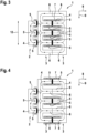
- Fig. 1 shows a view of an integrated magnetic component 1 according to a first embodiment of the present invention.
- the integrated magnetic component 1 of the present embodiment comprises one first type magnetic core element 2 and two second type magnetic core elements 3. Further, the integrated magnetic component 1 comprises electrical winding 7.
- the electrical winding 7 is shown in an illustrative, cross-sectional manner.
- the first type magnetic core element 2 comprises a yoke 4 and three legs 5.
- a first total number of legs 5 is defined as a number of said legs 5 of said first type magnetic core element 2.
- the second type magnetic core elements 3 respectively comprises a yoke 4 and five legs 5, 6.
- a second total number of legs 5, 6 is defined as a number of said legs 5, 6 of each of said second type magnetic core elements 3.
- the yoke 4 connects the legs 5, 6 of each magnetic core element 2, 3, wherein the legs 5, 6 extend from a side of the yoke 4.
- one first type magnetic core element 2 and two second type magnetic core elements 3 are stacked one on another along a stacking direction 8 such that their legs 5, 6 are arranged in row.
- the second of the two second type magnetic core elements 3 opposes the first of the two second type magnetic core elements 3.
- the present embodiment may also be referred so as a EWW or EWM configuration, with the "M” meaning "opposing W”.
- the first total number of legs 5 and the second total number of legs 5, 6 are each an addition of a respective number of winding legs 5, around which electric winding 7 is wound, with a number of return legs 6, around which no electric winding 7 is wound.
- the return legs 6, around which no winding 7 is wound, together with the yoke 4 close a magnetic circuit generated by a magnetic flux 10 by the windings 7 of the winding legs 5.
- the first total number of legs 5 is three and the second total number of legs 5, 6 is five.
- the first total number of legs 5 and the second total number of legs 5, 6 are non-equal.
- the number of winding legs 5 of the first type magnetic core element 2 and the number of winding legs 5 of the second type magnetic core element 3 are equal, specifically three.
- the number of return legs 6 of the first type magnetic core element 2 and the number of return legs 6 of the second type magnetic core element 3 are non-equal.
- the first type magnetic core element 2 (E-core) has no return legs 6
- the second type magnetic core element 3 (W-core) has two return legs 6.
- the winding legs 5 of the second type magnetic core elements 3 are the two outermost legs 5 and the middle leg 5 of the second type magnetic core elements 3.
- the winding legs 5 and the return legs 6 are arranged alternatingly along the yoke extension direction 9 (i.e. winding, return, winding, return, winding in yoke extension direction).
- air gaps 11 are provided between all winding legs 5 of the magnetic core elements 2, 3 and an adjacent yoke 4 or adjacent winding leg 5 of another magnetic core element 2, 3.
- the return legs 6 are not separated by air gaps 11.
- the electrical windings 7 of the two second type magnetic core elements 3 span or surround the respective air gaps 11.
- the electrical windings 7 of adjacent and opposing winding legs 5 of the two second type magnetic core elements 3 are separate electrical windings 7, i.e. not electrically directly connected to one another, in other words are insulated from one another, so as to constitute primary and secondary side of a transformer.
- the windings 7 may be in a bifilar arrangement or may be for example provided layer-for-layer in the stacking direction 8 (i.e. alternating layers).
- all winding legs 5 of the first type magnetic core element 2 and all winding legs 5 of the second type magnetic core elements 3 are arranged collinearly along and parallel to the stacking direction 8.
- This exemplary configuration has the particular advantage in that cooling of the integrated magnetic component 1 can be carried out easily on the outermost legs 5 of the second type magnetic core elements 3, i.e. on outer surfaces thereof, while providing three legs 5 for the first type magnetic core element 2 reduces weight, volume and costs of the integrated magnetic component 1. Furthermore, as opposed to a EE ⁇ configuration, the magnetic flux 10 is compensated in the return legs 6 of the two second type magnetic core elements 3 such that current imbalances, which can occur in three-phase 120° shifted current applications, can be balanced or compensated for.
- the shown exemplary configuration is especially suited for unidirectional LLC resonant converters, as will be shown below.
- Fig. 2 shows a view of an integrated magnetic component 1 according to a second embodiment of the present invention.
- the return legs 6 of the second type magnetic core elements 3 are respectively the two outermost legs 6 (i.e. top and bottom).
- the winding legs 5 are the middle three legs 5 of the second type magnetic core elements 3 such that these are arranged, along the yoke extension direction from top to bottom in return leg 6, winding leg 5, winding leg 5, winding leg 5, return leg 6.
- This embodiment additionally to the foregoing, has the particular advantage in that electromagnetic fields are screened by the outer return legs 6 and prevented from extending far outside of the integrated magnetic component 1, which reduces unwanted EMI (electromagnetic interference).
- two of the winding legs 5 of the first type magnetic core element 2 and two of the winding legs 5 of the second type magnetic core elements 3 are arranged non-collinearly along and parallel to the stacking direction 8.
- the respective middle legs 5, which are winding legs 5, are arranged collinearly along and parallel to the stacking direction 8.
- the outermost winding legs 5 of the first magnetic core element 2 are arranged collinearly with the outermost return legs 6 of the second magnetic core elements 3.
- Fig. 3 shows a view of an integrated magnetic component 1 according to a third embodiment of the present invention.
- Fig. 4 shows a view of an integrated magnetic component 1 according to a fourth embodiment of the present invention.
- a height 12 of the first type magnetic core element 2 along the yoke extension direction 9 is smaller than that of the two second type magnetic core elements 3.
- the winding legs 5 of the second type magnetic core elements 3 are the middle three legs 5, with the return legs 6 being the two outermost legs 6. Due to the height 12 of the first type magnetic core element 2, the winding legs 5 of the first type magnetic core element 2 are collinear with the winding legs 5 of the second type magnetic core elements 3. Thereby, particularly high suppression of EMI as well as size, weight and volume reduction can be achieved.
- the winding legs 5 of the second type magnetic core elements 3 are the two outermost legs 5 and the middle leg 5, with the return legs 6 therebetween in yoke extension direction 9.
- the winding legs 5 of the first type magnetic core element 2 are collinear with two return legs 6 and one (the middle) winding leg 5 of the second type magnetic core element 3.
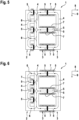
- Fig. 5 shows a view of an integrated magnetic component 1 according to a fifth embodiment of the present invention.
- Fig. 6 shows a view of an integrated magnetic component 1 according to a sixth embodiment of the present invention.
- the first type magnetic core element 2 comprises five legs 5, 6, and the second type magnetic core elements 3 respectively comprise three legs 5.
- the second type magnetic core elements 3 comprise no return legs 6, only winding legs 5.
- the winding legs 5 of the first type magnetic core element 2 are the two outermost legs 5 and the middle leg 5, especially with the winding legs 5 and the return legs 6 being arranged alternatingly along the yoke extension direction 9.
- This configuration has the particular advantage in that cooling can be carried out easily and efficiently on outer surfaces of the first type magnetic core element 2, while size, weight and costs are advantageously reduced by providing two E-core second type magnetic core elements 3.
- the return legs 6 of the first type magnetic core element 2 are the two outermost legs 6.
- the winding legs 5 of the first type magnetic core element 2 are the three middle legs 5 thereof.
- all winding legs 5 are collinear.
- two winding legs 5 of the first type magnetic core element 2 are non-collinear with two winding legs 5 of the second type magnetic core element 3.
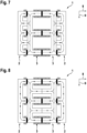
- Fig. 7 shows a view of an integrated magnetic component 1 according to a seventh embodiment of the present invention.
- Fig. 8 shows a view of an integrated magnetic component 1 according to an eighth embodiment of the present invention.
- the integrated magnetic component 1 further comprises another first type magnetic core element 2.
- Embodiment seven corresponds to embodiment five shown in Fig. 5 with an additional first type magnetic core element 2.
- Embodiment eight shown in Fig. 8 , corresponds to embodiment one shown in Fig. 1 with an additional first type magnetic core element 2. It is to be understood that any of the foregoing embodiments may be combined with an additional first type magnetic core element 2 as demonstrated by Figs. 7 and 8 .
- WE ⁇ W or WE ⁇ M
- LLC resonant converters of the present invention employing the foregoing described integrated magnetic components 1 are explained.
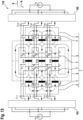
- circuitry of these LLC resonant converters are shown, along with inductances L rxx (result of electrical windings 7 and magnetic core elements 2,3), capacitors C rxx (subscript “r” standing for “resonance” or “resonant"), primary winding 7 (P xx ) and secondary winding 7 (S xx ) and air gaps 11 (g xxx ).
- Fig. 9 shows a view of a unidirectional LLC resonant converter 100 according to a ninth embodiment of the present invention.
- Fig. 10 shows a view of a unidirectional LLC resonant converter 100 according to a tenth embodiment of the present invention.
- Fig. 11 shows a view of a unidirectional LLC resonant converter 100 according to an eleventh embodiment of the present invention.
- the unidirectional LLC resonant converter 100 of embodiments nine to eleven comprises an input converter 101, an output converter 102, and the integrated magnetic component comprising 1 one first type magnetic core element 2 and two second type magnetic core elements 3.
- the input converter 101 is connected to the windings 7 of the one first type magnetic core element 2.
- the output converter 102 is connected to the windings 7 of the second, along the stacking direction 8, second type magnetic core element 3.
- the electrical windings 7 of the first type magnetic core element 2 are connected in series with the electrical windings 7 of the first second type magnetic core element 3.
- the first type magnetic core element 2, with its windings 7, is part of a choke.
- the two second type magnetic core elements 3 are part of primary and secondary sides of a transformer.
- the first of the second type magnetic core elements 3 is part of a primary side
- the second of the second type magnetic core elements 3 is part of a secondary side of a transformer.
- the first of the second type magnetic core elements 3 is also part of a secondary side
- the second of the second type magnetic core elements 3 is also part of a primary side of a transformer.
- the primary side and the secondary side of the transformer are electrically insulated from one another.
- an integrated magnetic component 1 of embodiment one is implemented.
- an integrated magnetic component 1 of embodiment five is implemented.
- an integrated magnetic component 1 of embodiment three is implemented.
- the foregoing implementation examples of the unidirectional LLC resonant converter 100 are illustrative.
- the unidirectional LLC resonant converter 100 can employ any one of the embodiments of the integrated magnetic component 1, especially embodiments one to six.
- Fig. 12 shows a view of a bidirectional LLC resonant converter 110 according to a twelfth embodiment of the present invention.
- Fig. 13 shows a view of a bidirectional LLC resonant converter 110 according to a thirteenth embodiment of the present invention.
- Fig. 14 shows a view of a bidirectional LLC resonant converter 110 according to a fourteenth embodiment of the present invention.
- the bidirectional LLC resonant converter 110 of embodiments twelve to fourteen comprises an input converter 101, an output converter 102, and the integrated magnetic component 1 comprising the two first type magnetic core elements 2 and the two second type magnetic core elements 3.
- the input converter 101 is connected to the windings 7 of the first, along the stacking direction 8, of the first type magnetic core elements 2
- the output converter 102 is connected to the windings 7 of the second, along the stacking direction 8, of the first type magnetic core elements 2.
- both the first type magnetic core elements 2, together with their windings 7, are part of chokes, whereas the second type magnetic core elements 3 are part of the transformer (primary and secondary side thereof) of the converter 110.
- an integrated magnetic component 1 of embodiment one with an additional first type magnetic core element 2 is implemented.
- an integrated magnetic component 1 of embodiment three with an additional first type magnetic core element 2 is implemented.
- an integrated magnetic component 1 of embodiment seven is implemented.
- the bidirectional LLC resonant converter 110 can employ any one of the embodiments of the integrated magnetic component 1, especially embodiments seven and eight, especially with an additional first type magnetic core element 2 in the case of embodiments one to six.
- an LLC resonant converter 100, 110 (unidirectional or bidirectional) is provided with the foregoing described advantages of reduced weight, volume and costs and in particular high maximum power delivery and efficiency with easy and efficient cooling and reduced EMI.
Landscapes
- Engineering & Computer Science (AREA)
- Power Engineering (AREA)
- Chemical & Material Sciences (AREA)
- Composite Materials (AREA)
- Dc-Dc Converters (AREA)
- Coils Or Transformers For Communication (AREA)
Priority Applications (3)
| Application Number | Priority Date | Filing Date | Title |
|---|---|---|---|
| EP23207784.2A EP4550366A1 (de) | 2023-11-03 | 2023-11-03 | Integrierte magnetische komponente und llc-resonanzwandler |
| CN202411497965.6A CN119943537A (zh) | 2023-11-03 | 2024-10-25 | 集成磁部件和llc谐振转换器 |
| US18/929,646 US20250149229A1 (en) | 2023-11-03 | 2024-10-29 | Integrated magnetic component and llc resonant converters |
Applications Claiming Priority (1)
| Application Number | Priority Date | Filing Date | Title |
|---|---|---|---|
| EP23207784.2A EP4550366A1 (de) | 2023-11-03 | 2023-11-03 | Integrierte magnetische komponente und llc-resonanzwandler |
Publications (1)
| Publication Number | Publication Date |
|---|---|
| EP4550366A1 true EP4550366A1 (de) | 2025-05-07 |
Family
ID=88697784
Family Applications (1)
| Application Number | Title | Priority Date | Filing Date |
|---|---|---|---|
| EP23207784.2A Pending EP4550366A1 (de) | 2023-11-03 | 2023-11-03 | Integrierte magnetische komponente und llc-resonanzwandler |
Country Status (3)
| Country | Link |
|---|---|
| US (1) | US20250149229A1 (de) |
| EP (1) | EP4550366A1 (de) |
| CN (1) | CN119943537A (de) |
Citations (4)
| Publication number | Priority date | Publication date | Assignee | Title |
|---|---|---|---|---|
| EP2689433B1 (de) * | 2011-03-23 | 2015-07-01 | Akademia Gorniczo-Hutnicza im. Stanislawa Staszica w Krakowie | Integrierter induktor und verfahren zur verringerung der verluste bei einem integrierten induktor |
| EP3401935A1 (de) | 2017-05-08 | 2018-11-14 | Delta Electronics (Thailand) Public Co., Ltd. | Integriertes magnetisches bauteil und leistungswandler |
| US20220399823A1 (en) * | 2021-06-14 | 2022-12-15 | Apple Inc. | Flyback Converters with Improved Magnetic Configurations |
| CN218182007U (zh) | 2022-09-28 | 2022-12-30 | 杭州士兰微电子股份有限公司 | 变压器结构 |
-
2023
- 2023-11-03 EP EP23207784.2A patent/EP4550366A1/de active Pending
-
2024
- 2024-10-25 CN CN202411497965.6A patent/CN119943537A/zh active Pending
- 2024-10-29 US US18/929,646 patent/US20250149229A1/en active Pending
Patent Citations (4)
| Publication number | Priority date | Publication date | Assignee | Title |
|---|---|---|---|---|
| EP2689433B1 (de) * | 2011-03-23 | 2015-07-01 | Akademia Gorniczo-Hutnicza im. Stanislawa Staszica w Krakowie | Integrierter induktor und verfahren zur verringerung der verluste bei einem integrierten induktor |
| EP3401935A1 (de) | 2017-05-08 | 2018-11-14 | Delta Electronics (Thailand) Public Co., Ltd. | Integriertes magnetisches bauteil und leistungswandler |
| US20220399823A1 (en) * | 2021-06-14 | 2022-12-15 | Apple Inc. | Flyback Converters with Improved Magnetic Configurations |
| CN218182007U (zh) | 2022-09-28 | 2022-12-30 | 杭州士兰微电子股份有限公司 | 变压器结构 |
Also Published As
| Publication number | Publication date |
|---|---|
| US20250149229A1 (en) | 2025-05-08 |
| CN119943537A (zh) | 2025-05-06 |
Similar Documents
| Publication | Publication Date | Title |
|---|---|---|
| US10971290B2 (en) | Magnetic assembly and power supply system with same | |
| US10389258B2 (en) | Integrated magnetic component and power converter | |
| US11349400B2 (en) | Multiple parallel-connected resonant converter, inductor-integrated magnetic element and transformer-integrated magnetic element | |
| US8031042B2 (en) | Power converter magnetic devices | |
| US7633369B2 (en) | Extended E matrix integrated magnetics (MIM) core | |
| CN113012894B (zh) | 集成变压器及电源变换器 | |
| CN101578672B (zh) | 兼有电抗器式变压器 | |
| CN211670766U (zh) | 磁性元件及其适用的开关电源装置 | |
| JP2014535172A (ja) | 誘導部品及び使用方法 | |
| EP2647117B1 (de) | Resonanzstromversorgung mit einem integrierten induktor | |
| CN111937286A (zh) | Llc谐振转换器 | |
| WO2019073650A1 (ja) | 変圧器および電力変換装置 | |
| US6100781A (en) | High leakage inductance transformer | |
| US20240177926A1 (en) | Transformer assembly and electric conversion device | |
| EP4550366A1 (de) | Integrierte magnetische komponente und llc-resonanzwandler | |
| EP4273894A1 (de) | Umrichterkomponente und umrichter | |
| US10186370B1 (en) | Transformers with integrated inductors | |
| CN110610795A (zh) | 一种用于二相整流器的三相变压器 | |
| CN116031051A (zh) | 变压器 | |
| US20250226144A1 (en) | Matrix transformer | |
| EP4303897A1 (de) | Magnetischer kern | |
| US20230260689A1 (en) | Transformer and dc-dc converter for on-board charger using the same | |
| US20250046506A1 (en) | Multi-phase transformer and llc resonant converter | |
| EP4503072A1 (de) | Planare transformatoren und llc-wandler | |
| JP2026512493A (ja) | 変圧器、及び変圧器を備える電気装置 |
Legal Events
| Date | Code | Title | Description |
|---|---|---|---|
| PUAI | Public reference made under article 153(3) epc to a published international application that has entered the european phase |
Free format text: ORIGINAL CODE: 0009012 |
|
| STAA | Information on the status of an ep patent application or granted ep patent |
Free format text: STATUS: THE APPLICATION HAS BEEN PUBLISHED |
|
| AK | Designated contracting states |
Kind code of ref document: A1 Designated state(s): AL AT BE BG CH CY CZ DE DK EE ES FI FR GB GR HR HU IE IS IT LI LT LU LV MC ME MK MT NL NO PL PT RO RS SE SI SK SM TR |
|
| STAA | Information on the status of an ep patent application or granted ep patent |
Free format text: STATUS: REQUEST FOR EXAMINATION WAS MADE |
|
| 17P | Request for examination filed |
Effective date: 20251024 |